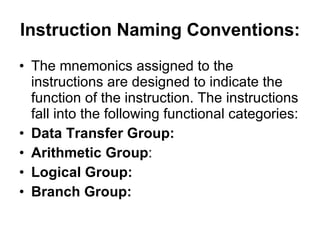
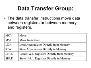
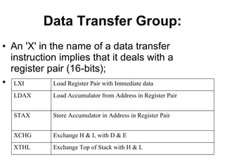
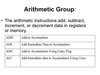
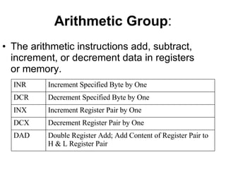
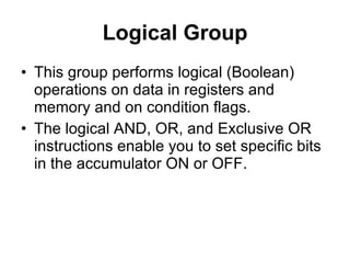
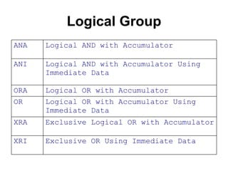
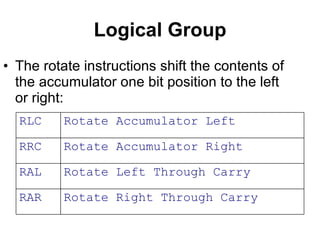
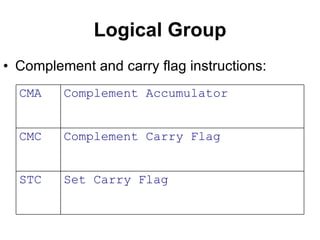
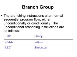
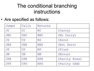
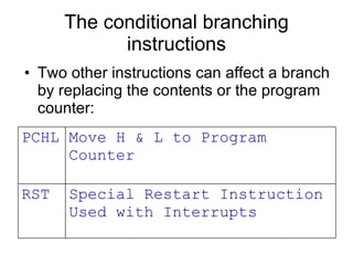
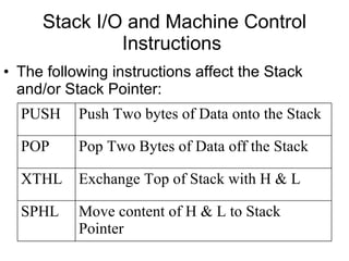
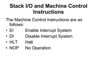
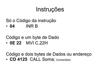
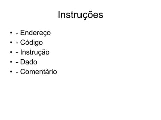
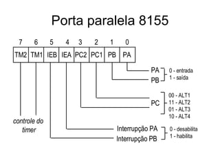
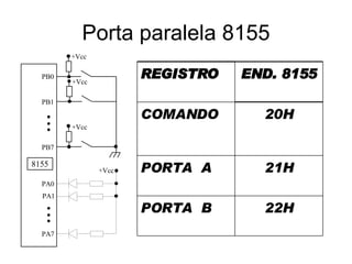
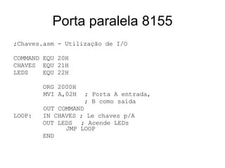
8085 Instruções
Instruction Naming Conventions:   The mnemonics assigned to the instructions are designed to indicate the function of the instruction. The instructions fall into the following functional categories:  Data Transfer Group:   Arithmetic Group : Logical Group:   Branch Group:
Data Transfer Group: The data transfer instructions move data between registers or between memory and registers. Store H & L Registers Directly in Memory SHLD Load H & L Registers Directly from Memory LHLD Store Accumulator Directly in Memory STA Load Accumulator Directly from Memory LDA Move Immediate MVI Move MOV
Data Transfer Group: An 'X' in the name of a data transfer instruction implies that it deals with a register pair (16-bits);   Exchange Top of Stack with H & L XTHL Exchange H & L with D & E XCHG Store Accumulator in Address in Register Pair STAX Load Accumulator from Address in Register Pair LDAX Load Register Pair with Immediate data LXI
Arithmetic Group : The arithmetic instructions add, subtract, increment, or decrement data in registers or memory.   Add Immediate data to Accumulator Using Carry  ACI Add to Accumulator Using Carry Flag ADC Add Immediate Data to Accumulator ADI Add to Accumulator ADD
Arithmetic Group : The arithmetic instructions add, subtract, increment, or decrement data in registers or memory.   Subtract Immediate from Accumulator Using Borrow (Carry) Flag SBI Subtract from Accumulator Using Borrow (Carry) Flag SBB Subtract Immediate Data from Accumulator SUI Subtract from Accumulator SUB
Arithmetic Group : The arithmetic instructions add, subtract, increment, or decrement data in registers or memory.   Double Register Add; Add Content of Register Pair to H & L Register Pair DAD Decrement Register Pair by One DCX Increment Register Pair by One INX Decrement Specified Byte by One DCR Increment Specified Byte by One INR
Logical Group This group performs logical (Boolean) operations on data in registers and memory and on condition flags. The logical AND, OR, and Exclusive OR instructions enable you to set specific bits in the accumulator ON or OFF.
Logical Group Exclusive OR Using Immediate Data XRI Exclusive Logical OR with Accumulator XRA Logical OR with Accumulator Using Immediate Data OR Logical OR with Accumulator ORA Logical AND with Accumulator Using Immediate Data ANI Logical AND with Accumulator ANA
Logical Group The Compare instructions compare the content of an 8-bit value with the contents of the accumulator; Compare Using Immediate Data CPI Compare CMP
Logical Group The rotate instructions shift the contents of the accumulator one bit position to the left or right:   Rotate Right Through Carry RAR Rotate Left Through Carry RAL Rotate Accumulator Right RRC Rotate Accumulator Left RLC
Logical Group Complement and carry flag instructions: Set Carry Flag STC Complement Carry Flag CMC Complement Accumulator CMA
Branch Group   The branching instructions alter normal sequential program flow, either unconditionally or conditionally. The unconditional branching instructions are as follows: Return RET Call CALL Jump JMP
Conditional branching instructions examine the status of one of four condition flags to determine whether the specified branch is to be executed.  Minus (S = 1) M Plus (S = 0) P Parity Even (P        = 1) PE Parity Odd (P = 0) PO Carry (C = 1) C No Carry (C = 0) NC Zero (Z = 1) Z Not Zero (Z = 0) NZ
The conditional branching instructions Are specified as follows: (Parity Odd) RPO CPO JP0 (Parity Even) RPE CPE JPE (Minus) RM CM JM (Plus) RP CP JP (Not Zero) RNZ CNZ JNZ (Zero) RZ CZ JZ (No Carry) RNC CNC JNC (Carry) RC CC JC Returns Calls Jumps
The conditional branching instructions Two other instructions can affect a branch by replacing the contents or the program counter:   Special Restart Instruction Used with Interrupts RST Move H & L to Program Counter PCHL
Stack I/O and Machine Control Instructions   The following instructions affect the Stack and/or Stack Pointer: Move content of H & L to Stack Pointer SPHL Exchange Top of Stack with H & L XTHL Pop Two Bytes of Data off the Stack POP Push Two bytes of Data onto the Stack PUSH
Stack I/O and Machine Control Instructions The I/0 instructions are as follows IN Initiate Input Operation OUT Initiate Output Operation
Stack I/O and Machine Control Instructions The Machine Control instructions are as follows: EI Enable Interrupt System DI Disable Interrupt System HLT Halt NOP No Operation
Instruções Só o Código da instrução 04 INR B Código e um byte de Dado 0E 22 MVI C,22H Código e dois bytes de Dados ou endereço CD 4125   CALL Soma;  Comentário
Instruções - Endereço  - Código - Instrução - Dado - Comentário
Instruções INR A  MVI A,25H 2000 3C INR A ; Atualiza cont 2001 3E  25 MVI A,25; ???? 2003 CD 25 41 CALL Soma
Sub routinas
Rotinas do Monitor KIT 8085 Monitor Eprom 0000H- 1FFFH  RAM 2000H – 2400H Programa
Rotinas do Monitor Atraso A D E 05F1 Delay MostraDE todos  0363 MostraD MostraA todos  036E MostraA Ler p/A A H L 02E7 Letecla função altera endereço Nome
LOOP xxxx ; atraso : DCR D JNZ LOOP
Sistema de Desenvolvimento Editor  Montador  Compilador Simulador Gravador Emulador
Sistema de Desenvolvimento Crossware  – Edita e Compila Abacus  – Simulador PINNACLE  – para 8051
EXEMPLO CONT1.ASM ; EXEMPLO CONT1.ASM ; Este programa realiza uma contagem decimal a partir de 7 MOSTRAA equ 036EH MOSTRAD equ 0363H DELAY equ 05f1H ORG 2000h LXI SP,20C2H LOOP: ADI 1 ; INCREMENTAR  DAA   ; AJUSTE PARA DECIMAL STA  MEMORIA ; SALVAR Valor MOV E,A MVI D,0 CALL  MOSTRAD ; Mostrar em DE LDA MEMORIA ; RECUPERAR  JMP LOOP MEMORIA  DB 7 END
Problemas no desenvolvimento de programas!! Erros de Sintaxe Não colocar END Não definir a pilha Definir a pilha em local inadequado Definir endereços errados  Erros de lógica !!!!!!!!!!!!!!!!!
Diretivas ORG   2000H  - Origem END Dado   DB  25H ; define dado=25 Dado   DW   25H ; define dado=0025 MSG   DB   ‘ Microprocessador’ DELAY EQU   05F1h LETECLA EQU   02E7h CHAVES EQU  21h LEDS   EQU  22h
Quando  Utilizar  Assembly ? Quando for necessário extrair o máximo desempenho dos procedimentos críticos de um programa em linguagem de alto nível. Em microprocessadores voltados para sistemas pequenos (dedicados), o Assembly pode ser a única alternativa .
Quando  Utilizar  Assembly ? Geralmente os compiladores de linguagens de alto nível também executam o processo de montagem.   Portanto, entender de Assembly é essencial para entender o funcionamento dos compiladores .
O  Processo  de  Montagem É bastante semelhante entre máquinas diferentes. O código assembly contém muitas referências futuras. Os montadores podem ser de dois passos ou de um passo. Montador de dois passos : Lê o programa-fonte duas vezes.    No passo 1:  Elimina todas as referências futuras; Coleciona as definições de todos os símbolos em uma tabela.
O  Processo  de  Montagem    No passo 2: Cada comando pode ser lido, montado e dar saída. Montador de um passo:  Lê o programa-fonte somente uma vez para fazer a montagem. Os comandos com referências futuras são guardados em uma tabela para serem montados após o término da leitura do programa. A maioria dos montadores é de dois passos.
Porta paralela 8155
Porta paralela 8155 22H PORTA  B 21H PORTA  A 20H COMANDO END. 8155 REGISTRO
Porta paralela 8155 ;Chaves.asm - Utilização de I/O COMMAND EQU 20H  CHAVES  EQU 21H LEDS  EQU 22H ORG 2000H   MVI A,02H  ; Porta A entrada,    ; B como saída   OUT COMMAND LOOP:  IN CHAVES ; Le chaves p/A OUT LEDS ; Acende LEDs    JMP LOOP END
Porta paralela 8155 Deslocar um led  para a Esquerda. A int TRAP alterna entre led ligado ou apagado
Porta paralela 8155 COMMAND EQU 20H CHAVES EQU 21H LEDS EQU 22H MVI A,02H  ; B é saída OUT COMMAND SIM EI LOOP: LDA DADO OUT LEDS ; Acende o LEDs RLC  ; Rotaciona LED STA DADO MVI D,02H  ; Atraso de 200ms CALL DELAY  ; p/ ver LED  JMP LOOP
Porta paralela 8155 TTRAP: PUSH PSW LDA DADO CMA STA DADO EI POP PSW RET DADO DB 01 ; valor inicial ORG TRAP JMP TTRAP END RST  ; xx – Alterna  SENTIDO !!
Manipulação de bits Operações booleanas !! Manipulação com mascaras Registro 11111x00 Mascara 0000 111 0 Operação  OR 1111 111 0 SETAR o BIT  definido com 1 na mascara
Manipulação de bits RESETAR  UM ou mais bits Registro 11111100 Mascara 0000 1111 Operação  AND 0000 1100 Reseta o BIT cuja mascara for zero !!!!
Manipulação de bits COMPLEMENTAR  UM ou mais bits Registro 11111100 Mascara 0000 1111 Operação  XOR 0000 0011 Complementa os bits cuja mascara for um
; Testar o Bit0 de  DADO ; Se tiver em 1 Resetar o  BIT7 ; e caso contrário Setar o BIT6 INICIO:  LDA DADO ANI 01 JZ SETA6   LDA DADO ANI 7FH  ; resetar bit7 STA DADO JMP INICIO SETA6:  LDA DADO    ORI 01000000B; set B6 STA DADO JMP INICIO DADO   DB 0FFH END
Exercício1 Deslocar um LED ligado para a esquerda no conjunto de Leds.
Exercício2 Deslocar um LED ligado para a esquerda no conjunto de Leds. As chaves 7 e 8 definem a velocidade de deslocamento.
Exercício3 Deslocar um LED ligado para a esquerda no conjunto de Leds. A chave 1 define o sentido. Ligada – para a direita e desligada para a esquerda.
Exercício4 Deslocar um LED ligado para a esquerda no conjunto de Leds. A chave 2 controla entre deslocar um LED aceso e um desligado ! As chaves 3, 4 e 5 ....
Exercício5 Deslocar um LED ligado para a esquerda no conjunto de Leds. As chaves 3, 4 e 5 .... Coloque algumas funções para as chaves 3,4,5 utilizando os exemplos dos exercícios anteriores

8085 2

  • 1.
  • 2.
    Instruction Naming Conventions: The mnemonics assigned to the instructions are designed to indicate the function of the instruction. The instructions fall into the following functional categories: Data Transfer Group: Arithmetic Group : Logical Group: Branch Group:
  • 3.
    Data Transfer Group:The data transfer instructions move data between registers or between memory and registers. Store H & L Registers Directly in Memory SHLD Load H & L Registers Directly from Memory LHLD Store Accumulator Directly in Memory STA Load Accumulator Directly from Memory LDA Move Immediate MVI Move MOV
  • 4.
    Data Transfer Group:An 'X' in the name of a data transfer instruction implies that it deals with a register pair (16-bits);   Exchange Top of Stack with H & L XTHL Exchange H & L with D & E XCHG Store Accumulator in Address in Register Pair STAX Load Accumulator from Address in Register Pair LDAX Load Register Pair with Immediate data LXI
  • 5.
    Arithmetic Group :The arithmetic instructions add, subtract, increment, or decrement data in registers or memory.   Add Immediate data to Accumulator Using Carry ACI Add to Accumulator Using Carry Flag ADC Add Immediate Data to Accumulator ADI Add to Accumulator ADD
  • 6.
    Arithmetic Group :The arithmetic instructions add, subtract, increment, or decrement data in registers or memory.   Subtract Immediate from Accumulator Using Borrow (Carry) Flag SBI Subtract from Accumulator Using Borrow (Carry) Flag SBB Subtract Immediate Data from Accumulator SUI Subtract from Accumulator SUB
  • 7.
    Arithmetic Group :The arithmetic instructions add, subtract, increment, or decrement data in registers or memory.   Double Register Add; Add Content of Register Pair to H & L Register Pair DAD Decrement Register Pair by One DCX Increment Register Pair by One INX Decrement Specified Byte by One DCR Increment Specified Byte by One INR
  • 8.
    Logical Group Thisgroup performs logical (Boolean) operations on data in registers and memory and on condition flags. The logical AND, OR, and Exclusive OR instructions enable you to set specific bits in the accumulator ON or OFF.
  • 9.
    Logical Group ExclusiveOR Using Immediate Data XRI Exclusive Logical OR with Accumulator XRA Logical OR with Accumulator Using Immediate Data OR Logical OR with Accumulator ORA Logical AND with Accumulator Using Immediate Data ANI Logical AND with Accumulator ANA
  • 10.
    Logical Group TheCompare instructions compare the content of an 8-bit value with the contents of the accumulator; Compare Using Immediate Data CPI Compare CMP
  • 11.
    Logical Group Therotate instructions shift the contents of the accumulator one bit position to the left or right: Rotate Right Through Carry RAR Rotate Left Through Carry RAL Rotate Accumulator Right RRC Rotate Accumulator Left RLC
  • 12.
    Logical Group Complementand carry flag instructions: Set Carry Flag STC Complement Carry Flag CMC Complement Accumulator CMA
  • 13.
    Branch Group The branching instructions alter normal sequential program flow, either unconditionally or conditionally. The unconditional branching instructions are as follows: Return RET Call CALL Jump JMP
  • 14.
    Conditional branching instructionsexamine the status of one of four condition flags to determine whether the specified branch is to be executed. Minus (S = 1) M Plus (S = 0) P Parity Even (P        = 1) PE Parity Odd (P = 0) PO Carry (C = 1) C No Carry (C = 0) NC Zero (Z = 1) Z Not Zero (Z = 0) NZ
  • 15.
    The conditional branchinginstructions Are specified as follows: (Parity Odd) RPO CPO JP0 (Parity Even) RPE CPE JPE (Minus) RM CM JM (Plus) RP CP JP (Not Zero) RNZ CNZ JNZ (Zero) RZ CZ JZ (No Carry) RNC CNC JNC (Carry) RC CC JC Returns Calls Jumps
  • 16.
    The conditional branchinginstructions Two other instructions can affect a branch by replacing the contents or the program counter: Special Restart Instruction Used with Interrupts RST Move H & L to Program Counter PCHL
  • 17.
    Stack I/O andMachine Control Instructions The following instructions affect the Stack and/or Stack Pointer: Move content of H & L to Stack Pointer SPHL Exchange Top of Stack with H & L XTHL Pop Two Bytes of Data off the Stack POP Push Two bytes of Data onto the Stack PUSH
  • 18.
    Stack I/O andMachine Control Instructions The I/0 instructions are as follows IN Initiate Input Operation OUT Initiate Output Operation
  • 19.
    Stack I/O andMachine Control Instructions The Machine Control instructions are as follows: EI Enable Interrupt System DI Disable Interrupt System HLT Halt NOP No Operation
  • 20.
    Instruções Só oCódigo da instrução 04 INR B Código e um byte de Dado 0E 22 MVI C,22H Código e dois bytes de Dados ou endereço CD 4125 CALL Soma; Comentário
  • 21.
    Instruções - Endereço - Código - Instrução - Dado - Comentário
  • 22.
    Instruções INR A MVI A,25H 2000 3C INR A ; Atualiza cont 2001 3E 25 MVI A,25; ???? 2003 CD 25 41 CALL Soma
  • 23.
  • 24.
    Rotinas do MonitorKIT 8085 Monitor Eprom 0000H- 1FFFH RAM 2000H – 2400H Programa
  • 25.
    Rotinas do MonitorAtraso A D E 05F1 Delay MostraDE todos 0363 MostraD MostraA todos 036E MostraA Ler p/A A H L 02E7 Letecla função altera endereço Nome
  • 26.
    LOOP xxxx ;atraso : DCR D JNZ LOOP
  • 27.
    Sistema de DesenvolvimentoEditor Montador Compilador Simulador Gravador Emulador
  • 28.
    Sistema de DesenvolvimentoCrossware – Edita e Compila Abacus – Simulador PINNACLE – para 8051
  • 29.
    EXEMPLO CONT1.ASM ;EXEMPLO CONT1.ASM ; Este programa realiza uma contagem decimal a partir de 7 MOSTRAA equ 036EH MOSTRAD equ 0363H DELAY equ 05f1H ORG 2000h LXI SP,20C2H LOOP: ADI 1 ; INCREMENTAR DAA ; AJUSTE PARA DECIMAL STA MEMORIA ; SALVAR Valor MOV E,A MVI D,0 CALL MOSTRAD ; Mostrar em DE LDA MEMORIA ; RECUPERAR JMP LOOP MEMORIA DB 7 END
  • 30.
    Problemas no desenvolvimentode programas!! Erros de Sintaxe Não colocar END Não definir a pilha Definir a pilha em local inadequado Definir endereços errados Erros de lógica !!!!!!!!!!!!!!!!!
  • 31.
    Diretivas ORG 2000H - Origem END Dado DB 25H ; define dado=25 Dado DW 25H ; define dado=0025 MSG DB ‘ Microprocessador’ DELAY EQU 05F1h LETECLA EQU 02E7h CHAVES EQU 21h LEDS EQU 22h
  • 32.
    Quando Utilizar Assembly ? Quando for necessário extrair o máximo desempenho dos procedimentos críticos de um programa em linguagem de alto nível. Em microprocessadores voltados para sistemas pequenos (dedicados), o Assembly pode ser a única alternativa .
  • 33.
    Quando Utilizar Assembly ? Geralmente os compiladores de linguagens de alto nível também executam o processo de montagem. Portanto, entender de Assembly é essencial para entender o funcionamento dos compiladores .
  • 34.
    O Processo de Montagem É bastante semelhante entre máquinas diferentes. O código assembly contém muitas referências futuras. Os montadores podem ser de dois passos ou de um passo. Montador de dois passos : Lê o programa-fonte duas vezes.  No passo 1: Elimina todas as referências futuras; Coleciona as definições de todos os símbolos em uma tabela.
  • 35.
    O Processo de Montagem  No passo 2: Cada comando pode ser lido, montado e dar saída. Montador de um passo: Lê o programa-fonte somente uma vez para fazer a montagem. Os comandos com referências futuras são guardados em uma tabela para serem montados após o término da leitura do programa. A maioria dos montadores é de dois passos.
  • 36.
  • 37.
    Porta paralela 815522H PORTA B 21H PORTA A 20H COMANDO END. 8155 REGISTRO
  • 38.
    Porta paralela 8155;Chaves.asm - Utilização de I/O COMMAND EQU 20H CHAVES EQU 21H LEDS EQU 22H ORG 2000H MVI A,02H ; Porta A entrada, ; B como saída OUT COMMAND LOOP: IN CHAVES ; Le chaves p/A OUT LEDS ; Acende LEDs JMP LOOP END
  • 39.
    Porta paralela 8155Deslocar um led para a Esquerda. A int TRAP alterna entre led ligado ou apagado
  • 40.
    Porta paralela 8155COMMAND EQU 20H CHAVES EQU 21H LEDS EQU 22H MVI A,02H ; B é saída OUT COMMAND SIM EI LOOP: LDA DADO OUT LEDS ; Acende o LEDs RLC ; Rotaciona LED STA DADO MVI D,02H ; Atraso de 200ms CALL DELAY ; p/ ver LED JMP LOOP
  • 41.
    Porta paralela 8155TTRAP: PUSH PSW LDA DADO CMA STA DADO EI POP PSW RET DADO DB 01 ; valor inicial ORG TRAP JMP TTRAP END RST ; xx – Alterna SENTIDO !!
  • 42.
    Manipulação de bitsOperações booleanas !! Manipulação com mascaras Registro 11111x00 Mascara 0000 111 0 Operação OR 1111 111 0 SETAR o BIT definido com 1 na mascara
  • 43.
    Manipulação de bitsRESETAR UM ou mais bits Registro 11111100 Mascara 0000 1111 Operação AND 0000 1100 Reseta o BIT cuja mascara for zero !!!!
  • 44.
    Manipulação de bitsCOMPLEMENTAR UM ou mais bits Registro 11111100 Mascara 0000 1111 Operação XOR 0000 0011 Complementa os bits cuja mascara for um
  • 45.
    ; Testar oBit0 de DADO ; Se tiver em 1 Resetar o BIT7 ; e caso contrário Setar o BIT6 INICIO: LDA DADO ANI 01 JZ SETA6 LDA DADO ANI 7FH ; resetar bit7 STA DADO JMP INICIO SETA6: LDA DADO ORI 01000000B; set B6 STA DADO JMP INICIO DADO DB 0FFH END
  • 46.
    Exercício1 Deslocar umLED ligado para a esquerda no conjunto de Leds.
  • 47.
    Exercício2 Deslocar umLED ligado para a esquerda no conjunto de Leds. As chaves 7 e 8 definem a velocidade de deslocamento.
  • 48.
    Exercício3 Deslocar umLED ligado para a esquerda no conjunto de Leds. A chave 1 define o sentido. Ligada – para a direita e desligada para a esquerda.
  • 49.
    Exercício4 Deslocar umLED ligado para a esquerda no conjunto de Leds. A chave 2 controla entre deslocar um LED aceso e um desligado ! As chaves 3, 4 e 5 ....
  • 50.
    Exercício5 Deslocar umLED ligado para a esquerda no conjunto de Leds. As chaves 3, 4 e 5 .... Coloque algumas funções para as chaves 3,4,5 utilizando os exemplos dos exercícios anteriores