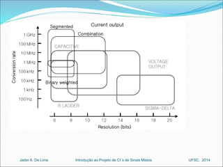
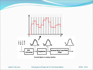
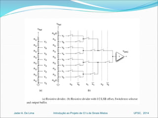
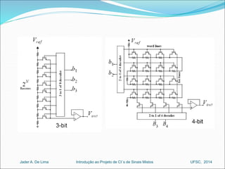
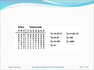
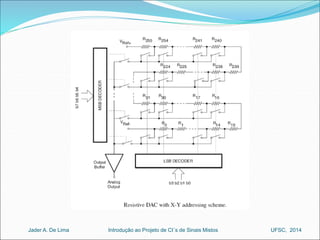
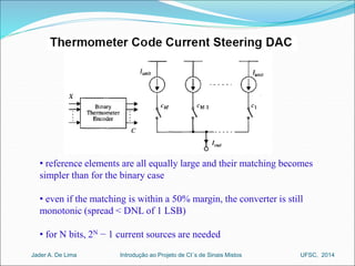
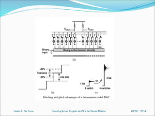
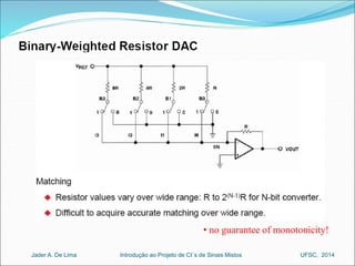
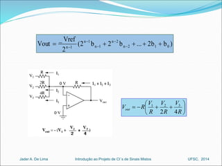
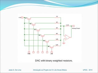
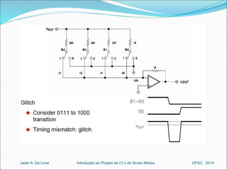
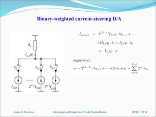
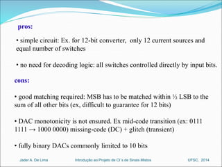
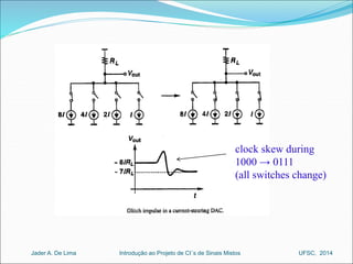
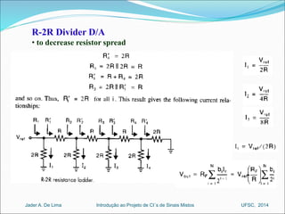
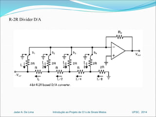
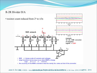
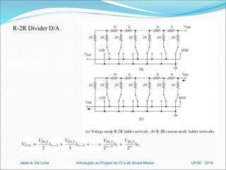
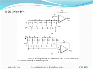
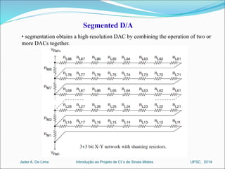
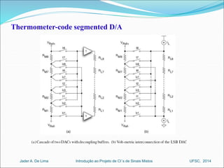
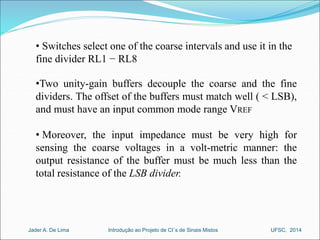
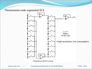
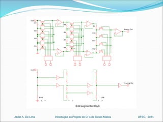
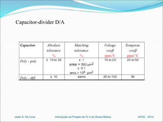
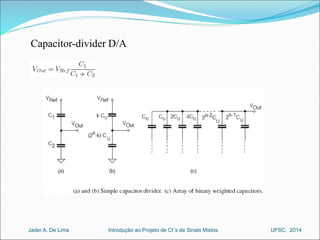
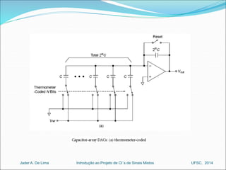
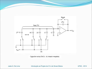
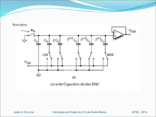
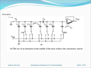
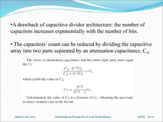
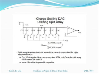
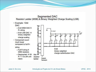
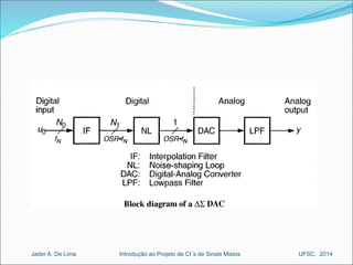
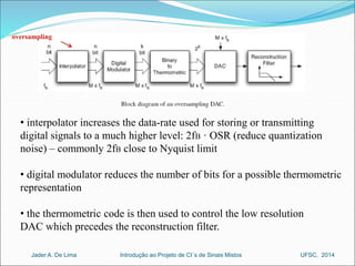
D/A Converters 
Prof. Jader A. De Lima 
Introdução ao Jader A. De Lima Projeto de CI´s de Sinais Mistos UFSC, 2014
D/A Converters 
Introdução ao Jader A. De Lima Projeto de CI´s de Sinais Mistos UFSC, 2014
Deglitching 
Introdução ao Jader A. De Lima Projeto de CI´s de Sinais Mistos UFSC, 2014
 monotonicity is guaranteed only in a thermometer-coded DAC 
Introdução ao Jader A. De Lima Projeto de CI´s de Sinais Mistos UFSC, 2014
offset error 
Introdução ao Jader A. De Lima Projeto de CI´s de Sinais Mistos UFSC, 2014
D/A Converter (Nyquist Rate) 
Introdução ao Jader A. De Lima Projeto de CI´s de Sinais Mistos UFSC, 2014
Thermometer Resistive-Divider D/A 
Introdução ao Jader A. De Lima Projeto de CI´s de Sinais Mistos UFSC, 2014
• reference elements are all equally large and their matching becomes 
simpler than for the binary case 
• even if the matching is within a 50% margin, the converter is still 
monotonic (spread < DNL of 1 LSB) 
• for N bits, 2N − 1 current sources are needed 
Introdução ao Jader A. De Lima Projeto de CI´s de Sinais Mistos UFSC, 2014
pros: 
• monotonic by construction: analog output always increases with 
digital input 
• no problem at mid-code transition (ex: 0111 1111 → 1000 0000) as 
only ONE current source is switched. Glitches are reduced. 
cons: 
• design complexity: 2N − 1 current sources. Large output capacitance 
(Ex: 12 bits, 4095 current sources and switches) 
• large area 
• matching problems 
• larger timing uncertainty of the switches. 
Introdução ao Jader A. De Lima Projeto de CI´s de Sinais Mistos UFSC, 2014
• no guarantee of monotonicity! 
Introdução ao Jader A. De Lima Projeto de CI´s de Sinais Mistos UFSC, 2014
 
 
 
n 2 
n 1 
 
 
Vout n 2 1 0 
n 1       
(2 b 2 b ... 2b b ) 
 
V 
V 
1 2 3 
V   R   
out 2 4 
 
 
V 
R 
R 
R 
_ Vref 
2 
n  
1 
 
Introdução ao Jader A. De Lima Projeto de CI´s de Sinais Mistos UFSC, 2014
Binary-weighted current-steering D/A 
digital word 
Introdução ao Jader A. De Lima Projeto de CI´s de Sinais Mistos UFSC, 2014
pros: 
• simple circuit: Ex. for 12-bit converter, only 12 current sources and 
equal number of switches 
• no need for decoding logic: all switches controlled directly by input bits. 
cons: 
• good matching required: MSB has to be matched within ½ LSB to the 
sum of all other bits (ex, difficult to guarantee for 12 bits) 
• DAC monotonicity is not ensured. Ex mid-code transition (ex: 0111 
1111 → 1000 0000) missing-code (DC) + glitch (transient) 
• fully binary DACs commonly limited to 10 bits 
Introdução ao Jader A. De Lima Projeto de CI´s de Sinais Mistos UFSC, 2014
clock skew during 
1000 → 0111 
(all switches change) 
Introdução ao Jader A. De Lima Projeto de CI´s de Sinais Mistos UFSC, 2014
R-2R Divider D/A 
• to decrease resistor spread 
Introdução ao Jader A. De Lima Projeto de CI´s de Sinais Mistos UFSC, 2014
R-2R Divider D/A 
Introdução ao Jader A. De Lima Projeto de CI´s de Sinais Mistos UFSC, 2014
R-2R Divider D/A 
• resistor count reduced from 2n to 3n 
Introdução ao Jader A. De Lima Projeto de CI´s de Sinais Mistos UFSC, 2014 
EEL 410026 – Introdução ao Projeto de CI´s de Sinais Mistos CMOS J. A. De Lima (EEL/UFSC)
R-2R Divider D/A 
Introdução ao Jader A. De Lima Projeto de CI´s de Sinais Mistos UFSC, 2014
R-2R Divider D/A 
Introdução ao Jader A. De Lima Projeto de CI´s de Sinais Mistos UFSC, 2014
• the layout of resistors consumes a relatively large area if the value of unity 
resistance is large and the used layer has a low specific resistance (like low-resistive 
poly) 
• for medium accuracy it is possible to save silicon area by replacing the resistors 
with MOS transistors 
• all transistors have identical (W/L) 
Introdução ao Jader A. De Lima Projeto de CI´s de Sinais Mistos UFSC, 2014
thermometer 
Introdução ao Jader A. De Lima Projeto de CI´s de Sinais Mistos UFSC, 2014
• segmentation: combination of binary and thermometer coding 
• thermometer code is used for MSBs, while binary code for LSBs 
• 0% segmentation = fully binary converter 
•100% segmentation = a full thermometer code converter 
• low segmentation  circuit simplicity (only a few current sources and 
switches), but larger DNL 
• large segmentation  lower DNL, but increased problems due to output 
conductance, capacitance and charge feedthrough, as well as larger area and 
power consumption. 
 optimum segmentation has to be found by the designer! 
Introdução ao Jader A. De Lima Projeto de CI´s de Sinais Mistos UFSC, 2014
Segmented D/A 
• segmentation obtains a high-resolution DAC by combining the operation of two or 
more DACs together. 
Introdução ao Jader A. De Lima Projeto de CI´s de Sinais Mistos UFSC, 2014
Thermometer-code segmented D/A 
Introdução ao Jader A. De Lima Projeto de CI´s de Sinais Mistos UFSC, 2014
• Switches select one of the coarse intervals and use it in the 
fine divider RL1 − RL8 
•Two unity-gain buffers decouple the coarse and the fine 
dividers. The offset of the buffers must match well ( < LSB), 
and must have an input common mode range VREF 
• Moreover, the input impedance must be very high for 
sensing the coarse voltages in a volt-metric manner: the 
output resistance of the buffer must be much less than the 
total resistance of the LSB divider. 
Introdução ao Jader A. De Lima Projeto de CI´s de Sinais Mistos UFSC, 2014
• high-resolution, low consumption 
Thermometer-code segmented D/A 
Introdução ao Jader A. De Lima Projeto de CI´s de Sinais Mistos UFSC, 2014
Capacitor-divider D/A 
Introdução ao Jader A. De Lima Projeto de CI´s de Sinais Mistos UFSC, 2014
Capacitor-divider D/A 
Introdução ao Jader A. De Lima Projeto de CI´s de Sinais Mistos UFSC, 2014
Reset phase 
Introdução ao Jader A. De Lima Projeto de CI´s de Sinais Mistos UFSC, 2014
Reset phase 
Introdução ao Jader A. De Lima Projeto de CI´s de Sinais Mistos UFSC, 2014
•A drawback of capacitive divider architecture: the number of 
capacitors increases exponentially with the number of bits. 
• The capacitors’ count can be reduced by dividing the capacitive 
array into two parts separated by an attenuation capacitance, CA. 
Introdução ao Jader A. De Lima Projeto de CI´s de Sinais Mistos UFSC, 2014
Oversampling (SD) DAC 
• basically, a S–D ADC in reverse! 
• principle of operation of oversampled DAC is very similar to 
oversampled ADC (resolution increases with sampling frequency) 
• improves SNR using noise shaping 
• processing is done in the digital domain to generate a digital string at 
one-bit DAC output. The average duty-cycle of the output string is 
proportional to the value of the binary input 
• the analog signal is created by passing the pulse string 
through an analog low-pass filter 
Introdução ao Jader A. De Lima Projeto de CI´s de Sinais Mistos UFSC, 2014
S–D DAC: fully digital 
Introdução ao Jader A. De Lima Projeto de CI´s de Sinais Mistos UFSC, 2014
oversampling 
• interpolator increases the data-rate used for storing or transmitting 
digital signals to a much higher level: 2fB · OSR (reduce quantization 
noise) – commonly 2fB close to Nyquist limit 
• digital modulator reduces the number of bits for a possible thermometric 
representation 
• the thermometric code is then used to control the low resolution 
DAC which precedes the reconstruction filter. 
Introdução ao Jader A. De Lima Projeto de CI´s de Sinais Mistos UFSC, 2014
Ex: 
Introdução ao Jader A. De Lima Projeto de CI´s de Sinais Mistos UFSC, 2014
• interpolation (upsampling) 
ex: interpolation by a factor L = 4 
Introdução ao Jader A. De Lima Projeto de CI´s de Sinais Mistos UFSC, 2014
• the interpolation factor (L) is normally large because a ΣΔ DAC aims 
at a significant reduction of the number of bit (at the limit it should go 
down to 1-bit) 
• oversampling is common in digital audio CD players, where the basic 
update rate of the data from the CD is 44.1 KSPS 
• early CD players used traditional binary DACs and inserted "zeros" 
into the parallel data, thereby increasing the effective update rate to 4- 
times, 8-times, or 16-times the fundamental throughput rate 
• the 4×, 8×, or 16× data stream is passed through a digital interpolation 
filter which generates the extra data points. 
Introdução ao Jader A. De Lima Projeto de CI´s de Sinais Mistos UFSC, 2014
• first step: to stuff (L-1) zero-valued samples between each valid 
input sample, expanding the sampling rate by L, and causing the 
original signal spectrum to be repeated L-1 times. 
• to perform the actual interpolation, the zero-valued 
input samples must be converted to approximations of signal 
samples  equivalent to preserving the original signal spectrum. 
• effectively, the zero-stuffed input stream is filtered by 
a low-pass filter with a pass band at the original spectrum location. 
 this filters out all of the repeated spectra. 
Introdução ao Jader A. De Lima Projeto de CI´s de Sinais Mistos UFSC, 2014
Latches Latches 
Divide By 
K 
Introdução ao Jader A. De Lima Projeto de CI´s de Sinais Mistos UFSC, 2014 
Clock 
+ 
MUX 
Shift 
Register 
Latches 
+ 
Clock/2 Latches 
Input bits 
Output bits 
Interpolation filter block diagram
Introdução ao Jader A. De Lima Projeto de CI´s de Sinais Mistos UFSC, 2014
http://www.ti.com/lit/an/slyt076/slyt076.pdf 
Introdução ao Jader A. De Lima Projeto de CI´s de Sinais Mistos UFSC, 2014
• Delta Adder calculates the difference between input and current 1-bit 
DAC output (represented as a binary number) 
low-pass filter 
Introdução ao Jader A. De Lima Projeto de CI´s de Sinais Mistos UFSC, 2014
• each raw digital sample recorded on the CD audio system contains 16 
bits and is sampled at the rate of 44.1 kHz. 
• audio signal has a bandwidth of 22.05 kHz 
• without upsampling and application of a digital interpolation filter 
 reconstruction filter (also called a smooth filter or anti-image filter) to 
remove all image frequencies beyond the Nyquist frequency of 22.05 kHz. 
 high-order filter required (complex) 
Introdução ao Jader A. De Lima Projeto de CI´s de Sinais Mistos UFSC, 2014
• after digital interpolation, the audio band is kept the same, while the 
sampling frequency is increased fourfold 
(L = 4), that is, 44.1 x 4 = 176.4 kHz 
• Since the audio band of 22.05 kHz is now relatively low compared with 
the new folding frequency (176.4/2 = 88.2 kHz), the use of a simple first-order 
or second-order analog anti-image filter may be sufficient. 
Introdução ao Jader A. De Lima Projeto de CI´s de Sinais Mistos UFSC, 2014

Mixed mode ch4_v1

  • 1.
    D/A Converters Prof.Jader A. De Lima Introdução ao Jader A. De Lima Projeto de CI´s de Sinais Mistos UFSC, 2014
  • 2.
    D/A Converters Introduçãoao Jader A. De Lima Projeto de CI´s de Sinais Mistos UFSC, 2014
  • 3.
    Introdução ao JaderA. De Lima Projeto de CI´s de Sinais Mistos UFSC, 2014
  • 4.
    Deglitching Introdução aoJader A. De Lima Projeto de CI´s de Sinais Mistos UFSC, 2014
  • 5.
    Introdução ao JaderA. De Lima Projeto de CI´s de Sinais Mistos UFSC, 2014
  • 6.
     monotonicity isguaranteed only in a thermometer-coded DAC Introdução ao Jader A. De Lima Projeto de CI´s de Sinais Mistos UFSC, 2014
  • 7.
    offset error Introduçãoao Jader A. De Lima Projeto de CI´s de Sinais Mistos UFSC, 2014
  • 8.
    Introdução ao JaderA. De Lima Projeto de CI´s de Sinais Mistos UFSC, 2014
  • 9.
    Introdução ao JaderA. De Lima Projeto de CI´s de Sinais Mistos UFSC, 2014
  • 10.
    D/A Converter (NyquistRate) Introdução ao Jader A. De Lima Projeto de CI´s de Sinais Mistos UFSC, 2014
  • 11.
    Thermometer Resistive-Divider D/A Introdução ao Jader A. De Lima Projeto de CI´s de Sinais Mistos UFSC, 2014
  • 12.
    Introdução ao JaderA. De Lima Projeto de CI´s de Sinais Mistos UFSC, 2014
  • 13.
    Introdução ao JaderA. De Lima Projeto de CI´s de Sinais Mistos UFSC, 2014
  • 14.
    Introdução ao JaderA. De Lima Projeto de CI´s de Sinais Mistos UFSC, 2014
  • 15.
    Introdução ao JaderA. De Lima Projeto de CI´s de Sinais Mistos UFSC, 2014
  • 16.
    • reference elementsare all equally large and their matching becomes simpler than for the binary case • even if the matching is within a 50% margin, the converter is still monotonic (spread < DNL of 1 LSB) • for N bits, 2N − 1 current sources are needed Introdução ao Jader A. De Lima Projeto de CI´s de Sinais Mistos UFSC, 2014
  • 17.
    Introdução ao JaderA. De Lima Projeto de CI´s de Sinais Mistos UFSC, 2014
  • 18.
    pros: • monotonicby construction: analog output always increases with digital input • no problem at mid-code transition (ex: 0111 1111 → 1000 0000) as only ONE current source is switched. Glitches are reduced. cons: • design complexity: 2N − 1 current sources. Large output capacitance (Ex: 12 bits, 4095 current sources and switches) • large area • matching problems • larger timing uncertainty of the switches. Introdução ao Jader A. De Lima Projeto de CI´s de Sinais Mistos UFSC, 2014
  • 19.
    Introdução ao JaderA. De Lima Projeto de CI´s de Sinais Mistos UFSC, 2014
  • 20.
    • no guaranteeof monotonicity! Introdução ao Jader A. De Lima Projeto de CI´s de Sinais Mistos UFSC, 2014
  • 21.
       n 2 n 1   Vout n 2 1 0 n 1       (2 b 2 b ... 2b b )  V V 1 2 3 V   R   out 2 4   V R R R _ Vref 2 n  1  Introdução ao Jader A. De Lima Projeto de CI´s de Sinais Mistos UFSC, 2014
  • 22.
    Introdução ao JaderA. De Lima Projeto de CI´s de Sinais Mistos UFSC, 2014
  • 23.
    Introdução ao JaderA. De Lima Projeto de CI´s de Sinais Mistos UFSC, 2014
  • 24.
    Binary-weighted current-steering D/A digital word Introdução ao Jader A. De Lima Projeto de CI´s de Sinais Mistos UFSC, 2014
  • 25.
    pros: • simplecircuit: Ex. for 12-bit converter, only 12 current sources and equal number of switches • no need for decoding logic: all switches controlled directly by input bits. cons: • good matching required: MSB has to be matched within ½ LSB to the sum of all other bits (ex, difficult to guarantee for 12 bits) • DAC monotonicity is not ensured. Ex mid-code transition (ex: 0111 1111 → 1000 0000) missing-code (DC) + glitch (transient) • fully binary DACs commonly limited to 10 bits Introdução ao Jader A. De Lima Projeto de CI´s de Sinais Mistos UFSC, 2014
  • 26.
    clock skew during 1000 → 0111 (all switches change) Introdução ao Jader A. De Lima Projeto de CI´s de Sinais Mistos UFSC, 2014
  • 27.
    R-2R Divider D/A • to decrease resistor spread Introdução ao Jader A. De Lima Projeto de CI´s de Sinais Mistos UFSC, 2014
  • 28.
    R-2R Divider D/A Introdução ao Jader A. De Lima Projeto de CI´s de Sinais Mistos UFSC, 2014
  • 29.
    R-2R Divider D/A • resistor count reduced from 2n to 3n Introdução ao Jader A. De Lima Projeto de CI´s de Sinais Mistos UFSC, 2014 EEL 410026 – Introdução ao Projeto de CI´s de Sinais Mistos CMOS J. A. De Lima (EEL/UFSC)
  • 30.
    R-2R Divider D/A Introdução ao Jader A. De Lima Projeto de CI´s de Sinais Mistos UFSC, 2014
  • 31.
    R-2R Divider D/A Introdução ao Jader A. De Lima Projeto de CI´s de Sinais Mistos UFSC, 2014
  • 32.
    • the layoutof resistors consumes a relatively large area if the value of unity resistance is large and the used layer has a low specific resistance (like low-resistive poly) • for medium accuracy it is possible to save silicon area by replacing the resistors with MOS transistors • all transistors have identical (W/L) Introdução ao Jader A. De Lima Projeto de CI´s de Sinais Mistos UFSC, 2014
  • 33.
    Introdução ao JaderA. De Lima Projeto de CI´s de Sinais Mistos UFSC, 2014
  • 34.
    thermometer Introdução aoJader A. De Lima Projeto de CI´s de Sinais Mistos UFSC, 2014
  • 35.
    • segmentation: combinationof binary and thermometer coding • thermometer code is used for MSBs, while binary code for LSBs • 0% segmentation = fully binary converter •100% segmentation = a full thermometer code converter • low segmentation  circuit simplicity (only a few current sources and switches), but larger DNL • large segmentation  lower DNL, but increased problems due to output conductance, capacitance and charge feedthrough, as well as larger area and power consumption.  optimum segmentation has to be found by the designer! Introdução ao Jader A. De Lima Projeto de CI´s de Sinais Mistos UFSC, 2014
  • 36.
    Segmented D/A •segmentation obtains a high-resolution DAC by combining the operation of two or more DACs together. Introdução ao Jader A. De Lima Projeto de CI´s de Sinais Mistos UFSC, 2014
  • 37.
    Thermometer-code segmented D/A Introdução ao Jader A. De Lima Projeto de CI´s de Sinais Mistos UFSC, 2014
  • 38.
    • Switches selectone of the coarse intervals and use it in the fine divider RL1 − RL8 •Two unity-gain buffers decouple the coarse and the fine dividers. The offset of the buffers must match well ( < LSB), and must have an input common mode range VREF • Moreover, the input impedance must be very high for sensing the coarse voltages in a volt-metric manner: the output resistance of the buffer must be much less than the total resistance of the LSB divider. Introdução ao Jader A. De Lima Projeto de CI´s de Sinais Mistos UFSC, 2014
  • 39.
    • high-resolution, lowconsumption Thermometer-code segmented D/A Introdução ao Jader A. De Lima Projeto de CI´s de Sinais Mistos UFSC, 2014
  • 40.
    Introdução ao JaderA. De Lima Projeto de CI´s de Sinais Mistos UFSC, 2014
  • 41.
    Capacitor-divider D/A Introduçãoao Jader A. De Lima Projeto de CI´s de Sinais Mistos UFSC, 2014
  • 42.
    Capacitor-divider D/A Introduçãoao Jader A. De Lima Projeto de CI´s de Sinais Mistos UFSC, 2014
  • 43.
    Introdução ao JaderA. De Lima Projeto de CI´s de Sinais Mistos UFSC, 2014
  • 44.
    Introdução ao JaderA. De Lima Projeto de CI´s de Sinais Mistos UFSC, 2014
  • 45.
    Reset phase Introduçãoao Jader A. De Lima Projeto de CI´s de Sinais Mistos UFSC, 2014
  • 46.
    Reset phase Introduçãoao Jader A. De Lima Projeto de CI´s de Sinais Mistos UFSC, 2014
  • 47.
    •A drawback ofcapacitive divider architecture: the number of capacitors increases exponentially with the number of bits. • The capacitors’ count can be reduced by dividing the capacitive array into two parts separated by an attenuation capacitance, CA. Introdução ao Jader A. De Lima Projeto de CI´s de Sinais Mistos UFSC, 2014
  • 48.
    Introdução ao JaderA. De Lima Projeto de CI´s de Sinais Mistos UFSC, 2014
  • 49.
    Introdução ao JaderA. De Lima Projeto de CI´s de Sinais Mistos UFSC, 2014
  • 50.
    Oversampling (SD) DAC • basically, a S–D ADC in reverse! • principle of operation of oversampled DAC is very similar to oversampled ADC (resolution increases with sampling frequency) • improves SNR using noise shaping • processing is done in the digital domain to generate a digital string at one-bit DAC output. The average duty-cycle of the output string is proportional to the value of the binary input • the analog signal is created by passing the pulse string through an analog low-pass filter Introdução ao Jader A. De Lima Projeto de CI´s de Sinais Mistos UFSC, 2014
  • 51.
    Introdução ao JaderA. De Lima Projeto de CI´s de Sinais Mistos UFSC, 2014
  • 52.
    Introdução ao JaderA. De Lima Projeto de CI´s de Sinais Mistos UFSC, 2014
  • 53.
    Introdução ao JaderA. De Lima Projeto de CI´s de Sinais Mistos UFSC, 2014
  • 54.
    Introdução ao JaderA. De Lima Projeto de CI´s de Sinais Mistos UFSC, 2014
  • 55.
    S–D DAC: fullydigital Introdução ao Jader A. De Lima Projeto de CI´s de Sinais Mistos UFSC, 2014
  • 56.
    oversampling • interpolatorincreases the data-rate used for storing or transmitting digital signals to a much higher level: 2fB · OSR (reduce quantization noise) – commonly 2fB close to Nyquist limit • digital modulator reduces the number of bits for a possible thermometric representation • the thermometric code is then used to control the low resolution DAC which precedes the reconstruction filter. Introdução ao Jader A. De Lima Projeto de CI´s de Sinais Mistos UFSC, 2014
  • 57.
    Ex: Introdução aoJader A. De Lima Projeto de CI´s de Sinais Mistos UFSC, 2014
  • 58.
    • interpolation (upsampling) ex: interpolation by a factor L = 4 Introdução ao Jader A. De Lima Projeto de CI´s de Sinais Mistos UFSC, 2014
  • 59.
    Introdução ao JaderA. De Lima Projeto de CI´s de Sinais Mistos UFSC, 2014
  • 60.
    • the interpolationfactor (L) is normally large because a ΣΔ DAC aims at a significant reduction of the number of bit (at the limit it should go down to 1-bit) • oversampling is common in digital audio CD players, where the basic update rate of the data from the CD is 44.1 KSPS • early CD players used traditional binary DACs and inserted "zeros" into the parallel data, thereby increasing the effective update rate to 4- times, 8-times, or 16-times the fundamental throughput rate • the 4×, 8×, or 16× data stream is passed through a digital interpolation filter which generates the extra data points. Introdução ao Jader A. De Lima Projeto de CI´s de Sinais Mistos UFSC, 2014
  • 61.
    • first step:to stuff (L-1) zero-valued samples between each valid input sample, expanding the sampling rate by L, and causing the original signal spectrum to be repeated L-1 times. • to perform the actual interpolation, the zero-valued input samples must be converted to approximations of signal samples  equivalent to preserving the original signal spectrum. • effectively, the zero-stuffed input stream is filtered by a low-pass filter with a pass band at the original spectrum location.  this filters out all of the repeated spectra. Introdução ao Jader A. De Lima Projeto de CI´s de Sinais Mistos UFSC, 2014
  • 62.
    Latches Latches DivideBy K Introdução ao Jader A. De Lima Projeto de CI´s de Sinais Mistos UFSC, 2014 Clock + MUX Shift Register Latches + Clock/2 Latches Input bits Output bits Interpolation filter block diagram
  • 63.
    Introdução ao JaderA. De Lima Projeto de CI´s de Sinais Mistos UFSC, 2014
  • 64.
    http://www.ti.com/lit/an/slyt076/slyt076.pdf Introdução aoJader A. De Lima Projeto de CI´s de Sinais Mistos UFSC, 2014
  • 65.
    • Delta Addercalculates the difference between input and current 1-bit DAC output (represented as a binary number) low-pass filter Introdução ao Jader A. De Lima Projeto de CI´s de Sinais Mistos UFSC, 2014
  • 66.
    • each rawdigital sample recorded on the CD audio system contains 16 bits and is sampled at the rate of 44.1 kHz. • audio signal has a bandwidth of 22.05 kHz • without upsampling and application of a digital interpolation filter  reconstruction filter (also called a smooth filter or anti-image filter) to remove all image frequencies beyond the Nyquist frequency of 22.05 kHz.  high-order filter required (complex) Introdução ao Jader A. De Lima Projeto de CI´s de Sinais Mistos UFSC, 2014
  • 67.
    • after digitalinterpolation, the audio band is kept the same, while the sampling frequency is increased fourfold (L = 4), that is, 44.1 x 4 = 176.4 kHz • Since the audio band of 22.05 kHz is now relatively low compared with the new folding frequency (176.4/2 = 88.2 kHz), the use of a simple first-order or second-order analog anti-image filter may be sufficient. Introdução ao Jader A. De Lima Projeto de CI´s de Sinais Mistos UFSC, 2014
  • 68.
    Introdução ao JaderA. De Lima Projeto de CI´s de Sinais Mistos UFSC, 2014