SlideShare uma empresa Scribd logo
1 de 12
Baixar para ler offline
N 41.4
Sistema de barramentos Duresca®
para uso interno e ao tempo
Tipo DE / Tipo DG
Duresca®
busbar system
for indoor and outdoor applications
Type DE / Type DG
Sistema de barras Duresca®
para uso interno y externo
Tipo DE / Tipo DG
2
DTOI 123 kV – 1250 A
Travesca®
Buchas para Transformadores
de Potência
Transformer-Bushing
Bujes para Transformadores
de Potencia
Tiresca®
Sistema de barramentos
Busbar System
Sistema de barras
TE 24 kV – 1250 A
Duresca®
Buchas de passagem
Wall Bushings
Bujes pasamuro
DM2I 36 kV – 1600 A
Duresca®
DG-Sistema de barramentos
DG-Busbar System
DG-Sistema de barras
DG 17,5 kV – 2500 A
Duresca®
DE-Sistema de barramentos
DE-Busbar System
DE-Sistema de barras
DE 17,5 kV – 2500 A
GL 12 kV – 2500 A
Gaslink®
Sistema de barramentos
Busbar System
Sistema de barras
Linha de produtos:
Product range:
Línea de productos:
O sistema de barramentos DURESCA®
O condutor é composto de uma liga de alumínio cilíndrico do tipo
EN AW-6101B T7 ou de cobre eletrolítico. A isolação é feita no próprio
condutor e consiste em papel envolto e seco sob vácuo e impregnação
em resina epoxi. Camadas graduais de condutores são inseridas durante
o processo de envolvimento do material isolante para controle do
campo. Uma blindagem eletrostática em cobre de, no mínimo, 50mm2
é inserida na isolação. Esta é, em caso de falha excepcional, a melhor
forma de proteger os operadores durante a instalação. Durante toda a
extenção da barra, a superfície dos isoladores é coberta de um tubo pro-
tetor. Este tubo garante uma efetiva barreira contra entrada de umidade
e também oferece uma ótima proteção contra choques.
As barras são produzidas em seções de até 10 metros. Para maiores dis-
tâncias ou lugares com espaço físico limitado onde apenas peças pe-
quenas podem ser montadas, as conexões são feitas em campo. As ar-
ticulações são flexíveis ou rígidas e são também eletricamente blindadas
por luvas isoladoras. As barras são feitas de acordo com o projeto do
cliente e sua instalação consiste principalmente na facilidade de mon-
tagem de peças padronizadas.
Conexões para Sistemas Isolados a Gás
As conexões de alta corrente e as flanges de vedação são adaptadas
para conexão em Sistemas Isolados a Gás
Conexão em
Transformadores
A conexão aos transformadores
pode ser isolada ou nua. Para
uma conexão com isolação
plena, o transformador é equi-
pado com buchas óleo-óleo. A
conexão da bucha para o barra-
mento é protegida por um cilin-
dro de isolação. A bucha tem seu
desenho elaborado de forma que
combine com o transformador de
um dos lados e com o cilindro
protetor de outro. Por esta razão
é preferível e vantajoso que as buchas sejam também da Moser-Glaser.
A conexão aberta de um terminal de barramento Duresca para uma
bucha de transformador também é possível. As terminações de barra-
mentos de uso ao tempo são protegidas por isoladores de porcelana ou
silicone similares às buchas de uso externo.
Sistema de barramentos
3
4
Tolerância dimensional do comprimento dos barramentos
O ajuste das seções ocorre nas luvas de isolação através do uso de
conectores flexíveis.
Ensaio / Garantia de Qualidade
Cada barramento é submetido aos testes de rotina que consistem em:
medição da capacitância, tangente delta, descargas parciais tensão
suportável nominal à frequência industrial. Cada componente de cone-
xão GIS é ainda testado sob pressão para verificação do processo de
selagem.
Classe de proteção
Barramentos IP67. Cilindro e caixas de proteção IP 64 como padrão e
IP 68 caso solicitado.
Temperatura ambiente permitida
–40° até +40° C (outras faixas sob consulta)
Descrição dos Barramentos DURESCA®
-Schienen, Tipo DE:
- instalação interna/interna, externa/interna ou externa/externa
- sistema rígido completamente isolado e aterrado
- blindagem eletrostática em cobre, incorporado na isolação e
projetado para uma falha de 8 kA/1s
- alta suportabilidade a curtos-circuitos
- livre de descargas parciais
- testado em fábrica
- projetado conforme necessidade do cliente
- design compacto com reduzido raio de curvatura
- fácil e rápida instalação
- livre de manutenção
Os Barramentos DURESCA®
estão disponíveis em duas
versões:
DURESCA®
tipo DE
O isolamento de proteção é feito por um tubo corrugado de poliamida
de alta qualidade (PA12). Além do isolamento, esta superfície corrugada
proporciona um incremento na distância de fuga na extremidade do
barramento. Esta qualidade de material garante que os barramentos
possam ser utilizados tanto em instalações internas quanto externas.
O comportamento às severas condições climáticas foi verificado de
acordo com a norma ASTM Cd 2565 e testada em laboratório indepen-
dente. MGC utiliza este material por mais de 20 anos.
DURESCA®
tipo DG
Em caso de ambientes com atmosfera altamente poluída, o tubo corru-
gado protetor de poliamida pode ser substituído por Aço-inoxidável ou
Alumínio.
Tipos de designações:
DE.../DG...
..X = conexão SF6
..S = conexão plug-in
..I = terminais com isolador em silicone
..P = terminais com isolador em porcelana
The DURESCA Busbar System
The conductor is made up of a cylindrical aluminium alloy type
EN AW-6101B T7, or of an electrolytic copper. The insulation lies directly
on the conductor and consists of wrapped paper dried under vacuum
and impregnated with EPOXY resin. Conductive grading layers are em-
bedded during the wrapping in the insulation for the field control. An
earth screen in copper of min. 50 mm2
is embedded in the insulation. It
is, in case of an exceptional failure, the best protection for the people
and the installation. On the whole lenght of the bar, the surface of the
insulation is covered by a protection tube. This tube provides an effec-
tive barrier against moisture ingress and an good protection against
shocks.
The single bars are manufactured in lengths up to 10 meters. For longer
bus runs or by tight place conditions where only short pieces can be
installed, the single busbars are joined together on site. The joints are
flexible or rigid and are also electrically shielded by insulating sleeve.
The single bars are custom made and their installation consists mainly
of the easy assembly of standard components.
Connection to GIS
The high current connection and the sealing flange are adapted to the
GIS connection.
Connection to the
transformer
The connection to the trans-
former can be insulated or bare.
For the fully insulated connec-
tion, the transformer is equipped
with an oil-oil bushing. The bus-
bar to bushing connection is pro-
tected by an insulating cylinder.
The bushing is custom design to
match with the transformer on
one side and with the insulating
cylinder on the other side. For
this reason it is advantageous
that the bushings are provided by MGC. An open connection from the
Duresca bus bar terminal to the transformer bushing terminal is also
available. The outdoor ends of the bars are protected by silicone or porce-
lain insulators similar to those of outdoor bushings.
Busbar System
Bahamas
5
Dimensional tolerance of the bar length
The adjustment of the length occurs in the insulating sleeves through
the use of flexible connectors.
Testing / Quality assurance
Each single bar is subject to a routine test schedule which consists of:
measuring of capacitance, tan delta, partial discharges and 50 Hz with-
stand voltage test. Each GIS connection part is additionally pressure
tested to check its sealing properties.
Protection class
Busbars IP 67. Cylinder and protection boxes IP 64 as standard, IP 68
on request.
Allowed ambient air temperature
–40°C up to +40°C (other ranges on request)
Description of DURESCA®
busbars, type DE:
- indoor/indoor, outdoor/indoor or outdoor/outdoor service
- solid, separate and fully isolated phase bus
- earth screen in copper, embedded in the insulation and designed
for an exceptional fault current of 8 kA /1s
- high short-circuit capability
- partial discharge free operation
- factory tested
- custom engineered for each individual installation
- compact design with reduced bending radius
- easy and fast installation
- without maintenance
The DURESCA busbars are available under 2 executions
Type DURESCA®
DE
The insulation body is protected by a high quality (PA12) corrugated tube
in polyamide. Furthermore, the corrugation provides an increase of the
creepage distance on the end of the busbar. The selected quality au-
thorizes as well an indoor or outdoor use.The good behaviour in the se-
vere climatic conditions was checked according to the ASTM Cd 2565
standard and tested in an independant laboratory. MGC has used this
type of protection tube for more than 20 years.
Type DURESCA®
DG
In case of particular requirement in an heavely polluted area the
polyamid corrugated protection tube could be replaced by one in CrNi-
steel or Aluminium.
Type designations:
DE.../DG...
..X = SF6 connection
..S = Plug in connection
..I = Termination with silicon shed insulator
..P = Termination with porcelain insulator
6
El sistema de barras DURESCA®
El conductor es compuesto de una liga de alumínio cilíndrico del tipo
EN AW-6101B T7 o de cobre electrolítico. La aislación es hecha en el
propio conductor y consiste en papel envuelto en seco bajo vacío e
impregnación en resina epoxy. Camadas graduales de conductores son
inseridas durante el proceso de aislación para mejor contról del campo.
Una blindaje electrostática en cobre de, en mínimo, 50mm2
es inserida
en la aislación. Esta es, en caso de falta excepcional, la mejor forma de
proteger los operadores durante la instalación. Por toda la extención de
la barra, la superficie de los aisladores es cobierta con un tubo protec-
tor. Este tubo garantiza una efectiva barrera contra la entrada de hume-
dad y también ofrece una excelente protección contra choques.
Las barras son producidas en secciones de hasta 10 metros. Para
distancias más largas o lugares con espacio físico limitado donde sola-
mente piezas pequeñas pueden ser ensambladas, las conexiones son
hechas en campo. Las articulaciones son flexibles o rígidas y son
también electricamente blindadas con protecciones aisladas. Las barras
son hechas de acuedo al proyecto del cliente y su instalación consiste
principalmente en la facilidad de montaje de las piezas estándares.
Conexiones para Sistemas Aislados en Gas
Las conexiones de alta corriente y las flanges de vedación son adapta-
das para conexión en Sistemas Aislados en Gas.
Conexión
en Transformadores
La conexión a los transformado-
res puede ser aislada o desnuda.
Para una conexión con aislación
plena, el transformador es equi-
pado con bujes aceite-aceite. La
conexión del buje para la barra es
protegida por un cilindro de aisla-
ción. El buje tiene su diseño ela-
borado de forma que combine
con el transformador de un de los
lados y con el cilindro protector
del otro. Por esta razón es prefe-
rible y ventajoso que los bujes sean también de la Moser-Glaser. La co-
nexión abierta de un terminal de barra Duresca para un buje de trans-
formador también es possible. Las terminaciones de barras de uso
externo son protegidas por aisladores de porcelana o silicona similares
a los bujes de uso externo.
Sistema de barras
KW-Wildegg-Brugg
7
8
Tolerancia dimensional de la longitud de las barras
El ajuste de las secciones ocurre en las conexiones aisladas a través del
uso de conectores flexibles.
Prueba / Garantía de Calidad
Cada barra es sometida a los testes de rutina que consisten en: medi-
ción de la capacitancia, tangente delta, descargas parciales, tensión so-
portable nominal a la frecuencia industrial. Cada componente de cone-
xión GIS es todavía testado bajo presión para verificación del proceso
de sellado.
Clase de proteción
Barras IP 67. Cilindro y cajas de protección IP 64 como estándar e IP 68
caso solicitado.
Temperatura ambiente permitida
–40°C hasta +40°C (otras bajo consulta)
Descripción de las Barras DURESCA®
, tipo DE:
- instalación interna/interna, externa/interna o externa/externa
- sistema rígido completamente aislado y puesto a tierra
- blindaje electrostática en cobre, incorporado en la aislación
y proyectado para una falla de 8 kA/1s
- alta soportabilidad a los cortoscircuitos
- libre de descargas parciales
- testado en fábrica
- proyectado bajo necesidad del cliente
- design compacto con reducido radio de curvatura
- fácil y rápida instalación
- libre de mantenimiento
Las Barras DURESCA®
están disponibles en dos versiones
DURESCA®
tipo DE
El aislamiento de protección es hecho por un tubo corrugado de polia-
mida de alta calidad (PA12). Además des aislamiento, esta superficie
corrugada proporciona un aumento en la distancia de fuga en la extre-
midade de la barra. Esta calidad del material garantiza que las barras
puedan ser utilizados tanto en instalaciones internas cuanto externas.
El comportamiento ante las severas condiciones climáticas fue verifi-
cado de acuerdo a la norma ASTM Cd 2565 y testada en laboratorio
independente. MGC usa de este material hacen más de 20 años.
DURESCA®
tipo DG
En caso de ambientes con atmósfera altamente contaminada, el tubo
corrugado protector de poliamida puede ser sustituido por acero-inoxi-
dable o aluminio.
Tipos de designaciones:
DE.../DG...
..X = conexión SF6
..S = conexión plug-in
..I = terminales con aislador en silicona
..P = terminales con aislador en porcelana
9
Conectores planos
Flat pads
Conectores planos
Até /Up to / Hasta 1250 A
Até /Up to / Hasta 1600 A Até /Up to / Hasta 1600 A
Até /Up to / Hasta 2500 A Até /Up to / Hasta 2500 A
Até /Up to / Hasta 3150 A Até /Up to / Hasta 3150 A
Até /Up to / Hasta 4000 A Até /Up to / Hasta 4000 A
Até /Up to / Hasta 5000 A Até /Up to / Hasta 5000 A
DURESCA®
DE: Alumínio EN AW-6101B T7
1) 2) 3) 4) 5) 6) 7) 8) 9)
Un Up Bil In PA Diâmetro Curvatura mínima Peso Capacitância
kV kV kV A ∅ mm ∅ mm mm kg/m pf/m
12 / 17,5 28 / 38 75 / 95 1250 55 36 250 4,1 1290
1600 67 45 250 6,2 1400
2000 80 55 250 9 1515
2500 106 80 / 50 400 12 2410
3150 146 110 / 80 550 18,9 2410
24 50 125 1000 55 30 250 3,7 640
1250 67 40 250 5,8 820
1600 80 50 400 8,5 930
2000 106 70 / 40 400 12,4 1005
2500 106 70 / 40 400 12,4 1005
3150 146 110 / 80 550 18,9 1205
36 70 170 800 55 25 250 3,4 425
1250 67 36 250 5,5 595
1600 80 45 250 8 655
2500 106 70 / 40 400 12,4 1005
3150 146 100 / 70 550 16,6 1300
52 95 250 1000 80 36 250 7,2 370
2000 106 60 400 14,4 ––
72,5 140 325 800 80 30 250 6,8 300
1250 106 40 250 12,3 290
1600 106 50 400 13,2 410
2500 146 70 / 40 400 21,4 555
123 230 550 800 146 50 550 — ––
1250 146 50 550 22,8 ––
DURESCA®
DE: Cobre / Copper / Cobre ETP H
1) 2) 3) 4) 5) 6) 7) 8) 9)
Un Up Bil In PA Diâmetro Curvatura mínima Peso Capacitância
kV kV kV A ∅ mm ∅ mm mm kg/m pf/m
12 / 17,5 28 / 38 75 / 95 1250 55 32 250 8,8 845
1600 67 40 250 13,6 1405
2000 80 50 400 20,6 876
2500 106 70 / 50 400 22,2 1005
3150 106 80 / 50 400 31,0 2410
4000 146 110 / 90 550 34,7 2410
24 50 125 1250 55 32 250 8,8 845
1600 67 40 250 13,6 820
2000 80 50 400 20,6 930
2500 106 70 / 50 400 22,2 1005
3150 146 80 / 50 400 40 ––
4000 146 110 / 90 550 34,7 2410
36 70 170 1000 55 25 — 6,5 425
1250 67 32 250 10,1 590
1600 80 40 250 15,3 525
2000 106 50 400 25,4 845
2500 106 70 / 50 400 22,2 1005
3150 146 80 / 50 400 40 1133
52 95 250 1250 80 32 250 11,9 332
2000 106 50 400 25,4 406
2500 146 70 / 50 400 31,2 536
3150 146 80 / 50 400 40 555
72,5 140 325 1250 80 32 250 11,9 332
1600 106 50 400 25,4 406
2500 146 70 / 50 400 31,2 536
3150 146 80 / 50 400 40 555
123 230 550 1250 146 45 250 31,6 ––
2000 146 50 400 34,4 ––
Notas relacionadas à tabela
1) Tensão nominal
2) Tensão suportável à frequência nominal,
50 Hz, durante 1 minuto, seco
3) Nível básico de impulso, seco, 1,2/50 µs
4) Corrente nominal
5) Diâmetro do tubo de proteção
6) Diâmetro do condutor
7) Raio de curvatura padrão
8) Peso por metro de barramento
9) Capacitância
Notes related to table
1) Rated voltage
2) Power frequency withstand
voltage test, 50 Hz, 1 minute, dry
3) Dry lightning impulse voltage, 1,2/50 µs
4) Rated current
5) Diameter of the protection tube
6) Diameter of the conductor
7) Standard bend radius
8) Weight per single phase meter
9) Capacity
Notas relacionadas a la tabela
1) Tensión nominal
2) Tensión soportable a la frecuencia nominal,
50 Hz, durante 1 minuto, seco
3) Nivel básico de impulso, seco, 1,2/50 µs
4) Corriente nominal
5) Diámetro del tubo de protección
6) Diámetro del conductor
7) Radio de curvatura estándar
8) Peso por metro de barra
9) Capacitancia
10
DURESCA®
DG: Alumínio EN AW-6101B T7
DURESCA®
DG: Cobre / Copper / Cobre ETP H
1) 2) 3) 4) 5) 6) 7) 8) 9)
Un Up Bil In DG Diâmetro Curvatura mínima Peso Capacitância
kV kV kV A ∅ mm ∅ mm mm kg/m pf/m
12 / 17,5 28 / 38 75 / 95 1600 60 40 250 13,8
2000 80 55 250 25,6
3150 100 80 / 50 400 32,1
4000 130 110 / 90 550 34,4
24 50 125 1600 60 40 250 13,8
2000 80 55 250 25,6
3150 100 80 / 50 400 32,1
4000 130 110 / 90 550 34,4
36 70 170 1250 60 32 250 10,4
1600 80 40 250 17,1
2000 100 55 250 29,6
2500 100 70 / 50 400 23,2
3150 130 80 / 50 400 39,8
52 95 250 1250 80 32 250 13,7
2000 100 55 250 29,6
2500 130 70 / 50 400 30,9
3150 130 80 / 50 400 39,8
72,5 140 325 1250 80 32 250 13,7
1600 100 55 250 29,6
2500 130 70 / 50 400 30,9
3150 130 80 / 50 400 39,8
123 230 550 1250 130 45 250 31,3
2000 130 55 250 37,2
Notas relacionadas à tabela
1) Tensão nominal
2) Tensão suportável à frequência nominal,
50 Hz, durante 1 minuto, seco
3) Nível básico de impulso, seco, 1,2/50 µs
4) Corrente nominal
5) Diâmetro do tubo de proteção
6) Diâmetro do condutor
7) Raio de curvatura padrão
8) Peso por metro de barramento
9) Capacitância
Notes related to table
1) Rated voltage
2) Power frequency withstand
voltage test, 50 Hz, 1 minute, dry
3) Dry lightning impulse voltage, 1,2/50 µs
4) Rated current
5) Diameter of the protection tube
6) Diameter of the conductor
7) Standard bend radius
8) Weight per single phase meter
9) Capacity
Notas relacionadas a la tabela
1) Tensión nominal
2) Tensión soportable a la frecuencia nominal,
50 Hz, durante 1 minuto, seco
3) Nivel básico de impulso, seco, 1,2/50 µs
4) Corriente nominal
5) Diámetro del tubo de protección
6) Diámetro del conductor
7) Radio de curvatura estándar
8) Peso por metro de barra
9) Capacitancia
11
1) 2) 3) 4) 5) 6) 7) 8) 9)
Un Up Bil In DG Diâmetro Curvatura mínima Peso Capacitância
kV kV kV A ∅ mm ∅ mm mm kg/m pf/m
12 / 17,5 28 / 38 75 / 95 1250 60 40 250 6
1600 70 50 400 8,4
2000 80 60 400 11,4
2500 100 80 / 50 400 8,3
3150 130 110 / 80 550 18,5
4000 160 138 / 106 550 25,5
5000 200 170 / 138 750 36
6300 250 226 / 196 1000 54,4
24 50 125 1000 60 36 250 5,7
1250 70 45 250 7,9
1600 80 55 250 10,8
2000 100 70 / 40 400 13,4
3150 130 110 / 80 550 18,5
4000 160 138 / 106 550 25,5
5000 200 170 / 138 750 36
6300 250 226 / 196 1000 54,4
36 70 170 800 60 36 250 5,7
1250 70 40 250 7,5
1600 80 50 400 10,3
2000 100 70 / 40 400 13,4
2500 130 110 / 80 550 18,5
3150 130 110 / 80 550 18,5
4000 160 138 / 106 550 28,1
5000 200 170 / 138 750 36
6300 250 226 / 196 1000 54,4
52 95 250 1250 80 40 250 9,3
2000 100 60 400 15,5
3150 160 110 / 80 550 28,4
4000 200 138 / 106 750 44,7
5000 250 170 / 138 1000 54,4
72,5 140 325 1250 80 36 250 9
1600 100 50 400 14,3
2500 130 80 / 50 400 20,8
3150 160 110 / 80 550 28,4
4000 200 138 / 106 750 44,7
5000 250 170 / 138 1000 54,4
123 230 550 1600 130 60 400 23,1
2000 160 70 / 40 400 31
4000 200 138 / 106 750 44,7
145 275 650 1250 160 60 400 33
1600 160 70 / 40 400 31
2500 200 110 / 80 750 45
170 325 750 1250 160 60 400 33
2500 200 100 / 70 1000 46
3150 250 138 / 106 1000 78
Câmara de expansão
Bellows
Cámara de expansión
d e f g N° de furos Barramentos – ∅
No.of holes Busbars – ∅
N° de agujeros Barras – ∅
120 150 175 80 8 55 / 67 / 80
160 200 220 80 8 106
200 240 265 110 8 146
LAYOUT·THOMAAG,BASEL
Ur L1 L L2
(kV) (mm) (mm) (mm)
12 150 20 170
17,5 180 20 200
24 200 20 220
36 260 40 300
52 400 50 450
72,5 550 50 600
123 1050 100 1150
Aterramento capacitivo (barras)
Capacitive earthing (bars)
Puesta a tierra capacitivo (barras)
a b c N° de furos Barramentos – ∅
No.of holes Busbars – ∅
N° de agujeros Barras – ∅
110 150 185 4 55 / 67 / 80
130 160 200 4 106
180 220 260 6 146
Barramentos / Busbars / Barras – ∅ 55 / 67 / 80 / 106
Barramentos / Busbars / Barras – ∅ 146
Marcação (linha branca)
white mark
Marcación (línea blanca)
Distância de arco
Arcing distance
Distancia de arco
Flanges de vedação
Sealing flanges
Flanges de sellado
MGC Moser-Glaser AG
Lerchenweg 21
CH-4303 Kaiseraugst
Suíça / Switzerland
Telefon +41 61 467 6111
Telefax +41 61 467 6110
Internet www.mgc.ch
E-Mail info@mgc.ch
Representada por / Represented by / Representada por:
Sujeito à alterações sem aviso prévio / Alterations reserved /
Nos reservamos al derecho de hacer revisiones sin aviso previo
Duresca Ed 1.0 - 08/11

Mais conteúdo relacionado

Mais procurados

A remote monitoring system for a three phase 10-kva switchable distribution t...
A remote monitoring system for a three phase 10-kva switchable distribution t...A remote monitoring system for a three phase 10-kva switchable distribution t...
A remote monitoring system for a three phase 10-kva switchable distribution t...eSAT Journals
 
Catalogo siderurgicos
Catalogo siderurgicosCatalogo siderurgicos
Catalogo siderurgicosAndrea Rosas
 
High Voltage Gas Insulated Substation (GIS) Routine Tests According to IEEE C...
High Voltage Gas Insulated Substation (GIS) Routine Tests According to IEEE C...High Voltage Gas Insulated Substation (GIS) Routine Tests According to IEEE C...
High Voltage Gas Insulated Substation (GIS) Routine Tests According to IEEE C...Ali Sepehri
 
Pt.dt.pdn.03.14.017 (4)
Pt.dt.pdn.03.14.017 (4)Pt.dt.pdn.03.14.017 (4)
Pt.dt.pdn.03.14.017 (4)marcioscal
 
6ES7331-7KF02-0AB0 manual
6ES7331-7KF02-0AB0 manual6ES7331-7KF02-0AB0 manual
6ES7331-7KF02-0AB0 manualsteven qi
 
Abb acs850-04-firmware-manual
Abb acs850-04-firmware-manualAbb acs850-04-firmware-manual
Abb acs850-04-firmware-manualToàn Huỳnh
 
Trabajo de investigacion tipos de bridas para hoy
Trabajo de investigacion tipos de bridas para hoyTrabajo de investigacion tipos de bridas para hoy
Trabajo de investigacion tipos de bridas para hoyJAHADIEL
 
Manual do inversor de frequência danfoss
Manual do inversor de frequência danfossManual do inversor de frequência danfoss
Manual do inversor de frequência danfossClaudio Arkan
 
Gas insulated substation 2
Gas insulated substation 2Gas insulated substation 2
Gas insulated substation 2naga pooja
 
Manyetik malzemenin kayıpları
Manyetik malzemenin kayıplarıManyetik malzemenin kayıpları
Manyetik malzemenin kayıplarıAyanle Ali
 
Manual cables enconcables 01
Manual cables enconcables 01Manual cables enconcables 01
Manual cables enconcables 01gchaves111
 

Mais procurados (14)

A remote monitoring system for a three phase 10-kva switchable distribution t...
A remote monitoring system for a three phase 10-kva switchable distribution t...A remote monitoring system for a three phase 10-kva switchable distribution t...
A remote monitoring system for a three phase 10-kva switchable distribution t...
 
Catalogo charolas
Catalogo charolasCatalogo charolas
Catalogo charolas
 
Catalogo siderurgicos
Catalogo siderurgicosCatalogo siderurgicos
Catalogo siderurgicos
 
High Voltage Gas Insulated Substation (GIS) Routine Tests According to IEEE C...
High Voltage Gas Insulated Substation (GIS) Routine Tests According to IEEE C...High Voltage Gas Insulated Substation (GIS) Routine Tests According to IEEE C...
High Voltage Gas Insulated Substation (GIS) Routine Tests According to IEEE C...
 
Pt.dt.pdn.03.14.017 (4)
Pt.dt.pdn.03.14.017 (4)Pt.dt.pdn.03.14.017 (4)
Pt.dt.pdn.03.14.017 (4)
 
Fatiga
FatigaFatiga
Fatiga
 
Aws b111-inspeccion-visual-de-soldaduras
Aws b111-inspeccion-visual-de-soldadurasAws b111-inspeccion-visual-de-soldaduras
Aws b111-inspeccion-visual-de-soldaduras
 
6ES7331-7KF02-0AB0 manual
6ES7331-7KF02-0AB0 manual6ES7331-7KF02-0AB0 manual
6ES7331-7KF02-0AB0 manual
 
Abb acs850-04-firmware-manual
Abb acs850-04-firmware-manualAbb acs850-04-firmware-manual
Abb acs850-04-firmware-manual
 
Trabajo de investigacion tipos de bridas para hoy
Trabajo de investigacion tipos de bridas para hoyTrabajo de investigacion tipos de bridas para hoy
Trabajo de investigacion tipos de bridas para hoy
 
Manual do inversor de frequência danfoss
Manual do inversor de frequência danfossManual do inversor de frequência danfoss
Manual do inversor de frequência danfoss
 
Gas insulated substation 2
Gas insulated substation 2Gas insulated substation 2
Gas insulated substation 2
 
Manyetik malzemenin kayıpları
Manyetik malzemenin kayıplarıManyetik malzemenin kayıpları
Manyetik malzemenin kayıpları
 
Manual cables enconcables 01
Manual cables enconcables 01Manual cables enconcables 01
Manual cables enconcables 01
 

Destaque

CSD RISE Rapid - Sealing 11kV 33kV Utility Power & Triplex Cables In HV Subst...
CSD RISE Rapid - Sealing 11kV 33kV Utility Power & Triplex Cables In HV Subst...CSD RISE Rapid - Sealing 11kV 33kV Utility Power & Triplex Cables In HV Subst...
CSD RISE Rapid - Sealing 11kV 33kV Utility Power & Triplex Cables In HV Subst...Thorne & Derrick International
 
SPS High Voltage Heat Shrink Cable Joint Kits - Shrink Polymer Systems 3 Core...
SPS High Voltage Heat Shrink Cable Joint Kits - Shrink Polymer Systems 3 Core...SPS High Voltage Heat Shrink Cable Joint Kits - Shrink Polymer Systems 3 Core...
SPS High Voltage Heat Shrink Cable Joint Kits - Shrink Polymer Systems 3 Core...Thorne & Derrick International
 
ScottishPower Distribution Cables & Equipment Metal Theft - Guidebook
ScottishPower Distribution Cables & Equipment Metal Theft - GuidebookScottishPower Distribution Cables & Equipment Metal Theft - Guidebook
ScottishPower Distribution Cables & Equipment Metal Theft - GuidebookThorne & Derrick International
 
Nexans 11kV Single Core XLPE Cables (300mm2 Cu) UKPN Approved
Nexans 11kV Single Core XLPE Cables (300mm2 Cu) UKPN ApprovedNexans 11kV Single Core XLPE Cables (300mm2 Cu) UKPN Approved
Nexans 11kV Single Core XLPE Cables (300mm2 Cu) UKPN ApprovedThorne & Derrick International
 
Roxtec RM BG B Sealing Solutions - Roxtec Frames, Modules for Roxtec BG Solut...
Roxtec RM BG B Sealing Solutions - Roxtec Frames, Modules for Roxtec BG Solut...Roxtec RM BG B Sealing Solutions - Roxtec Frames, Modules for Roxtec BG Solut...
Roxtec RM BG B Sealing Solutions - Roxtec Frames, Modules for Roxtec BG Solut...Thorne & Derrick International
 
Ellis Patents Vulcan Cable Cleats VRQ Quadrofoil Cleats - Specification
Ellis Patents Vulcan Cable Cleats VRQ Quadrofoil Cleats - SpecificationEllis Patents Vulcan Cable Cleats VRQ Quadrofoil Cleats - Specification
Ellis Patents Vulcan Cable Cleats VRQ Quadrofoil Cleats - SpecificationThorne & Derrick International
 
Ellis Patents Cable Cleats, Clamps & Hangers - Catalogue
Ellis Patents Cable Cleats, Clamps & Hangers - CatalogueEllis Patents Cable Cleats, Clamps & Hangers - Catalogue
Ellis Patents Cable Cleats, Clamps & Hangers - CatalogueThorne & Derrick International
 
G&W High Voltage Cable Accessories - Joints & Terminations
G&W High Voltage Cable Accessories - Joints & TerminationsG&W High Voltage Cable Accessories - Joints & Terminations
G&W High Voltage Cable Accessories - Joints & TerminationsThorne & Derrick International
 
SP Energy Networks Approved Equipment Register - LV MV Joints & Terminations ...
SP Energy Networks Approved Equipment Register - LV MV Joints & Terminations ...SP Energy Networks Approved Equipment Register - LV MV Joints & Terminations ...
SP Energy Networks Approved Equipment Register - LV MV Joints & Terminations ...Thorne & Derrick International
 
Roxtec Cable Transits - Substation Cable Termination Design
Roxtec Cable Transits - Substation Cable Termination DesignRoxtec Cable Transits - Substation Cable Termination Design
Roxtec Cable Transits - Substation Cable Termination DesignThorne & Derrick International
 
Nexans Euromold MV Separable Connectors & Bushings - Interface A
Nexans Euromold MV Separable Connectors & Bushings - Interface ANexans Euromold MV Separable Connectors & Bushings - Interface A
Nexans Euromold MV Separable Connectors & Bushings - Interface AThorne & Derrick International
 
Nexans Euromold MV Separable Connectors & Bushings - Interface B
Nexans Euromold MV Separable Connectors & Bushings - Interface BNexans Euromold MV Separable Connectors & Bushings - Interface B
Nexans Euromold MV Separable Connectors & Bushings - Interface BThorne & Derrick International
 
Nexans Euromold MV Separable Connectors & Bushings - Interface C Symmetrical
Nexans Euromold MV Separable Connectors & Bushings - Interface C SymmetricalNexans Euromold MV Separable Connectors & Bushings - Interface C Symmetrical
Nexans Euromold MV Separable Connectors & Bushings - Interface C SymmetricalThorne & Derrick International
 
Nexans Euromold MV Separable Connectors & Bushings - Interface C Compact
Nexans Euromold MV Separable Connectors & Bushings - Interface C CompactNexans Euromold MV Separable Connectors & Bushings - Interface C Compact
Nexans Euromold MV Separable Connectors & Bushings - Interface C CompactThorne & Derrick International
 
Cable Joint Instruction - Zero Halogen Fire Resistant Power Cable Joint (BS7846)
Cable Joint Instruction - Zero Halogen Fire Resistant Power Cable Joint (BS7846)Cable Joint Instruction - Zero Halogen Fire Resistant Power Cable Joint (BS7846)
Cable Joint Instruction - Zero Halogen Fire Resistant Power Cable Joint (BS7846)Thorne & Derrick International
 

Destaque (20)

CSD RISE Rapid - Sealing 11kV 33kV Utility Power & Triplex Cables In HV Subst...
CSD RISE Rapid - Sealing 11kV 33kV Utility Power & Triplex Cables In HV Subst...CSD RISE Rapid - Sealing 11kV 33kV Utility Power & Triplex Cables In HV Subst...
CSD RISE Rapid - Sealing 11kV 33kV Utility Power & Triplex Cables In HV Subst...
 
Triplex Cable Surround Data Sheet
Triplex Cable Surround Data SheetTriplex Cable Surround Data Sheet
Triplex Cable Surround Data Sheet
 
SPS High Voltage Heat Shrink Cable Joint Kits - Shrink Polymer Systems 3 Core...
SPS High Voltage Heat Shrink Cable Joint Kits - Shrink Polymer Systems 3 Core...SPS High Voltage Heat Shrink Cable Joint Kits - Shrink Polymer Systems 3 Core...
SPS High Voltage Heat Shrink Cable Joint Kits - Shrink Polymer Systems 3 Core...
 
ScottishPower Distribution Cables & Equipment Metal Theft - Guidebook
ScottishPower Distribution Cables & Equipment Metal Theft - GuidebookScottishPower Distribution Cables & Equipment Metal Theft - Guidebook
ScottishPower Distribution Cables & Equipment Metal Theft - Guidebook
 
Nexans 11kV Single Core XLPE Cables (300mm2 Cu) UKPN Approved
Nexans 11kV Single Core XLPE Cables (300mm2 Cu) UKPN ApprovedNexans 11kV Single Core XLPE Cables (300mm2 Cu) UKPN Approved
Nexans 11kV Single Core XLPE Cables (300mm2 Cu) UKPN Approved
 
SA Equip - SA Flexiheat SAPH15 400CEA ATEX Heaters
SA Equip - SA Flexiheat SAPH15 400CEA ATEX HeatersSA Equip - SA Flexiheat SAPH15 400CEA ATEX Heaters
SA Equip - SA Flexiheat SAPH15 400CEA ATEX Heaters
 
Roxtec RM BG B Sealing Solutions - Roxtec Frames, Modules for Roxtec BG Solut...
Roxtec RM BG B Sealing Solutions - Roxtec Frames, Modules for Roxtec BG Solut...Roxtec RM BG B Sealing Solutions - Roxtec Frames, Modules for Roxtec BG Solut...
Roxtec RM BG B Sealing Solutions - Roxtec Frames, Modules for Roxtec BG Solut...
 
Ellis Patents Vulcan Cable Cleats VRQ Quadrofoil Cleats - Specification
Ellis Patents Vulcan Cable Cleats VRQ Quadrofoil Cleats - SpecificationEllis Patents Vulcan Cable Cleats VRQ Quadrofoil Cleats - Specification
Ellis Patents Vulcan Cable Cleats VRQ Quadrofoil Cleats - Specification
 
Ellis Patents Cable Cleats, Clamps & Hangers - Catalogue
Ellis Patents Cable Cleats, Clamps & Hangers - CatalogueEllis Patents Cable Cleats, Clamps & Hangers - Catalogue
Ellis Patents Cable Cleats, Clamps & Hangers - Catalogue
 
Ellis Patents Cable Cleats Guide - Black Book
Ellis Patents Cable Cleats Guide - Black BookEllis Patents Cable Cleats Guide - Black Book
Ellis Patents Cable Cleats Guide - Black Book
 
G&W High Voltage Cable Accessories - Joints & Terminations
G&W High Voltage Cable Accessories - Joints & TerminationsG&W High Voltage Cable Accessories - Joints & Terminations
G&W High Voltage Cable Accessories - Joints & Terminations
 
SP Energy Networks Approved Equipment Register - LV MV Joints & Terminations ...
SP Energy Networks Approved Equipment Register - LV MV Joints & Terminations ...SP Energy Networks Approved Equipment Register - LV MV Joints & Terminations ...
SP Energy Networks Approved Equipment Register - LV MV Joints & Terminations ...
 
Schneider GenieEvo MV Modular Switchboard (13.8kV)
Schneider GenieEvo MV Modular Switchboard (13.8kV)Schneider GenieEvo MV Modular Switchboard (13.8kV)
Schneider GenieEvo MV Modular Switchboard (13.8kV)
 
Roxtec Cable Transits - Substation Cable Termination Design
Roxtec Cable Transits - Substation Cable Termination DesignRoxtec Cable Transits - Substation Cable Termination Design
Roxtec Cable Transits - Substation Cable Termination Design
 
Cembre B135-C Battery Powered Crimping Tools
Cembre B135-C Battery Powered Crimping ToolsCembre B135-C Battery Powered Crimping Tools
Cembre B135-C Battery Powered Crimping Tools
 
Nexans Euromold MV Separable Connectors & Bushings - Interface A
Nexans Euromold MV Separable Connectors & Bushings - Interface ANexans Euromold MV Separable Connectors & Bushings - Interface A
Nexans Euromold MV Separable Connectors & Bushings - Interface A
 
Nexans Euromold MV Separable Connectors & Bushings - Interface B
Nexans Euromold MV Separable Connectors & Bushings - Interface BNexans Euromold MV Separable Connectors & Bushings - Interface B
Nexans Euromold MV Separable Connectors & Bushings - Interface B
 
Nexans Euromold MV Separable Connectors & Bushings - Interface C Symmetrical
Nexans Euromold MV Separable Connectors & Bushings - Interface C SymmetricalNexans Euromold MV Separable Connectors & Bushings - Interface C Symmetrical
Nexans Euromold MV Separable Connectors & Bushings - Interface C Symmetrical
 
Nexans Euromold MV Separable Connectors & Bushings - Interface C Compact
Nexans Euromold MV Separable Connectors & Bushings - Interface C CompactNexans Euromold MV Separable Connectors & Bushings - Interface C Compact
Nexans Euromold MV Separable Connectors & Bushings - Interface C Compact
 
Cable Joint Instruction - Zero Halogen Fire Resistant Power Cable Joint (BS7846)
Cable Joint Instruction - Zero Halogen Fire Resistant Power Cable Joint (BS7846)Cable Joint Instruction - Zero Halogen Fire Resistant Power Cable Joint (BS7846)
Cable Joint Instruction - Zero Halogen Fire Resistant Power Cable Joint (BS7846)
 

Semelhante a Duresca Busbar System Medium Voltage (Indoor & Outdoor)

Semelhante a Duresca Busbar System Medium Voltage (Indoor & Outdoor) (20)

Cabos redes compactas
Cabos redes compactasCabos redes compactas
Cabos redes compactas
 
TP e TCs
TP e TCsTP e TCs
TP e TCs
 
Cabos transmissão dados
Cabos transmissão dadosCabos transmissão dados
Cabos transmissão dados
 
Condutores e cabos_elétricos2007
Condutores e cabos_elétricos2007Condutores e cabos_elétricos2007
Condutores e cabos_elétricos2007
 
Cabos
CabosCabos
Cabos
 
Aterramento
AterramentoAterramento
Aterramento
 
Aterramento
AterramentoAterramento
Aterramento
 
Fus Veis
Fus VeisFus Veis
Fus Veis
 
Energia solar 02
Energia solar 02Energia solar 02
Energia solar 02
 
02 energia solar_02_pr
02 energia solar_02_pr02 energia solar_02_pr
02 energia solar_02_pr
 
Edmv reg clientes_rev0
Edmv reg clientes_rev0Edmv reg clientes_rev0
Edmv reg clientes_rev0
 
Guia basico-infra-v04
Guia basico-infra-v04Guia basico-infra-v04
Guia basico-infra-v04
 
Linhas de transmissão
Linhas de transmissãoLinhas de transmissão
Linhas de transmissão
 
Gea torres auto portante 2010 - series a-c
Gea torres auto portante   2010 - series a-cGea torres auto portante   2010 - series a-c
Gea torres auto portante 2010 - series a-c
 
APRESENTAÇÃO BALANCIM E ANDAIMES.PDF
APRESENTAÇÃO BALANCIM E ANDAIMES.PDFAPRESENTAÇÃO BALANCIM E ANDAIMES.PDF
APRESENTAÇÃO BALANCIM E ANDAIMES.PDF
 
Memorial descritivo-eletrico
Memorial descritivo-eletricoMemorial descritivo-eletrico
Memorial descritivo-eletrico
 
Folder sistema-fotovoltaico-2020
Folder sistema-fotovoltaico-2020Folder sistema-fotovoltaico-2020
Folder sistema-fotovoltaico-2020
 
Interruptor diferencial residual
Interruptor diferencial residualInterruptor diferencial residual
Interruptor diferencial residual
 
Instalação de ar condicionado split
Instalação de ar condicionado splitInstalação de ar condicionado split
Instalação de ar condicionado split
 
Para raio restaurante
Para raio restaurantePara raio restaurante
Para raio restaurante
 

Mais de Thorne & Derrick International

Isolation procedures for safe working on electrical systems and equipment by ...
Isolation procedures for safe working on electrical systems and equipment by ...Isolation procedures for safe working on electrical systems and equipment by ...
Isolation procedures for safe working on electrical systems and equipment by ...Thorne & Derrick International
 
THORNE & DERRICK LV MV HV Jointing, Earthing, Substation & Electrical Eqpt
THORNE & DERRICK LV MV HV Jointing, Earthing, Substation & Electrical EqptTHORNE & DERRICK LV MV HV Jointing, Earthing, Substation & Electrical Eqpt
THORNE & DERRICK LV MV HV Jointing, Earthing, Substation & Electrical EqptThorne & Derrick International
 
The Children North East Annual Golf Day Wednesday 9th May 2018
The Children North East Annual Golf Day Wednesday 9th May 2018The Children North East Annual Golf Day Wednesday 9th May 2018
The Children North East Annual Golf Day Wednesday 9th May 2018Thorne & Derrick International
 
3M Electrical Products Stocked By Thorne & Derrick International
3M Electrical Products Stocked By Thorne & Derrick International3M Electrical Products Stocked By Thorne & Derrick International
3M Electrical Products Stocked By Thorne & Derrick InternationalThorne & Derrick International
 
11kV Cable Termination Heat Shrink Kits 3 Core 16-25sqmm SPS 3TIS-12X-A
11kV Cable Termination Heat Shrink Kits 3 Core 16-25sqmm SPS 3TIS-12X-A11kV Cable Termination Heat Shrink Kits 3 Core 16-25sqmm SPS 3TIS-12X-A
11kV Cable Termination Heat Shrink Kits 3 Core 16-25sqmm SPS 3TIS-12X-AThorne & Derrick International
 
THORNE + DERRICK : LV, MV & HV Cable Installation, Jointing, Substation & Ele...
THORNE + DERRICK : LV, MV & HV Cable Installation, Jointing, Substation & Ele...THORNE + DERRICK : LV, MV & HV Cable Installation, Jointing, Substation & Ele...
THORNE + DERRICK : LV, MV & HV Cable Installation, Jointing, Substation & Ele...Thorne & Derrick International
 
Ex d Enclosures - Explosion Proof Hazardous Area Technor EJB Galvanised Steel...
Ex d Enclosures - Explosion Proof Hazardous Area Technor EJB Galvanised Steel...Ex d Enclosures - Explosion Proof Hazardous Area Technor EJB Galvanised Steel...
Ex d Enclosures - Explosion Proof Hazardous Area Technor EJB Galvanised Steel...Thorne & Derrick International
 
Pepperl & Fuchs SIL Training Certificate - T&D Adam Rowe
Pepperl & Fuchs SIL Training Certificate - T&D Adam RowePepperl & Fuchs SIL Training Certificate - T&D Adam Rowe
Pepperl & Fuchs SIL Training Certificate - T&D Adam RoweThorne & Derrick International
 
Ultrasonic Flow Meters - Customer Specification Demand
Ultrasonic Flow Meters - Customer Specification DemandUltrasonic Flow Meters - Customer Specification Demand
Ultrasonic Flow Meters - Customer Specification DemandThorne & Derrick International
 
SIRAI ASCO Numatics Solenoid Valves WRAS Approved - SIRAI L182D L282D
SIRAI ASCO Numatics Solenoid Valves WRAS Approved - SIRAI L182D L282DSIRAI ASCO Numatics Solenoid Valves WRAS Approved - SIRAI L182D L282D
SIRAI ASCO Numatics Solenoid Valves WRAS Approved - SIRAI L182D L282DThorne & Derrick International
 
United Nations Environment Programme (UNEP) ‘2006 Report of the Refrigeration...
United Nations Environment Programme (UNEP) ‘2006 Report of the Refrigeration...United Nations Environment Programme (UNEP) ‘2006 Report of the Refrigeration...
United Nations Environment Programme (UNEP) ‘2006 Report of the Refrigeration...Thorne & Derrick International
 
Filoform FiloSeal+HD Reenterable LV HV Power Cable Duct Seal System - Spec Sheet
Filoform FiloSeal+HD Reenterable LV HV Power Cable Duct Seal System - Spec SheetFiloform FiloSeal+HD Reenterable LV HV Power Cable Duct Seal System - Spec Sheet
Filoform FiloSeal+HD Reenterable LV HV Power Cable Duct Seal System - Spec SheetThorne & Derrick International
 

Mais de Thorne & Derrick International (20)

Isolation procedures for safe working on electrical systems and equipment by ...
Isolation procedures for safe working on electrical systems and equipment by ...Isolation procedures for safe working on electrical systems and equipment by ...
Isolation procedures for safe working on electrical systems and equipment by ...
 
THORNE & DERRICK LV MV HV Jointing, Earthing, Substation & Electrical Eqpt
THORNE & DERRICK LV MV HV Jointing, Earthing, Substation & Electrical EqptTHORNE & DERRICK LV MV HV Jointing, Earthing, Substation & Electrical Eqpt
THORNE & DERRICK LV MV HV Jointing, Earthing, Substation & Electrical Eqpt
 
The Children North East Annual Golf Day Wednesday 9th May 2018
The Children North East Annual Golf Day Wednesday 9th May 2018The Children North East Annual Golf Day Wednesday 9th May 2018
The Children North East Annual Golf Day Wednesday 9th May 2018
 
3M Electrical Products Stocked By Thorne & Derrick International
3M Electrical Products Stocked By Thorne & Derrick International3M Electrical Products Stocked By Thorne & Derrick International
3M Electrical Products Stocked By Thorne & Derrick International
 
CATU Electrical Safety Catalogue
CATU Electrical Safety CatalogueCATU Electrical Safety Catalogue
CATU Electrical Safety Catalogue
 
11kV Cable Termination Heat Shrink Kits 3 Core 16-25sqmm SPS 3TIS-12X-A
11kV Cable Termination Heat Shrink Kits 3 Core 16-25sqmm SPS 3TIS-12X-A11kV Cable Termination Heat Shrink Kits 3 Core 16-25sqmm SPS 3TIS-12X-A
11kV Cable Termination Heat Shrink Kits 3 Core 16-25sqmm SPS 3TIS-12X-A
 
THORNE + DERRICK : LV, MV & HV Cable Installation, Jointing, Substation & Ele...
THORNE + DERRICK : LV, MV & HV Cable Installation, Jointing, Substation & Ele...THORNE + DERRICK : LV, MV & HV Cable Installation, Jointing, Substation & Ele...
THORNE + DERRICK : LV, MV & HV Cable Installation, Jointing, Substation & Ele...
 
Ex d Enclosures - Explosion Proof Hazardous Area Technor EJB Galvanised Steel...
Ex d Enclosures - Explosion Proof Hazardous Area Technor EJB Galvanised Steel...Ex d Enclosures - Explosion Proof Hazardous Area Technor EJB Galvanised Steel...
Ex d Enclosures - Explosion Proof Hazardous Area Technor EJB Galvanised Steel...
 
Roxtec Cable Transit - B Frame Dimensional Drawing
Roxtec Cable Transit - B Frame Dimensional DrawingRoxtec Cable Transit - B Frame Dimensional Drawing
Roxtec Cable Transit - B Frame Dimensional Drawing
 
Pepperl & Fuchs SIL Training Certificate - T&D Adam Rowe
Pepperl & Fuchs SIL Training Certificate - T&D Adam RowePepperl & Fuchs SIL Training Certificate - T&D Adam Rowe
Pepperl & Fuchs SIL Training Certificate - T&D Adam Rowe
 
T&D Experts In Equipment For Explosive Atmospheres
T&D Experts In Equipment For Explosive AtmospheresT&D Experts In Equipment For Explosive Atmospheres
T&D Experts In Equipment For Explosive Atmospheres
 
Ultrasonic Flow Meters - Customer Specification Demand
Ultrasonic Flow Meters - Customer Specification DemandUltrasonic Flow Meters - Customer Specification Demand
Ultrasonic Flow Meters - Customer Specification Demand
 
Emtelle Fibre Optic Cables - Product Catalogue 2016
Emtelle Fibre Optic Cables - Product Catalogue 2016Emtelle Fibre Optic Cables - Product Catalogue 2016
Emtelle Fibre Optic Cables - Product Catalogue 2016
 
Thorne & Derrick Process Heating Brochure 2016
Thorne & Derrick Process Heating Brochure 2016Thorne & Derrick Process Heating Brochure 2016
Thorne & Derrick Process Heating Brochure 2016
 
SIRAI ASCO Numatics Solenoid Valves WRAS Approved - SIRAI L182D L282D
SIRAI ASCO Numatics Solenoid Valves WRAS Approved - SIRAI L182D L282DSIRAI ASCO Numatics Solenoid Valves WRAS Approved - SIRAI L182D L282D
SIRAI ASCO Numatics Solenoid Valves WRAS Approved - SIRAI L182D L282D
 
Ripley Utility Tool Cable Preparation Tools
Ripley Utility Tool Cable Preparation ToolsRipley Utility Tool Cable Preparation Tools
Ripley Utility Tool Cable Preparation Tools
 
RIDGID micro CD100 Combustible Gas Detector
RIDGID micro CD100 Combustible Gas DetectorRIDGID micro CD100 Combustible Gas Detector
RIDGID micro CD100 Combustible Gas Detector
 
Itron Fact Sheet
Itron Fact SheetItron Fact Sheet
Itron Fact Sheet
 
United Nations Environment Programme (UNEP) ‘2006 Report of the Refrigeration...
United Nations Environment Programme (UNEP) ‘2006 Report of the Refrigeration...United Nations Environment Programme (UNEP) ‘2006 Report of the Refrigeration...
United Nations Environment Programme (UNEP) ‘2006 Report of the Refrigeration...
 
Filoform FiloSeal+HD Reenterable LV HV Power Cable Duct Seal System - Spec Sheet
Filoform FiloSeal+HD Reenterable LV HV Power Cable Duct Seal System - Spec SheetFiloform FiloSeal+HD Reenterable LV HV Power Cable Duct Seal System - Spec Sheet
Filoform FiloSeal+HD Reenterable LV HV Power Cable Duct Seal System - Spec Sheet
 

Duresca Busbar System Medium Voltage (Indoor & Outdoor)

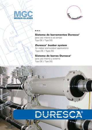
  • 1. N 41.4 Sistema de barramentos Duresca® para uso interno e ao tempo Tipo DE / Tipo DG Duresca® busbar system for indoor and outdoor applications Type DE / Type DG Sistema de barras Duresca® para uso interno y externo Tipo DE / Tipo DG
  • 2. 2 DTOI 123 kV – 1250 A Travesca® Buchas para Transformadores de Potência Transformer-Bushing Bujes para Transformadores de Potencia Tiresca® Sistema de barramentos Busbar System Sistema de barras TE 24 kV – 1250 A Duresca® Buchas de passagem Wall Bushings Bujes pasamuro DM2I 36 kV – 1600 A Duresca® DG-Sistema de barramentos DG-Busbar System DG-Sistema de barras DG 17,5 kV – 2500 A Duresca® DE-Sistema de barramentos DE-Busbar System DE-Sistema de barras DE 17,5 kV – 2500 A GL 12 kV – 2500 A Gaslink® Sistema de barramentos Busbar System Sistema de barras Linha de produtos: Product range: Línea de productos:
  • 3. O sistema de barramentos DURESCA® O condutor é composto de uma liga de alumínio cilíndrico do tipo EN AW-6101B T7 ou de cobre eletrolítico. A isolação é feita no próprio condutor e consiste em papel envolto e seco sob vácuo e impregnação em resina epoxi. Camadas graduais de condutores são inseridas durante o processo de envolvimento do material isolante para controle do campo. Uma blindagem eletrostática em cobre de, no mínimo, 50mm2 é inserida na isolação. Esta é, em caso de falha excepcional, a melhor forma de proteger os operadores durante a instalação. Durante toda a extenção da barra, a superfície dos isoladores é coberta de um tubo pro- tetor. Este tubo garante uma efetiva barreira contra entrada de umidade e também oferece uma ótima proteção contra choques. As barras são produzidas em seções de até 10 metros. Para maiores dis- tâncias ou lugares com espaço físico limitado onde apenas peças pe- quenas podem ser montadas, as conexões são feitas em campo. As ar- ticulações são flexíveis ou rígidas e são também eletricamente blindadas por luvas isoladoras. As barras são feitas de acordo com o projeto do cliente e sua instalação consiste principalmente na facilidade de mon- tagem de peças padronizadas. Conexões para Sistemas Isolados a Gás As conexões de alta corrente e as flanges de vedação são adaptadas para conexão em Sistemas Isolados a Gás Conexão em Transformadores A conexão aos transformadores pode ser isolada ou nua. Para uma conexão com isolação plena, o transformador é equi- pado com buchas óleo-óleo. A conexão da bucha para o barra- mento é protegida por um cilin- dro de isolação. A bucha tem seu desenho elaborado de forma que combine com o transformador de um dos lados e com o cilindro protetor de outro. Por esta razão é preferível e vantajoso que as buchas sejam também da Moser-Glaser. A conexão aberta de um terminal de barramento Duresca para uma bucha de transformador também é possível. As terminações de barra- mentos de uso ao tempo são protegidas por isoladores de porcelana ou silicone similares às buchas de uso externo. Sistema de barramentos 3
  • 4. 4 Tolerância dimensional do comprimento dos barramentos O ajuste das seções ocorre nas luvas de isolação através do uso de conectores flexíveis. Ensaio / Garantia de Qualidade Cada barramento é submetido aos testes de rotina que consistem em: medição da capacitância, tangente delta, descargas parciais tensão suportável nominal à frequência industrial. Cada componente de cone- xão GIS é ainda testado sob pressão para verificação do processo de selagem. Classe de proteção Barramentos IP67. Cilindro e caixas de proteção IP 64 como padrão e IP 68 caso solicitado. Temperatura ambiente permitida –40° até +40° C (outras faixas sob consulta) Descrição dos Barramentos DURESCA® -Schienen, Tipo DE: - instalação interna/interna, externa/interna ou externa/externa - sistema rígido completamente isolado e aterrado - blindagem eletrostática em cobre, incorporado na isolação e projetado para uma falha de 8 kA/1s - alta suportabilidade a curtos-circuitos - livre de descargas parciais - testado em fábrica - projetado conforme necessidade do cliente - design compacto com reduzido raio de curvatura - fácil e rápida instalação - livre de manutenção Os Barramentos DURESCA® estão disponíveis em duas versões: DURESCA® tipo DE O isolamento de proteção é feito por um tubo corrugado de poliamida de alta qualidade (PA12). Além do isolamento, esta superfície corrugada proporciona um incremento na distância de fuga na extremidade do barramento. Esta qualidade de material garante que os barramentos possam ser utilizados tanto em instalações internas quanto externas. O comportamento às severas condições climáticas foi verificado de acordo com a norma ASTM Cd 2565 e testada em laboratório indepen- dente. MGC utiliza este material por mais de 20 anos. DURESCA® tipo DG Em caso de ambientes com atmosfera altamente poluída, o tubo corru- gado protetor de poliamida pode ser substituído por Aço-inoxidável ou Alumínio. Tipos de designações: DE.../DG... ..X = conexão SF6 ..S = conexão plug-in ..I = terminais com isolador em silicone ..P = terminais com isolador em porcelana
  • 5. The DURESCA Busbar System The conductor is made up of a cylindrical aluminium alloy type EN AW-6101B T7, or of an electrolytic copper. The insulation lies directly on the conductor and consists of wrapped paper dried under vacuum and impregnated with EPOXY resin. Conductive grading layers are em- bedded during the wrapping in the insulation for the field control. An earth screen in copper of min. 50 mm2 is embedded in the insulation. It is, in case of an exceptional failure, the best protection for the people and the installation. On the whole lenght of the bar, the surface of the insulation is covered by a protection tube. This tube provides an effec- tive barrier against moisture ingress and an good protection against shocks. The single bars are manufactured in lengths up to 10 meters. For longer bus runs or by tight place conditions where only short pieces can be installed, the single busbars are joined together on site. The joints are flexible or rigid and are also electrically shielded by insulating sleeve. The single bars are custom made and their installation consists mainly of the easy assembly of standard components. Connection to GIS The high current connection and the sealing flange are adapted to the GIS connection. Connection to the transformer The connection to the trans- former can be insulated or bare. For the fully insulated connec- tion, the transformer is equipped with an oil-oil bushing. The bus- bar to bushing connection is pro- tected by an insulating cylinder. The bushing is custom design to match with the transformer on one side and with the insulating cylinder on the other side. For this reason it is advantageous that the bushings are provided by MGC. An open connection from the Duresca bus bar terminal to the transformer bushing terminal is also available. The outdoor ends of the bars are protected by silicone or porce- lain insulators similar to those of outdoor bushings. Busbar System Bahamas 5
  • 6. Dimensional tolerance of the bar length The adjustment of the length occurs in the insulating sleeves through the use of flexible connectors. Testing / Quality assurance Each single bar is subject to a routine test schedule which consists of: measuring of capacitance, tan delta, partial discharges and 50 Hz with- stand voltage test. Each GIS connection part is additionally pressure tested to check its sealing properties. Protection class Busbars IP 67. Cylinder and protection boxes IP 64 as standard, IP 68 on request. Allowed ambient air temperature –40°C up to +40°C (other ranges on request) Description of DURESCA® busbars, type DE: - indoor/indoor, outdoor/indoor or outdoor/outdoor service - solid, separate and fully isolated phase bus - earth screen in copper, embedded in the insulation and designed for an exceptional fault current of 8 kA /1s - high short-circuit capability - partial discharge free operation - factory tested - custom engineered for each individual installation - compact design with reduced bending radius - easy and fast installation - without maintenance The DURESCA busbars are available under 2 executions Type DURESCA® DE The insulation body is protected by a high quality (PA12) corrugated tube in polyamide. Furthermore, the corrugation provides an increase of the creepage distance on the end of the busbar. The selected quality au- thorizes as well an indoor or outdoor use.The good behaviour in the se- vere climatic conditions was checked according to the ASTM Cd 2565 standard and tested in an independant laboratory. MGC has used this type of protection tube for more than 20 years. Type DURESCA® DG In case of particular requirement in an heavely polluted area the polyamid corrugated protection tube could be replaced by one in CrNi- steel or Aluminium. Type designations: DE.../DG... ..X = SF6 connection ..S = Plug in connection ..I = Termination with silicon shed insulator ..P = Termination with porcelain insulator 6
  • 7. El sistema de barras DURESCA® El conductor es compuesto de una liga de alumínio cilíndrico del tipo EN AW-6101B T7 o de cobre electrolítico. La aislación es hecha en el propio conductor y consiste en papel envuelto en seco bajo vacío e impregnación en resina epoxy. Camadas graduales de conductores son inseridas durante el proceso de aislación para mejor contról del campo. Una blindaje electrostática en cobre de, en mínimo, 50mm2 es inserida en la aislación. Esta es, en caso de falta excepcional, la mejor forma de proteger los operadores durante la instalación. Por toda la extención de la barra, la superficie de los aisladores es cobierta con un tubo protec- tor. Este tubo garantiza una efectiva barrera contra la entrada de hume- dad y también ofrece una excelente protección contra choques. Las barras son producidas en secciones de hasta 10 metros. Para distancias más largas o lugares con espacio físico limitado donde sola- mente piezas pequeñas pueden ser ensambladas, las conexiones son hechas en campo. Las articulaciones son flexibles o rígidas y son también electricamente blindadas con protecciones aisladas. Las barras son hechas de acuedo al proyecto del cliente y su instalación consiste principalmente en la facilidad de montaje de las piezas estándares. Conexiones para Sistemas Aislados en Gas Las conexiones de alta corriente y las flanges de vedación son adapta- das para conexión en Sistemas Aislados en Gas. Conexión en Transformadores La conexión a los transformado- res puede ser aislada o desnuda. Para una conexión con aislación plena, el transformador es equi- pado con bujes aceite-aceite. La conexión del buje para la barra es protegida por un cilindro de aisla- ción. El buje tiene su diseño ela- borado de forma que combine con el transformador de un de los lados y con el cilindro protector del otro. Por esta razón es prefe- rible y ventajoso que los bujes sean también de la Moser-Glaser. La co- nexión abierta de un terminal de barra Duresca para un buje de trans- formador también es possible. Las terminaciones de barras de uso externo son protegidas por aisladores de porcelana o silicona similares a los bujes de uso externo. Sistema de barras KW-Wildegg-Brugg 7
  • 8. 8 Tolerancia dimensional de la longitud de las barras El ajuste de las secciones ocurre en las conexiones aisladas a través del uso de conectores flexibles. Prueba / Garantía de Calidad Cada barra es sometida a los testes de rutina que consisten en: medi- ción de la capacitancia, tangente delta, descargas parciales, tensión so- portable nominal a la frecuencia industrial. Cada componente de cone- xión GIS es todavía testado bajo presión para verificación del proceso de sellado. Clase de proteción Barras IP 67. Cilindro y cajas de protección IP 64 como estándar e IP 68 caso solicitado. Temperatura ambiente permitida –40°C hasta +40°C (otras bajo consulta) Descripción de las Barras DURESCA® , tipo DE: - instalación interna/interna, externa/interna o externa/externa - sistema rígido completamente aislado y puesto a tierra - blindaje electrostática en cobre, incorporado en la aislación y proyectado para una falla de 8 kA/1s - alta soportabilidad a los cortoscircuitos - libre de descargas parciales - testado en fábrica - proyectado bajo necesidad del cliente - design compacto con reducido radio de curvatura - fácil y rápida instalación - libre de mantenimiento Las Barras DURESCA® están disponibles en dos versiones DURESCA® tipo DE El aislamiento de protección es hecho por un tubo corrugado de polia- mida de alta calidad (PA12). Además des aislamiento, esta superficie corrugada proporciona un aumento en la distancia de fuga en la extre- midade de la barra. Esta calidad del material garantiza que las barras puedan ser utilizados tanto en instalaciones internas cuanto externas. El comportamiento ante las severas condiciones climáticas fue verifi- cado de acuerdo a la norma ASTM Cd 2565 y testada en laboratorio independente. MGC usa de este material hacen más de 20 años. DURESCA® tipo DG En caso de ambientes con atmósfera altamente contaminada, el tubo corrugado protector de poliamida puede ser sustituido por acero-inoxi- dable o aluminio. Tipos de designaciones: DE.../DG... ..X = conexión SF6 ..S = conexión plug-in ..I = terminales con aislador en silicona ..P = terminales con aislador en porcelana
  • 9. 9 Conectores planos Flat pads Conectores planos Até /Up to / Hasta 1250 A Até /Up to / Hasta 1600 A Até /Up to / Hasta 1600 A Até /Up to / Hasta 2500 A Até /Up to / Hasta 2500 A Até /Up to / Hasta 3150 A Até /Up to / Hasta 3150 A Até /Up to / Hasta 4000 A Até /Up to / Hasta 4000 A Até /Up to / Hasta 5000 A Até /Up to / Hasta 5000 A
  • 10. DURESCA® DE: Alumínio EN AW-6101B T7 1) 2) 3) 4) 5) 6) 7) 8) 9) Un Up Bil In PA Diâmetro Curvatura mínima Peso Capacitância kV kV kV A ∅ mm ∅ mm mm kg/m pf/m 12 / 17,5 28 / 38 75 / 95 1250 55 36 250 4,1 1290 1600 67 45 250 6,2 1400 2000 80 55 250 9 1515 2500 106 80 / 50 400 12 2410 3150 146 110 / 80 550 18,9 2410 24 50 125 1000 55 30 250 3,7 640 1250 67 40 250 5,8 820 1600 80 50 400 8,5 930 2000 106 70 / 40 400 12,4 1005 2500 106 70 / 40 400 12,4 1005 3150 146 110 / 80 550 18,9 1205 36 70 170 800 55 25 250 3,4 425 1250 67 36 250 5,5 595 1600 80 45 250 8 655 2500 106 70 / 40 400 12,4 1005 3150 146 100 / 70 550 16,6 1300 52 95 250 1000 80 36 250 7,2 370 2000 106 60 400 14,4 –– 72,5 140 325 800 80 30 250 6,8 300 1250 106 40 250 12,3 290 1600 106 50 400 13,2 410 2500 146 70 / 40 400 21,4 555 123 230 550 800 146 50 550 — –– 1250 146 50 550 22,8 –– DURESCA® DE: Cobre / Copper / Cobre ETP H 1) 2) 3) 4) 5) 6) 7) 8) 9) Un Up Bil In PA Diâmetro Curvatura mínima Peso Capacitância kV kV kV A ∅ mm ∅ mm mm kg/m pf/m 12 / 17,5 28 / 38 75 / 95 1250 55 32 250 8,8 845 1600 67 40 250 13,6 1405 2000 80 50 400 20,6 876 2500 106 70 / 50 400 22,2 1005 3150 106 80 / 50 400 31,0 2410 4000 146 110 / 90 550 34,7 2410 24 50 125 1250 55 32 250 8,8 845 1600 67 40 250 13,6 820 2000 80 50 400 20,6 930 2500 106 70 / 50 400 22,2 1005 3150 146 80 / 50 400 40 –– 4000 146 110 / 90 550 34,7 2410 36 70 170 1000 55 25 — 6,5 425 1250 67 32 250 10,1 590 1600 80 40 250 15,3 525 2000 106 50 400 25,4 845 2500 106 70 / 50 400 22,2 1005 3150 146 80 / 50 400 40 1133 52 95 250 1250 80 32 250 11,9 332 2000 106 50 400 25,4 406 2500 146 70 / 50 400 31,2 536 3150 146 80 / 50 400 40 555 72,5 140 325 1250 80 32 250 11,9 332 1600 106 50 400 25,4 406 2500 146 70 / 50 400 31,2 536 3150 146 80 / 50 400 40 555 123 230 550 1250 146 45 250 31,6 –– 2000 146 50 400 34,4 –– Notas relacionadas à tabela 1) Tensão nominal 2) Tensão suportável à frequência nominal, 50 Hz, durante 1 minuto, seco 3) Nível básico de impulso, seco, 1,2/50 µs 4) Corrente nominal 5) Diâmetro do tubo de proteção 6) Diâmetro do condutor 7) Raio de curvatura padrão 8) Peso por metro de barramento 9) Capacitância Notes related to table 1) Rated voltage 2) Power frequency withstand voltage test, 50 Hz, 1 minute, dry 3) Dry lightning impulse voltage, 1,2/50 µs 4) Rated current 5) Diameter of the protection tube 6) Diameter of the conductor 7) Standard bend radius 8) Weight per single phase meter 9) Capacity Notas relacionadas a la tabela 1) Tensión nominal 2) Tensión soportable a la frecuencia nominal, 50 Hz, durante 1 minuto, seco 3) Nivel básico de impulso, seco, 1,2/50 µs 4) Corriente nominal 5) Diámetro del tubo de protección 6) Diámetro del conductor 7) Radio de curvatura estándar 8) Peso por metro de barra 9) Capacitancia 10
  • 11. DURESCA® DG: Alumínio EN AW-6101B T7 DURESCA® DG: Cobre / Copper / Cobre ETP H 1) 2) 3) 4) 5) 6) 7) 8) 9) Un Up Bil In DG Diâmetro Curvatura mínima Peso Capacitância kV kV kV A ∅ mm ∅ mm mm kg/m pf/m 12 / 17,5 28 / 38 75 / 95 1600 60 40 250 13,8 2000 80 55 250 25,6 3150 100 80 / 50 400 32,1 4000 130 110 / 90 550 34,4 24 50 125 1600 60 40 250 13,8 2000 80 55 250 25,6 3150 100 80 / 50 400 32,1 4000 130 110 / 90 550 34,4 36 70 170 1250 60 32 250 10,4 1600 80 40 250 17,1 2000 100 55 250 29,6 2500 100 70 / 50 400 23,2 3150 130 80 / 50 400 39,8 52 95 250 1250 80 32 250 13,7 2000 100 55 250 29,6 2500 130 70 / 50 400 30,9 3150 130 80 / 50 400 39,8 72,5 140 325 1250 80 32 250 13,7 1600 100 55 250 29,6 2500 130 70 / 50 400 30,9 3150 130 80 / 50 400 39,8 123 230 550 1250 130 45 250 31,3 2000 130 55 250 37,2 Notas relacionadas à tabela 1) Tensão nominal 2) Tensão suportável à frequência nominal, 50 Hz, durante 1 minuto, seco 3) Nível básico de impulso, seco, 1,2/50 µs 4) Corrente nominal 5) Diâmetro do tubo de proteção 6) Diâmetro do condutor 7) Raio de curvatura padrão 8) Peso por metro de barramento 9) Capacitância Notes related to table 1) Rated voltage 2) Power frequency withstand voltage test, 50 Hz, 1 minute, dry 3) Dry lightning impulse voltage, 1,2/50 µs 4) Rated current 5) Diameter of the protection tube 6) Diameter of the conductor 7) Standard bend radius 8) Weight per single phase meter 9) Capacity Notas relacionadas a la tabela 1) Tensión nominal 2) Tensión soportable a la frecuencia nominal, 50 Hz, durante 1 minuto, seco 3) Nivel básico de impulso, seco, 1,2/50 µs 4) Corriente nominal 5) Diámetro del tubo de protección 6) Diámetro del conductor 7) Radio de curvatura estándar 8) Peso por metro de barra 9) Capacitancia 11 1) 2) 3) 4) 5) 6) 7) 8) 9) Un Up Bil In DG Diâmetro Curvatura mínima Peso Capacitância kV kV kV A ∅ mm ∅ mm mm kg/m pf/m 12 / 17,5 28 / 38 75 / 95 1250 60 40 250 6 1600 70 50 400 8,4 2000 80 60 400 11,4 2500 100 80 / 50 400 8,3 3150 130 110 / 80 550 18,5 4000 160 138 / 106 550 25,5 5000 200 170 / 138 750 36 6300 250 226 / 196 1000 54,4 24 50 125 1000 60 36 250 5,7 1250 70 45 250 7,9 1600 80 55 250 10,8 2000 100 70 / 40 400 13,4 3150 130 110 / 80 550 18,5 4000 160 138 / 106 550 25,5 5000 200 170 / 138 750 36 6300 250 226 / 196 1000 54,4 36 70 170 800 60 36 250 5,7 1250 70 40 250 7,5 1600 80 50 400 10,3 2000 100 70 / 40 400 13,4 2500 130 110 / 80 550 18,5 3150 130 110 / 80 550 18,5 4000 160 138 / 106 550 28,1 5000 200 170 / 138 750 36 6300 250 226 / 196 1000 54,4 52 95 250 1250 80 40 250 9,3 2000 100 60 400 15,5 3150 160 110 / 80 550 28,4 4000 200 138 / 106 750 44,7 5000 250 170 / 138 1000 54,4 72,5 140 325 1250 80 36 250 9 1600 100 50 400 14,3 2500 130 80 / 50 400 20,8 3150 160 110 / 80 550 28,4 4000 200 138 / 106 750 44,7 5000 250 170 / 138 1000 54,4 123 230 550 1600 130 60 400 23,1 2000 160 70 / 40 400 31 4000 200 138 / 106 750 44,7 145 275 650 1250 160 60 400 33 1600 160 70 / 40 400 31 2500 200 110 / 80 750 45 170 325 750 1250 160 60 400 33 2500 200 100 / 70 1000 46 3150 250 138 / 106 1000 78
  • 12. Câmara de expansão Bellows Cámara de expansión d e f g N° de furos Barramentos – ∅ No.of holes Busbars – ∅ N° de agujeros Barras – ∅ 120 150 175 80 8 55 / 67 / 80 160 200 220 80 8 106 200 240 265 110 8 146 LAYOUT·THOMAAG,BASEL Ur L1 L L2 (kV) (mm) (mm) (mm) 12 150 20 170 17,5 180 20 200 24 200 20 220 36 260 40 300 52 400 50 450 72,5 550 50 600 123 1050 100 1150 Aterramento capacitivo (barras) Capacitive earthing (bars) Puesta a tierra capacitivo (barras) a b c N° de furos Barramentos – ∅ No.of holes Busbars – ∅ N° de agujeros Barras – ∅ 110 150 185 4 55 / 67 / 80 130 160 200 4 106 180 220 260 6 146 Barramentos / Busbars / Barras – ∅ 55 / 67 / 80 / 106 Barramentos / Busbars / Barras – ∅ 146 Marcação (linha branca) white mark Marcación (línea blanca) Distância de arco Arcing distance Distancia de arco Flanges de vedação Sealing flanges Flanges de sellado MGC Moser-Glaser AG Lerchenweg 21 CH-4303 Kaiseraugst Suíça / Switzerland Telefon +41 61 467 6111 Telefax +41 61 467 6110 Internet www.mgc.ch E-Mail info@mgc.ch Representada por / Represented by / Representada por: Sujeito à alterações sem aviso prévio / Alterations reserved / Nos reservamos al derecho de hacer revisiones sin aviso previo Duresca Ed 1.0 - 08/11