SlideShare uma empresa Scribd logo
1 de 24
Baixar para ler offline
313
©Copyright 1996 by International Business Machines Corpora-
tion. Copying in printed form for private use is permitted without
payment of royalty provided that (1) each reproduction is done
without alteration and (2) the Journal reference and IBM copyright
notice are included on the first page. The title and abstract, but no
other portions, of this paper may be copied or distributed royalty
free without further permission by computer-based and other infor-
mation-service systems. Permission to republish any other portion
of this paper must be obtained from the Editor.
IBM SYSTEMS JOURNAL, VOL 35, NOS 3&4, 1996 0018-8670/96/$5.00 © 1996 IBM BENDER ET AL.
Data hiding, a form of steganography, embeds
data into digital media for the purpose of
identification, annotation, and copyright. Several
constraints affect this process: the quantity of
data to be hidden, the need for invariance of these
data under conditions where a “host” signal is
subject to distortions, e.g., lossy compression,
and the degree to which the data must be immune
to interception, modification, or removal by a third
party. We explore both traditional and novel
techniques for addressing the data-hiding process
and evaluate these techniques in light of three
applications: copyright protection, tamper-
proofing, and augmentation data embedding.
igital representation of media facilitates access
and potentially improves the portability, effi-
ciency, and accuracy of the information presented.
Undesirable effects of facile data access include an
increased opportunity for violation of copyright and
tampering with or modification of content. The moti-
vation for this work includes the provision of protec-
tion of intellectual property rights, an indication of
content manipulation, and a means of annotation.
Data hiding represents a class of processes used to
embed data, such as copyright information, into vari-
ous forms of media such as image, audio, or text with
a minimum amount of perceivable degradation to the
“host” signal; i.e., the embedded data should be invis-
ible and inaudible to a human observer. Note that data
hiding, while similar to compression, is distinct from
encryption. Its goal is not to restrict or regulate access
to the host signal, but rather to ensure that embedded
data remain inviolate and recoverable.
Two important uses of data hiding in digital media are
to provide proof of the copyright, and assurance of
content integrity. Therefore, the data should stay hid-
den in a host signal, even if that signal is subjected to
manipulation as degrading as filtering, resampling,
cropping, or lossy data compression. Other applica-
tions of data hiding, such as the inclusion of augmen-
tation data, need not be invariant to detection or
removal, since these data are there for the benefit of
both the author and the content consumer. Thus, the
techniques used for data hiding vary depending on the
quantity of data being hidden and the required invari-
ance of those data to manipulation. Since no one
method is capable of achieving all these goals, a class
of processes is needed to span the range of possible
applications.
The technical challenges of data hiding are formida-
ble. Any “holes” to fill with data in a host signal,
either statistical or perceptual, are likely targets for
removal by lossy signal compression. The key to suc-
cessful data hiding is the finding of holes that are not
suitable for exploitation by compression algorithms.
A further challenge is to fill these holes with data in a
way that remains invariant to a large class of host sig-
nal transformations.
D
Techniques for data
hiding
by W. Bender
D. Gruhl
N. Morimoto
A. Lu
BENDER ET AL. IBM SYSTEMS JOURNAL, VOL 35, NOS 3&4, 1996314
Features and applications
Data-hiding techniques should be capable of embed-
ding data in a host signal with the following restric-
tions and features:
1. The host signal should be nonobjectionally
degraded and the embedded data should be mini-
mally perceptible. (The goal is for the data to
remain hidden. As any magician will tell you, it is
possible for something to be hidden while it
remains in plain sight; you merely keep the person
from looking at it. We will use the words hidden,
inaudible, imperceivable, and invisible to mean
that an observer does not notice the presence of the
data, even if they are perceptible.)
2. The embedded data should be directly encoded
into the media, rather than into a header or wrap-
per, so that the data remain intact across varying
data file formats.
3. The embedded data should be immune to modifi-
cations ranging from intentional and intelligent
attempts at removal to anticipated manipulations,
e.g., channel noise, filtering, resampling, cropping,
encoding, lossy compressing, printing and scan-
ning, digital-to-analog (D/A) conversion, and ana-
log-to-digital (A/D) conversion, etc.
4. Asymmetrical coding of the embedded data is
desirable, since the purpose of data hiding is to
keep the data in the host signal, but not necessarily
to make the data difficult to access.
5. Error correction coding1
should be used to ensure
data integrity. It is inevitable that there will be
some degradation to the embedded data when the
host signal is modified.
6. The embedded data should be self-clocking or
arbitrarily re-entrant. This ensures that the embed-
ded data can be recovered when only fragments of
the host signal are available, e.g., if a sound bite is
extracted from an interview, data embedded in the
audio segment can be recovered. This feature also
facilitates automatic decoding of the hidden data,
since there is no need to refer to the original host
signal.
Applications. Trade-offs exist between the quantity
of embedded data and the degree of immunity to host
signal modification. By constraining the degree of
host signal degradation, a data-hiding method can
operate with either high embedded data rate, or high
resistance to modification, but not both. As one
increases, the other must decrease. While this can be
shown mathematically for some data-hiding systems
such as a spread spectrum, it seems to hold true for all
data-hiding systems. In any system, you can trade
bandwidth for robustness by exploiting redundancy.
The quantity of embedded data and the degree of host
signal modification vary from application to applica-
tion. Consequently, different techniques are employed
for different applications. Several prospective applica-
tions of data hiding are discussed in this section.
An application that requires a minimal amount of
embedded data is the placement of a digital water
mark. The embedded data are used to place an indica-
tion of ownership in the host signal, serving the same
purpose as an author’s signature or a company logo.
Since the information is of a critical nature and the
signal may face intelligent and intentional attempts to
destroy or remove it, the coding techniques used must
be immune to a wide variety of possible modifica-
tions.
A second application for data hiding is tamper-proof-
ing. It is used to indicate that the host signal has been
modified from its authored state. Modification to the
embedded data indicates that the host signal has been
changed in some way.
A third application, feature location, requires more
data to be embedded. In this application, the embed-
ded data are hidden in specific locations within an
image. It enables one to identify individual content
features, e.g., the name of the person on the left versus
the right side of an image. Typically, feature location
data are not subject to intentional removal. However,
it is expected that the host signal might be subjected
to a certain degree of modification, e.g., images are
routinely modified by scaling, cropping, and tone-
scale enhancement. As a result, feature location data-
hiding techniques must be immune to geometrical and
nongeometrical modifications of a host signal.
Trade-offs exist between
the quantity of data and
the immunity to
modification.
IBM SYSTEMS JOURNAL, VOL 35, NOS 3&4, 1996 BENDER ET AL. 315
Image and audio captions (or annotations) may
require a large amount of data. Annotations often
travel separately from the host signal, thus requiring
additional channels and storage. Annotations stored in
file headers or resource sections are often lost if the
file format is changed, e.g., the annotations created in
a Tagged Image File Format (TIFF) may not be present
when the image is transformed to a Graphic Inter-
change Format (GIF). These problems are resolved by
embedding annotations directly into the data structure
of a host signal.
Prior work. Adelson2
describes a method of data hid-
ing that exploits the human visual system’s varying
sensitivity to contrast versus spatial frequency. Adel-
son substitutes high-spatial frequency image data for
hidden data in a pyramid-encoded still image. While
he is able to encode a large amount of data efficiently,
there is no provision to make the data immune to
detection or removal by typical manipulations such as
filtering and rescaling. Stego,3
one of several widely
available software packages, simply encodes data in
the least-significant bit of the host signal. This tech-
nique suffers from all of the same problems as Adel-
son’s method but creates an additional problem of
degrading image or audio quality. Bender4
modifies
Adelson’s technique by using chaos as a means to
encrypt the embedded data, deterring detection, but
providing no improvement to immunity to host signal
manipulation. Lippman5
hides data in the chromi-
nance channel of the National Television Standards
Committee (NTSC) television signal by exploiting the
temporal over-sampling of color in such signals. Typi-
cal of Enhanced Definition Television Systems, this
method encodes a large amount of data, but the data
are lost to most recording, compression, and transcod-
ing processes. Other techniques, such as Hecht’s
Data-Glyph,6 which adds a bar code to images, are
engineered in light of a predetermined set of geomet-
ric modifications.7 Spread-spectrum,8-11 a promising
technology for data hiding, is difficult to intercept and
remove but often introduces perceivable distortion
into the host signal.
Problem space. Each application of data hiding
requires a different level of resistance to modification
and a different embedded data rate. These form the
theoretical data-hiding problem space (see Figure 1).
There is an inherent trade-off between bandwidth and
“robustness,” or the degree to which the data are
immune to attack or transformations that occur to the
host signal through normal usage, e.g., compression,
resampling, etc. The more data to be hidden, e.g., a
caption for a photograph, the less secure the encoding.
The less data to be hidden, e.g., a watermark, the more
secure the encoding.
Data hiding in still images
Data hiding in still images presents a variety of chal-
lenges that arise due to the way the human visual sys-
tem (HVS) works and the typical modifications that
images undergo. Additionally, still images provide a
relatively small host signal in which to hide data. A
fairly typical 8-bit picture of 200 × 200 pixels pro-
vides approximately 40 kilobytes (kB) of data space
in which to work. This is equivalent to only around 5
seconds of telephone-quality audio or less than a sin-
gle frame of NTSC television. Also, it is reasonable to
expect that still images will be subject to operations
ranging from simple affine transforms to nonlinear
transforms such as cropping, blurring, filtering, and
lossy compression. Practical data-hiding techniques
need to be resistant to as many of these transforma-
tions as possible.
Despite these challenges, still images are likely candi-
dates for data hiding. There are many attributes of the
HVS that are potential candidates for exploitation in a
data-hiding system, including our varying sensitivity
to contrast as a function of spatial frequency and the
masking effect of edges (both in luminance and
Figure 1 Conceptual data-hiding problem space
ROBUSTNESS
BANDWIDTH
EXTENT OF CURRENT TECHNIQUES
BENDER ET AL. IBM SYSTEMS JOURNAL, VOL 35, NOS 3&4, 1996316
chrominance). The HVS has low sensitivity to small
changes in luminance, being able to perceive changes
of no less than one part in 30 for random patterns.
However, in uniform regions of an image, the HVS
is more sensitive to the change of the luminance,
approximately one part in 240. A typical CRT (cathode
ray tube) display or printer has a limited dynamic
range. In an image representation of one part in 256,
e.g., 8-bit gray levels, there is potentially room to hide
data as pseudorandom changes to picture brightness.
Another HVS “hole” is our relative insensitivity to
very low spatial frequencies such as continuous
changes in brightness across an image, i.e., vignett-
ing. An additional advantage of working with still
images is that they are noncausal. Data-hiding tech-
niques can have access to any pixel or block of pixels
at random.
Using these observations, we have developed a variety
of techniques for placing data in still images. Some
techniques are more suited to dealing with small
amounts of data, while others to large amounts. Some
techniques are highly resistant to geometric modifica-
tions, while others are more resistant to nongeometric
modifications, e.g., filtering. We present methods that
explore both of these areas, as well as their combina-
tion.
Low bit-rate data hiding
With low bit-rate encoding, we expect a high level of
robustness in return for low bandwidth. The emphasis
is on resistance to attempts of data removal by a third
party. Both a statistical and a perceptual technique are
discussed in the next sections on Patchwork, texture,
and applications.
Patchwork: A statistical approach
The statistical approach, which we refer to as Patch-
work, is based on a pseudorandom, statistical process.
Patchwork invisibly embeds in a host image a specific
statistic, one that has a Gaussian distribution. Figure 2
shows a single iteration in the Patchwork method.
Two patches are chosen pseudorandomly, the first A,
the second B. The image data in patch A are lightened
while the data in patch B are darkened (exaggerated
for purposes of this illustration). This unique statistic
indicates the presence or absence of a signature.
Patchwork is independent of the contents of the host
image. It shows reasonably high resistance to most
nongeometric image modifications.
For the following analysis, we make the following
simplifying assumptions (these assumptions are not
limiting, as is shown later): We are operating in a 256
level, linearly quantized system starting at 0; all
brightness levels are equally likely; all samples are
independent of all other samples.
The Patchwork algorithm proceeds as follows: take
any two points, A and B, chosen at random in an
image. Let a equal the brightness at point A and b the
brightness at point B. Now, let
(1)
The expected value of S is 0, i.e., the average value of
S after repeating this procedure a large number of
times is expected to be 0.
S a b–=
Figure 2 A single iteration in the Patchwork method
(photograph courtesy of Webb Chapel)
IBM SYSTEMS JOURNAL, VOL 35, NOS 3&4, 1996 BENDER ET AL. 317
Although the expected value is 0, this does not tell us
much about what S will be for a specific case. This is
because the variance is quite high for this procedure.
The variance of S, σs is a measure of how tightly sam-
ples of S will cluster around the expected value of 0.
To compute this, we make the following observation:
Since S = a − b and a and b are assumed independent,
can be computed as follows (this, and all other
probability equations are from Drake12):
(2)
where for a uniform S is:
(3)
Now, since a and b are samples from the
same set, taken with replacement. Thus:
(4)
which yields a standard deviation σS ≈ 104. This
means that more than half the time, S will be greater
than 43 or less than − 43. Assuming a Gaussian clus-
tering, a single iteration does not tell us much. How-
ever, this is not the case if we perform the procedure
many times.
Let us repeat this procedure n times, letting ai and bi
be the values a and b take on during the ith iteration,
Si. Now let Sn be defined as:
(5)
The expected value of Sn is:
(6)
This makes intuitive sense, since the number of times
ai is greater than bi should be offset by the number of
times the reverse is true. Now the variance is:
(7)
And the standard deviation is:
(8)
Now, we can compute S10000 for a picture, and if it var-
ies by more than a few standard deviations, we can be
fairly certain that this did not happen by chance. In
fact, since as we will show later S′n for large n has a
Gaussian distribution, a deviation of even a few σS′s
indicates to a high degree of certainty the presence of
encoding (see Table 1).
The Patchwork method artificially modifies S for a
given picture, such that S′n is many deviations away
from expected. To encode a picture, we:
1. Use a specific key for a known pseudorandom
number generator to choose (ai, bi). This is impor-
tant, because the encoder needs to visit the same
points during decoding.
2. Raise the brightness in the patch ai by an amount δ,
typically in the range of 1 to 5 parts in 256.
3. Lower the brightness in bi by this same amount δ
(the amounts do not have to be the same, as long as
they are in opposite directions).
4. Repeat this for n steps (n typically ~10 000).
Now, when decoded, S′n will be:
(9)
or:
(10)
So each step of the way we accumulate an expectation
of 2 × δ. Thus after n repetitions, we expect S′n to be:
σS
2
σS
2
σa
2
σb
2
+=
σa
2
σa
2
5418≈
σa
2
σb
2
=
σS
2
2 σ× a
2
2
255 0–( )2
12
------------------------× 10836≈ ≈=
Sn Si
i 1=
n
∑ ai bi–
i 1=
n
∑= =
Sn n S× n 0× 0= = =
σSn
2
n σS
2
×=
σSn
n σ× n 104×≈=
Sn
′ ai δ+( ) bi δ–( )–
i 1=
n
∑=
Sn
′ 2δn ai bi–( )
i 1=
n
∑+=
Table 1 Degree of certainty of encoding given deviation
from that expected in a Gaussian distribution
(δ = 2)
Standard
Deviations
Away
Certainty n
0
1
2
3
50.00%
84.13%
97.87%
99.87%
0
679
2713
6104
BENDER ET AL. IBM SYSTEMS JOURNAL, VOL 35, NOS 3&4, 1996318
(11)
As n or δ increases, the distribution of S′n shifts over
to the right (Figure 3 and Table 1). In Figure 3, as δ or
n increases, the distribution of S′n shifts further to the
right. If we shift it far enough, any point that is likely
to fall into one distribution is highly unlikely to be
near the center of the other distribution.
While this basic method works well by itself, we have
made a number of modifications to improve perfor-
mance including:
1. Treating patches of several points rather than sin-
gle points. This has the effect of shifting the noise
introduced by Patchwork into the lower spatial fre-
quencies, where it is less likely to be removed by
lossy compression and typical Finite Impulse
Response (FIR) filters.
2. Making Patchwork more robust by using a combi-
nation with either affine coding (described later) or
some heuristic based upon feature recognition
(e.g., alignment using the interocular line of a
face). Patchwork decoding is sensitive to affine
transformations of the host image. If the points in
the picture visited during encoding are offset by
translation, rotation, or scaling before decoding,
the code is lost.
3. Taking advantage of the fact that Patchwork is
fairly resistant to cropping. By disregarding points
outside of the known picture area, Patchwork
degrades in accuracy approximately as the log of
the picture size. Patchwork is also resistant to
gamma and tone scale correction since values of
comparable luminance move roughly the same
way under such modifications.
Patch shape. The shape of the patches deserves some
comment. Figure 4 shows three possible one-dimen-
sional patch shapes, and next to them a very approxi-
mate spectrum of what a line with these patches
dropped onto it pseudorandomly would look like. In
Figure 4A, the patch is very small, with sharp edges.
This results in the majority of the energy of the patch
being concentrated in the high frequency portion of
the image spectrum. This makes the distortion hard to
see, but also makes it a likely candidate for removal
by lossy compressors. If one goes to the other
extreme, as in Figure 4B, the majority of the informa-
tion is contained in the low-frequency spectrum. The
2δn
σSn
′
--------- 0.028δ n≈Figure 3 As δ or n increases, the distribution of S´n
shifts further to the right.
0 4 TO 8 STANDARD DEVIATIONS
Figure 4 The contour of a patch largely determines
which frequencies will be modified by the
application of Patchwork.
π0
(A)
(B)
(C)
PATCH
MODIFIED
π
π
0
0
FREQUENCIES
Figure 5 Patch placement affects patch visibility.
RECTILINEAR HEXAGONAL RANDOM
(A) (B) (C)
IBM SYSTEMS JOURNAL, VOL 35, NOS 3&4, 1996 BENDER ET AL. 319
last choice, Figure 4C shows a wide, sharp-edged
patch, which tends to distribute the energy around the
entire frequency spectrum.
The optimal choice of patch shape is dependent upon
the expected image modifications. If JPEG (Joint Pho-
tographic Experts Group) encoding is likely, then a
patch that places its energy in the low frequencies is
preferable. If contrast enhancement is to be done,
placing energy in higher frequencies would be better.
If the potential image modifications are unknown,
then spreading the patch energy across the spectrum
would make sense.
The arrangement of patches has an impact on patch
visibility. For illustration, three possibilities are con-
sidered (Figure 5). The simplest method is shown in
Figure 5A, a simple rectilinear lattice. While simple,
this arrangement is often a poor choice if a high n is to
be used. As the grid is filled in, continuous edges of
gradient are formed. The HVS is very sensitive to such
edges. A second choice, Figure 5B breaks this sym-
metry by using hexagons for the patch shape. A pre-
ferred solution, shown in Figure 5C, is a completely
random placement of patches. An intelligent selection
of patch shape in both the horizontal and vertical
dimensions will enhance the effectiveness of patch-
work for a given picture.
Uniformity. A simplifying assumption of a uniform
luminance histogram was made above, but this is not
a requirement of Patchwork. The only assumption
Patchwork makes is that the expected value of Si = ai −
bi is zero.
It can be shown that this condition is always met
through the following argument:
1. Let ar be the time reversed series of a.
2. Ar = A*
by definition (A*
is the complex conjugate
of A).
3. F(a∗ar) = AA*
(F is the Fourier transform).
4. AA*
is everywhere real by definition of the com-
plex conjugate.
5. F–1
(AA*
) is even by definition.
6. Even sequences are symmetric around zero by def-
inition.
An image histogram (Figure 6, top) is a somewhat
random distribution. The result of taking the complex
conjugate (Figure 6, bottom) is symmetric around
zero.
Figure 6 A histogram of Figure 2 and its autocorrelation
Figure 7 A histogram of the variance of the luminance
of 365 Associated Press photos from
March 1996
0 2 4 6 8 10 12 14 16
500000
450000
400000
350000
300000
250000
200000
150000
100000
50000
0
–15 –10 –5 0 5 10 15
2.5e+11
2e+11
1.5e+11
1e+11
5e+10
0
0 2000 4000 6000 8000
50
45
40
35
30
25
20
15
10
5
0
10000
VARIANCE FROM
(5418)
EQUATION 3
BENDER ET AL. IBM SYSTEMS JOURNAL, VOL 35, NOS 3&4, 1996320
Variance. When searching through a large number of
images with data embedded using the Patchwork
method, such as when a robot is looking for copyright
violations on the Internet World Wide Web (WWW),
the use of a generic estimation of variance is desir-
able. This avoids the necessity of calculating the vari-
ance of every image. Suspect images can then be
examined thoroughly.
When, in the analysis above, the number of points
needed in Equation 3 was computed, the variance of
the luminance was assumed to be 5418. This assump-
tion turns out to be higher than the average observed
values (see Figure 7). The question is, then, what
value should be used.
An examination of the variance of 365 Associated
Press photos from March 1996 yielded an average
value of 3877.4 and a distribution that can be seen in
Figure 7. While some pictures do have variances as
high as two-thirds of the maximum, most are clus-
tered around the lower variance values. Thus, 5418,
the estimate derived from the uniformity assumption,
is a conservative but reasonable value to use for a
generic picture.
A minimum value is that for a solid color picture (Fig-
ure 8A). This has a variance of 0, a standard deviation
of 0, and thus works very well for Patchwork, since
any modification is evident. The other extreme is that
of a two-color, black and white picture. For these, the
variance is:
(12)
These two values, 0 and 16256, define the extremes of
the variance to consider when calculating the likeli-
hood that a picture is encoded. What is the correct
assumption to use for a given picture? The actual vari-
ance of the picture being examined is a sensible
choice, since in most cases Patchwork will increase
the variance only slightly. (This depends on the size
and depth of the patch, the number of patches, and the
histogram of the original image.) However, if a large
number of pictures are to examined, a generic value is
a practical choice.
Summary. There are several limitations inherent to
the Patchwork technique. The first is the extremely
low embedded data rate it yields, usually a one-bit
signature per image. This limits its usefulness to low
bit-rate applications such as the digital watermark.
Second, it is necessary to register where the pixels in
the image lie. While a number of methods have been
investigated, it is still somewhat difficult to decode the
image in the presence of severe affine transforma-
tions. These disadvantages aside, without the key for
the pseudorandom number generator, it is extremely
difficult to remove the Patchwork coding without
degrading the picture beyond recognition.
The Patchwork method is subject to cryptographic
attack if it is used to encode a large number of identi-
cally sized images using the same key. If the images
are averaged together, the patches will show up as
lighter or darker than average regions. This weakness
is a common one in cryptography, and points to the
truism that for a static key, as the amount of traffic
increases, it becomes easier to “crack” the encryption.
One solution is to use multiple pseudorandom pat-
terns for the patches. Even the use of just two keys,
while increasing decoding time, will make Patchwork
much more robust to attack. Another solution is to use
the same pattern, but to reverse the polarity of the
patches. Both solutions deter cryptographic attack by
averaging.
Texture Block Coding: A visual approach
A second method for low bit-rate data hiding in
images is Texture Block Coding. This method hides
data within the continuous random texture patterns of
a picture. The Texture Block Coding technique is
0 127–( )
2
2
------------------------
255 127.5–( )
2
2
-----------------------------------+ 16256≈Figure 8 Histograms of pictures with minimum (A) and
maximum (B) variance
MIN MAXANY
(A) (B)
IBM SYSTEMS JOURNAL, VOL 35, NOS 3&4, 1996 BENDER ET AL. 321
implemented by copying a region from a random tex-
ture pattern found in a picture to an area that has simi-
lar texture. This results in a pair of identically textured
regions in the image (see Figure 9).
These regions can be detected as follows:
1. Autocorrelate the image with itself. This will pro-
duce peaks at every point in the autocorrelation
where identical regions of the image overlap. If
large enough areas of an image are copied, this
will produce an additional large autocorrelation
peak at the correct alignment for decoding.
2. Shift the image as indicated by the peaks in Step 1.
Now subtract the image from its shifted copy, pad-
ding the edges with zeros as needed.
3. Square the result and threshold it to recover only
those values quite close to zero. The copied region
will be visible as these values.
Since the two regions are identical, they are modified
in the same way if the picture is uniformly trans-
formed. By making the regions reasonably large, the
inner part of the block changes identically under most
nongeometric transformations. In our experiments,
coded 16 × 16 pixel blocks can be decoded when the
picture is subjected to a combination of filtering, com-
pression, and rotation.
Texture Block Coding is not without its disadvan-
tages. Currently it requires a human operator to
choose the source and destination regions, and to eval-
uate the visual impact of the modifications on the
image. It should be possible to automate this process
by allowing a computer to identify possible texture
regions in the image to copy from and paste to. How-
ever, this technique will not work on images that lack
moderately large areas of continuous texture from
which to draw.
Figure 9 Texture Block Coding example (photograph courtesy of Webb Chapel)
BENDER ET AL. IBM SYSTEMS JOURNAL, VOL 35, NOS 3&4, 1996322
Future research in this area includes the possibility of
cutting and pasting blocks from only part of the image
frequency spectrum (this would allow less noticeable
blocks to be moved around, and a final encoding that
is considerably more robust to various image com-
pression algorithms) along with automatic texture
region selection and analysis of perceivability of the
final result.
High bit-rate coding
High bit-rate methods can be designed to have mini-
mal impact upon the perception of the host signal, but
they do not tend to be immune to image modifica-
tions. In return, there is an expectation that a relatively
large amount of data are able to be encoded. The most
common form of high bit-rate encoding is the replace-
ment of the least significant luminance bit of image
data with the embedded data. Other techniques
include the introduction of high-frequency, low-
amplitude noise and the use of direct sequence spread
spectrum coding. All high bit-rate methods can be
made more robust through the use of error-correction
coding, at the expense of data rate. High bit-rate codes
are only appropriate where it is reasonable to expect
that a great deal of control will be maintained over the
images.
Individually, none of the known techniques for data
hiding are resistant to all possible transforms or com-
binations of transforms. In combination, often one
technique can supplement another. Supplementary
techniques are particularly important for recovery
from geometric modifications such as affine transfor-
mations, and maintaining synchronization for spread-
spectrum encoding.
Affine coding. Some of the data-hiding techniques,
such as Patchwork, are vulnerable to affine trans-
forms. It makes sense to develop methods that can be
used to facilitate the recovery of embedded data after
affine application. Affine coding is one such method:
A predefined reference pattern is embedded into a
host image using any of the high bit-rate coding tech-
niques. Estimation of geometric transformation of the
image is achieved by comparing the original shape,
size, and orientation of the reference pattern to that
found in the transformed image. Since affine trans-
forms are linear, the inverse transform can be applied
to recover the original image. Once this is done, the
image is ready for further extraction of embedded
data.
Applications
Placing data in images is useful in a variety of appli-
cations. We highlight below four applications that dif-
fer in the quantity of data to be embedded and the type
of transforms to which the data are likely to be sub-
jected.
Digital watermark. The objective of a digital water-
mark is to place an indelible mark on an image. Usu-
ally, this means encoding only a handful of bits,
sometimes as few as one. This “signature” could be
used as a means of tracing the distribution of images
for an on-line news service and for photographers
who are selling their work for digital publication. One
could build a digital camera that places a watermark
on every photograph it takes. Theoretically, this
would allow photographers to employ a “web-search-
ing agent” to locate sites where their photographs
appear.
It can be expected that if information about legal own-
ership is to be included in an image, it is likely that
someone might want to remove it. A requirement of a
digital watermark is that it must be difficult to remove.
Both the Patchwork and Texture Block Coding tech-
niques show promise as digital watermarks. Patch-
work, being the more secure of the two, answers the
question “Is this my picture?” Texture Block Coding,
which can be made readily accessible to the public,
answers the question “Whose picture is this?”
Figure 10 Characterizing the difference between
tamper-proofing and other data-hiding
techniques
EFFORT
(A) (B)
MODIFICATION
IBM SYSTEMS JOURNAL, VOL 35, NOS 3&4, 1996 BENDER ET AL. 323
Tamper-proofing. The objective of tamper-proofing
is to answer the question, “Has this image been modi-
fied?” Tamper-proofing techniques are related, but
distinct from the other data-hiding technologies. What
differentiates them is the degree to which information
is secured from the host signal. In Figure 10, the dif-
ference between tamper-proofing and other data-hid-
ing techniques is characterized. Figure 10A illustrates
that data hiding requires a deep information well that
is resilient to large displacements. Figure 10B illus-
trates that tamper-proofing requires a shallow well
that is only resilient to small displacements, but is
triggered by large displacements. Most data-hiding
techniques attempt to secure data in the face of all
modifications. Tamper-proofing techniques must be
resilient to small modifications (e.g., cropping, tone-
scale or gamma correction for images or balance or
equalization for sounds) but not to large modifications
(e.g., removing or inserting people from an image or
taking words out of context in an audio recording).
There are several ways to implement tamper-proofing.
The easiest way is to encode a check-sum of the
image within the image. However, this method is trig-
gered by small changes in the image. This suggests an
approach involving a pattern overlaid on the image.
The key to a successful overlay is to find a pattern
resilient to simple modifications such as filtering and
gamma correction, yet is not easily removed. The
search for such patterns and other methods of detect-
ing tampering remains an active area of research.
Feature tagging. Another application of data hiding
is tagging the location of features within an image.
Using data hiding it is possible for an editor (or
machine) to encode descriptive information, such as
the location and identification of features of interest,
directly into specific regions of an image. This
enables retrieval of the descriptive information wher-
ever the image goes. Since the embedded information
is spatially located in the image, it is not removed
unless the feature of interest is removed. It also trans-
lates, scales, and rotates exactly as the feature of inter-
est does.
This application does not have the same requirements
for robustness as the digital watermark. It can be
assumed that, since feature location is providing a ser-
vice, it is unlikely someone will maliciously try to
remove the encoded information.
Embedded captions. Typical news photograph cap-
tions contain one kB of data. Thus embedded captions
is a relatively high bit-rate application for data hiding.
As with feature tagging, caption data are usually not
subject to malicious removal.
While captions are useful by themselves, they become
even more useful when combined with feature loca-
tion. It is then possible for portions of the caption to
directly reference items in the picture. Captions can
become self-editing once this is done. If an item refer-
enced in the caption is cropped out of the picture, then
the reference to that item in the caption can be
removed automatically.
Data hiding in audio
Data hiding in audio signals is especially challenging,
because the human auditory system (HAS) operates
over a wide dynamic range. The HAS perceives over a
range of power greater than one billion to one and a
range of frequencies greater than one thousand to one.
Sensitivity to additive random noise is also acute. The
perturbations in a sound file can be detected as low as
one part in ten million (80 dB below ambient level).
However, there are some “holes” available. While the
HAS has a large dynamic range, it has a fairly small
differential range. As a result, loud sounds tend to
mask out quiet sounds. Additionally, the HAS is
unable to perceive absolute phase, only relative phase.
Finally, there are some environmental distortions so
common as to be ignored by the listener in most
cases.
We exploit many of these traits in the methods we dis-
cuss next, while being careful to bear in mind the
extreme sensitivities of the HAS.
Audio environments
When developing a data-hiding method for audio, one
of the first considerations is the likely environments
the sound signal will travel between encoding and
decoding. There are two main areas of modification
which we will consider. First, the storage environ-
ment, or digital representation of the signal that will
be used, and second the transmission pathway the sig-
nal might travel.
Digital representation. There are two critical param-
eters to most digital audio representations: sample
quantization method and temporal sampling rate.
The most popular format for representing samples of
high-quality digital audio is a 16-bit linear quantiza-
BENDER ET AL. IBM SYSTEMS JOURNAL, VOL 35, NOS 3&4, 1996324
tion, e.g., Windows Audio-Visual (WAV) and Audio
Interchange File Format (AIFF). Another popular for-
mat for lower quality audio is the logarithmically
scaled 8-bit µ-law. These quantization methods intro-
duce some signal distortion, somewhat more evident
in the case of 8-bit µ-law.
Popular temporal sampling rates for audio include
8 kHz (kilohertz), 9.6 kHz, 10 kHz, 12 kHz, 16 kHz,
22.05 kHz, and 44.1 kHz. Sampling rate impacts data
hiding in that it puts an upper bound on the usable
portion of the frequency spectrum (if a signal is sam-
pled at ~8 kHz, you cannot introduce modifications
that have frequency components above ~4 kHz). For
most data-hiding techniques we have developed,
usable data space increases at least linearly with
increased sampling rate.
A last representation to consider is that produced by
lossy, perceptual compression algorithms, such as the
International Standards Organization Motion Pictures
Expert Group—Audio (ISO MPEG-AUDIO) perceptual
encoding standard. These representations drastically
change the statistics of the signal; they preserve only
the characteristics that a listener perceives (i.e., it will
sound similar to the original, even if the signal is com-
pletely different in a least squares sense).
Transmission environment. There are many differ-
ent transmission environments that a signal might
experience on its way from encoder to decoder. We
consider four general classes for illustrative purposes
(see Figure 11). The first is the digital end-to-end
environment (Figure 11A). This is the environment of
a sound file that is copied from machine to machine,
but never modified in any way. As a result, the sam-
pling is exactly the same at the encoder and decoder.
This class puts the least constraints on data-hiding
methods.
The next consideration is when a signal is resampled
to a higher or lower sampling rate, but remains digital
throughout (Figure 11B). This transform preserves the
absolute magnitude and phase of most of the signal,
but changes the temporal characteristics of the signal.
The third case is when a signal is “played” into an
analog state, transmitted on a reasonably clean analog
line and resampled (Figure 11C). Absolute signal
magnitude, sample quantization, and temporal sam-
pling rate are not preserved. In general, phase will be
preserved.
The last case is when the signal is “played into the
air” and “resampled with a microphone” (Figure
11D). The signal will be subjected to possibly
unknown nonlinear modifications resulting in phase
changes, amplitude changes, drift of different fre-
quency components, echoes, etc.
Signal representation and transmission pathway must
be considered when choosing a data-hiding method.
Data rate is very dependent on the sampling rate and
the type of sound being encoded. A typical value is
16 bps, but the number can range from 2 bps to
128 bps.
Low-bit coding
Low-bit coding is the simplest way to embed data into
other data structures. By replacing the least significant
bit of each sampling point by a coded binary string,
we can encode a large amount of data in an audio sig-
nal. Ideally, the channel capacity is 1 kb per second
(kbps) per 1 kilohertz (kHz), e.g., in a noiseless chan-
Figure 11 Transmission environments
SOURCE
SOURCE
SOURCE
SOURCE
DESTINATION
DIGITAL
RESAMPLED
ANALOG
“OVER THE AIR”
(A)
(B)
(C)
(D)
DESTINATION
DESTINATION
DESTINATION
IBM SYSTEMS JOURNAL, VOL 35, NOS 3&4, 1996 BENDER ET AL. 325
nel, the bit rate will be 8 kbps in an 8 kHz sampled
sequence and 44 kbps in a 44 kHz sampled sequence.
In return for this large channel capacity, audible noise
is introduced. The impact of this noise is a direct
function of the content of the host signal, e.g., crowd
noise during a live sports event would mask low-bit
encoding noise that would be audible in a string quar-
tet performance. Adaptive data attenuation has been
used to compensate this variation.
The major disadvantage of this method is its poor
immunity to manipulation. Encoded information can
be destroyed by channel noise, resampling, etc.,
unless it is encoded using redundancy techniques. In
order to be robust, these techniques reduce the data
rate, often by one to two orders of magnitude. In prac-
tice, this method is useful only in closed, digital-to-
digital environments.
Phase coding
The phase coding method works by substituting the
phase of an initial audio segment with a reference
phase that represents the data. The phase of subse-
quent segments is adjusted in order to preserve the
relative phase between segments.
Phase coding, when it can be used, is one of the most
effective coding methods in terms of the signal-to-
perceived noise ratio. When the phase relation
between each frequency component is dramatically
changed, a noticeable phase dispersion will occur.
However, as long as the modification of the phase is
sufficiently small (sufficiently small depends on the
observer; professionals in broadcast radio can detect
modifications that are imperceivable to an average
observer), an inaudible coding can be achieved.
Procedure. The procedure for phase coding is as fol-
lows:
1. Break the sound sequence s[i], (0 ≤ i ≤ I − 1), into a
series of N short segments, sn[i] where (0 ≤ n ≤ N −
1) (Figure 12A, 12B).
2. Apply a K-points discrete Fourier transform
(DFT)13 to n-th segment, sn[i], where (K = I/N), and
create a matrix of the phase, φn(ωk), and magni-
tude, An(ωk) for (0 ≤ k ≤ K − 1) (Figure 12C).
3. Store the phase difference between each adjacent
segment for (0 ≤ n ≤ N − 1) (Figure 12D):
(13)∆φn 1+ ωk( ) φn 1+ ωk( ) φn ωk( )–=
Figure 12 Phase coding schematic
(A) ORIGINAL SOUND SIGNAL
(B) BREAK INTO N SEGMENTS S
(C) TRANSFORM EACH SEGMENT INTO MAGNITUDE
(D) CALCULATE THE PHASE DIFFERENCE BETWEEN
(E) FOR SEGMENT S0 CREATE AN ARTIFICIAL
(F) FOR ALL OTHER SEGMENTS, CREATE NEW
(G) COMBINE NEW PHASE AND ORIGINAL MAGNITUDE
(H) CONCATENATE NEW SEGMENTS TO CREATE OUTPUT
S0 S1 S2 SN –1
An
S′n
φn
φ′0
∆φn
ω
ω
ω
CONSECUTIVE SEGMENTS φn+1 − φn
ω
TO GET NEW SEGMENT S′n
AND PHASE
PHASE FRAMES (φ′0+∆φ1)
φ′1
ABSOLUTE PHASE φ′0
BENDER ET AL. IBM SYSTEMS JOURNAL, VOL 35, NOS 3&4, 1996326
4. A binary set of data is represented as a φdata = π/2
or − π/2 representing 0 or 1 (Figure 12E):
(14)
5. Re-create phase matrixes for n > 0 by using the
phase difference (Figure 12F):
(15)
6. Use the modified phase matrix φ′n(ωk) and the orig-
inal magnitude matrix An(ωk) to reconstruct the
sound signal by applying the inverse DFT (Figure
12G, 12H).
For the decoding process, the synchronization of the
sequence is done before the decoding. The length of
the segment, the DFT points, and the data interval must
be known at the receiver. The value of the underlying
phase of the first segment is detected as a 0 or 1,
which represents the coded binary string.
Since φ′0(ωk) is modified, the absolute phases of the
following segments are modified respectively. How-
ever, the relative phase difference of each adjacent
frame is preserved. It is this relative difference in
phase that the ear is most sensitive to.
Evaluation. Phase dispersion is a distortion caused by
a break in the relationship of the phases between each
of the frequency components. Minimizing phase dis-
persion constrains the data rate of phase coding. One
cause of phase dispersion is the substitution of phase
φ′0(ωk) with the binary code. The magnitude of the
phase modifier needs to be close to the original value
in order to minimize distortion. The difference
between phase modifier states should be maximized
in order to minimize the susceptibility of the encoding
to noise. In our modified phase representation, a 0-bit
is − π/2 and a 1-bit is + π/2.
Another source of distortion is the rate of change of
the phase modifier. If distortion is applied to every bin
of the DFT it is likely to break the phase relationship of
the adjacent frequency components, resulting in a beat
pattern. By changing the phase more slowly and tran-
sitioning between phase changes, the audible distor-
tion is greatly reduced. In Figure 13, a sharp versus
smooth transition is illustrated. In Figure 13A, the
edges of the phase transitions are sharp, causing
noticeable distortion. In Figure 13B, they are smooth,
reducing this. Note that in each case, the data points
appear in the same place. This smooth variation has
the disadvantage of causing a reduction in bandwidth,
as space has to be left between each data point to
allow for smooth transition.
Results. In our experiments, the phase coding channel
capacity typically varied from 8 bps to 32 bps,
depending on the sound context. A channel capacity
of ~8 bps can be achieved by allocating 128 frequency
slots per bit under conditions of little background
noise. Capacities of 16 bps to 32 bps can be achieved
by allocating 32 to 64 frequency slots per slot when
there is a noisy background.
Spread spectrum
In a normal communication channel, it is often desir-
able to concentrate the information in as narrow a
region of the frequency spectrum as possible in order
to conserve available bandwidth and to reduce power.
The basic spread spectrum technique, on the other
hand, is designed to encode a stream of information
by spreading the encoded data across as much of the
frequency spectrum as possible. This allows the signal
reception, even if there is interference on some fre-
quencies.
While there are many variations on spread spectrum
communication, we concentrated on Direct Sequence
Spread Spectrum encoding (DSSS). The DSSS method
spreads the signal by multiplying it by a chip, a maxi-
mal length pseudorandom sequence modulated at a
φ0
′ φdata
′=
φ1
′ ωk( ) φ0
′ ωk( ) ∆φ1 ωk( )+=( )
…
φn
′ ωk( ) φn 1–
′ ωk( ) ∆φn ωk( )+=( )
…
φN
′ ωk( ) φN 1–
′ ωk( ) ∆φN ωk( )+=( )
Figure 13 Sharp verses smooth transition
φ
ω
(A) (B)
φ
ω
IBM SYSTEMS JOURNAL, VOL 35, NOS 3&4, 1996 BENDER ET AL. 327
known rate. Since the host signals are in discrete-time
format, we can use the sampling rate as the chip rate
for coding. The result is that the most difficult prob-
lem in DSSS receiving, that of establishing the correct
start and end of the chip quanta for phase locking pur-
poses, is taken care of by the discrete nature of the
signal. Consequently, a much higher chip rate, and
therefore a higher associated data rate, is possible.
Without this, a variety of signal locking algorithms
may be used, but these are computationally expensive.
Procedure. In DSSS, a key is needed to encode the
information and the same key is needed to decode it.
The key is pseudorandom noise that ideally has flat
frequency response over the frequency range, i.e.,
white noise. The key is applied to the coded informa-
tion to modulate the sequence into a spread spectrum
sequence.
The DSSS method is as follows:8,9
The code is multi-
plied by the carrier wave and the pseudorandom noise
sequence, which has a wide frequency spectrum. As a
consequence, the spectrum of the data is spread over
the available band. Then, the spread data sequence is
attenuated and added to the original file as additive
random noise (see Figure 14). DSSS employs bi-phase
shift keying since the phase of the signal alternates
each time the modulated code alternates (see Figure
15). For decoding, phase values φ0 and φ0 + π are
interpreted as a “0” or a “1,” which is a coded binary
string.
In the decoding stage, the following is assumed:
1. The pseudorandom key is maximal (it has as many
combinations as possible and does not repeat for as
long as possible). Consequently it has a relatively
flat frequency spectrum.
2. The key stream for the encoding is known by the
receiver. Signal synchronization is done, and the
start/stop point of the spread data are known.
3. The following parameters are known by the
receiver: chip rate, data rate, and carrier frequency.
Results. Unlike phase coding, DSSS introduces addi-
tive random noise to the sound. To keep the noise
level low and inaudible, the spread code is attenuated
(without adaptation) to roughly 0.5 percent of the
dynamic range of the host sound file. The combina-
tion of simple repetition technique and error correc-
tion coding ensure the integrity of the code. A short
segment of the binary code string is concatenated and
added to the host signal so that transient noise can be
reduced by averaging over the segment in the decod-
ing stage. The resulting data rate of the DSSS experi-
ments is 4 bps.
Echo data hiding
Echo data hiding embeds data into a host audio signal
by introducing an echo. The data are hidden by vary-
ing three parameters of the echo: initial amplitude,
decay rate, and offset (see Figure 16). As the offset (or
Figure 14 Spread spectrum encoding
Figure 15 Synthesized spread spectrum information
encoded by the direct sequence method
ENCODER
OUTPUTCARRIER
“CHIP” SIGNAL DATA SIGNAL
“CHIP” SIGNAL
INPUT
DECODER
BAND-PASS PHASE
FILTER DETECTOR
DATA
CARRIER WAVE
PSEUDORANDOM
SIGNAL (“CHIP”)
BINARY STRING
(CODE)
CODED
1
0
−1
1
0
−1
1
0
−1
1
0
−1
WAVEFORM
BENDER ET AL. IBM SYSTEMS JOURNAL, VOL 35, NOS 3&4, 1996328
delay) between the original and the echo decreases,
the two signals blend. At a certain point, the human
ear cannot distinguish between the two signals. The
echo is perceived as added resonance. (This point is
hard to determine exactly. It depends on the quality of
the original recording, the type of sound being ech-
oed, and the listener. In general, we find that this
fusion occurs around 1/1000 of a second for most
sounds and most listeners.)
The coder uses two delay times, one to represent a
binary one (offset) and another to represent a binary
zero (offset + delta). Both delay times are below the
threshold at which the human ear can resolve the
echo. In addition to decreasing the delay time, we can
also ensure that the information is not perceivable by
setting the initial amplitude and the decay rate below
the audible threshold of the human ear.
Encoding. The encoding process can be represented
as a system that has one of two possible system func-
tions. In the time domain, the system functions are
discrete time exponentials (see Figure 17) differing
only in the delay between impulses.
For simplicity, we chose an example with only two
impulses (one to copy the original signal and one to
create an echo). Increasing the number of impulses is
what increases the number of echoes.
We let the kernel shown in Figure 18A represent the
system function for encoding a binary one and we use
the system function defined in Figure 18B to encode a
zero. Processing a signal through either Figures 18A
or 18B will result in an encoded signal (see Figure
19).
The delay (δb) between the original signal and the
echo is dependent on which kernel or system function
we use in Figure 19. The “one” kernel (Figure 18A) is
created with a delay of (δ1) seconds while the “zero”
kernel (Figure 18B) has a (δ0) second delay.
In order to encode more than one bit, the original sig-
nal is divided into smaller portions. Each individual
portion can then be echoed with the desired bit by
considering each as an independent signal. The final
encoded signal (containing several bits) is the recom-
bination of all independently encoded signal portions.
In Figure 20, the example signal has been divided into
seven equal portions labeled a, b, c, d, e, f, and g. We
want portions a, c, d, and g to contain a one. There-
Figure 17 Discrete time exponential
Figure 18 Echo kernels
(A) “ONE” KERNEL (B) “ZERO” KERNEL
δ1 δ0
Figure 16 Adjustable parameters
ORIGINAL SIGNAL
“ZERO”
“ONE”
OFFSET DELTA
DECAY RATE
INITIAL AMPLITUDE
IBM SYSTEMS JOURNAL, VOL 35, NOS 3&4, 1996 BENDER ET AL. 329
fore, we use the “one” kernel (Figure 18A) as the sys-
tem function for each of these portions. Each portion
is individually convolved with the system function.
The zeros encoded into sections b, e, and f are
encoded in a similar manner using the “zero” kernel
(Figure 18B). Once each section has been individually
convolved with the appropriate system function, the
results are recombined. To achieve a less noticeable
mix, we create a “one” echo signal by echoing the
original signal using the “one” kernel. The “zero” ker-
nel is used to create the “zero” echo signal. The
resulting signals are shown in Figure 21.
The “one” echo signal and the “zero” echo signal con-
tain only ones and zeros, respectively. In order to
combine the two signals, two mixer signals (see Fig-
ure 22) are created. The mixer signals are either one
or zero depending on the bit we would like to hide in
that portion of the original signal.
The “one” mixer signal is multiplied by the “one”
echo signal while the “zero” mixer signal is multi-
plied by “zero” echo signal. In other words, the echo
signals are scaled by either 1 or 0 throughout the sig-
nal depending on what bit any particular portion is
supposed to contain. Then the two results are added.
Note that the “zero” mixer signal is the complement
of the “one” mixer signal and that the transitions
within each signal are ramps. The sum of the two
mixer signals is always one. This gives us a smooth
transition between portions encoded with different
bits and prevents abrupt changes in the resonance of
the final (mixed) signal.
A block diagram representing the entire encoding pro-
cess is illustrated in Figure 23.
Decoding. Information is embedded into a signal by
echoing the original signal with one of two delay ker-
nels. A binary one is represented by an echo kernel
with a (δ1) second delay. A binary zero is represented
by a (δ0) second delay. Extraction of the embedded
information involves the detection of spacing between
the echoes. In order to do this, we examine the magni-
tude (at two locations) of the autocorrelation of the
encoded signal’s cepstrum:14
(16)
The following procedure is an example of the decod-
ing process. We begin with a sample signal that is a
series of impulses such that the impulses are separated
by a set interval and have exponentially decaying
F
1–
lncomplex F x( )( )
2
( )
Figure 19 Echoing example
Figure 20 Divide the original signal into smaller
portions to encode information
Figure 21 The first step in encoding process is to
create a “one” and a “zero” echo signal
(purple line is the echoed signal)
Figure 22 Mixer signals
h(t)
δb
δb
ORIGINAL SIGNAL OUTPUT
a b c d e f g
1 0 1 1 0 0 1
a b c d e f g
1 0 1 1 0 0 1
1 0 1 1 0 0 1
δ1
δ0
a b c d e f g
1 0 1 1 0 0 1
0
1
0
1
“ONE” MIXER SIGNAL
“ZERO” MIXER SIGNAL
BENDER ET AL. IBM SYSTEMS JOURNAL, VOL 35, NOS 3&4, 1996330
amplitudes. The signal is zero elsewhere (see Figure
24).
The next step is to find the cepstrum14
of the echoed
version. The result of taking the cepstrum makes the
spacing between the echo and the original signal a lit-
tle clearer.
Unfortunately, the result of the cepstrum also dupli-
cates the echo every (δ) seconds. In Figure 25, this is
illustrated by the impulse train in the output. Further-
more, the magnitude of the impulses representing the
echoes are small relative to the original signal. As
such, they are difficult to detect. The solution to this
problem is to take the autocorrelation of the cepstrum.
We echo the signal once with delay (δ) using the ker-
nel depicted in Figure 26. The result is illustrated in
Figure 27.
Only the first impulse is significantly amplified as it is
reinforced by subsequent impulses. Therefore, we get
a spike in the position of the first impulse. Like the
first impulse, the spike is either (δ1) or (δ0) seconds
after the original signal. The remainder of the
impulses approach zero. Conveniently, random noise
suffers the same fate as all the impulses after the first.
The rule for deciding on a one or a zero is based on
the time delay between the original signal and the
delay (δ) before the spike in the autocorrelation.
Figure 23 Encoding process
Figure 24 Example signal: x[n] = anu[n]; (0 < a < 1)
“ONE”
KERNEL
“ZERO”
KERNEL
ORIGINAL
SIGNAL
ENCODED
SIGNAL
“ONE”
MIXER
“ZERO”
MIXER
+
a
a2
a3
a4
Figure 25 Cepstrum of the echo-encoded signal
δ δ δ δ δ
CEPSTRUM
CEPSTRUM
ECHO KERNEL
ORIGINAL SIGNAL
CEPSTRUM OF ENCODED SIGNAL
IBM SYSTEMS JOURNAL, VOL 35, NOS 3&4, 1996 BENDER ET AL. 331
Recall that a one was encoded by placing an echo (δ1)
seconds after the original and a zero was placed (δ0)
seconds after the original. When decoding, we assign
a one if the magnitude of the autocorrelation function
is greater at (δ1) seconds than it is at (δ0) seconds. A
zero is assigned if the reverse is true. This is the same
as deciding which kernel we used utilizing the fact
that the “one” and “zero” kernel differ only in the
delay before the echo (Figure 18).
Results. Using the methods described, it is indeed
possible to encode and decode information in the
form of binary digits into a media stream with mini-
mal alteration to the original signal at approximately
16 bps (see Figure 28). By minimal alteration, we
mean that the output of the encoding process is
changed in such a way so that the average human can-
not hear any significant difference between the altered
and the original signal. There is little, if any, degrada-
tion of the original signal. Instead, the addition of res-
onance simply gives the signal a slightly richer sound.
While the addition of resonance may be problematic
in some music applications, studio engineers may be
able to fine-tune the echo hiding parameters during
the mastering process, enabling its use.
Supplemental techniques
Three supplemental techniques are discussed next.
Adaptive data attenuation. The optimum attenua-
tion factor varies as the noise level of the host sound
changes. By adapting the attenuation to the short-term
changes of the sound or noise level, we can keep the
coded noise extremely low during the silent segments
and increase the coded noise during the noisy seg-
ments. In our experiments, the quantized magnitude
envelope of the host sound wave is used as a reference
value for the adaptive attenuation; and the maximum
noise level is set to 2 percent of the dynamic range of
the host signal.
Redundancy and error correction coding. In order
to compensate for errors due to channel noise and host
signal modification, it is useful to apply error-correc-
tion coding (ECC)1 to the data to be embedded. While
there exist some efficient methods of ECC, its applica-
tion always results in a trade-off between robustness
and data rate.
Sound context analysis. The detectability of white
noise inserted into a host audio signal is linearly
dependent upon the original noise level of the host
signal. To maximize the quantity of embedded data,
while ensuring the data are unnoticed, it is useful to
express the noise level quantitatively. The noise level
is characterized by computing the magnitude of
change in adjacent samples of the host signal:
(17)σlocal
2 1
Smax
------------ 1
N
----× s n 1+( ) s n( )–[ ]
2
n 1=
N 1–
∑×=
Figure 26 Echo kernel used in example
Figure 27 Echoed version of the example signal
δ
11
δ
Table 2 Audio noise level analysis
σ2
local Quality
< 0.005
> 0.01
Studio
Crowd noise
BENDER ET AL. IBM SYSTEMS JOURNAL, VOL 35, NOS 3&4, 1996332
where N is the number of sample points in the
sequence and Smax is the maximum magnitude in the
sequence. We use this measure to categorize host
audio signals by noise level (see Table 2).
Data hiding in text
Soft-copy text is in many ways the most difficult place
to hide data. (Hard-copy text can be treated as a
highly structured image and is readily amenable to a
variety of techniques such as slight variations in letter
forms, kerning, baseline, etc.) This is due largely to
the relative lack of redundant information in a text file
as compared with a picture or a sound bite. While it is
often possible to make imperceptible modifications to
a picture, even an extra letter or period in text may be
noticed by a casual reader. Data hiding in text is an
exercise in the discovery of modifications that are not
noticed by readers. We considered three major meth-
ods of encoding data: open space methods that encode
through manipulation of white space (unused space
on the printed page), syntactic methods that utilize
punctuation, and semantic methods that encode using
manipulation of the words themselves.
Open space methods. There are two reasons why the
manipulation of white space in particular yields useful
results. First, changing the number of trailing spaces
has little chance of changing the meaning of a phrase
or sentence. Second, a casual reader is unlikely to take
Figure 28 Result of autocepstrum and autocorrelation for (A) “zero” and (B) “one” bits
AUTOCEPSTRUM
AUTOCORRELATION
CEPSTRUM
AMPLITUDE
TIME (SECONDS)
(A) ZERO (FIRST BIT)
18
16
6
4
2
0
0 0.0004 0.0006 0.0008 0.00100.0002 0.0012 0.0014 0.0016 0.0018 0.0020
TIME (SECONDS)
(B) ONE (FIRST BIT)
AUTOCEPSTRUM
AUTOCORRELATION
CEPSTRUM
AMPLITUDE
18
16
6
4
2
0
0 0.0004 0.0006 0.0008 0.00100.0002 0.0012 0.0014 0.0016 0.0018 0.0020
IBM SYSTEMS JOURNAL, VOL 35, NOS 3&4, 1996 BENDER ET AL. 333
notice of slight modifications to white space. We
describe three methods of using white space to encode
data. The methods exploit inter-sentence spacing,
end-of-line spaces, and inter-word spacing in justified
text.
The first method encodes a binary message into a text
by placing either one or two spaces after each termi-
nating character, e.g., a period for English prose, a
semicolon for C-code, etc. A single space encodes a
“0,” while two spaces encode a “1.” This method has a
number of inherent problems. It is inefficient, requir-
ing a great deal of text to encode a very few bits. (One
bit per sentence equates to a data rate of approxi-
mately one bit per 160 bytes assuming sentences are
on average two 80-character lines of text.) Its ability
to encode depends on the structure of the text. (Some
text, such as free-verse poetry, lacks consistent or
well-defined termination characters.) Many word pro-
cessors automatically set the number of spaces after
periods to one or two characters. Finally, inconsistent
use of white space is not transparent.
A second method of exploiting white space to encode
data is to insert spaces at the end of lines. The data are
encoded allowing for a predetermined number of
spaces at the end of each line (see Figure 29). Two
spaces encode one bit per line, four encode two, eight
encode three, etc., dramatically increasing the amount
of information we can encode over the previous
method. In Figure 29, the text has been selectively
justified, and has then had spaces added to the end of
lines to encode more data. Rules have been added to
reveal the white space at the end of lines. Additional
advantages of this method are that it can be done with
any text, and it will go unnoticed by readers, since this
additional white space is peripheral to the text. As
with the previous method, some programs, e.g.,
“sendmail,” may inadvertently remove the extra space
characters. A problem unique to this method is that
the hidden data cannot be retrieved from hard copy.
A third method of using white space to encode data
involves right-justification of text. Data are encoded
by controlling where the extra spaces are placed. One
space between words is interpreted as a “0.” Two
spaces are interpreted as a “1.” This method results in
several bits encoded on each line (see Figure 30).
Because of constraints upon justification, not every
inter-word space can be used as data. In order to
determine which of the inter-word spaces represent
hidden data bits and which are part of the original
text, we have employed a Manchester-like encoding
method. Manchester encoding groups bits in sets of
two, interpreting “01” as a “1” and “10” as a “0.” The
bit strings “00” and “11” are null. For example, the
encoded message “1000101101” is reduced to “001,”
while “110011” is a null string.
Open space methods are useful as long as the text
remains in an ASCII (American Standard Character
Interchange) format. As mentioned above, some data
may be lost when the text is printed. Printed docu-
ments present opportunities for data hiding far beyond
the capability of an ASCII text file. Data hiding in hard
copy is accomplished by making slight variations in
word and letter spacing, changes to the baseline posi-
tion of letters or punctuation, changes to the letter
forms themselves, etc. Also, image data-hiding tech-
niques such as those used by Patchwork can be modi-
fied to work with printed text.
Syntactic methods. That white space is considered
arbitrary is both its strength and its weakness where
data hiding is concerned. While the reader may not
notice its manipulation, a word processor may inad-
vertently change the number of spaces, destroying the
hidden data. Robustness, in light of document refor-
matting, is one reason to look for other methods of
data hiding in text. In addition, the use of syntactic
and semantic methods generally does not interfere
with the open space methods. These methods can be
applied in parallel.
Figure 29 Example of data hidden using white space
T h e q u i c k b r o w n f o x
j u m p s o v e r t h e l a z y
d o g .
T h e q u i c k b r o w n f o x
j u m p s o v e r t h e l a z y
d o g .
NORMAL TEXT WHITE SPACE ENCODED TEXT
T h e q u i c k b r o w n f o x
j u m p s o v e r t h e l a z y
d o g .
T h e q u i c k b r o w n f o x
j u m p s o v e r t h e l a z y
d o g .
BENDER ET AL. IBM SYSTEMS JOURNAL, VOL 35, NOS 3&4, 1996334
There are many circumstances where punctuation is
ambiguous or when mispunctuation has low impact
on the meaning of the text. For example, the phrases
“bread, butter, and milk” and “bread, butter and milk”
are both considered correct usage of commas in a list.
We can exploit the fact that the choice of form is arbi-
trary. Alternation between forms can represent binary
data, e.g., anytime the first phrase structure (charac-
terized by a comma appearing before the “and”)
occurs, a “1” is inferred, and anytime the second
phrase structure is found, a “0” is inferred. Other
examples include the controlled use of contractions
and abbreviations. While written English affords
numerous cases for the application of syntactic data
hiding, these situations occur infrequently in typical
prose. The expected data rate of these methods is on
the order of only several bits per kilobyte of text.
Although many of the rules of punctuation are ambig-
uous or redundant, inconsistent use of punctuation is
noticeable to even casual readers. Finally, there are
cases where changing the punctuation will impact the
clarity, or even meaning, of the text considerably. This
method should be used with caution.
Syntactic methods include changing the diction and
structure of text without significantly altering mean-
ing or tone. For example, the sentence “Before the
night is over, I will have finished” could be stated “I
will have finished before the night is over.” These
methods are more transparent than the punctuation
methods, but the opportunity to exploit them is lim-
ited.
Semantic methods. A final category of data hiding in
text involves changing the words themselves. Seman-
tic methods are similar to the syntactic method.
Rather than encoding binary data by exploiting ambi-
guity of form, these methods assign two synonyms
primary or secondary value. For example, the word
“big” could be considered primary and “large” sec-
ondary. Whether a word has primary or secondary
value bears no relevance to how often it will be used,
but, when decoding, primary words will be read as
ones, secondary words as zeros (see Table 3).
Word webs such as WordNet can be used to automati-
cally generate synonym tables. Where there are many
synonyms, more than one bit can be encoded per sub-
stitution. (The choice between “propensity,” “predi-
lection,” “penchant,” and “proclivity” represents two
bits of data.) Problems occur when the nuances of
meaning interfere with the desire to encode data. For
example, there is a problem with choice of the syn-
onym pair “cool” and “chilly.” Calling someone
“cool” has very different connotations than calling
them “chilly.” The sentence “The students in line for
registration are spaced-out” is also ambiguous.
Applications
Data hidden in text has a variety of applications,
including copyright verification, authentication, and
annotation. Making copyright information inseparable
Figure 30 Data hidden through justification (text from A Connecticut Yankee in King Arthur’s Court by Mark Twain)
01→0
10→1
This distressed the monks and terrified them. They were
not used to hearing these awful beings called names, and
they did not know what might be the consequence. There
was a dead silence now; superstitious bodings were in
every mind. The magician began to pull his wits together,
and when he presently smiled an easy, nonchalant smile, it
spread a mighty relief around; for it indicated that his
mood was not destructive.
Table 3 Synonymous pairs
≈
≈
≈
≈
≈
large
little
cool
clever
stretched
big
small
chilly
smart
spaced
IBM SYSTEMS JOURNAL, VOL 35, NOS 3&4, 1996 BENDER ET AL. 335
from the text is one way for publishers to protect their
products in an era of increasing electronic distribu-
tion. Annotation can be used for tamper protection.
For example, if a cryptographic hash of the paper is
encoded into the paper, it is a simple matter to deter-
mine whether or not the file has been changed. Verifi-
cation is among the tasks that could easily be
performed by a server which, in this case, would
return the judgment “authentic” or “unauthentic” as
appropriate.
Other uses of data hiding in text involve embedding
instructions for an autonomous program in a text. For
example, a mail server can be programmed to check
for hidden messages when transmitting an electronic
message. The message is rejected or approved
depending on whether or not any hidden data are
found. In this way a company running its own mail
server can keep confidential documents from being
inadvertently exported.
Conclusion
In this paper, several techniques are discussed as pos-
sible methods for embedding data in host text, image,
and audio signals. While we have had some degree of
success, all of the proposed methods have limitations.
The goal of achieving protection of large amounts of
embedded data against intentional attempts at removal
may be unobtainable.
Automatic detection of geometric and nongeometric
modifications applied to the host signal after data hid-
ing is a key data-hiding technology. The optimum
trade-offs between bit rate, robustness, and perceiv-
ability need to be defined experimentally. The interac-
tion between various data-hiding technologies needs
to be better understood.
While compression of image and audio content con-
tinues to reduce the necessary bandwidth associated
with image and audio content, the need for a better
contextual description of that content is increasing.
Despite its current shortcomings, data-hiding technol-
ogy is important as a carrier of these descriptions.
Acknowledgments
This work was supported in part by the News in the
Future research consortium at the MIT Media Labora-
tory and International Business Machines Corpora-
tion.
Cited references
1. P. Sweene, Error Control Coding (An Introduction), Prentice-
Hall International Ltd., Englewood Cliffs, NJ (1991).
2. E. Adelson, Digital Signal Encoding and Decoding Apparatus,
U.S. Patent No. 4,939,515 (1990).
3. R. Machado, “Stego,” http://www.nitv.net/~mech/Romana/
stego.html (1994).
4. W. Bender, “Data Hiding,” News in the Future, MIT Media
Laboratory, unpublished lecture notes (1994).
5. A. Lippman, Receiver-Compatible Enhanced EDTV System,
U.S. Patent No. 5,010,405 (1991).
6. D. L. Hecht, “Embedded Data Glyph Technology for Hardcopy
Digital Documents,” SPIE 2171 (1995).
7. K. Matsui and K. Tanaka, “Video-Steganography: How to
Secretly Embed a Signature in a Picture,” IMA Intellectual
Property Project Proceedings (1994).
8. R. C. Dixon, Spread Spectrum Systems, John Wiley & Sons,
Inc., New York (1976).
9. S. K. Marvin, Spread Spectrum Handbook, McGraw-Hill, Inc.,
New York (1985).
10. Digimarc Corporation, Identification/Authentication Coding
Method and Apparatus, U.S. Patent (1995).
11. I. Cox, J. Kilian, T. Leighton, and T. Shamoon, “Secure Spread
Spectrum Watermarking for Multimedia,” NECI Technical
Report 95-10, NEC Research Institute, Princeton, NJ (1995).
12. A. V. Drake, Fundamentals of Applied Probability, McGraw-
Hill, Inc., New York (1967).
13. L. R. Rabiner and R. W. Schaffer, Digital Processing of Speech
Signal, Prentice-Hall, Inc., Englewood Cliffs, NJ (1975).
14. A. V. Oppenheim and R. W. Shaffer, Discrete-Time Signal Pro-
cessing, Prentice-Hall, Inc., Englewood Cliffs, NJ (1989).
Accepted for publication February 29, 1996.
Walter Bender MIT Media Laboratory, 20 Ames Street, Cam-
bridge, Massachusetts 02139-4307 (electronic mail: walter@
media.mit.edu). Mr. Bender is a principal research scientist at the
MIT Media Laboratory and principal investigator of the labora-
tory’s News in the Future consortium. He received the B.A. degree
from Harvard University in 1977 and joined the Architecture
Machine Group at MIT in 1978. He received the M.S. degree from
MIT in 1980. Mr. Bender is a founding member of the Media Labo-
ratory.
Daniel Gruhl MIT Media Laboratory, 20 Ames Street, Cambridge,
Massachusetts 02139-4307 (electronic mail: druid@mit.edu). Mr.
Gruhl is a doctoral student in the department of electrical engineer-
ing and computer science at MIT, where he earned an S.B. in 1994
and an MEng in 1995. He is an AT&T fellow and research assistant
at the Media Lab, where his research interests include information
hiding in images, sound, and text, as well as user modeling for elec-
tronic information systems.
Norishige Morimoto IBM Tokyo Research Laboratory, 1623-14
Shimo-Tsuruma, Yamato-shi, Kanagawa-ken, 242 Japan (electronic
mail: noly@trl.ibm.co.jp). Mr. Morimoto is currently a researcher
at the Tokyo Research Laboratory (TRL) of IBM Japan. He joined
IBM in 1987 and was transfered to the TRL in 1995 after getting
his master’s degree from MIT. His area of interest is rights manage-
ment of digital contents and network applications for industry solu-
tions. Mr. Morimoto received his B.S. degree in electrical
engineering from Keio University, and his M.S. degree in electrical
engineering and computer science from the Massachusetts Institute
of Technology.
BENDER ET AL. IBM SYSTEMS JOURNAL, VOL 35, NOS 3&4, 1996336
Anthony Lu MIT Media Laboratory, 20 Ames Street, Cambridge,
Massachusetts 02139-4307 (electronic mail: tonyl@media.mit.
edu). Mr. Lu is an undergraduate student in electrical engineering at
MIT, concentrating in communications and signal processing. He
will be a candidate for the master of engineering degree in 1997.
Reprint Order No. G321-5608.

Mais conteúdo relacionado

Semelhante a Techniques for data hiding p

International Journal of Engineering Research and Development (IJERD)
International Journal of Engineering Research and Development (IJERD)International Journal of Engineering Research and Development (IJERD)
International Journal of Engineering Research and Development (IJERD)IJERD Editor
 
IRJET- A Novel High Capacity Reversible Data Hiding in Encrypted Domain u...
IRJET-  	  A Novel High Capacity Reversible Data Hiding in Encrypted Domain u...IRJET-  	  A Novel High Capacity Reversible Data Hiding in Encrypted Domain u...
IRJET- A Novel High Capacity Reversible Data Hiding in Encrypted Domain u...IRJET Journal
 
MESSAGE TRANSFER USING STEGANOGRAPHY
MESSAGE TRANSFER USING STEGANOGRAPHYMESSAGE TRANSFER USING STEGANOGRAPHY
MESSAGE TRANSFER USING STEGANOGRAPHYIRJET Journal
 
Data Leakage Detection and Security Using Cloud Computing
Data Leakage Detection and Security Using Cloud ComputingData Leakage Detection and Security Using Cloud Computing
Data Leakage Detection and Security Using Cloud ComputingIJERA Editor
 
IRJET - Security Model for Preserving the Privacy of Medical Big Data in ...
IRJET -  	  Security Model for Preserving the Privacy of Medical Big Data in ...IRJET -  	  Security Model for Preserving the Privacy of Medical Big Data in ...
IRJET - Security Model for Preserving the Privacy of Medical Big Data in ...IRJET Journal
 
IRJET-Data Embedding Method using Adaptive Pixel Pair Matching Algorithm
IRJET-Data Embedding Method using Adaptive Pixel Pair Matching AlgorithmIRJET-Data Embedding Method using Adaptive Pixel Pair Matching Algorithm
IRJET-Data Embedding Method using Adaptive Pixel Pair Matching AlgorithmIRJET Journal
 
A privacy leakage upper bound constraint based approach for cost-effective pr...
A privacy leakage upper bound constraint based approach for cost-effective pr...A privacy leakage upper bound constraint based approach for cost-effective pr...
A privacy leakage upper bound constraint based approach for cost-effective pr...JPINFOTECH JAYAPRAKASH
 
Protection of Secret Textual Data Using Steganography Based System
Protection of Secret Textual Data Using Steganography Based SystemProtection of Secret Textual Data Using Steganography Based System
Protection of Secret Textual Data Using Steganography Based SystemIRJET Journal
 
Isaca journal - bridging the gap between access and security in big data...
Isaca journal  - bridging the gap between access and security in big data...Isaca journal  - bridging the gap between access and security in big data...
Isaca journal - bridging the gap between access and security in big data...Ulf Mattsson
 
Dft based individual extraction of steganographic compression of images
Dft based individual extraction of steganographic compression of imagesDft based individual extraction of steganographic compression of images
Dft based individual extraction of steganographic compression of imageseSAT Journals
 
Dft based individual extraction of steganographic compression of images
Dft based individual extraction of steganographic compression of imagesDft based individual extraction of steganographic compression of images
Dft based individual extraction of steganographic compression of imageseSAT Publishing House
 
Threat Modeling of Cloud based Implementation of Homomorphic Encryption
Threat Modeling of Cloud based Implementation of Homomorphic EncryptionThreat Modeling of Cloud based Implementation of Homomorphic Encryption
Threat Modeling of Cloud based Implementation of Homomorphic Encryptionijcisjournal
 
IRJET- Detecting Data Leakage and Implementing Security Measures in Cloud Com...
IRJET- Detecting Data Leakage and Implementing Security Measures in Cloud Com...IRJET- Detecting Data Leakage and Implementing Security Measures in Cloud Com...
IRJET- Detecting Data Leakage and Implementing Security Measures in Cloud Com...IRJET Journal
 

Semelhante a Techniques for data hiding p (20)

International Journal of Engineering Research and Development (IJERD)
International Journal of Engineering Research and Development (IJERD)International Journal of Engineering Research and Development (IJERD)
International Journal of Engineering Research and Development (IJERD)
 
Ijetr042105
Ijetr042105Ijetr042105
Ijetr042105
 
It3116411644
It3116411644It3116411644
It3116411644
 
Ijariie1132
Ijariie1132Ijariie1132
Ijariie1132
 
IRJET- A Novel High Capacity Reversible Data Hiding in Encrypted Domain u...
IRJET-  	  A Novel High Capacity Reversible Data Hiding in Encrypted Domain u...IRJET-  	  A Novel High Capacity Reversible Data Hiding in Encrypted Domain u...
IRJET- A Novel High Capacity Reversible Data Hiding in Encrypted Domain u...
 
MESSAGE TRANSFER USING STEGANOGRAPHY
MESSAGE TRANSFER USING STEGANOGRAPHYMESSAGE TRANSFER USING STEGANOGRAPHY
MESSAGE TRANSFER USING STEGANOGRAPHY
 
Data Leakage Detection and Security Using Cloud Computing
Data Leakage Detection and Security Using Cloud ComputingData Leakage Detection and Security Using Cloud Computing
Data Leakage Detection and Security Using Cloud Computing
 
IRJET - Security Model for Preserving the Privacy of Medical Big Data in ...
IRJET -  	  Security Model for Preserving the Privacy of Medical Big Data in ...IRJET -  	  Security Model for Preserving the Privacy of Medical Big Data in ...
IRJET - Security Model for Preserving the Privacy of Medical Big Data in ...
 
DATA HIDING IMAGES USING SPREAD SPECTRUM IN CLOUD COMPUTING
DATA HIDING IMAGES USING SPREAD SPECTRUM IN CLOUD COMPUTINGDATA HIDING IMAGES USING SPREAD SPECTRUM IN CLOUD COMPUTING
DATA HIDING IMAGES USING SPREAD SPECTRUM IN CLOUD COMPUTING
 
IRJET-Data Embedding Method using Adaptive Pixel Pair Matching Algorithm
IRJET-Data Embedding Method using Adaptive Pixel Pair Matching AlgorithmIRJET-Data Embedding Method using Adaptive Pixel Pair Matching Algorithm
IRJET-Data Embedding Method using Adaptive Pixel Pair Matching Algorithm
 
A NOVEL APPROACHES TOWARDS STEGANOGRAPHY
A NOVEL APPROACHES TOWARDS STEGANOGRAPHYA NOVEL APPROACHES TOWARDS STEGANOGRAPHY
A NOVEL APPROACHES TOWARDS STEGANOGRAPHY
 
A privacy leakage upper bound constraint based approach for cost-effective pr...
A privacy leakage upper bound constraint based approach for cost-effective pr...A privacy leakage upper bound constraint based approach for cost-effective pr...
A privacy leakage upper bound constraint based approach for cost-effective pr...
 
Protection of Secret Textual Data Using Steganography Based System
Protection of Secret Textual Data Using Steganography Based SystemProtection of Secret Textual Data Using Steganography Based System
Protection of Secret Textual Data Using Steganography Based System
 
www.ijerd.com
www.ijerd.comwww.ijerd.com
www.ijerd.com
 
A SURVEY ON IMAGE STEGANOGRAPHY TYPES AND HIDING TECHNIQUES
A SURVEY ON IMAGE STEGANOGRAPHY TYPES AND HIDING  TECHNIQUES A SURVEY ON IMAGE STEGANOGRAPHY TYPES AND HIDING  TECHNIQUES
A SURVEY ON IMAGE STEGANOGRAPHY TYPES AND HIDING TECHNIQUES
 
Isaca journal - bridging the gap between access and security in big data...
Isaca journal  - bridging the gap between access and security in big data...Isaca journal  - bridging the gap between access and security in big data...
Isaca journal - bridging the gap between access and security in big data...
 
Dft based individual extraction of steganographic compression of images
Dft based individual extraction of steganographic compression of imagesDft based individual extraction of steganographic compression of images
Dft based individual extraction of steganographic compression of images
 
Dft based individual extraction of steganographic compression of images
Dft based individual extraction of steganographic compression of imagesDft based individual extraction of steganographic compression of images
Dft based individual extraction of steganographic compression of images
 
Threat Modeling of Cloud based Implementation of Homomorphic Encryption
Threat Modeling of Cloud based Implementation of Homomorphic EncryptionThreat Modeling of Cloud based Implementation of Homomorphic Encryption
Threat Modeling of Cloud based Implementation of Homomorphic Encryption
 
IRJET- Detecting Data Leakage and Implementing Security Measures in Cloud Com...
IRJET- Detecting Data Leakage and Implementing Security Measures in Cloud Com...IRJET- Detecting Data Leakage and Implementing Security Measures in Cloud Com...
IRJET- Detecting Data Leakage and Implementing Security Measures in Cloud Com...
 

Mais de Attaporn Ninsuwan

Chapter 12 - Computer Forensics
Chapter 12 - Computer ForensicsChapter 12 - Computer Forensics
Chapter 12 - Computer ForensicsAttaporn Ninsuwan
 
Stop badware infected_sites_report_062408
Stop badware infected_sites_report_062408Stop badware infected_sites_report_062408
Stop badware infected_sites_report_062408Attaporn Ninsuwan
 
Steganography past-present-future 552
Steganography past-present-future 552Steganography past-present-future 552
Steganography past-present-future 552Attaporn Ninsuwan
 
Chapter5 - The Discrete-Time Fourier Transform
Chapter5 - The Discrete-Time Fourier TransformChapter5 - The Discrete-Time Fourier Transform
Chapter5 - The Discrete-Time Fourier TransformAttaporn Ninsuwan
 
Chapter4 - The Continuous-Time Fourier Transform
Chapter4 - The Continuous-Time Fourier TransformChapter4 - The Continuous-Time Fourier Transform
Chapter4 - The Continuous-Time Fourier TransformAttaporn Ninsuwan
 
Chapter3 - Fourier Series Representation of Periodic Signals
Chapter3 - Fourier Series Representation of Periodic SignalsChapter3 - Fourier Series Representation of Periodic Signals
Chapter3 - Fourier Series Representation of Periodic SignalsAttaporn Ninsuwan
 
Chapter2 - Linear Time-Invariant System
Chapter2 - Linear Time-Invariant SystemChapter2 - Linear Time-Invariant System
Chapter2 - Linear Time-Invariant SystemAttaporn Ninsuwan
 

Mais de Attaporn Ninsuwan (20)

J query fundamentals
J query fundamentalsJ query fundamentals
J query fundamentals
 
Jquery enlightenment
Jquery enlightenmentJquery enlightenment
Jquery enlightenment
 
Jquery-Begining
Jquery-BeginingJquery-Begining
Jquery-Begining
 
Br ainfocom94
Br ainfocom94Br ainfocom94
Br ainfocom94
 
Chapter 12 - Computer Forensics
Chapter 12 - Computer ForensicsChapter 12 - Computer Forensics
Chapter 12 - Computer Forensics
 
Stop badware infected_sites_report_062408
Stop badware infected_sites_report_062408Stop badware infected_sites_report_062408
Stop badware infected_sites_report_062408
 
Steganography past-present-future 552
Steganography past-present-future 552Steganography past-present-future 552
Steganography past-present-future 552
 
Ch03-Computer Security
Ch03-Computer SecurityCh03-Computer Security
Ch03-Computer Security
 
Ch02-Computer Security
Ch02-Computer SecurityCh02-Computer Security
Ch02-Computer Security
 
Ch01-Computer Security
Ch01-Computer SecurityCh01-Computer Security
Ch01-Computer Security
 
Ch8-Computer Security
Ch8-Computer SecurityCh8-Computer Security
Ch8-Computer Security
 
Ch7-Computer Security
Ch7-Computer SecurityCh7-Computer Security
Ch7-Computer Security
 
Ch6-Computer Security
Ch6-Computer SecurityCh6-Computer Security
Ch6-Computer Security
 
Ch06b-Computer Security
Ch06b-Computer SecurityCh06b-Computer Security
Ch06b-Computer Security
 
Ch5-Computer Security
Ch5-Computer SecurityCh5-Computer Security
Ch5-Computer Security
 
Ch04-Computer Security
Ch04-Computer SecurityCh04-Computer Security
Ch04-Computer Security
 
Chapter5 - The Discrete-Time Fourier Transform
Chapter5 - The Discrete-Time Fourier TransformChapter5 - The Discrete-Time Fourier Transform
Chapter5 - The Discrete-Time Fourier Transform
 
Chapter4 - The Continuous-Time Fourier Transform
Chapter4 - The Continuous-Time Fourier TransformChapter4 - The Continuous-Time Fourier Transform
Chapter4 - The Continuous-Time Fourier Transform
 
Chapter3 - Fourier Series Representation of Periodic Signals
Chapter3 - Fourier Series Representation of Periodic SignalsChapter3 - Fourier Series Representation of Periodic Signals
Chapter3 - Fourier Series Representation of Periodic Signals
 
Chapter2 - Linear Time-Invariant System
Chapter2 - Linear Time-Invariant SystemChapter2 - Linear Time-Invariant System
Chapter2 - Linear Time-Invariant System
 

Último

18-04-UA_REPORT_MEDIALITERAСY_INDEX-DM_23-1-final-eng.pdf
18-04-UA_REPORT_MEDIALITERAСY_INDEX-DM_23-1-final-eng.pdf18-04-UA_REPORT_MEDIALITERAСY_INDEX-DM_23-1-final-eng.pdf
18-04-UA_REPORT_MEDIALITERAСY_INDEX-DM_23-1-final-eng.pdfssuser54595a
 
Separation of Lanthanides/ Lanthanides and Actinides
Separation of Lanthanides/ Lanthanides and ActinidesSeparation of Lanthanides/ Lanthanides and Actinides
Separation of Lanthanides/ Lanthanides and ActinidesFatimaKhan178732
 
Accessible design: Minimum effort, maximum impact
Accessible design: Minimum effort, maximum impactAccessible design: Minimum effort, maximum impact
Accessible design: Minimum effort, maximum impactdawncurless
 
Web & Social Media Analytics Previous Year Question Paper.pdf
Web & Social Media Analytics Previous Year Question Paper.pdfWeb & Social Media Analytics Previous Year Question Paper.pdf
Web & Social Media Analytics Previous Year Question Paper.pdfJayanti Pande
 
Sanyam Choudhary Chemistry practical.pdf
Sanyam Choudhary Chemistry practical.pdfSanyam Choudhary Chemistry practical.pdf
Sanyam Choudhary Chemistry practical.pdfsanyamsingh5019
 
Introduction to AI in Higher Education_draft.pptx
Introduction to AI in Higher Education_draft.pptxIntroduction to AI in Higher Education_draft.pptx
Introduction to AI in Higher Education_draft.pptxpboyjonauth
 
Kisan Call Centre - To harness potential of ICT in Agriculture by answer farm...
Kisan Call Centre - To harness potential of ICT in Agriculture by answer farm...Kisan Call Centre - To harness potential of ICT in Agriculture by answer farm...
Kisan Call Centre - To harness potential of ICT in Agriculture by answer farm...Krashi Coaching
 
CARE OF CHILD IN INCUBATOR..........pptx
CARE OF CHILD IN INCUBATOR..........pptxCARE OF CHILD IN INCUBATOR..........pptx
CARE OF CHILD IN INCUBATOR..........pptxGaneshChakor2
 
“Oh GOSH! Reflecting on Hackteria's Collaborative Practices in a Global Do-It...
“Oh GOSH! Reflecting on Hackteria's Collaborative Practices in a Global Do-It...“Oh GOSH! Reflecting on Hackteria's Collaborative Practices in a Global Do-It...
“Oh GOSH! Reflecting on Hackteria's Collaborative Practices in a Global Do-It...Marc Dusseiller Dusjagr
 
Nutritional Needs Presentation - HLTH 104
Nutritional Needs Presentation - HLTH 104Nutritional Needs Presentation - HLTH 104
Nutritional Needs Presentation - HLTH 104misteraugie
 
microwave assisted reaction. General introduction
microwave assisted reaction. General introductionmicrowave assisted reaction. General introduction
microwave assisted reaction. General introductionMaksud Ahmed
 
The Most Excellent Way | 1 Corinthians 13
The Most Excellent Way | 1 Corinthians 13The Most Excellent Way | 1 Corinthians 13
The Most Excellent Way | 1 Corinthians 13Steve Thomason
 
Hybridoma Technology ( Production , Purification , and Application )
Hybridoma Technology  ( Production , Purification , and Application  ) Hybridoma Technology  ( Production , Purification , and Application  )
Hybridoma Technology ( Production , Purification , and Application ) Sakshi Ghasle
 
SOCIAL AND HISTORICAL CONTEXT - LFTVD.pptx
SOCIAL AND HISTORICAL CONTEXT - LFTVD.pptxSOCIAL AND HISTORICAL CONTEXT - LFTVD.pptx
SOCIAL AND HISTORICAL CONTEXT - LFTVD.pptxiammrhaywood
 
Introduction to ArtificiaI Intelligence in Higher Education
Introduction to ArtificiaI Intelligence in Higher EducationIntroduction to ArtificiaI Intelligence in Higher Education
Introduction to ArtificiaI Intelligence in Higher Educationpboyjonauth
 
Grant Readiness 101 TechSoup and Remy Consulting
Grant Readiness 101 TechSoup and Remy ConsultingGrant Readiness 101 TechSoup and Remy Consulting
Grant Readiness 101 TechSoup and Remy ConsultingTechSoup
 
Activity 01 - Artificial Culture (1).pdf
Activity 01 - Artificial Culture (1).pdfActivity 01 - Artificial Culture (1).pdf
Activity 01 - Artificial Culture (1).pdfciinovamais
 
Paris 2024 Olympic Geographies - an activity
Paris 2024 Olympic Geographies - an activityParis 2024 Olympic Geographies - an activity
Paris 2024 Olympic Geographies - an activityGeoBlogs
 
A Critique of the Proposed National Education Policy Reform
A Critique of the Proposed National Education Policy ReformA Critique of the Proposed National Education Policy Reform
A Critique of the Proposed National Education Policy ReformChameera Dedduwage
 

Último (20)

18-04-UA_REPORT_MEDIALITERAСY_INDEX-DM_23-1-final-eng.pdf
18-04-UA_REPORT_MEDIALITERAСY_INDEX-DM_23-1-final-eng.pdf18-04-UA_REPORT_MEDIALITERAСY_INDEX-DM_23-1-final-eng.pdf
18-04-UA_REPORT_MEDIALITERAСY_INDEX-DM_23-1-final-eng.pdf
 
Separation of Lanthanides/ Lanthanides and Actinides
Separation of Lanthanides/ Lanthanides and ActinidesSeparation of Lanthanides/ Lanthanides and Actinides
Separation of Lanthanides/ Lanthanides and Actinides
 
Accessible design: Minimum effort, maximum impact
Accessible design: Minimum effort, maximum impactAccessible design: Minimum effort, maximum impact
Accessible design: Minimum effort, maximum impact
 
Web & Social Media Analytics Previous Year Question Paper.pdf
Web & Social Media Analytics Previous Year Question Paper.pdfWeb & Social Media Analytics Previous Year Question Paper.pdf
Web & Social Media Analytics Previous Year Question Paper.pdf
 
Sanyam Choudhary Chemistry practical.pdf
Sanyam Choudhary Chemistry practical.pdfSanyam Choudhary Chemistry practical.pdf
Sanyam Choudhary Chemistry practical.pdf
 
Introduction to AI in Higher Education_draft.pptx
Introduction to AI in Higher Education_draft.pptxIntroduction to AI in Higher Education_draft.pptx
Introduction to AI in Higher Education_draft.pptx
 
Mattingly "AI & Prompt Design: Structured Data, Assistants, & RAG"
Mattingly "AI & Prompt Design: Structured Data, Assistants, & RAG"Mattingly "AI & Prompt Design: Structured Data, Assistants, & RAG"
Mattingly "AI & Prompt Design: Structured Data, Assistants, & RAG"
 
Kisan Call Centre - To harness potential of ICT in Agriculture by answer farm...
Kisan Call Centre - To harness potential of ICT in Agriculture by answer farm...Kisan Call Centre - To harness potential of ICT in Agriculture by answer farm...
Kisan Call Centre - To harness potential of ICT in Agriculture by answer farm...
 
CARE OF CHILD IN INCUBATOR..........pptx
CARE OF CHILD IN INCUBATOR..........pptxCARE OF CHILD IN INCUBATOR..........pptx
CARE OF CHILD IN INCUBATOR..........pptx
 
“Oh GOSH! Reflecting on Hackteria's Collaborative Practices in a Global Do-It...
“Oh GOSH! Reflecting on Hackteria's Collaborative Practices in a Global Do-It...“Oh GOSH! Reflecting on Hackteria's Collaborative Practices in a Global Do-It...
“Oh GOSH! Reflecting on Hackteria's Collaborative Practices in a Global Do-It...
 
Nutritional Needs Presentation - HLTH 104
Nutritional Needs Presentation - HLTH 104Nutritional Needs Presentation - HLTH 104
Nutritional Needs Presentation - HLTH 104
 
microwave assisted reaction. General introduction
microwave assisted reaction. General introductionmicrowave assisted reaction. General introduction
microwave assisted reaction. General introduction
 
The Most Excellent Way | 1 Corinthians 13
The Most Excellent Way | 1 Corinthians 13The Most Excellent Way | 1 Corinthians 13
The Most Excellent Way | 1 Corinthians 13
 
Hybridoma Technology ( Production , Purification , and Application )
Hybridoma Technology  ( Production , Purification , and Application  ) Hybridoma Technology  ( Production , Purification , and Application  )
Hybridoma Technology ( Production , Purification , and Application )
 
SOCIAL AND HISTORICAL CONTEXT - LFTVD.pptx
SOCIAL AND HISTORICAL CONTEXT - LFTVD.pptxSOCIAL AND HISTORICAL CONTEXT - LFTVD.pptx
SOCIAL AND HISTORICAL CONTEXT - LFTVD.pptx
 
Introduction to ArtificiaI Intelligence in Higher Education
Introduction to ArtificiaI Intelligence in Higher EducationIntroduction to ArtificiaI Intelligence in Higher Education
Introduction to ArtificiaI Intelligence in Higher Education
 
Grant Readiness 101 TechSoup and Remy Consulting
Grant Readiness 101 TechSoup and Remy ConsultingGrant Readiness 101 TechSoup and Remy Consulting
Grant Readiness 101 TechSoup and Remy Consulting
 
Activity 01 - Artificial Culture (1).pdf
Activity 01 - Artificial Culture (1).pdfActivity 01 - Artificial Culture (1).pdf
Activity 01 - Artificial Culture (1).pdf
 
Paris 2024 Olympic Geographies - an activity
Paris 2024 Olympic Geographies - an activityParis 2024 Olympic Geographies - an activity
Paris 2024 Olympic Geographies - an activity
 
A Critique of the Proposed National Education Policy Reform
A Critique of the Proposed National Education Policy ReformA Critique of the Proposed National Education Policy Reform
A Critique of the Proposed National Education Policy Reform
 

Techniques for data hiding p

  • 1. 313 ©Copyright 1996 by International Business Machines Corpora- tion. Copying in printed form for private use is permitted without payment of royalty provided that (1) each reproduction is done without alteration and (2) the Journal reference and IBM copyright notice are included on the first page. The title and abstract, but no other portions, of this paper may be copied or distributed royalty free without further permission by computer-based and other infor- mation-service systems. Permission to republish any other portion of this paper must be obtained from the Editor. IBM SYSTEMS JOURNAL, VOL 35, NOS 3&4, 1996 0018-8670/96/$5.00 © 1996 IBM BENDER ET AL. Data hiding, a form of steganography, embeds data into digital media for the purpose of identification, annotation, and copyright. Several constraints affect this process: the quantity of data to be hidden, the need for invariance of these data under conditions where a “host” signal is subject to distortions, e.g., lossy compression, and the degree to which the data must be immune to interception, modification, or removal by a third party. We explore both traditional and novel techniques for addressing the data-hiding process and evaluate these techniques in light of three applications: copyright protection, tamper- proofing, and augmentation data embedding. igital representation of media facilitates access and potentially improves the portability, effi- ciency, and accuracy of the information presented. Undesirable effects of facile data access include an increased opportunity for violation of copyright and tampering with or modification of content. The moti- vation for this work includes the provision of protec- tion of intellectual property rights, an indication of content manipulation, and a means of annotation. Data hiding represents a class of processes used to embed data, such as copyright information, into vari- ous forms of media such as image, audio, or text with a minimum amount of perceivable degradation to the “host” signal; i.e., the embedded data should be invis- ible and inaudible to a human observer. Note that data hiding, while similar to compression, is distinct from encryption. Its goal is not to restrict or regulate access to the host signal, but rather to ensure that embedded data remain inviolate and recoverable. Two important uses of data hiding in digital media are to provide proof of the copyright, and assurance of content integrity. Therefore, the data should stay hid- den in a host signal, even if that signal is subjected to manipulation as degrading as filtering, resampling, cropping, or lossy data compression. Other applica- tions of data hiding, such as the inclusion of augmen- tation data, need not be invariant to detection or removal, since these data are there for the benefit of both the author and the content consumer. Thus, the techniques used for data hiding vary depending on the quantity of data being hidden and the required invari- ance of those data to manipulation. Since no one method is capable of achieving all these goals, a class of processes is needed to span the range of possible applications. The technical challenges of data hiding are formida- ble. Any “holes” to fill with data in a host signal, either statistical or perceptual, are likely targets for removal by lossy signal compression. The key to suc- cessful data hiding is the finding of holes that are not suitable for exploitation by compression algorithms. A further challenge is to fill these holes with data in a way that remains invariant to a large class of host sig- nal transformations. D Techniques for data hiding by W. Bender D. Gruhl N. Morimoto A. Lu
  • 2. BENDER ET AL. IBM SYSTEMS JOURNAL, VOL 35, NOS 3&4, 1996314 Features and applications Data-hiding techniques should be capable of embed- ding data in a host signal with the following restric- tions and features: 1. The host signal should be nonobjectionally degraded and the embedded data should be mini- mally perceptible. (The goal is for the data to remain hidden. As any magician will tell you, it is possible for something to be hidden while it remains in plain sight; you merely keep the person from looking at it. We will use the words hidden, inaudible, imperceivable, and invisible to mean that an observer does not notice the presence of the data, even if they are perceptible.) 2. The embedded data should be directly encoded into the media, rather than into a header or wrap- per, so that the data remain intact across varying data file formats. 3. The embedded data should be immune to modifi- cations ranging from intentional and intelligent attempts at removal to anticipated manipulations, e.g., channel noise, filtering, resampling, cropping, encoding, lossy compressing, printing and scan- ning, digital-to-analog (D/A) conversion, and ana- log-to-digital (A/D) conversion, etc. 4. Asymmetrical coding of the embedded data is desirable, since the purpose of data hiding is to keep the data in the host signal, but not necessarily to make the data difficult to access. 5. Error correction coding1 should be used to ensure data integrity. It is inevitable that there will be some degradation to the embedded data when the host signal is modified. 6. The embedded data should be self-clocking or arbitrarily re-entrant. This ensures that the embed- ded data can be recovered when only fragments of the host signal are available, e.g., if a sound bite is extracted from an interview, data embedded in the audio segment can be recovered. This feature also facilitates automatic decoding of the hidden data, since there is no need to refer to the original host signal. Applications. Trade-offs exist between the quantity of embedded data and the degree of immunity to host signal modification. By constraining the degree of host signal degradation, a data-hiding method can operate with either high embedded data rate, or high resistance to modification, but not both. As one increases, the other must decrease. While this can be shown mathematically for some data-hiding systems such as a spread spectrum, it seems to hold true for all data-hiding systems. In any system, you can trade bandwidth for robustness by exploiting redundancy. The quantity of embedded data and the degree of host signal modification vary from application to applica- tion. Consequently, different techniques are employed for different applications. Several prospective applica- tions of data hiding are discussed in this section. An application that requires a minimal amount of embedded data is the placement of a digital water mark. The embedded data are used to place an indica- tion of ownership in the host signal, serving the same purpose as an author’s signature or a company logo. Since the information is of a critical nature and the signal may face intelligent and intentional attempts to destroy or remove it, the coding techniques used must be immune to a wide variety of possible modifica- tions. A second application for data hiding is tamper-proof- ing. It is used to indicate that the host signal has been modified from its authored state. Modification to the embedded data indicates that the host signal has been changed in some way. A third application, feature location, requires more data to be embedded. In this application, the embed- ded data are hidden in specific locations within an image. It enables one to identify individual content features, e.g., the name of the person on the left versus the right side of an image. Typically, feature location data are not subject to intentional removal. However, it is expected that the host signal might be subjected to a certain degree of modification, e.g., images are routinely modified by scaling, cropping, and tone- scale enhancement. As a result, feature location data- hiding techniques must be immune to geometrical and nongeometrical modifications of a host signal. Trade-offs exist between the quantity of data and the immunity to modification.
  • 3. IBM SYSTEMS JOURNAL, VOL 35, NOS 3&4, 1996 BENDER ET AL. 315 Image and audio captions (or annotations) may require a large amount of data. Annotations often travel separately from the host signal, thus requiring additional channels and storage. Annotations stored in file headers or resource sections are often lost if the file format is changed, e.g., the annotations created in a Tagged Image File Format (TIFF) may not be present when the image is transformed to a Graphic Inter- change Format (GIF). These problems are resolved by embedding annotations directly into the data structure of a host signal. Prior work. Adelson2 describes a method of data hid- ing that exploits the human visual system’s varying sensitivity to contrast versus spatial frequency. Adel- son substitutes high-spatial frequency image data for hidden data in a pyramid-encoded still image. While he is able to encode a large amount of data efficiently, there is no provision to make the data immune to detection or removal by typical manipulations such as filtering and rescaling. Stego,3 one of several widely available software packages, simply encodes data in the least-significant bit of the host signal. This tech- nique suffers from all of the same problems as Adel- son’s method but creates an additional problem of degrading image or audio quality. Bender4 modifies Adelson’s technique by using chaos as a means to encrypt the embedded data, deterring detection, but providing no improvement to immunity to host signal manipulation. Lippman5 hides data in the chromi- nance channel of the National Television Standards Committee (NTSC) television signal by exploiting the temporal over-sampling of color in such signals. Typi- cal of Enhanced Definition Television Systems, this method encodes a large amount of data, but the data are lost to most recording, compression, and transcod- ing processes. Other techniques, such as Hecht’s Data-Glyph,6 which adds a bar code to images, are engineered in light of a predetermined set of geomet- ric modifications.7 Spread-spectrum,8-11 a promising technology for data hiding, is difficult to intercept and remove but often introduces perceivable distortion into the host signal. Problem space. Each application of data hiding requires a different level of resistance to modification and a different embedded data rate. These form the theoretical data-hiding problem space (see Figure 1). There is an inherent trade-off between bandwidth and “robustness,” or the degree to which the data are immune to attack or transformations that occur to the host signal through normal usage, e.g., compression, resampling, etc. The more data to be hidden, e.g., a caption for a photograph, the less secure the encoding. The less data to be hidden, e.g., a watermark, the more secure the encoding. Data hiding in still images Data hiding in still images presents a variety of chal- lenges that arise due to the way the human visual sys- tem (HVS) works and the typical modifications that images undergo. Additionally, still images provide a relatively small host signal in which to hide data. A fairly typical 8-bit picture of 200 × 200 pixels pro- vides approximately 40 kilobytes (kB) of data space in which to work. This is equivalent to only around 5 seconds of telephone-quality audio or less than a sin- gle frame of NTSC television. Also, it is reasonable to expect that still images will be subject to operations ranging from simple affine transforms to nonlinear transforms such as cropping, blurring, filtering, and lossy compression. Practical data-hiding techniques need to be resistant to as many of these transforma- tions as possible. Despite these challenges, still images are likely candi- dates for data hiding. There are many attributes of the HVS that are potential candidates for exploitation in a data-hiding system, including our varying sensitivity to contrast as a function of spatial frequency and the masking effect of edges (both in luminance and Figure 1 Conceptual data-hiding problem space ROBUSTNESS BANDWIDTH EXTENT OF CURRENT TECHNIQUES
  • 4. BENDER ET AL. IBM SYSTEMS JOURNAL, VOL 35, NOS 3&4, 1996316 chrominance). The HVS has low sensitivity to small changes in luminance, being able to perceive changes of no less than one part in 30 for random patterns. However, in uniform regions of an image, the HVS is more sensitive to the change of the luminance, approximately one part in 240. A typical CRT (cathode ray tube) display or printer has a limited dynamic range. In an image representation of one part in 256, e.g., 8-bit gray levels, there is potentially room to hide data as pseudorandom changes to picture brightness. Another HVS “hole” is our relative insensitivity to very low spatial frequencies such as continuous changes in brightness across an image, i.e., vignett- ing. An additional advantage of working with still images is that they are noncausal. Data-hiding tech- niques can have access to any pixel or block of pixels at random. Using these observations, we have developed a variety of techniques for placing data in still images. Some techniques are more suited to dealing with small amounts of data, while others to large amounts. Some techniques are highly resistant to geometric modifica- tions, while others are more resistant to nongeometric modifications, e.g., filtering. We present methods that explore both of these areas, as well as their combina- tion. Low bit-rate data hiding With low bit-rate encoding, we expect a high level of robustness in return for low bandwidth. The emphasis is on resistance to attempts of data removal by a third party. Both a statistical and a perceptual technique are discussed in the next sections on Patchwork, texture, and applications. Patchwork: A statistical approach The statistical approach, which we refer to as Patch- work, is based on a pseudorandom, statistical process. Patchwork invisibly embeds in a host image a specific statistic, one that has a Gaussian distribution. Figure 2 shows a single iteration in the Patchwork method. Two patches are chosen pseudorandomly, the first A, the second B. The image data in patch A are lightened while the data in patch B are darkened (exaggerated for purposes of this illustration). This unique statistic indicates the presence or absence of a signature. Patchwork is independent of the contents of the host image. It shows reasonably high resistance to most nongeometric image modifications. For the following analysis, we make the following simplifying assumptions (these assumptions are not limiting, as is shown later): We are operating in a 256 level, linearly quantized system starting at 0; all brightness levels are equally likely; all samples are independent of all other samples. The Patchwork algorithm proceeds as follows: take any two points, A and B, chosen at random in an image. Let a equal the brightness at point A and b the brightness at point B. Now, let (1) The expected value of S is 0, i.e., the average value of S after repeating this procedure a large number of times is expected to be 0. S a b–= Figure 2 A single iteration in the Patchwork method (photograph courtesy of Webb Chapel)
  • 5. IBM SYSTEMS JOURNAL, VOL 35, NOS 3&4, 1996 BENDER ET AL. 317 Although the expected value is 0, this does not tell us much about what S will be for a specific case. This is because the variance is quite high for this procedure. The variance of S, σs is a measure of how tightly sam- ples of S will cluster around the expected value of 0. To compute this, we make the following observation: Since S = a − b and a and b are assumed independent, can be computed as follows (this, and all other probability equations are from Drake12): (2) where for a uniform S is: (3) Now, since a and b are samples from the same set, taken with replacement. Thus: (4) which yields a standard deviation σS ≈ 104. This means that more than half the time, S will be greater than 43 or less than − 43. Assuming a Gaussian clus- tering, a single iteration does not tell us much. How- ever, this is not the case if we perform the procedure many times. Let us repeat this procedure n times, letting ai and bi be the values a and b take on during the ith iteration, Si. Now let Sn be defined as: (5) The expected value of Sn is: (6) This makes intuitive sense, since the number of times ai is greater than bi should be offset by the number of times the reverse is true. Now the variance is: (7) And the standard deviation is: (8) Now, we can compute S10000 for a picture, and if it var- ies by more than a few standard deviations, we can be fairly certain that this did not happen by chance. In fact, since as we will show later S′n for large n has a Gaussian distribution, a deviation of even a few σS′s indicates to a high degree of certainty the presence of encoding (see Table 1). The Patchwork method artificially modifies S for a given picture, such that S′n is many deviations away from expected. To encode a picture, we: 1. Use a specific key for a known pseudorandom number generator to choose (ai, bi). This is impor- tant, because the encoder needs to visit the same points during decoding. 2. Raise the brightness in the patch ai by an amount δ, typically in the range of 1 to 5 parts in 256. 3. Lower the brightness in bi by this same amount δ (the amounts do not have to be the same, as long as they are in opposite directions). 4. Repeat this for n steps (n typically ~10 000). Now, when decoded, S′n will be: (9) or: (10) So each step of the way we accumulate an expectation of 2 × δ. Thus after n repetitions, we expect S′n to be: σS 2 σS 2 σa 2 σb 2 += σa 2 σa 2 5418≈ σa 2 σb 2 = σS 2 2 σ× a 2 2 255 0–( )2 12 ------------------------× 10836≈ ≈= Sn Si i 1= n ∑ ai bi– i 1= n ∑= = Sn n S× n 0× 0= = = σSn 2 n σS 2 ×= σSn n σ× n 104×≈= Sn ′ ai δ+( ) bi δ–( )– i 1= n ∑= Sn ′ 2δn ai bi–( ) i 1= n ∑+= Table 1 Degree of certainty of encoding given deviation from that expected in a Gaussian distribution (δ = 2) Standard Deviations Away Certainty n 0 1 2 3 50.00% 84.13% 97.87% 99.87% 0 679 2713 6104
  • 6. BENDER ET AL. IBM SYSTEMS JOURNAL, VOL 35, NOS 3&4, 1996318 (11) As n or δ increases, the distribution of S′n shifts over to the right (Figure 3 and Table 1). In Figure 3, as δ or n increases, the distribution of S′n shifts further to the right. If we shift it far enough, any point that is likely to fall into one distribution is highly unlikely to be near the center of the other distribution. While this basic method works well by itself, we have made a number of modifications to improve perfor- mance including: 1. Treating patches of several points rather than sin- gle points. This has the effect of shifting the noise introduced by Patchwork into the lower spatial fre- quencies, where it is less likely to be removed by lossy compression and typical Finite Impulse Response (FIR) filters. 2. Making Patchwork more robust by using a combi- nation with either affine coding (described later) or some heuristic based upon feature recognition (e.g., alignment using the interocular line of a face). Patchwork decoding is sensitive to affine transformations of the host image. If the points in the picture visited during encoding are offset by translation, rotation, or scaling before decoding, the code is lost. 3. Taking advantage of the fact that Patchwork is fairly resistant to cropping. By disregarding points outside of the known picture area, Patchwork degrades in accuracy approximately as the log of the picture size. Patchwork is also resistant to gamma and tone scale correction since values of comparable luminance move roughly the same way under such modifications. Patch shape. The shape of the patches deserves some comment. Figure 4 shows three possible one-dimen- sional patch shapes, and next to them a very approxi- mate spectrum of what a line with these patches dropped onto it pseudorandomly would look like. In Figure 4A, the patch is very small, with sharp edges. This results in the majority of the energy of the patch being concentrated in the high frequency portion of the image spectrum. This makes the distortion hard to see, but also makes it a likely candidate for removal by lossy compressors. If one goes to the other extreme, as in Figure 4B, the majority of the informa- tion is contained in the low-frequency spectrum. The 2δn σSn ′ --------- 0.028δ n≈Figure 3 As δ or n increases, the distribution of S´n shifts further to the right. 0 4 TO 8 STANDARD DEVIATIONS Figure 4 The contour of a patch largely determines which frequencies will be modified by the application of Patchwork. π0 (A) (B) (C) PATCH MODIFIED π π 0 0 FREQUENCIES Figure 5 Patch placement affects patch visibility. RECTILINEAR HEXAGONAL RANDOM (A) (B) (C)
  • 7. IBM SYSTEMS JOURNAL, VOL 35, NOS 3&4, 1996 BENDER ET AL. 319 last choice, Figure 4C shows a wide, sharp-edged patch, which tends to distribute the energy around the entire frequency spectrum. The optimal choice of patch shape is dependent upon the expected image modifications. If JPEG (Joint Pho- tographic Experts Group) encoding is likely, then a patch that places its energy in the low frequencies is preferable. If contrast enhancement is to be done, placing energy in higher frequencies would be better. If the potential image modifications are unknown, then spreading the patch energy across the spectrum would make sense. The arrangement of patches has an impact on patch visibility. For illustration, three possibilities are con- sidered (Figure 5). The simplest method is shown in Figure 5A, a simple rectilinear lattice. While simple, this arrangement is often a poor choice if a high n is to be used. As the grid is filled in, continuous edges of gradient are formed. The HVS is very sensitive to such edges. A second choice, Figure 5B breaks this sym- metry by using hexagons for the patch shape. A pre- ferred solution, shown in Figure 5C, is a completely random placement of patches. An intelligent selection of patch shape in both the horizontal and vertical dimensions will enhance the effectiveness of patch- work for a given picture. Uniformity. A simplifying assumption of a uniform luminance histogram was made above, but this is not a requirement of Patchwork. The only assumption Patchwork makes is that the expected value of Si = ai − bi is zero. It can be shown that this condition is always met through the following argument: 1. Let ar be the time reversed series of a. 2. Ar = A* by definition (A* is the complex conjugate of A). 3. F(a∗ar) = AA* (F is the Fourier transform). 4. AA* is everywhere real by definition of the com- plex conjugate. 5. F–1 (AA* ) is even by definition. 6. Even sequences are symmetric around zero by def- inition. An image histogram (Figure 6, top) is a somewhat random distribution. The result of taking the complex conjugate (Figure 6, bottom) is symmetric around zero. Figure 6 A histogram of Figure 2 and its autocorrelation Figure 7 A histogram of the variance of the luminance of 365 Associated Press photos from March 1996 0 2 4 6 8 10 12 14 16 500000 450000 400000 350000 300000 250000 200000 150000 100000 50000 0 –15 –10 –5 0 5 10 15 2.5e+11 2e+11 1.5e+11 1e+11 5e+10 0 0 2000 4000 6000 8000 50 45 40 35 30 25 20 15 10 5 0 10000 VARIANCE FROM (5418) EQUATION 3
  • 8. BENDER ET AL. IBM SYSTEMS JOURNAL, VOL 35, NOS 3&4, 1996320 Variance. When searching through a large number of images with data embedded using the Patchwork method, such as when a robot is looking for copyright violations on the Internet World Wide Web (WWW), the use of a generic estimation of variance is desir- able. This avoids the necessity of calculating the vari- ance of every image. Suspect images can then be examined thoroughly. When, in the analysis above, the number of points needed in Equation 3 was computed, the variance of the luminance was assumed to be 5418. This assump- tion turns out to be higher than the average observed values (see Figure 7). The question is, then, what value should be used. An examination of the variance of 365 Associated Press photos from March 1996 yielded an average value of 3877.4 and a distribution that can be seen in Figure 7. While some pictures do have variances as high as two-thirds of the maximum, most are clus- tered around the lower variance values. Thus, 5418, the estimate derived from the uniformity assumption, is a conservative but reasonable value to use for a generic picture. A minimum value is that for a solid color picture (Fig- ure 8A). This has a variance of 0, a standard deviation of 0, and thus works very well for Patchwork, since any modification is evident. The other extreme is that of a two-color, black and white picture. For these, the variance is: (12) These two values, 0 and 16256, define the extremes of the variance to consider when calculating the likeli- hood that a picture is encoded. What is the correct assumption to use for a given picture? The actual vari- ance of the picture being examined is a sensible choice, since in most cases Patchwork will increase the variance only slightly. (This depends on the size and depth of the patch, the number of patches, and the histogram of the original image.) However, if a large number of pictures are to examined, a generic value is a practical choice. Summary. There are several limitations inherent to the Patchwork technique. The first is the extremely low embedded data rate it yields, usually a one-bit signature per image. This limits its usefulness to low bit-rate applications such as the digital watermark. Second, it is necessary to register where the pixels in the image lie. While a number of methods have been investigated, it is still somewhat difficult to decode the image in the presence of severe affine transforma- tions. These disadvantages aside, without the key for the pseudorandom number generator, it is extremely difficult to remove the Patchwork coding without degrading the picture beyond recognition. The Patchwork method is subject to cryptographic attack if it is used to encode a large number of identi- cally sized images using the same key. If the images are averaged together, the patches will show up as lighter or darker than average regions. This weakness is a common one in cryptography, and points to the truism that for a static key, as the amount of traffic increases, it becomes easier to “crack” the encryption. One solution is to use multiple pseudorandom pat- terns for the patches. Even the use of just two keys, while increasing decoding time, will make Patchwork much more robust to attack. Another solution is to use the same pattern, but to reverse the polarity of the patches. Both solutions deter cryptographic attack by averaging. Texture Block Coding: A visual approach A second method for low bit-rate data hiding in images is Texture Block Coding. This method hides data within the continuous random texture patterns of a picture. The Texture Block Coding technique is 0 127–( ) 2 2 ------------------------ 255 127.5–( ) 2 2 -----------------------------------+ 16256≈Figure 8 Histograms of pictures with minimum (A) and maximum (B) variance MIN MAXANY (A) (B)
  • 9. IBM SYSTEMS JOURNAL, VOL 35, NOS 3&4, 1996 BENDER ET AL. 321 implemented by copying a region from a random tex- ture pattern found in a picture to an area that has simi- lar texture. This results in a pair of identically textured regions in the image (see Figure 9). These regions can be detected as follows: 1. Autocorrelate the image with itself. This will pro- duce peaks at every point in the autocorrelation where identical regions of the image overlap. If large enough areas of an image are copied, this will produce an additional large autocorrelation peak at the correct alignment for decoding. 2. Shift the image as indicated by the peaks in Step 1. Now subtract the image from its shifted copy, pad- ding the edges with zeros as needed. 3. Square the result and threshold it to recover only those values quite close to zero. The copied region will be visible as these values. Since the two regions are identical, they are modified in the same way if the picture is uniformly trans- formed. By making the regions reasonably large, the inner part of the block changes identically under most nongeometric transformations. In our experiments, coded 16 × 16 pixel blocks can be decoded when the picture is subjected to a combination of filtering, com- pression, and rotation. Texture Block Coding is not without its disadvan- tages. Currently it requires a human operator to choose the source and destination regions, and to eval- uate the visual impact of the modifications on the image. It should be possible to automate this process by allowing a computer to identify possible texture regions in the image to copy from and paste to. How- ever, this technique will not work on images that lack moderately large areas of continuous texture from which to draw. Figure 9 Texture Block Coding example (photograph courtesy of Webb Chapel)
  • 10. BENDER ET AL. IBM SYSTEMS JOURNAL, VOL 35, NOS 3&4, 1996322 Future research in this area includes the possibility of cutting and pasting blocks from only part of the image frequency spectrum (this would allow less noticeable blocks to be moved around, and a final encoding that is considerably more robust to various image com- pression algorithms) along with automatic texture region selection and analysis of perceivability of the final result. High bit-rate coding High bit-rate methods can be designed to have mini- mal impact upon the perception of the host signal, but they do not tend to be immune to image modifica- tions. In return, there is an expectation that a relatively large amount of data are able to be encoded. The most common form of high bit-rate encoding is the replace- ment of the least significant luminance bit of image data with the embedded data. Other techniques include the introduction of high-frequency, low- amplitude noise and the use of direct sequence spread spectrum coding. All high bit-rate methods can be made more robust through the use of error-correction coding, at the expense of data rate. High bit-rate codes are only appropriate where it is reasonable to expect that a great deal of control will be maintained over the images. Individually, none of the known techniques for data hiding are resistant to all possible transforms or com- binations of transforms. In combination, often one technique can supplement another. Supplementary techniques are particularly important for recovery from geometric modifications such as affine transfor- mations, and maintaining synchronization for spread- spectrum encoding. Affine coding. Some of the data-hiding techniques, such as Patchwork, are vulnerable to affine trans- forms. It makes sense to develop methods that can be used to facilitate the recovery of embedded data after affine application. Affine coding is one such method: A predefined reference pattern is embedded into a host image using any of the high bit-rate coding tech- niques. Estimation of geometric transformation of the image is achieved by comparing the original shape, size, and orientation of the reference pattern to that found in the transformed image. Since affine trans- forms are linear, the inverse transform can be applied to recover the original image. Once this is done, the image is ready for further extraction of embedded data. Applications Placing data in images is useful in a variety of appli- cations. We highlight below four applications that dif- fer in the quantity of data to be embedded and the type of transforms to which the data are likely to be sub- jected. Digital watermark. The objective of a digital water- mark is to place an indelible mark on an image. Usu- ally, this means encoding only a handful of bits, sometimes as few as one. This “signature” could be used as a means of tracing the distribution of images for an on-line news service and for photographers who are selling their work for digital publication. One could build a digital camera that places a watermark on every photograph it takes. Theoretically, this would allow photographers to employ a “web-search- ing agent” to locate sites where their photographs appear. It can be expected that if information about legal own- ership is to be included in an image, it is likely that someone might want to remove it. A requirement of a digital watermark is that it must be difficult to remove. Both the Patchwork and Texture Block Coding tech- niques show promise as digital watermarks. Patch- work, being the more secure of the two, answers the question “Is this my picture?” Texture Block Coding, which can be made readily accessible to the public, answers the question “Whose picture is this?” Figure 10 Characterizing the difference between tamper-proofing and other data-hiding techniques EFFORT (A) (B) MODIFICATION
  • 11. IBM SYSTEMS JOURNAL, VOL 35, NOS 3&4, 1996 BENDER ET AL. 323 Tamper-proofing. The objective of tamper-proofing is to answer the question, “Has this image been modi- fied?” Tamper-proofing techniques are related, but distinct from the other data-hiding technologies. What differentiates them is the degree to which information is secured from the host signal. In Figure 10, the dif- ference between tamper-proofing and other data-hid- ing techniques is characterized. Figure 10A illustrates that data hiding requires a deep information well that is resilient to large displacements. Figure 10B illus- trates that tamper-proofing requires a shallow well that is only resilient to small displacements, but is triggered by large displacements. Most data-hiding techniques attempt to secure data in the face of all modifications. Tamper-proofing techniques must be resilient to small modifications (e.g., cropping, tone- scale or gamma correction for images or balance or equalization for sounds) but not to large modifications (e.g., removing or inserting people from an image or taking words out of context in an audio recording). There are several ways to implement tamper-proofing. The easiest way is to encode a check-sum of the image within the image. However, this method is trig- gered by small changes in the image. This suggests an approach involving a pattern overlaid on the image. The key to a successful overlay is to find a pattern resilient to simple modifications such as filtering and gamma correction, yet is not easily removed. The search for such patterns and other methods of detect- ing tampering remains an active area of research. Feature tagging. Another application of data hiding is tagging the location of features within an image. Using data hiding it is possible for an editor (or machine) to encode descriptive information, such as the location and identification of features of interest, directly into specific regions of an image. This enables retrieval of the descriptive information wher- ever the image goes. Since the embedded information is spatially located in the image, it is not removed unless the feature of interest is removed. It also trans- lates, scales, and rotates exactly as the feature of inter- est does. This application does not have the same requirements for robustness as the digital watermark. It can be assumed that, since feature location is providing a ser- vice, it is unlikely someone will maliciously try to remove the encoded information. Embedded captions. Typical news photograph cap- tions contain one kB of data. Thus embedded captions is a relatively high bit-rate application for data hiding. As with feature tagging, caption data are usually not subject to malicious removal. While captions are useful by themselves, they become even more useful when combined with feature loca- tion. It is then possible for portions of the caption to directly reference items in the picture. Captions can become self-editing once this is done. If an item refer- enced in the caption is cropped out of the picture, then the reference to that item in the caption can be removed automatically. Data hiding in audio Data hiding in audio signals is especially challenging, because the human auditory system (HAS) operates over a wide dynamic range. The HAS perceives over a range of power greater than one billion to one and a range of frequencies greater than one thousand to one. Sensitivity to additive random noise is also acute. The perturbations in a sound file can be detected as low as one part in ten million (80 dB below ambient level). However, there are some “holes” available. While the HAS has a large dynamic range, it has a fairly small differential range. As a result, loud sounds tend to mask out quiet sounds. Additionally, the HAS is unable to perceive absolute phase, only relative phase. Finally, there are some environmental distortions so common as to be ignored by the listener in most cases. We exploit many of these traits in the methods we dis- cuss next, while being careful to bear in mind the extreme sensitivities of the HAS. Audio environments When developing a data-hiding method for audio, one of the first considerations is the likely environments the sound signal will travel between encoding and decoding. There are two main areas of modification which we will consider. First, the storage environ- ment, or digital representation of the signal that will be used, and second the transmission pathway the sig- nal might travel. Digital representation. There are two critical param- eters to most digital audio representations: sample quantization method and temporal sampling rate. The most popular format for representing samples of high-quality digital audio is a 16-bit linear quantiza-
  • 12. BENDER ET AL. IBM SYSTEMS JOURNAL, VOL 35, NOS 3&4, 1996324 tion, e.g., Windows Audio-Visual (WAV) and Audio Interchange File Format (AIFF). Another popular for- mat for lower quality audio is the logarithmically scaled 8-bit µ-law. These quantization methods intro- duce some signal distortion, somewhat more evident in the case of 8-bit µ-law. Popular temporal sampling rates for audio include 8 kHz (kilohertz), 9.6 kHz, 10 kHz, 12 kHz, 16 kHz, 22.05 kHz, and 44.1 kHz. Sampling rate impacts data hiding in that it puts an upper bound on the usable portion of the frequency spectrum (if a signal is sam- pled at ~8 kHz, you cannot introduce modifications that have frequency components above ~4 kHz). For most data-hiding techniques we have developed, usable data space increases at least linearly with increased sampling rate. A last representation to consider is that produced by lossy, perceptual compression algorithms, such as the International Standards Organization Motion Pictures Expert Group—Audio (ISO MPEG-AUDIO) perceptual encoding standard. These representations drastically change the statistics of the signal; they preserve only the characteristics that a listener perceives (i.e., it will sound similar to the original, even if the signal is com- pletely different in a least squares sense). Transmission environment. There are many differ- ent transmission environments that a signal might experience on its way from encoder to decoder. We consider four general classes for illustrative purposes (see Figure 11). The first is the digital end-to-end environment (Figure 11A). This is the environment of a sound file that is copied from machine to machine, but never modified in any way. As a result, the sam- pling is exactly the same at the encoder and decoder. This class puts the least constraints on data-hiding methods. The next consideration is when a signal is resampled to a higher or lower sampling rate, but remains digital throughout (Figure 11B). This transform preserves the absolute magnitude and phase of most of the signal, but changes the temporal characteristics of the signal. The third case is when a signal is “played” into an analog state, transmitted on a reasonably clean analog line and resampled (Figure 11C). Absolute signal magnitude, sample quantization, and temporal sam- pling rate are not preserved. In general, phase will be preserved. The last case is when the signal is “played into the air” and “resampled with a microphone” (Figure 11D). The signal will be subjected to possibly unknown nonlinear modifications resulting in phase changes, amplitude changes, drift of different fre- quency components, echoes, etc. Signal representation and transmission pathway must be considered when choosing a data-hiding method. Data rate is very dependent on the sampling rate and the type of sound being encoded. A typical value is 16 bps, but the number can range from 2 bps to 128 bps. Low-bit coding Low-bit coding is the simplest way to embed data into other data structures. By replacing the least significant bit of each sampling point by a coded binary string, we can encode a large amount of data in an audio sig- nal. Ideally, the channel capacity is 1 kb per second (kbps) per 1 kilohertz (kHz), e.g., in a noiseless chan- Figure 11 Transmission environments SOURCE SOURCE SOURCE SOURCE DESTINATION DIGITAL RESAMPLED ANALOG “OVER THE AIR” (A) (B) (C) (D) DESTINATION DESTINATION DESTINATION
  • 13. IBM SYSTEMS JOURNAL, VOL 35, NOS 3&4, 1996 BENDER ET AL. 325 nel, the bit rate will be 8 kbps in an 8 kHz sampled sequence and 44 kbps in a 44 kHz sampled sequence. In return for this large channel capacity, audible noise is introduced. The impact of this noise is a direct function of the content of the host signal, e.g., crowd noise during a live sports event would mask low-bit encoding noise that would be audible in a string quar- tet performance. Adaptive data attenuation has been used to compensate this variation. The major disadvantage of this method is its poor immunity to manipulation. Encoded information can be destroyed by channel noise, resampling, etc., unless it is encoded using redundancy techniques. In order to be robust, these techniques reduce the data rate, often by one to two orders of magnitude. In prac- tice, this method is useful only in closed, digital-to- digital environments. Phase coding The phase coding method works by substituting the phase of an initial audio segment with a reference phase that represents the data. The phase of subse- quent segments is adjusted in order to preserve the relative phase between segments. Phase coding, when it can be used, is one of the most effective coding methods in terms of the signal-to- perceived noise ratio. When the phase relation between each frequency component is dramatically changed, a noticeable phase dispersion will occur. However, as long as the modification of the phase is sufficiently small (sufficiently small depends on the observer; professionals in broadcast radio can detect modifications that are imperceivable to an average observer), an inaudible coding can be achieved. Procedure. The procedure for phase coding is as fol- lows: 1. Break the sound sequence s[i], (0 ≤ i ≤ I − 1), into a series of N short segments, sn[i] where (0 ≤ n ≤ N − 1) (Figure 12A, 12B). 2. Apply a K-points discrete Fourier transform (DFT)13 to n-th segment, sn[i], where (K = I/N), and create a matrix of the phase, φn(ωk), and magni- tude, An(ωk) for (0 ≤ k ≤ K − 1) (Figure 12C). 3. Store the phase difference between each adjacent segment for (0 ≤ n ≤ N − 1) (Figure 12D): (13)∆φn 1+ ωk( ) φn 1+ ωk( ) φn ωk( )–= Figure 12 Phase coding schematic (A) ORIGINAL SOUND SIGNAL (B) BREAK INTO N SEGMENTS S (C) TRANSFORM EACH SEGMENT INTO MAGNITUDE (D) CALCULATE THE PHASE DIFFERENCE BETWEEN (E) FOR SEGMENT S0 CREATE AN ARTIFICIAL (F) FOR ALL OTHER SEGMENTS, CREATE NEW (G) COMBINE NEW PHASE AND ORIGINAL MAGNITUDE (H) CONCATENATE NEW SEGMENTS TO CREATE OUTPUT S0 S1 S2 SN –1 An S′n φn φ′0 ∆φn ω ω ω CONSECUTIVE SEGMENTS φn+1 − φn ω TO GET NEW SEGMENT S′n AND PHASE PHASE FRAMES (φ′0+∆φ1) φ′1 ABSOLUTE PHASE φ′0
  • 14. BENDER ET AL. IBM SYSTEMS JOURNAL, VOL 35, NOS 3&4, 1996326 4. A binary set of data is represented as a φdata = π/2 or − π/2 representing 0 or 1 (Figure 12E): (14) 5. Re-create phase matrixes for n > 0 by using the phase difference (Figure 12F): (15) 6. Use the modified phase matrix φ′n(ωk) and the orig- inal magnitude matrix An(ωk) to reconstruct the sound signal by applying the inverse DFT (Figure 12G, 12H). For the decoding process, the synchronization of the sequence is done before the decoding. The length of the segment, the DFT points, and the data interval must be known at the receiver. The value of the underlying phase of the first segment is detected as a 0 or 1, which represents the coded binary string. Since φ′0(ωk) is modified, the absolute phases of the following segments are modified respectively. How- ever, the relative phase difference of each adjacent frame is preserved. It is this relative difference in phase that the ear is most sensitive to. Evaluation. Phase dispersion is a distortion caused by a break in the relationship of the phases between each of the frequency components. Minimizing phase dis- persion constrains the data rate of phase coding. One cause of phase dispersion is the substitution of phase φ′0(ωk) with the binary code. The magnitude of the phase modifier needs to be close to the original value in order to minimize distortion. The difference between phase modifier states should be maximized in order to minimize the susceptibility of the encoding to noise. In our modified phase representation, a 0-bit is − π/2 and a 1-bit is + π/2. Another source of distortion is the rate of change of the phase modifier. If distortion is applied to every bin of the DFT it is likely to break the phase relationship of the adjacent frequency components, resulting in a beat pattern. By changing the phase more slowly and tran- sitioning between phase changes, the audible distor- tion is greatly reduced. In Figure 13, a sharp versus smooth transition is illustrated. In Figure 13A, the edges of the phase transitions are sharp, causing noticeable distortion. In Figure 13B, they are smooth, reducing this. Note that in each case, the data points appear in the same place. This smooth variation has the disadvantage of causing a reduction in bandwidth, as space has to be left between each data point to allow for smooth transition. Results. In our experiments, the phase coding channel capacity typically varied from 8 bps to 32 bps, depending on the sound context. A channel capacity of ~8 bps can be achieved by allocating 128 frequency slots per bit under conditions of little background noise. Capacities of 16 bps to 32 bps can be achieved by allocating 32 to 64 frequency slots per slot when there is a noisy background. Spread spectrum In a normal communication channel, it is often desir- able to concentrate the information in as narrow a region of the frequency spectrum as possible in order to conserve available bandwidth and to reduce power. The basic spread spectrum technique, on the other hand, is designed to encode a stream of information by spreading the encoded data across as much of the frequency spectrum as possible. This allows the signal reception, even if there is interference on some fre- quencies. While there are many variations on spread spectrum communication, we concentrated on Direct Sequence Spread Spectrum encoding (DSSS). The DSSS method spreads the signal by multiplying it by a chip, a maxi- mal length pseudorandom sequence modulated at a φ0 ′ φdata ′= φ1 ′ ωk( ) φ0 ′ ωk( ) ∆φ1 ωk( )+=( ) … φn ′ ωk( ) φn 1– ′ ωk( ) ∆φn ωk( )+=( ) … φN ′ ωk( ) φN 1– ′ ωk( ) ∆φN ωk( )+=( ) Figure 13 Sharp verses smooth transition φ ω (A) (B) φ ω
  • 15. IBM SYSTEMS JOURNAL, VOL 35, NOS 3&4, 1996 BENDER ET AL. 327 known rate. Since the host signals are in discrete-time format, we can use the sampling rate as the chip rate for coding. The result is that the most difficult prob- lem in DSSS receiving, that of establishing the correct start and end of the chip quanta for phase locking pur- poses, is taken care of by the discrete nature of the signal. Consequently, a much higher chip rate, and therefore a higher associated data rate, is possible. Without this, a variety of signal locking algorithms may be used, but these are computationally expensive. Procedure. In DSSS, a key is needed to encode the information and the same key is needed to decode it. The key is pseudorandom noise that ideally has flat frequency response over the frequency range, i.e., white noise. The key is applied to the coded informa- tion to modulate the sequence into a spread spectrum sequence. The DSSS method is as follows:8,9 The code is multi- plied by the carrier wave and the pseudorandom noise sequence, which has a wide frequency spectrum. As a consequence, the spectrum of the data is spread over the available band. Then, the spread data sequence is attenuated and added to the original file as additive random noise (see Figure 14). DSSS employs bi-phase shift keying since the phase of the signal alternates each time the modulated code alternates (see Figure 15). For decoding, phase values φ0 and φ0 + π are interpreted as a “0” or a “1,” which is a coded binary string. In the decoding stage, the following is assumed: 1. The pseudorandom key is maximal (it has as many combinations as possible and does not repeat for as long as possible). Consequently it has a relatively flat frequency spectrum. 2. The key stream for the encoding is known by the receiver. Signal synchronization is done, and the start/stop point of the spread data are known. 3. The following parameters are known by the receiver: chip rate, data rate, and carrier frequency. Results. Unlike phase coding, DSSS introduces addi- tive random noise to the sound. To keep the noise level low and inaudible, the spread code is attenuated (without adaptation) to roughly 0.5 percent of the dynamic range of the host sound file. The combina- tion of simple repetition technique and error correc- tion coding ensure the integrity of the code. A short segment of the binary code string is concatenated and added to the host signal so that transient noise can be reduced by averaging over the segment in the decod- ing stage. The resulting data rate of the DSSS experi- ments is 4 bps. Echo data hiding Echo data hiding embeds data into a host audio signal by introducing an echo. The data are hidden by vary- ing three parameters of the echo: initial amplitude, decay rate, and offset (see Figure 16). As the offset (or Figure 14 Spread spectrum encoding Figure 15 Synthesized spread spectrum information encoded by the direct sequence method ENCODER OUTPUTCARRIER “CHIP” SIGNAL DATA SIGNAL “CHIP” SIGNAL INPUT DECODER BAND-PASS PHASE FILTER DETECTOR DATA CARRIER WAVE PSEUDORANDOM SIGNAL (“CHIP”) BINARY STRING (CODE) CODED 1 0 −1 1 0 −1 1 0 −1 1 0 −1 WAVEFORM
  • 16. BENDER ET AL. IBM SYSTEMS JOURNAL, VOL 35, NOS 3&4, 1996328 delay) between the original and the echo decreases, the two signals blend. At a certain point, the human ear cannot distinguish between the two signals. The echo is perceived as added resonance. (This point is hard to determine exactly. It depends on the quality of the original recording, the type of sound being ech- oed, and the listener. In general, we find that this fusion occurs around 1/1000 of a second for most sounds and most listeners.) The coder uses two delay times, one to represent a binary one (offset) and another to represent a binary zero (offset + delta). Both delay times are below the threshold at which the human ear can resolve the echo. In addition to decreasing the delay time, we can also ensure that the information is not perceivable by setting the initial amplitude and the decay rate below the audible threshold of the human ear. Encoding. The encoding process can be represented as a system that has one of two possible system func- tions. In the time domain, the system functions are discrete time exponentials (see Figure 17) differing only in the delay between impulses. For simplicity, we chose an example with only two impulses (one to copy the original signal and one to create an echo). Increasing the number of impulses is what increases the number of echoes. We let the kernel shown in Figure 18A represent the system function for encoding a binary one and we use the system function defined in Figure 18B to encode a zero. Processing a signal through either Figures 18A or 18B will result in an encoded signal (see Figure 19). The delay (δb) between the original signal and the echo is dependent on which kernel or system function we use in Figure 19. The “one” kernel (Figure 18A) is created with a delay of (δ1) seconds while the “zero” kernel (Figure 18B) has a (δ0) second delay. In order to encode more than one bit, the original sig- nal is divided into smaller portions. Each individual portion can then be echoed with the desired bit by considering each as an independent signal. The final encoded signal (containing several bits) is the recom- bination of all independently encoded signal portions. In Figure 20, the example signal has been divided into seven equal portions labeled a, b, c, d, e, f, and g. We want portions a, c, d, and g to contain a one. There- Figure 17 Discrete time exponential Figure 18 Echo kernels (A) “ONE” KERNEL (B) “ZERO” KERNEL δ1 δ0 Figure 16 Adjustable parameters ORIGINAL SIGNAL “ZERO” “ONE” OFFSET DELTA DECAY RATE INITIAL AMPLITUDE
  • 17. IBM SYSTEMS JOURNAL, VOL 35, NOS 3&4, 1996 BENDER ET AL. 329 fore, we use the “one” kernel (Figure 18A) as the sys- tem function for each of these portions. Each portion is individually convolved with the system function. The zeros encoded into sections b, e, and f are encoded in a similar manner using the “zero” kernel (Figure 18B). Once each section has been individually convolved with the appropriate system function, the results are recombined. To achieve a less noticeable mix, we create a “one” echo signal by echoing the original signal using the “one” kernel. The “zero” ker- nel is used to create the “zero” echo signal. The resulting signals are shown in Figure 21. The “one” echo signal and the “zero” echo signal con- tain only ones and zeros, respectively. In order to combine the two signals, two mixer signals (see Fig- ure 22) are created. The mixer signals are either one or zero depending on the bit we would like to hide in that portion of the original signal. The “one” mixer signal is multiplied by the “one” echo signal while the “zero” mixer signal is multi- plied by “zero” echo signal. In other words, the echo signals are scaled by either 1 or 0 throughout the sig- nal depending on what bit any particular portion is supposed to contain. Then the two results are added. Note that the “zero” mixer signal is the complement of the “one” mixer signal and that the transitions within each signal are ramps. The sum of the two mixer signals is always one. This gives us a smooth transition between portions encoded with different bits and prevents abrupt changes in the resonance of the final (mixed) signal. A block diagram representing the entire encoding pro- cess is illustrated in Figure 23. Decoding. Information is embedded into a signal by echoing the original signal with one of two delay ker- nels. A binary one is represented by an echo kernel with a (δ1) second delay. A binary zero is represented by a (δ0) second delay. Extraction of the embedded information involves the detection of spacing between the echoes. In order to do this, we examine the magni- tude (at two locations) of the autocorrelation of the encoded signal’s cepstrum:14 (16) The following procedure is an example of the decod- ing process. We begin with a sample signal that is a series of impulses such that the impulses are separated by a set interval and have exponentially decaying F 1– lncomplex F x( )( ) 2 ( ) Figure 19 Echoing example Figure 20 Divide the original signal into smaller portions to encode information Figure 21 The first step in encoding process is to create a “one” and a “zero” echo signal (purple line is the echoed signal) Figure 22 Mixer signals h(t) δb δb ORIGINAL SIGNAL OUTPUT a b c d e f g 1 0 1 1 0 0 1 a b c d e f g 1 0 1 1 0 0 1 1 0 1 1 0 0 1 δ1 δ0 a b c d e f g 1 0 1 1 0 0 1 0 1 0 1 “ONE” MIXER SIGNAL “ZERO” MIXER SIGNAL
  • 18. BENDER ET AL. IBM SYSTEMS JOURNAL, VOL 35, NOS 3&4, 1996330 amplitudes. The signal is zero elsewhere (see Figure 24). The next step is to find the cepstrum14 of the echoed version. The result of taking the cepstrum makes the spacing between the echo and the original signal a lit- tle clearer. Unfortunately, the result of the cepstrum also dupli- cates the echo every (δ) seconds. In Figure 25, this is illustrated by the impulse train in the output. Further- more, the magnitude of the impulses representing the echoes are small relative to the original signal. As such, they are difficult to detect. The solution to this problem is to take the autocorrelation of the cepstrum. We echo the signal once with delay (δ) using the ker- nel depicted in Figure 26. The result is illustrated in Figure 27. Only the first impulse is significantly amplified as it is reinforced by subsequent impulses. Therefore, we get a spike in the position of the first impulse. Like the first impulse, the spike is either (δ1) or (δ0) seconds after the original signal. The remainder of the impulses approach zero. Conveniently, random noise suffers the same fate as all the impulses after the first. The rule for deciding on a one or a zero is based on the time delay between the original signal and the delay (δ) before the spike in the autocorrelation. Figure 23 Encoding process Figure 24 Example signal: x[n] = anu[n]; (0 < a < 1) “ONE” KERNEL “ZERO” KERNEL ORIGINAL SIGNAL ENCODED SIGNAL “ONE” MIXER “ZERO” MIXER + a a2 a3 a4 Figure 25 Cepstrum of the echo-encoded signal δ δ δ δ δ CEPSTRUM CEPSTRUM ECHO KERNEL ORIGINAL SIGNAL CEPSTRUM OF ENCODED SIGNAL
  • 19. IBM SYSTEMS JOURNAL, VOL 35, NOS 3&4, 1996 BENDER ET AL. 331 Recall that a one was encoded by placing an echo (δ1) seconds after the original and a zero was placed (δ0) seconds after the original. When decoding, we assign a one if the magnitude of the autocorrelation function is greater at (δ1) seconds than it is at (δ0) seconds. A zero is assigned if the reverse is true. This is the same as deciding which kernel we used utilizing the fact that the “one” and “zero” kernel differ only in the delay before the echo (Figure 18). Results. Using the methods described, it is indeed possible to encode and decode information in the form of binary digits into a media stream with mini- mal alteration to the original signal at approximately 16 bps (see Figure 28). By minimal alteration, we mean that the output of the encoding process is changed in such a way so that the average human can- not hear any significant difference between the altered and the original signal. There is little, if any, degrada- tion of the original signal. Instead, the addition of res- onance simply gives the signal a slightly richer sound. While the addition of resonance may be problematic in some music applications, studio engineers may be able to fine-tune the echo hiding parameters during the mastering process, enabling its use. Supplemental techniques Three supplemental techniques are discussed next. Adaptive data attenuation. The optimum attenua- tion factor varies as the noise level of the host sound changes. By adapting the attenuation to the short-term changes of the sound or noise level, we can keep the coded noise extremely low during the silent segments and increase the coded noise during the noisy seg- ments. In our experiments, the quantized magnitude envelope of the host sound wave is used as a reference value for the adaptive attenuation; and the maximum noise level is set to 2 percent of the dynamic range of the host signal. Redundancy and error correction coding. In order to compensate for errors due to channel noise and host signal modification, it is useful to apply error-correc- tion coding (ECC)1 to the data to be embedded. While there exist some efficient methods of ECC, its applica- tion always results in a trade-off between robustness and data rate. Sound context analysis. The detectability of white noise inserted into a host audio signal is linearly dependent upon the original noise level of the host signal. To maximize the quantity of embedded data, while ensuring the data are unnoticed, it is useful to express the noise level quantitatively. The noise level is characterized by computing the magnitude of change in adjacent samples of the host signal: (17)σlocal 2 1 Smax ------------ 1 N ----× s n 1+( ) s n( )–[ ] 2 n 1= N 1– ∑×= Figure 26 Echo kernel used in example Figure 27 Echoed version of the example signal δ 11 δ Table 2 Audio noise level analysis σ2 local Quality < 0.005 > 0.01 Studio Crowd noise
  • 20. BENDER ET AL. IBM SYSTEMS JOURNAL, VOL 35, NOS 3&4, 1996332 where N is the number of sample points in the sequence and Smax is the maximum magnitude in the sequence. We use this measure to categorize host audio signals by noise level (see Table 2). Data hiding in text Soft-copy text is in many ways the most difficult place to hide data. (Hard-copy text can be treated as a highly structured image and is readily amenable to a variety of techniques such as slight variations in letter forms, kerning, baseline, etc.) This is due largely to the relative lack of redundant information in a text file as compared with a picture or a sound bite. While it is often possible to make imperceptible modifications to a picture, even an extra letter or period in text may be noticed by a casual reader. Data hiding in text is an exercise in the discovery of modifications that are not noticed by readers. We considered three major meth- ods of encoding data: open space methods that encode through manipulation of white space (unused space on the printed page), syntactic methods that utilize punctuation, and semantic methods that encode using manipulation of the words themselves. Open space methods. There are two reasons why the manipulation of white space in particular yields useful results. First, changing the number of trailing spaces has little chance of changing the meaning of a phrase or sentence. Second, a casual reader is unlikely to take Figure 28 Result of autocepstrum and autocorrelation for (A) “zero” and (B) “one” bits AUTOCEPSTRUM AUTOCORRELATION CEPSTRUM AMPLITUDE TIME (SECONDS) (A) ZERO (FIRST BIT) 18 16 6 4 2 0 0 0.0004 0.0006 0.0008 0.00100.0002 0.0012 0.0014 0.0016 0.0018 0.0020 TIME (SECONDS) (B) ONE (FIRST BIT) AUTOCEPSTRUM AUTOCORRELATION CEPSTRUM AMPLITUDE 18 16 6 4 2 0 0 0.0004 0.0006 0.0008 0.00100.0002 0.0012 0.0014 0.0016 0.0018 0.0020
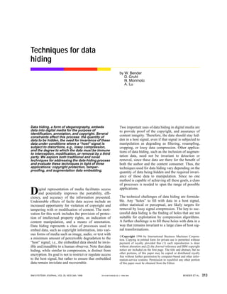
  • 21. IBM SYSTEMS JOURNAL, VOL 35, NOS 3&4, 1996 BENDER ET AL. 333 notice of slight modifications to white space. We describe three methods of using white space to encode data. The methods exploit inter-sentence spacing, end-of-line spaces, and inter-word spacing in justified text. The first method encodes a binary message into a text by placing either one or two spaces after each termi- nating character, e.g., a period for English prose, a semicolon for C-code, etc. A single space encodes a “0,” while two spaces encode a “1.” This method has a number of inherent problems. It is inefficient, requir- ing a great deal of text to encode a very few bits. (One bit per sentence equates to a data rate of approxi- mately one bit per 160 bytes assuming sentences are on average two 80-character lines of text.) Its ability to encode depends on the structure of the text. (Some text, such as free-verse poetry, lacks consistent or well-defined termination characters.) Many word pro- cessors automatically set the number of spaces after periods to one or two characters. Finally, inconsistent use of white space is not transparent. A second method of exploiting white space to encode data is to insert spaces at the end of lines. The data are encoded allowing for a predetermined number of spaces at the end of each line (see Figure 29). Two spaces encode one bit per line, four encode two, eight encode three, etc., dramatically increasing the amount of information we can encode over the previous method. In Figure 29, the text has been selectively justified, and has then had spaces added to the end of lines to encode more data. Rules have been added to reveal the white space at the end of lines. Additional advantages of this method are that it can be done with any text, and it will go unnoticed by readers, since this additional white space is peripheral to the text. As with the previous method, some programs, e.g., “sendmail,” may inadvertently remove the extra space characters. A problem unique to this method is that the hidden data cannot be retrieved from hard copy. A third method of using white space to encode data involves right-justification of text. Data are encoded by controlling where the extra spaces are placed. One space between words is interpreted as a “0.” Two spaces are interpreted as a “1.” This method results in several bits encoded on each line (see Figure 30). Because of constraints upon justification, not every inter-word space can be used as data. In order to determine which of the inter-word spaces represent hidden data bits and which are part of the original text, we have employed a Manchester-like encoding method. Manchester encoding groups bits in sets of two, interpreting “01” as a “1” and “10” as a “0.” The bit strings “00” and “11” are null. For example, the encoded message “1000101101” is reduced to “001,” while “110011” is a null string. Open space methods are useful as long as the text remains in an ASCII (American Standard Character Interchange) format. As mentioned above, some data may be lost when the text is printed. Printed docu- ments present opportunities for data hiding far beyond the capability of an ASCII text file. Data hiding in hard copy is accomplished by making slight variations in word and letter spacing, changes to the baseline posi- tion of letters or punctuation, changes to the letter forms themselves, etc. Also, image data-hiding tech- niques such as those used by Patchwork can be modi- fied to work with printed text. Syntactic methods. That white space is considered arbitrary is both its strength and its weakness where data hiding is concerned. While the reader may not notice its manipulation, a word processor may inad- vertently change the number of spaces, destroying the hidden data. Robustness, in light of document refor- matting, is one reason to look for other methods of data hiding in text. In addition, the use of syntactic and semantic methods generally does not interfere with the open space methods. These methods can be applied in parallel. Figure 29 Example of data hidden using white space T h e q u i c k b r o w n f o x j u m p s o v e r t h e l a z y d o g . T h e q u i c k b r o w n f o x j u m p s o v e r t h e l a z y d o g . NORMAL TEXT WHITE SPACE ENCODED TEXT T h e q u i c k b r o w n f o x j u m p s o v e r t h e l a z y d o g . T h e q u i c k b r o w n f o x j u m p s o v e r t h e l a z y d o g .
  • 22. BENDER ET AL. IBM SYSTEMS JOURNAL, VOL 35, NOS 3&4, 1996334 There are many circumstances where punctuation is ambiguous or when mispunctuation has low impact on the meaning of the text. For example, the phrases “bread, butter, and milk” and “bread, butter and milk” are both considered correct usage of commas in a list. We can exploit the fact that the choice of form is arbi- trary. Alternation between forms can represent binary data, e.g., anytime the first phrase structure (charac- terized by a comma appearing before the “and”) occurs, a “1” is inferred, and anytime the second phrase structure is found, a “0” is inferred. Other examples include the controlled use of contractions and abbreviations. While written English affords numerous cases for the application of syntactic data hiding, these situations occur infrequently in typical prose. The expected data rate of these methods is on the order of only several bits per kilobyte of text. Although many of the rules of punctuation are ambig- uous or redundant, inconsistent use of punctuation is noticeable to even casual readers. Finally, there are cases where changing the punctuation will impact the clarity, or even meaning, of the text considerably. This method should be used with caution. Syntactic methods include changing the diction and structure of text without significantly altering mean- ing or tone. For example, the sentence “Before the night is over, I will have finished” could be stated “I will have finished before the night is over.” These methods are more transparent than the punctuation methods, but the opportunity to exploit them is lim- ited. Semantic methods. A final category of data hiding in text involves changing the words themselves. Seman- tic methods are similar to the syntactic method. Rather than encoding binary data by exploiting ambi- guity of form, these methods assign two synonyms primary or secondary value. For example, the word “big” could be considered primary and “large” sec- ondary. Whether a word has primary or secondary value bears no relevance to how often it will be used, but, when decoding, primary words will be read as ones, secondary words as zeros (see Table 3). Word webs such as WordNet can be used to automati- cally generate synonym tables. Where there are many synonyms, more than one bit can be encoded per sub- stitution. (The choice between “propensity,” “predi- lection,” “penchant,” and “proclivity” represents two bits of data.) Problems occur when the nuances of meaning interfere with the desire to encode data. For example, there is a problem with choice of the syn- onym pair “cool” and “chilly.” Calling someone “cool” has very different connotations than calling them “chilly.” The sentence “The students in line for registration are spaced-out” is also ambiguous. Applications Data hidden in text has a variety of applications, including copyright verification, authentication, and annotation. Making copyright information inseparable Figure 30 Data hidden through justification (text from A Connecticut Yankee in King Arthur’s Court by Mark Twain) 01→0 10→1 This distressed the monks and terrified them. They were not used to hearing these awful beings called names, and they did not know what might be the consequence. There was a dead silence now; superstitious bodings were in every mind. The magician began to pull his wits together, and when he presently smiled an easy, nonchalant smile, it spread a mighty relief around; for it indicated that his mood was not destructive. Table 3 Synonymous pairs ≈ ≈ ≈ ≈ ≈ large little cool clever stretched big small chilly smart spaced
  • 23. IBM SYSTEMS JOURNAL, VOL 35, NOS 3&4, 1996 BENDER ET AL. 335 from the text is one way for publishers to protect their products in an era of increasing electronic distribu- tion. Annotation can be used for tamper protection. For example, if a cryptographic hash of the paper is encoded into the paper, it is a simple matter to deter- mine whether or not the file has been changed. Verifi- cation is among the tasks that could easily be performed by a server which, in this case, would return the judgment “authentic” or “unauthentic” as appropriate. Other uses of data hiding in text involve embedding instructions for an autonomous program in a text. For example, a mail server can be programmed to check for hidden messages when transmitting an electronic message. The message is rejected or approved depending on whether or not any hidden data are found. In this way a company running its own mail server can keep confidential documents from being inadvertently exported. Conclusion In this paper, several techniques are discussed as pos- sible methods for embedding data in host text, image, and audio signals. While we have had some degree of success, all of the proposed methods have limitations. The goal of achieving protection of large amounts of embedded data against intentional attempts at removal may be unobtainable. Automatic detection of geometric and nongeometric modifications applied to the host signal after data hid- ing is a key data-hiding technology. The optimum trade-offs between bit rate, robustness, and perceiv- ability need to be defined experimentally. The interac- tion between various data-hiding technologies needs to be better understood. While compression of image and audio content con- tinues to reduce the necessary bandwidth associated with image and audio content, the need for a better contextual description of that content is increasing. Despite its current shortcomings, data-hiding technol- ogy is important as a carrier of these descriptions. Acknowledgments This work was supported in part by the News in the Future research consortium at the MIT Media Labora- tory and International Business Machines Corpora- tion. Cited references 1. P. Sweene, Error Control Coding (An Introduction), Prentice- Hall International Ltd., Englewood Cliffs, NJ (1991). 2. E. Adelson, Digital Signal Encoding and Decoding Apparatus, U.S. Patent No. 4,939,515 (1990). 3. R. Machado, “Stego,” http://www.nitv.net/~mech/Romana/ stego.html (1994). 4. W. Bender, “Data Hiding,” News in the Future, MIT Media Laboratory, unpublished lecture notes (1994). 5. A. Lippman, Receiver-Compatible Enhanced EDTV System, U.S. Patent No. 5,010,405 (1991). 6. D. L. Hecht, “Embedded Data Glyph Technology for Hardcopy Digital Documents,” SPIE 2171 (1995). 7. K. Matsui and K. Tanaka, “Video-Steganography: How to Secretly Embed a Signature in a Picture,” IMA Intellectual Property Project Proceedings (1994). 8. R. C. Dixon, Spread Spectrum Systems, John Wiley & Sons, Inc., New York (1976). 9. S. K. Marvin, Spread Spectrum Handbook, McGraw-Hill, Inc., New York (1985). 10. Digimarc Corporation, Identification/Authentication Coding Method and Apparatus, U.S. Patent (1995). 11. I. Cox, J. Kilian, T. Leighton, and T. Shamoon, “Secure Spread Spectrum Watermarking for Multimedia,” NECI Technical Report 95-10, NEC Research Institute, Princeton, NJ (1995). 12. A. V. Drake, Fundamentals of Applied Probability, McGraw- Hill, Inc., New York (1967). 13. L. R. Rabiner and R. W. Schaffer, Digital Processing of Speech Signal, Prentice-Hall, Inc., Englewood Cliffs, NJ (1975). 14. A. V. Oppenheim and R. W. Shaffer, Discrete-Time Signal Pro- cessing, Prentice-Hall, Inc., Englewood Cliffs, NJ (1989). Accepted for publication February 29, 1996. Walter Bender MIT Media Laboratory, 20 Ames Street, Cam- bridge, Massachusetts 02139-4307 (electronic mail: walter@ media.mit.edu). Mr. Bender is a principal research scientist at the MIT Media Laboratory and principal investigator of the labora- tory’s News in the Future consortium. He received the B.A. degree from Harvard University in 1977 and joined the Architecture Machine Group at MIT in 1978. He received the M.S. degree from MIT in 1980. Mr. Bender is a founding member of the Media Labo- ratory. Daniel Gruhl MIT Media Laboratory, 20 Ames Street, Cambridge, Massachusetts 02139-4307 (electronic mail: druid@mit.edu). Mr. Gruhl is a doctoral student in the department of electrical engineer- ing and computer science at MIT, where he earned an S.B. in 1994 and an MEng in 1995. He is an AT&T fellow and research assistant at the Media Lab, where his research interests include information hiding in images, sound, and text, as well as user modeling for elec- tronic information systems. Norishige Morimoto IBM Tokyo Research Laboratory, 1623-14 Shimo-Tsuruma, Yamato-shi, Kanagawa-ken, 242 Japan (electronic mail: noly@trl.ibm.co.jp). Mr. Morimoto is currently a researcher at the Tokyo Research Laboratory (TRL) of IBM Japan. He joined IBM in 1987 and was transfered to the TRL in 1995 after getting his master’s degree from MIT. His area of interest is rights manage- ment of digital contents and network applications for industry solu- tions. Mr. Morimoto received his B.S. degree in electrical engineering from Keio University, and his M.S. degree in electrical engineering and computer science from the Massachusetts Institute of Technology.
  • 24. BENDER ET AL. IBM SYSTEMS JOURNAL, VOL 35, NOS 3&4, 1996336 Anthony Lu MIT Media Laboratory, 20 Ames Street, Cambridge, Massachusetts 02139-4307 (electronic mail: tonyl@media.mit. edu). Mr. Lu is an undergraduate student in electrical engineering at MIT, concentrating in communications and signal processing. He will be a candidate for the master of engineering degree in 1997. Reprint Order No. G321-5608.