SlideShare uma empresa Scribd logo
1 de 5
Baixar para ler offline
tection efficiency for the read beam is $ ;
0.04, so we infer the efficiency of quantum
state transfer from the atoms onto the pho-
ton, O ; 0.03.
We have realized a quantum node by
combining the entanglement of atomic and
photonic qubits with the atom-photon quan-
tum state transfer. By implementing the
second node at a different location and
performing a joint detection of the signal
photons from the two nodes, the quantum
repeater protocol (11), as well as distant te-
leportation of an atomic qubit, may be real-
ized. Based on this work, we estimate the
rate for these protocols to be R2 ; ($O"ns)2 R ;
3 Â 10j7sj1. However, improvements in O
that are based on increasing the optical
thickness of atomic samples (16), as well as
elimination of transmission losses, could pro-
vide several orders of magnitude increase in
R2. Our results also demonstrate the possi-
bility of realizing quantum nodes consisting
of multiple atomic qubits by using multiple
beams of light. This approach shows prom-
ise for implementation of distributed quan-
tum computation (20, 21).
References and Notes
1. I. Chuang, M. Nielsen, Quantum Computation and
Quantum Information (Cambridge Univ. Press, Cam-
bridge, 2000).
2. S. Haroche, J. M. Raimond, M. Brune, in Experimental
Quantum Computation and Information, F. de Martini,
C. Monroe, Eds. (Proceedings of the International
School of Physics Enrico Fermi, course CXLVIII, IOS
Press, Amsterdam, 2002), pp. 37–66.
3. C. A. Sackett et al., Nature 404, 256 (2000).
4. M. D. Barrett et al., Nature 429, 737 (2004).
5. M. Riebe et al., Nature 429, 734 (2004).
6. B. B. Blinov, D. L. Moehring, L.-M. Duan, C. Monroe,
Nature 428, 153 (2004).
7. S. Bose, P. L. Knight, M. B. Plenio, V. Vedral, Phys. Rev.
Lett. 83, 5158 (1999).
8. H. J. Kimble, Phys. Scr. 76, 127 (1998).
9. A. Kuzmich, E. S. Polzik, in Quantum Information with
Continuous Variables, S. L. Braunstein, A. K. Pati, Eds.
(Kluwer, Dordrecht, 2003).
10. M. D. Lukin, Rev. Mod. Phys. 75, 457 (2003).
11. L.-M. Duan, M. D. Lukin, I. J. Cirac, P. Zoller, Nature
414, 413 (2001).
12. A. Kuzmich et al., Nature 423, 731 (2003).
13. C. H. van der Wal et al., Science 301, 196 (2003).
14. W. Jiang, C. Han, P. Xue, L.-M. Duan, G. C. Guo, Phys.
Rev. A. 69, 043819 (2004).
15. C. W. Chou, S. V. Polyakov, A. Kuzmich, H. J. Kimble,
Phys. Rev. Lett. 92, 213601 (2004).
16. L.-M. Duan, J. I. Cirac, P. Zoller, Phys. Rev. A. 66,
023818 (2002).
17. A. Kuzmich, T. A. B. Kennedy, Phys. Rev. Lett. 92,
030407 (2004).
18. M. Horodecki, P. Horodecki, R. Horodecki, Phys. Rev.
A. 60, 1888 (1994).
19. C. H. Bennett, D. P. DiVincenzo, J. A. Smolin, W. K.
Wooters, Phys. Rev. A. 54, 3824 (1996).
20. Y. L. Lim, A. Beige, L. C. Kwek, www.arXiv.org/quant-ph/
0408043.
21. S. D. Barrett, P. Kok, www.arXiv.org/quant-ph/0408040.
22. We acknowledge fruitful conversations with T. A. B.
Kennedy, J. A. Sauer, L. You, A. Zangwill and, par-
ticularly, M. S. Chapman and thank R. Smith and E. T.
Neumann for experimental assistance. This work was
supported by NASA and the Research Corporation.
28 July 2004; accepted 16 September 2004
Electric Field Effect in Atomically
Thin Carbon Films
K. S. Novoselov,1
A. K. Geim,1
* S. V. Morozov,2
D. Jiang,1
Y. Zhang,1
S. V. Dubonos,2
I. V. Grigorieva,1
A. A. Firsov2
We describe monocrystalline graphitic films, which are a few atoms thick but are
nonetheless stable under ambient conditions, metallic, and of remarkably high
quality. The films are found to be a two-dimensional semimetal with a tiny overlap
between valence and conductance bands, and they exhibit a strong ambipolar
electric field effect such that electrons and holes in concentrations up to 1013 per
square centimeter and with room-temperature mobilities of È10,000 square
centimeters per volt-second can be induced by applying gate voltage.
The ability to control electronic properties of
a material by externally applied voltage is at
the heart of modern electronics. In many
cases, it is the electric field effect that allows
one to vary the carrier concentration in a
semiconductor device and, consequently,
change an electric current through it. As the
semiconductor industry is nearing the limits
of performance improvements for the current
technologies dominated by silicon, there is a
constant search for new, nontraditional mate-
rials whose properties can be controlled by
the electric field. The most notable recent
examples of such materials are organic
conductors (1) and carbon nanotubes (2). It
has long been tempting to extend the use of
the field effect to metals Ee.g., to develop all-
metallic transistors that could be scaled down
to much smaller sizes and would consume
less energy and operate at higher frequencies
than traditional semiconducting devices (3)^.
However, this would require atomically thin
metal films, because the electric field is
screened at extremely short distances (G1 nm)
and bulk carrier concentrations in metals are
large compared to the surface charge that can
be induced by the field effect. Films so thin
tend to be thermodynamically unstable, be-
coming discontinuous at thicknesses of sev-
eral nanometers; so far, this has proved to be
an insurmountable obstacle to metallic elec-
tronics, and no metal or semimetal has been
shown to exhibit any notable (91%) field ef-
fect (4).
We report the observation of the electric
field effect in a naturally occurring two-
dimensional (2D) material referred to as
few-layer graphene (FLG). Graphene is the
name given to a single layer of carbon atoms
densely packed into a benzene-ring struc-
ture, and is widely used to describe proper-
ties of many carbon-based materials, including
graphite, large fullerenes, nanotubes, etc. (e.g.,
carbon nanotubes are usually thought of as
graphene sheets rolled up into nanometer-sized
cylinders) (5–7). Planar graphene itself has
been presumed not to exist in the free state,
being unstable with respect to the formation of
curved structures such as soot, fullerenes, and
nanotubes (5–14).
Table 1. Conditional probabilities P(IkS) to detect the idler photon in state I given detection of the signal
photon in state S, at the point of maximum correlation for %t 0 100 ns delay between read and write
pulses; all the errors are based on counting statistics of coincidence events.
Basis P(HikHs) P(VikHs) P(VikVs) P(HikVs)
0- 0.92 T 0.02 0.08 T 0.02 0.88 T 0.03 0.12 T 0.03
45- 0.75 T 0.02 0.25 T 0.02 0.81 T 0.02 0.19 T 0.02
0
0.2
0.4
0.6
0.8
1
0 50 100 150
signal-idler delay (ns)
classical threshold
Entanglementfidelity
Fig. 4. Time-dependent entanglement fidelity
of the signal and the idler Fsi; circles for %t 0
100 ns, diamonds for %t 0 200 ns.
1
Department of Physics, University of Manchester,
Manchester M13 9PL, UK. 2
Institute for Microelec-
tronics Technology, 142432 Chernogolovka, Russia.
*To whom correspondence should be addressed.
E-mail: geim@man.ac.uk
R E P O R T S
22 OCTOBER 2004 VOL 306 SCIENCE www.sciencemag.org666
onJune24,2016http://science.sciencemag.org/Downloadedfrom
We have been able to prepare graphitic
sheets of thicknesses down to a few atomic
layers (including single-layer graphene), to
fabricate devices from them, and to study
their electronic properties. Despite being
atomically thin, the films remain of high
quality, so that 2D electronic transport is
ballistic at submicrometer distances. No
other film of similar thickness is known to
be even poorly metallic or continuous under
ambient conditions. Using FLG, we demon-
strate a metallic field-effect transistor in
which the conducting channel can be
switched between 2D electron and hole gases
by changing the gate voltage.
Our graphene films were prepared by
mechanical exfoliation (repeated peeling) of
small mesas of highly oriented pyrolytic
graphite (15). This approach was found to
be highly reliable and allowed us to prepare
FLG films up to 10 6m in size. Thicker films
(d Q 3 nm) were up to 100 6m across and
visible by the naked eye. Figure 1 shows
examples of the prepared films, including
single-layer graphene Esee also (15)^. To
study their electronic properties, we pro-
cessed the films into multiterminal Hall bar
devices placed on top of an oxidized Si
substrate so that a gate voltage Vg could be
applied. We have studied more than 60
devices with d G 10 nm. We focus on the
electronic properties of our thinnest (FLG)
devices, which contained just one, two, or
three atomic layers (15). All FLG devices
exhibited essentially identical electronic
properties characteristic for a 2D semimetal,
which differed from a more complex (2D
plus 3D) behavior observed for thicker,
multilayer graphene (15) as well as from
the properties of 3D graphite.
In FLG, the typical dependence of its sheet
resistivity D on gate voltage Vg (Fig. 2)
exhibits a sharp peak to a value of several
kilohms and decays to È100 ohms at high Vg
(note that 2D resistivity is given in units of
ohms rather than ohms  cm as in the 3D
case). Its conductivity G 0 1/D increases
linearly with Vg on both sides of the resistivity
peak (Fig. 2B). At the same Vg where D has its
peak, the Hall coefficient RH exhibits a sharp
reversal of its sign (Fig. 2C). The observed
behavior resembles the ambipolar field effect
in semiconductors, but there is no zero-
conductance region associated with the Fermi
level being pinned inside the band gap.
Our measurements can be explained
quantitatively by a model of a 2D metal
with a small overlap &( between conductance
and valence bands (15). The gate voltage
induces a surface charge density n 0 (0(Vg/te
and, accordingly, shifts the position of the
Fermi energy (F. Here, (0 and ( are the
permittivities of free space and SiO2, respec-
tively; e is the electron charge; and t is the
thickness of our SiO2 layer (300 nm). For
typical Vg 0 100 V, the formula yields n ,
7.2 Â 1012 cmj2. The electric field doping
transforms the shallow-overlap semimetal
into either completely electron or completely
hole conductor through a mixed state where
both electrons and holes are present (Fig. 2).
The three regions of electric field doping are
clearly seen on both experimental and
theoretical curves. For the regions with only
electrons or holes left, RH decreases with
increasing carrier concentration in the usual
way, as 1/ne. The resistivity also follows the
standard dependence Dj1 0 G 0 ne6 (where
6 is carrier mobility). In the mixed state, G
changes little with Vg, indicating the substi-
tution of one type of carrier with another,
while the Hall coefficient reverses its sign,
reflecting the fact that RH is proportional to
Fig. 1. Graphene films. (A) Photograph (in normal white light) of a relatively large multilayer
graphene flake with thickness È3 nm on top of an oxidized Si wafer. (B) Atomic force microscope
(AFM) image of 2 6m by 2 6m area of this flake near its edge. Colors: dark brown, SiO2 surface;
orange, 3 nm height above the SiO2 surface. (C) AFM image of single-layer graphene. Colors: dark
brown, SiO2 surface; brown-red (central area), 0.8 nm height; yellow-brown (bottom left), 1.2 nm;
orange (top left), 2.5 nm. Notice the folded part of the film near the bottom, which exhibits a
differential height of È0.4 nm. For details of AFM imaging of single-layer graphene, see (15). (D)
Scanning electron microscope image of one of our experimental devices prepared from FLG. (E)
Schematic view of the device in (D).
Fig. 2. Field effect in FLG. (A) Typical
dependences of FLG’s resistivity D on
gate voltage for different temperatures
(T 0 5, 70, and 300 K for top to bottom
curves, respectively). (B) Example of
changes in the film’s conductivity G 0
1/D(Vg) obtained by inverting the 70 K
curve (dots). (C) Hall coefficient RH
versus Vg for the same film; T 0 5 K. (D)
Temperature dependence of carrier
concentration n0 in the mixed state
for the film in (A) (open circles), a
thicker FLG film (squares), and multi-
layer graphene (d , 5 nm; solid circles).
Red curves in (B) to (D) are the
dependences calculated from our mod-
el of a 2D semimetal illustrated by
insets in (C).0
2
4
6
8
-100 -50 0 50 100
0
0.5
-100 0 100
0
3
100 300
2
4
6
D
C
B
ΔF
ρ(k℩)
ΔF
A
ΎΔ
ΔF
RH(k℩T/)
Vg (V)
Vg (V)
σ (m℩
-1
)
T (K)
n0
(T )/ n0
(4K)
0
R E P O R T S
www.sciencemag.org SCIENCE VOL 306 22 OCTOBER 2004 667
onJune24,2016http://science.sciencemag.org/Downloadedfrom
the difference between electron and hole
concentrations.
Without electric field doping (at zero Vg),
FLG was found to be a hole metal, which is
seen as a shift of the peak in D to large
positive Vg. However, this shift is attributed
to an unintentional doping of the films by
absorbed water (16, 17). Indeed, we found
that it was possible to change the position of
the peak by annealing our devices in
vacuum, which usually resulted in shifting
of the peak close to zero voltages. Exposure
of the annealed films to either water vapor or
NH3 led to their p- and n-doping, respec-
tively (15). Therefore, we believe that intrin-
sic FLG is a mixed-carrier material.
Carrier mobilities in FLG were deter-
mined from field-effect and magnetoresist-
ance measurements as 6 0 G(Vg)/en(Vg) and
6 0 RH/D, respectively. In both cases, we
obtained the same values of 6, which varied
from sample to sample between 3000 and
10,000 cm2/VIs. The mobilities were practi-
cally independent of absolute temperature T,
indicating that they were still limited by
scattering on defects. For 6 , 10,000 cm2/VIs
and our typical n , 5 Â 1012 cmj2, the mean
free path is È0.4 6m, which is surprising
given that the 2D gas is at most a few )
away from the interfaces. However, our
findings are in agreement with equally high
6 observed for intercalated graphite (5),
where charged dopants are located next to
graphene sheets. Carbon nanotubes also exhib-
it very high 6, but this is commonly attributed
to the suppression of scattering in the 1D case.
Note that for multilayer graphene, we observed
mobilities up to È15,000 cm2/VIs at 300 K
and È60,000 cm2/VIs at 4 K.
Despite being essentially gigantic fuller-
ene molecules and unprotected from the
environment, FLG films exhibit pronounced
Shubnikov–de Haas (ShdH) oscillations in
both longitudinal resistivity Dxx and Hall re-
sistivity Dxy (Fig. 3A), serving as another
indicator of the quality and homogeneity of
the experimental system. Studies of ShdH os-
cillations confirmed that electronic transport
in FLG was strictly 2D, as one could reason-
ably expect, and allowed us to fully charac-
terize its charge carriers. First, we carried out
the standard test and measured ShdH oscil-
lations for various angles K between the
magnetic field and the graphene films. The
oscillations depended only on the perpendic-
ular component of the magnetic field BIcos K,
as expected for a 2D system. More impor-
tant, however, we found a linear dependence
of ShdH oscillations_ frequencies BF on Vg
(Fig. 3B), indicating that the Fermi energies
(F of holes and electrons were proportional
to their concentrations n. This dependence is
qualitatively different from the 3D dependence
(F Âș n2/3 and proves the 2D nature of charge
carriers in FLG. Further analysis (15) of ShdH
oscillations showed that only a single spa-
tially quantized 2D subband was occupied up
to the maximum concentrations achieved in
our experiments (È3 Â 1013 cmj2). It could
be populated either by electrons with mass
me , 0.06m0 (where m0 is the free electron
mass) located in two equivalent valleys, or
by light and heavy holes with masses of
È0.03m0 and È0.1m0 and the double-valley
degeneracy. These properties were found to
be the same for all FLG films studied and are
notably different from the electronic struc-
ture of both multilayer graphene (15) and
bulk graphite (5–7). Note that graphene is
expected (5–7) to have the linear energy
dispersion and carriers with zero mass, and
the reason why the observed behavior is so
well described by the simplest free-electron
model remains to be understood (15).
We also determined the band overlap &(
in FLG, which varied from 4 to 20 meV for
different samples, presumably indicating a
different number of graphene layers involved
(18). To this end, we first used a peak value
Dm of resistivity to calculate typical carrier
concentrations in the mixed state, n0 (e.g., at
low T for the sample in Fig. 2, A to C, with
6 , 4000 cm2/V and Dm , 8 kilohms, n0 was
È2 Â 1011 cmj2). Then, &( can be estimated
as n0/D, where D 0 2me/>I2 is the 2D
density of electron states and I is Planck_s
constant divided by 2>. For the discussed
sample, this yields &( , 4 meV Ei.e., much
smaller than the overlap in 3D graphite
(È40 meV)^. Alternatively, &( could be
calculated from the temperature dependence
of n0, which characterizes relative contribu-
tions of intrinsic and thermally excited car-
riers. For a 2D semimetal, n0(T) varies as
n0(0 K)IfIlnE1 ĂŸ exp(1/f )^, where f 0 2kBT/&(
and kB is Boltzmann_s constant; Fig. 2D
shows the best fit to this dependence, which
yields &( , 6 meV. Different FLG devices
were found to exhibit a ratio of n0(300 K)/
n0(0) between 2.5 and 7, whereas for
multilayer graphene it was only È1.5 (Fig.
2D). This clearly shows that &( decreases
with decreasing number of graphene layers.
The observed major reduction of &( is in
agreement with the fact that single-layer
graphene is in theory a zero-gap semicon-
ductor (5, 18).
Graphene may be the best possible metal for
metallic transistor applications. In addition to
the scalability to true nanometer sizes envis-
aged for metallic transistors, graphene also
offers ballistic transport, linear current-voltage
(I-V) characteristics, and huge sustainable
currents (9108 A/cm2) (15). Graphene tran-
sistors show a rather modest on-off resistance
ratio (less than È30 at 300 K; limited because
Fig. 3. (A) Examples of ShdH
oscillations for one of our FLG
devices for different gate volt-
ages; T 0 3 K, and B is the mag-
netic field. As the black curve shows,
we often observed pronounced
plateau-like features in Dxy at val-
ues close to (h/4e2)/8 (in this case,
(F matches the Landau level with
filling factor 8 0 2 at around 9 T).
Such not-fully-developed Hall
plateaus are usually viewed as an
early indication of the quantum
Hall effect in the situations where
Dxx does not yet reach the zero-
resistance state. (B) Dependence
of the frequency of ShdH oscilla-
tions BF on gate voltage. Solid and
open symbols are for samples with
&( , 6 meV and 20 meV, respec-
tively. Solid lines are guides to the eye. The linear dependence BF Âș
Vg indicates a constant (2D) density of states (15). The observed
slopes (solid lines) account for the entire external charge n induced
by gate voltage, confirming that there are no other types of carriers
and yielding the double-valley degeneracy for both electrons and
holes (15). The inset shows an example of the temperature
dependence of amplitude % of ShdH oscillations (circles), which is
fitted by the standard dependence T/sinh(2>2kBT/I<c) where <c is
their cyclotron frequency. The fit (solid curve) yields light holes’ mass
of 0.03m0.
2 4 6 8 10
0
0.5
1.0
1.5
1
2
3
4
-100 -50 0 50 100
0
20
40
60
80
50 100
0
10
+80V
-100V
-25V
+100V
ρxx
k(℩)
B (T)
+80V
A
ρyx
k(℩)
BF
)T(
Vg (V)
B
T (K)
∆(℩)
-100V @ 9T
R E P O R T S
22 OCTOBER 2004 VOL 306 SCIENCE www.sciencemag.org668
onJune24,2016http://science.sciencemag.org/Downloadedfrom
of thermally excited carriers), but this is a
fundamental limitation for any material with-
out a band gap exceeding kBT. Nonetheless,
such on-off ratios are considered sufficient for
logic circuits (19), and it is feasible to increase
the ratio further by, for example, using p-n
junctions, local gates (3), or the point contact
geometry. However, by analogy to carbon
nanotubes (2), other, nontransistor applications
of this atomically thin material ultimately may
prove to be the most exciting.
References and Notes
1. C. D. Dimitrakopoulos, D. J. Mascaro, IBM J. Res. Dev.
45, 11 (2001).
2. R. H. Baughman, A. A. Zakhidov, W. A. de Heer,
Science 297, 787 (2002).
3. S. V. Rotkin, K. Hess, Appl. Phys. Lett. 84, 3139
(2004).
4. A. V. Butenko, D. Shvarts, V. Sandomirsky, Y.
Schlesinger, J. Appl. Phys. 88, 2634 (2000).
5. M. S. Dresselhaus, G. Dresselhaus, Adv. Phys. 51, 1
(2002).
6. I. L. Spain, in Chemistry and Physics of Carbon, P. L.
Walker, P. A. Thrower, Eds. (Dekker, New York,
1981), pp. 119–304.
7. O. A. Shenderova, V. V. Zhirnov, D. W. Brenner, Crit.
Rev. Solid State Mater. Sci. 27, 227 (2002).
8. A. Krishnan et al., Nature 388, 451 (1997).
9. E. Dujardin, T. Thio, H. Lezec, T. W. Ebbesen, Appl.
Phys. Lett. 79, 2474 (2001).
10. H. Shioyama, J. Mat. Sci. Lett. 20, 499 (2001).
11. Other methods of preparing thin graphitic layers
exist. The closest analogs of FLG are nanometer-sized
patches of graphene on top of pyrolytic graphite (12,
13), carbon films grown on single-crystal metal
substrates (14), and mesoscopic graphitic disks with
thickness down to È60 graphene layers (8, 9).
12. A. M. Affoune et al., Chem. Phys. Lett. 348, 17
(2001).
13. K. Harigaya, Y. Kobayashi, K. Takai, J. Ravier, T. Enoki,
J. Phys. Cond. Matter 14, L605 (2002).
14. T. A. Land, T. Michely, R. J. Behm, J. C. Hemminger,
G. Comsa, Surf. Sci. 264, 261 (1992).
15. See supporting data on Science Online.
16. J. Kong et al., Science 287, 622 (2000).
17. M. Krušger, I. Widner, T. Nussbaumer, M. Buitelaar,
C. Schošnenberger, N. J. Phys. 5, 138 (2003).
18. We believe that our thinnest FLG samples (as in
Fig. 2A) are in fact zero-gap semiconductors,
because small nonzero values of &( found exper-
imentally can be attributed to inhomogeneous
doping, which smears the zero-gap state over a
small range of Vg and leads to finite apparent &(.
19. M. R. Stan, P. D. Franzon, S. C. Goldstein, J. C. Lach,
M. M. Zeigler, Proc. IEEE 91, 1940 (2003).
20. Supported by the UK Engineering and Physical
Sciences Research Council and the Russian Acad-
emy of Sciences (S.V.M., S.V.D.). We thank L. Eaves,
E. Hill, and O. Shklyarevskii for discussions and
interest.
Supporting Online Material
www.sciencemag.org/cgi/content/full/306/5696/666/
DC1
Materials and Methods
SOM Text
Figs. S1 to S11
References and Notes
19 July 2004; accepted 15 September 2004
Hydrated Electron Dynamics:
From Clusters to Bulk
A. E. Bragg,1
J. R. R. Verlet,1
A. Kammrath,1
O. Cheshnovsky,2
D. M. Neumark1,3
*
The electronic relaxation dynamics of size-selected (H2O)n
–
/(D2O)n
–
[25 e
n e 50] clusters have been studied with time-resolved photoelectron imaging.
The excess electron (ec
–
) was excited through the ec
–
( p) @ ec
–
(s) transition with
an ultrafast laser pulse, with subsequent evolution of the excited state
monitored with photodetachment and photoelectron imaging. All clusters
exhibited p-state population decay with concomitant s-state repopulation
(internal conversion) on time scales ranging from 180 to 130 femtoseconds
for (H2O)n
–
and 400 to 225 femtoseconds for (D2O)n
–
; the lifetimes decrease
with increasing cluster sizes. Our results support the ‘‘nonadiabatic relaxa-
tion’’ mechanism for the bulk hydrated electron (eaq
–
), which invokes a 50-
femtosecond eaq
–
( p) Y eaq
–
(s.) internal conversion lifetime.
A free electron introduced into a polar sol-
vent, such as water (1) or ammonia (2), may
be trapped by locally oriented solvent mole-
cules. In water, an Bequilibrated[ hydrated
electron Eeaq
–
(s)^ can be transiently confined
within a roughly spherical cavity defined by
six OH bonds oriented toward the negative
charge distribution in the so-called Kevan
geometry (3–5). The hydrated electron is an
important reagent in condensed-phase chem-
istry and molecular biology, as it participates
in radiation chemistry, electron transfer, and
charge-induced reactivity. Thus, research in-
vestigating the dynamics of this species,
whether in the presence or absence of other
reagents, has attracted considerable attention
in the theoretical and experimental physical
chemistry communities. Here, we present
time-resolved results on the electronic relax-
ation dynamics of anionic clusters of water
that lend profound insight to the elucidation of
hydrated electron dynamics in the bulk.
The electronic energetics of a hydrated
electron are characterized by three types of
states (Fig. 1A): a localized eaq
–
(s) ground
state; three localized, near-degenerate eaq
–
( p)
excited states; and a delocalized conduction
band (CB) characterized by a charge distri-
bution spread across hundreds of molecules
in the solvent Bnetwork.[ The visible ab-
sorption spectrum of the equilibrium hy-
drated electron, a broad band peaking at
720 nm (1), is well understood as an ex-
citation from the occupied eaq
–
(s) state to the
vacant eaq
–
( p) states (4, 5). The electron-
solvent dynamics subsequent to eaq
– ( p) @
eaq
–
(s) excitation are more controversial, how-
ever, in spite of considerable experimental
(6–12) and theoretical (13, 14) effort devoted
to this problem.
Transient absorption measurements made
with femtosecond (fs) laser pulses as short as 5
fs (12) show a near infrared (NIR) absorption
band beyond 900 nm developing on a 40- to
50-fs time scale after eaq
–
( p) @ eaq
–
(s)
excitation. This broad feature shifts back to
shorter wavelengths on a time scale of several
hundred fs, with recovery of the original eaq
–
(s)
absorption spectrum largely complete within
È1 picosecond (ps). Deuteration of the
solvent (8, 12) appears only to affect the
fastest measured time scale (i.e., the buildup
time of the transient NIR absorption), with
CD2O/CH2O 0 1.4 to 1.6. As described by
Yokoyama et al. (8), two rather different
energy relaxation mechanisms have been
proposed to account for these observations.
In the Badiabatic solvation[ scheme (13, 14),
the infrared transient at the earliest times is
attributed to absorption of the eaq
–
( p) electron,
which is solvated on the upper state within 50
fs (process x in Fig. 1A). The excited electron
then undergoes internal conversion (IC) to the
ground state (y) on a 400-fs time scale,
generating ground-state electrons that further
relax on the È1-ps time scale by dissipating
energy to the solvent. In contrast, the
Bnonadiabatic relaxation[ mechanism (7, 9,
12) invokes much more rapid IC, on a 50-fs
time scale, and attributes the transient NIR
band at early times to absorption of the
ground-state electron in a vibrationally excited
solvent environment. In this model, subsequent
dynamics are assigned to reorganization of the
local (È400 fs) and extended (È1 ps) solvent
network following the electronic decay.
We present an alternative and comple-
mentary approach to assessing the relaxation
dynamics of the hydrated electron through
time-resolved photoelectron imaging (TRPEI)
studies (15) of electron dynamics in size-
selected water cluster anions, (H2O)n
–
and
(D2O)n
–
, with 25 e n e 50. Water cluster
anions were first detected mass spectromet-
1
Department of Chemistry, University of California,
Berkeley, CA 94720, USA. 2
School of Chemistry, The
Sackler Faculty of Exact Sciences, Tel-Aviv University,
69978 Israel. 3
Chemical Sciences Division, Lawrence
Berkeley National Laboratory, Berkeley, CA 94720,
USA.
*To whom correspondence should be addressed.
E-mail: dan@radon.cchem.berkeley.edu
R E P O R T S
www.sciencemag.org SCIENCE VOL 306 22 OCTOBER 2004 669
onJune24,2016http://science.sciencemag.org/Downloadedfrom
(5696), 666-669. [doi: 10.1126/science.1102896]306Science
2004)
S. V. Dubonos, I. V. Grigorieva and A. A. Firsov (October 21,
K. S. Novoselov, A. K. Geim, S. V. Morozov, D. Jiang, Y. Zhang,
Electric Field Effect in Atomically Thin Carbon Films
Editor's Summary
This copy is for your personal, non-commercial use only.
Article Tools
http://science.sciencemag.org/content/306/5696/666
article tools:
Visit the online version of this article to access the personalization and
Permissions
http://www.sciencemag.org/about/permissions.dtl
Obtain information about reproducing this article:
is a registered trademark of AAAS.ScienceAdvancement of Science; all rights reserved. The title
Avenue NW, Washington, DC 20005. Copyright 2016 by the American Association for the
in December, by the American Association for the Advancement of Science, 1200 New York
(print ISSN 0036-8075; online ISSN 1095-9203) is published weekly, except the last weekScience
onJune24,2016http://science.sciencemag.org/Downloadedfrom

Mais conteĂșdo relacionado

Mais procurados

Structural and Optical properties of Multiwalled Carbon Nanotubes Modified by...
Structural and Optical properties of Multiwalled Carbon Nanotubes Modified by...Structural and Optical properties of Multiwalled Carbon Nanotubes Modified by...
Structural and Optical properties of Multiwalled Carbon Nanotubes Modified by...TELKOMNIKA JOURNAL
 
Size effect of nanomaterials part1
Size effect of nanomaterials part1Size effect of nanomaterials part1
Size effect of nanomaterials part1Mugilan Narayanasamy
 
10.1016-j.synthmet.2014.12.031-Graphite nanosheets_nanoporous carbon black_ce...
10.1016-j.synthmet.2014.12.031-Graphite nanosheets_nanoporous carbon black_ce...10.1016-j.synthmet.2014.12.031-Graphite nanosheets_nanoporous carbon black_ce...
10.1016-j.synthmet.2014.12.031-Graphite nanosheets_nanoporous carbon black_ce...Mahdi Robat Sarpoushi
 
How is nano special?
How is nano special?How is nano special?
How is nano special?NANOYOU
 
Bt4301401410
Bt4301401410Bt4301401410
Bt4301401410IJERA Editor
 
eQCM - Electrochemical Quartz Crystal Microbalance
eQCM -  Electrochemical Quartz Crystal MicrobalanceeQCM -  Electrochemical Quartz Crystal Microbalance
eQCM - Electrochemical Quartz Crystal MicrobalanceGamry Instruments
 
Study the effect of Mn2+ ions on the ac electrical properties of some iron do...
Study the effect of Mn2+ ions on the ac electrical properties of some iron do...Study the effect of Mn2+ ions on the ac electrical properties of some iron do...
Study the effect of Mn2+ ions on the ac electrical properties of some iron do...IJRES Journal
 
Electrodeposited pt on three dimensional interconnected graphene as a free st...
Electrodeposited pt on three dimensional interconnected graphene as a free st...Electrodeposited pt on three dimensional interconnected graphene as a free st...
Electrodeposited pt on three dimensional interconnected graphene as a free st...tshankar20134
 
Power Genertaion using Nanofiber
Power Genertaion using NanofiberPower Genertaion using Nanofiber
Power Genertaion using Nanofiberaksh07
 
Non-parabolicity and band gap renormalisation in Si doped ZnO
Non-parabolicity and band gap renormalisation in Si doped ZnONon-parabolicity and band gap renormalisation in Si doped ZnO
Non-parabolicity and band gap renormalisation in Si doped ZnOUniversity of Liverpool
 
Actuating carbon nanotube nanocomposite skins for aerospace applications
Actuating carbon nanotube nanocomposite skins for aerospace applicationsActuating carbon nanotube nanocomposite skins for aerospace applications
Actuating carbon nanotube nanocomposite skins for aerospace applicationsJoe Dolby
 
Studies on in-Doped Zno Transparent Conducting thin Films
Studies on in-Doped Zno Transparent Conducting thin FilmsStudies on in-Doped Zno Transparent Conducting thin Films
Studies on in-Doped Zno Transparent Conducting thin FilmsIJRESJOURNAL
 
Semiconductor nanodevices
Semiconductor nanodevicesSemiconductor nanodevices
Semiconductor nanodevicesAtif Syed
 
Electrical Properties of Thermally Evaporated In40 Se60 Thin Films
Electrical Properties of Thermally Evaporated In40 Se60 Thin FilmsElectrical Properties of Thermally Evaporated In40 Se60 Thin Films
Electrical Properties of Thermally Evaporated In40 Se60 Thin Filmsiosrjce
 
Density of States (DOS) in Nanotechnology by Manu Shreshtha
Density of States (DOS) in Nanotechnology by Manu ShreshthaDensity of States (DOS) in Nanotechnology by Manu Shreshtha
Density of States (DOS) in Nanotechnology by Manu ShreshthaManu Shreshtha
 
Modulus spectroscopy study on Ferroelectric Lithium and Titanium modified Lea...
Modulus spectroscopy study on Ferroelectric Lithium and Titanium modified Lea...Modulus spectroscopy study on Ferroelectric Lithium and Titanium modified Lea...
Modulus spectroscopy study on Ferroelectric Lithium and Titanium modified Lea...iosrjce
 
Nano Tech Lecture2 Dr. A. Waheed Anwar
Nano Tech Lecture2 Dr. A. Waheed AnwarNano Tech Lecture2 Dr. A. Waheed Anwar
Nano Tech Lecture2 Dr. A. Waheed AnwarEngr Mansoor Mirza
 
STUDY OF ABSORPTION IN CARBON NANOTUBE COMPOSITES FROM 1HZ TO 40GHZ
STUDY OF ABSORPTION IN CARBON NANOTUBE COMPOSITES FROM 1HZ TO 40GHZSTUDY OF ABSORPTION IN CARBON NANOTUBE COMPOSITES FROM 1HZ TO 40GHZ
STUDY OF ABSORPTION IN CARBON NANOTUBE COMPOSITES FROM 1HZ TO 40GHZjmicro
 

Mais procurados (20)

Structural and Optical properties of Multiwalled Carbon Nanotubes Modified by...
Structural and Optical properties of Multiwalled Carbon Nanotubes Modified by...Structural and Optical properties of Multiwalled Carbon Nanotubes Modified by...
Structural and Optical properties of Multiwalled Carbon Nanotubes Modified by...
 
Size effect of nanomaterials part1
Size effect of nanomaterials part1Size effect of nanomaterials part1
Size effect of nanomaterials part1
 
10.1016-j.synthmet.2014.12.031-Graphite nanosheets_nanoporous carbon black_ce...
10.1016-j.synthmet.2014.12.031-Graphite nanosheets_nanoporous carbon black_ce...10.1016-j.synthmet.2014.12.031-Graphite nanosheets_nanoporous carbon black_ce...
10.1016-j.synthmet.2014.12.031-Graphite nanosheets_nanoporous carbon black_ce...
 
How is nano special?
How is nano special?How is nano special?
How is nano special?
 
Bt4301401410
Bt4301401410Bt4301401410
Bt4301401410
 
eQCM - Electrochemical Quartz Crystal Microbalance
eQCM -  Electrochemical Quartz Crystal MicrobalanceeQCM -  Electrochemical Quartz Crystal Microbalance
eQCM - Electrochemical Quartz Crystal Microbalance
 
De35589591
De35589591De35589591
De35589591
 
Study the effect of Mn2+ ions on the ac electrical properties of some iron do...
Study the effect of Mn2+ ions on the ac electrical properties of some iron do...Study the effect of Mn2+ ions on the ac electrical properties of some iron do...
Study the effect of Mn2+ ions on the ac electrical properties of some iron do...
 
Electrodeposited pt on three dimensional interconnected graphene as a free st...
Electrodeposited pt on three dimensional interconnected graphene as a free st...Electrodeposited pt on three dimensional interconnected graphene as a free st...
Electrodeposited pt on three dimensional interconnected graphene as a free st...
 
Power Genertaion using Nanofiber
Power Genertaion using NanofiberPower Genertaion using Nanofiber
Power Genertaion using Nanofiber
 
PRB_wellock_1999
PRB_wellock_1999PRB_wellock_1999
PRB_wellock_1999
 
Non-parabolicity and band gap renormalisation in Si doped ZnO
Non-parabolicity and band gap renormalisation in Si doped ZnONon-parabolicity and band gap renormalisation in Si doped ZnO
Non-parabolicity and band gap renormalisation in Si doped ZnO
 
Actuating carbon nanotube nanocomposite skins for aerospace applications
Actuating carbon nanotube nanocomposite skins for aerospace applicationsActuating carbon nanotube nanocomposite skins for aerospace applications
Actuating carbon nanotube nanocomposite skins for aerospace applications
 
Studies on in-Doped Zno Transparent Conducting thin Films
Studies on in-Doped Zno Transparent Conducting thin FilmsStudies on in-Doped Zno Transparent Conducting thin Films
Studies on in-Doped Zno Transparent Conducting thin Films
 
Semiconductor nanodevices
Semiconductor nanodevicesSemiconductor nanodevices
Semiconductor nanodevices
 
Electrical Properties of Thermally Evaporated In40 Se60 Thin Films
Electrical Properties of Thermally Evaporated In40 Se60 Thin FilmsElectrical Properties of Thermally Evaporated In40 Se60 Thin Films
Electrical Properties of Thermally Evaporated In40 Se60 Thin Films
 
Density of States (DOS) in Nanotechnology by Manu Shreshtha
Density of States (DOS) in Nanotechnology by Manu ShreshthaDensity of States (DOS) in Nanotechnology by Manu Shreshtha
Density of States (DOS) in Nanotechnology by Manu Shreshtha
 
Modulus spectroscopy study on Ferroelectric Lithium and Titanium modified Lea...
Modulus spectroscopy study on Ferroelectric Lithium and Titanium modified Lea...Modulus spectroscopy study on Ferroelectric Lithium and Titanium modified Lea...
Modulus spectroscopy study on Ferroelectric Lithium and Titanium modified Lea...
 
Nano Tech Lecture2 Dr. A. Waheed Anwar
Nano Tech Lecture2 Dr. A. Waheed AnwarNano Tech Lecture2 Dr. A. Waheed Anwar
Nano Tech Lecture2 Dr. A. Waheed Anwar
 
STUDY OF ABSORPTION IN CARBON NANOTUBE COMPOSITES FROM 1HZ TO 40GHZ
STUDY OF ABSORPTION IN CARBON NANOTUBE COMPOSITES FROM 1HZ TO 40GHZSTUDY OF ABSORPTION IN CARBON NANOTUBE COMPOSITES FROM 1HZ TO 40GHZ
STUDY OF ABSORPTION IN CARBON NANOTUBE COMPOSITES FROM 1HZ TO 40GHZ
 

Destaque

Prestij Eylul2016
Prestij Eylul2016Prestij Eylul2016
Prestij Eylul2016prestijgroup
 
Spanien - Ibex 35 Index
Spanien - Ibex 35 IndexSpanien - Ibex 35 Index
Spanien - Ibex 35 IndexGapa News
 
Plano de treinos para 4 semanas janeiro
Plano de treinos para 4 semanas janeiroPlano de treinos para 4 semanas janeiro
Plano de treinos para 4 semanas janeirob_martins
 
Medical Records 006.Jpg
Medical Records 006.JpgMedical Records 006.Jpg
Medical Records 006.Jpgfisher_andrea
 
Commemorazione craxi 2012[1]
Commemorazione craxi 2012[1]Commemorazione craxi 2012[1]
Commemorazione craxi 2012[1]Michele Simone
 
Plano de treinos para 4 semanas janeiro
Plano de treinos para 4 semanas janeiroPlano de treinos para 4 semanas janeiro
Plano de treinos para 4 semanas janeirob_martins
 
Self love edited
Self love editedSelf love edited
Self love editedEmily Richard
 
OpiniĂŁo 16 jan 2
OpiniĂŁo 16 jan 2OpiniĂŁo 16 jan 2
OpiniĂŁo 16 jan 2Sergyo Vitro
 
Ajay_Training_Report[1]
Ajay_Training_Report[1]Ajay_Training_Report[1]
Ajay_Training_Report[1]AJAY KUMAR
 
Why MySQL High Availability Matters
Why MySQL High Availability MattersWhy MySQL High Availability Matters
Why MySQL High Availability MattersMark Swarbrick
 
Errezeta zatika
Errezeta zatikaErrezeta zatika
Errezeta zatikaidoialariz
 
Istorioa asmatu1
Istorioa asmatu1Istorioa asmatu1
Istorioa asmatu1MargaGutierrez
 

Destaque (14)

Practica stiven
Practica stivenPractica stiven
Practica stiven
 
Prestij Eylul2016
Prestij Eylul2016Prestij Eylul2016
Prestij Eylul2016
 
Spanien - Ibex 35 Index
Spanien - Ibex 35 IndexSpanien - Ibex 35 Index
Spanien - Ibex 35 Index
 
Plano de treinos para 4 semanas janeiro
Plano de treinos para 4 semanas janeiroPlano de treinos para 4 semanas janeiro
Plano de treinos para 4 semanas janeiro
 
Medical Records 006.Jpg
Medical Records 006.JpgMedical Records 006.Jpg
Medical Records 006.Jpg
 
Commemorazione craxi 2012[1]
Commemorazione craxi 2012[1]Commemorazione craxi 2012[1]
Commemorazione craxi 2012[1]
 
Plano de treinos para 4 semanas janeiro
Plano de treinos para 4 semanas janeiroPlano de treinos para 4 semanas janeiro
Plano de treinos para 4 semanas janeiro
 
Self love edited
Self love editedSelf love edited
Self love edited
 
OpiniĂŁo 16 jan 2
OpiniĂŁo 16 jan 2OpiniĂŁo 16 jan 2
OpiniĂŁo 16 jan 2
 
Ajay_Training_Report[1]
Ajay_Training_Report[1]Ajay_Training_Report[1]
Ajay_Training_Report[1]
 
Why MySQL High Availability Matters
Why MySQL High Availability MattersWhy MySQL High Availability Matters
Why MySQL High Availability Matters
 
Mi mascota tobby
Mi mascota tobbyMi mascota tobby
Mi mascota tobby
 
Errezeta zatika
Errezeta zatikaErrezeta zatika
Errezeta zatika
 
Istorioa asmatu1
Istorioa asmatu1Istorioa asmatu1
Istorioa asmatu1
 

Semelhante a 666.full

Transparent Conducting Oxides for Thin Film PV
Transparent Conducting Oxides for Thin Film PVTransparent Conducting Oxides for Thin Film PV
Transparent Conducting Oxides for Thin Film PVcdtpv
 
Transparent conducting oxides for thin film PV
Transparent conducting oxides for thin film PVTransparent conducting oxides for thin film PV
Transparent conducting oxides for thin film PVUniversity of Liverpool
 
Analysis of Pseudogap in Superconductors
Analysis of Pseudogap in SuperconductorsAnalysis of Pseudogap in Superconductors
Analysis of Pseudogap in SuperconductorsIOSR Journals
 
Graphene plasmonic couple to metallic antenna
Graphene plasmonic couple to metallic antennaGraphene plasmonic couple to metallic antenna
Graphene plasmonic couple to metallic antennaxingangahu
 
Im3314481452
Im3314481452Im3314481452
Im3314481452IJERA Editor
 
JAP-Avril02_SALAHUN
JAP-Avril02_SALAHUNJAP-Avril02_SALAHUN
JAP-Avril02_SALAHUNErwan SALAHUN
 
Sputtering of Ga-doped ZnO nanocoatings on silicon for piezoelectric transducers
Sputtering of Ga-doped ZnO nanocoatings on silicon for piezoelectric transducersSputtering of Ga-doped ZnO nanocoatings on silicon for piezoelectric transducers
Sputtering of Ga-doped ZnO nanocoatings on silicon for piezoelectric transducersMariya Aleksandrova
 
5164 2015 YRen Two-Dimensional Field Effect Transistors
5164 2015 YRen Two-Dimensional Field Effect Transistors5164 2015 YRen Two-Dimensional Field Effect Transistors
5164 2015 YRen Two-Dimensional Field Effect TransistorsYi Ren
 
properties of nanomaterials
properties of nanomaterialsproperties of nanomaterials
properties of nanomaterialsprasad addanki
 
Ik3314371440
Ik3314371440Ik3314371440
Ik3314371440IJERA Editor
 
Temperature Dependence of the Band-Edge Transitions of ZnCdBeSe
Temperature Dependence of the Band-Edge Transitions of ZnCdBeSeTemperature Dependence of the Band-Edge Transitions of ZnCdBeSe
Temperature Dependence of the Band-Edge Transitions of ZnCdBeSeOleg Maksimov
 
Negative resistance contribution of a domain-wall structure in a constricted ...
Negative resistance contribution of a domain-wall structure in a constricted ...Negative resistance contribution of a domain-wall structure in a constricted ...
Negative resistance contribution of a domain-wall structure in a constricted ...Steven Theeuwen
 
11.electronic properties of nanostructured quantum dots
11.electronic properties of nanostructured quantum dots11.electronic properties of nanostructured quantum dots
11.electronic properties of nanostructured quantum dotsAlexander Decker
 
Electronic properties of nanostructured quantum dots
Electronic properties of nanostructured quantum dotsElectronic properties of nanostructured quantum dots
Electronic properties of nanostructured quantum dotsAlexander Decker
 
Final-Investigation into interlayer interactions in MoSe2
Final-Investigation into interlayer interactions in MoSe2Final-Investigation into interlayer interactions in MoSe2
Final-Investigation into interlayer interactions in MoSe2André Mengel
 
H021201058064
H021201058064H021201058064
H021201058064theijes
 
Study of highly broadening Photonic band gaps extension in one-dimensional Me...
Study of highly broadening Photonic band gaps extension in one-dimensional Me...Study of highly broadening Photonic band gaps extension in one-dimensional Me...
Study of highly broadening Photonic band gaps extension in one-dimensional Me...IOSR Journals
 
10.1016-j.mssp.2014.10.034-Graphene nanosheets as electrode materials for sup...
10.1016-j.mssp.2014.10.034-Graphene nanosheets as electrode materials for sup...10.1016-j.mssp.2014.10.034-Graphene nanosheets as electrode materials for sup...
10.1016-j.mssp.2014.10.034-Graphene nanosheets as electrode materials for sup...Mahdi Robat Sarpoushi
 

Semelhante a 666.full (20)

Transparent Conducting Oxides for Thin Film PV
Transparent Conducting Oxides for Thin Film PVTransparent Conducting Oxides for Thin Film PV
Transparent Conducting Oxides for Thin Film PV
 
Transparent conducting oxides for thin film PV
Transparent conducting oxides for thin film PVTransparent conducting oxides for thin film PV
Transparent conducting oxides for thin film PV
 
Analysis of Pseudogap in Superconductors
Analysis of Pseudogap in SuperconductorsAnalysis of Pseudogap in Superconductors
Analysis of Pseudogap in Superconductors
 
Graphene plasmonic couple to metallic antenna
Graphene plasmonic couple to metallic antennaGraphene plasmonic couple to metallic antenna
Graphene plasmonic couple to metallic antenna
 
Scientific_Publication
Scientific_PublicationScientific_Publication
Scientific_Publication
 
1-s2.0-S1369800114000055-main
1-s2.0-S1369800114000055-main1-s2.0-S1369800114000055-main
1-s2.0-S1369800114000055-main
 
Im3314481452
Im3314481452Im3314481452
Im3314481452
 
JAP-Avril02_SALAHUN
JAP-Avril02_SALAHUNJAP-Avril02_SALAHUN
JAP-Avril02_SALAHUN
 
Sputtering of Ga-doped ZnO nanocoatings on silicon for piezoelectric transducers
Sputtering of Ga-doped ZnO nanocoatings on silicon for piezoelectric transducersSputtering of Ga-doped ZnO nanocoatings on silicon for piezoelectric transducers
Sputtering of Ga-doped ZnO nanocoatings on silicon for piezoelectric transducers
 
5164 2015 YRen Two-Dimensional Field Effect Transistors
5164 2015 YRen Two-Dimensional Field Effect Transistors5164 2015 YRen Two-Dimensional Field Effect Transistors
5164 2015 YRen Two-Dimensional Field Effect Transistors
 
properties of nanomaterials
properties of nanomaterialsproperties of nanomaterials
properties of nanomaterials
 
Ik3314371440
Ik3314371440Ik3314371440
Ik3314371440
 
Temperature Dependence of the Band-Edge Transitions of ZnCdBeSe
Temperature Dependence of the Band-Edge Transitions of ZnCdBeSeTemperature Dependence of the Band-Edge Transitions of ZnCdBeSe
Temperature Dependence of the Band-Edge Transitions of ZnCdBeSe
 
Negative resistance contribution of a domain-wall structure in a constricted ...
Negative resistance contribution of a domain-wall structure in a constricted ...Negative resistance contribution of a domain-wall structure in a constricted ...
Negative resistance contribution of a domain-wall structure in a constricted ...
 
11.electronic properties of nanostructured quantum dots
11.electronic properties of nanostructured quantum dots11.electronic properties of nanostructured quantum dots
11.electronic properties of nanostructured quantum dots
 
Electronic properties of nanostructured quantum dots
Electronic properties of nanostructured quantum dotsElectronic properties of nanostructured quantum dots
Electronic properties of nanostructured quantum dots
 
Final-Investigation into interlayer interactions in MoSe2
Final-Investigation into interlayer interactions in MoSe2Final-Investigation into interlayer interactions in MoSe2
Final-Investigation into interlayer interactions in MoSe2
 
H021201058064
H021201058064H021201058064
H021201058064
 
Study of highly broadening Photonic band gaps extension in one-dimensional Me...
Study of highly broadening Photonic band gaps extension in one-dimensional Me...Study of highly broadening Photonic band gaps extension in one-dimensional Me...
Study of highly broadening Photonic band gaps extension in one-dimensional Me...
 
10.1016-j.mssp.2014.10.034-Graphene nanosheets as electrode materials for sup...
10.1016-j.mssp.2014.10.034-Graphene nanosheets as electrode materials for sup...10.1016-j.mssp.2014.10.034-Graphene nanosheets as electrode materials for sup...
10.1016-j.mssp.2014.10.034-Graphene nanosheets as electrode materials for sup...
 

Último

Decoding Kotlin - Your guide to solving the mysterious in Kotlin.pptx
Decoding Kotlin - Your guide to solving the mysterious in Kotlin.pptxDecoding Kotlin - Your guide to solving the mysterious in Kotlin.pptx
Decoding Kotlin - Your guide to solving the mysterious in Kotlin.pptxJoĂŁo Esperancinha
 
Architect Hassan Khalil Portfolio for 2024
Architect Hassan Khalil Portfolio for 2024Architect Hassan Khalil Portfolio for 2024
Architect Hassan Khalil Portfolio for 2024hassan khalil
 
Call Us ≜ 8377877756 ≌ Call Girls In Shastri Nagar (Delhi)
Call Us ≜ 8377877756 ≌ Call Girls In Shastri Nagar (Delhi)Call Us ≜ 8377877756 ≌ Call Girls In Shastri Nagar (Delhi)
Call Us ≜ 8377877756 ≌ Call Girls In Shastri Nagar (Delhi)dollysharma2066
 
TechTACÂź CFD Report Summary: A Comparison of Two Types of Tubing Anchor Catchers
TechTACÂź CFD Report Summary: A Comparison of Two Types of Tubing Anchor CatchersTechTACÂź CFD Report Summary: A Comparison of Two Types of Tubing Anchor Catchers
TechTACÂź CFD Report Summary: A Comparison of Two Types of Tubing Anchor Catcherssdickerson1
 
Concrete Mix Design - IS 10262-2019 - .pptx
Concrete Mix Design - IS 10262-2019 - .pptxConcrete Mix Design - IS 10262-2019 - .pptx
Concrete Mix Design - IS 10262-2019 - .pptxKartikeyaDwivedi3
 
Risk Assessment For Installation of Drainage Pipes.pdf
Risk Assessment For Installation of Drainage Pipes.pdfRisk Assessment For Installation of Drainage Pipes.pdf
Risk Assessment For Installation of Drainage Pipes.pdfROCENODodongVILLACER
 
CCS355 Neural Network & Deep Learning UNIT III notes and Question bank .pdf
CCS355 Neural Network & Deep Learning UNIT III notes and Question bank .pdfCCS355 Neural Network & Deep Learning UNIT III notes and Question bank .pdf
CCS355 Neural Network & Deep Learning UNIT III notes and Question bank .pdfAsst.prof M.Gokilavani
 
Arduino_CSE ece ppt for working and principal of arduino.ppt
Arduino_CSE ece ppt for working and principal of arduino.pptArduino_CSE ece ppt for working and principal of arduino.ppt
Arduino_CSE ece ppt for working and principal of arduino.pptSAURABHKUMAR892774
 
CCS355 Neural Network & Deep Learning Unit II Notes with Question bank .pdf
CCS355 Neural Network & Deep Learning Unit II Notes with Question bank .pdfCCS355 Neural Network & Deep Learning Unit II Notes with Question bank .pdf
CCS355 Neural Network & Deep Learning Unit II Notes with Question bank .pdfAsst.prof M.Gokilavani
 
UNIT III ANALOG ELECTRONICS (BASIC ELECTRONICS)
UNIT III ANALOG ELECTRONICS (BASIC ELECTRONICS)UNIT III ANALOG ELECTRONICS (BASIC ELECTRONICS)
UNIT III ANALOG ELECTRONICS (BASIC ELECTRONICS)Dr SOUNDIRARAJ N
 
Sachpazis Costas: Geotechnical Engineering: A student's Perspective Introduction
Sachpazis Costas: Geotechnical Engineering: A student's Perspective IntroductionSachpazis Costas: Geotechnical Engineering: A student's Perspective Introduction
Sachpazis Costas: Geotechnical Engineering: A student's Perspective IntroductionDr.Costas Sachpazis
 
8251 universal synchronous asynchronous receiver transmitter
8251 universal synchronous asynchronous receiver transmitter8251 universal synchronous asynchronous receiver transmitter
8251 universal synchronous asynchronous receiver transmitterShivangiSharma879191
 
Instrumentation, measurement and control of bio process parameters ( Temperat...
Instrumentation, measurement and control of bio process parameters ( Temperat...Instrumentation, measurement and control of bio process parameters ( Temperat...
Instrumentation, measurement and control of bio process parameters ( Temperat...121011101441
 
Electronically Controlled suspensions system .pdf
Electronically Controlled suspensions system .pdfElectronically Controlled suspensions system .pdf
Electronically Controlled suspensions system .pdfme23b1001
 
CCS355 Neural Networks & Deep Learning Unit 1 PDF notes with Question bank .pdf
CCS355 Neural Networks & Deep Learning Unit 1 PDF notes with Question bank .pdfCCS355 Neural Networks & Deep Learning Unit 1 PDF notes with Question bank .pdf
CCS355 Neural Networks & Deep Learning Unit 1 PDF notes with Question bank .pdfAsst.prof M.Gokilavani
 
INFLUENCE OF NANOSILICA ON THE PROPERTIES OF CONCRETE
INFLUENCE OF NANOSILICA ON THE PROPERTIES OF CONCRETEINFLUENCE OF NANOSILICA ON THE PROPERTIES OF CONCRETE
INFLUENCE OF NANOSILICA ON THE PROPERTIES OF CONCRETEroselinkalist12
 
Correctly Loading Incremental Data at Scale
Correctly Loading Incremental Data at ScaleCorrectly Loading Incremental Data at Scale
Correctly Loading Incremental Data at ScaleAlluxio, Inc.
 

Último (20)

Decoding Kotlin - Your guide to solving the mysterious in Kotlin.pptx
Decoding Kotlin - Your guide to solving the mysterious in Kotlin.pptxDecoding Kotlin - Your guide to solving the mysterious in Kotlin.pptx
Decoding Kotlin - Your guide to solving the mysterious in Kotlin.pptx
 
Architect Hassan Khalil Portfolio for 2024
Architect Hassan Khalil Portfolio for 2024Architect Hassan Khalil Portfolio for 2024
Architect Hassan Khalil Portfolio for 2024
 
young call girls in Rajiv Chowk🔝 9953056974 🔝 Delhi escort Service
young call girls in Rajiv Chowk🔝 9953056974 🔝 Delhi escort Serviceyoung call girls in Rajiv Chowk🔝 9953056974 🔝 Delhi escort Service
young call girls in Rajiv Chowk🔝 9953056974 🔝 Delhi escort Service
 
Call Us ≜ 8377877756 ≌ Call Girls In Shastri Nagar (Delhi)
Call Us ≜ 8377877756 ≌ Call Girls In Shastri Nagar (Delhi)Call Us ≜ 8377877756 ≌ Call Girls In Shastri Nagar (Delhi)
Call Us ≜ 8377877756 ≌ Call Girls In Shastri Nagar (Delhi)
 
POWER SYSTEMS-1 Complete notes examples
POWER SYSTEMS-1 Complete notes  examplesPOWER SYSTEMS-1 Complete notes  examples
POWER SYSTEMS-1 Complete notes examples
 
TechTACÂź CFD Report Summary: A Comparison of Two Types of Tubing Anchor Catchers
TechTACÂź CFD Report Summary: A Comparison of Two Types of Tubing Anchor CatchersTechTACÂź CFD Report Summary: A Comparison of Two Types of Tubing Anchor Catchers
TechTACÂź CFD Report Summary: A Comparison of Two Types of Tubing Anchor Catchers
 
Concrete Mix Design - IS 10262-2019 - .pptx
Concrete Mix Design - IS 10262-2019 - .pptxConcrete Mix Design - IS 10262-2019 - .pptx
Concrete Mix Design - IS 10262-2019 - .pptx
 
Risk Assessment For Installation of Drainage Pipes.pdf
Risk Assessment For Installation of Drainage Pipes.pdfRisk Assessment For Installation of Drainage Pipes.pdf
Risk Assessment For Installation of Drainage Pipes.pdf
 
CCS355 Neural Network & Deep Learning UNIT III notes and Question bank .pdf
CCS355 Neural Network & Deep Learning UNIT III notes and Question bank .pdfCCS355 Neural Network & Deep Learning UNIT III notes and Question bank .pdf
CCS355 Neural Network & Deep Learning UNIT III notes and Question bank .pdf
 
Arduino_CSE ece ppt for working and principal of arduino.ppt
Arduino_CSE ece ppt for working and principal of arduino.pptArduino_CSE ece ppt for working and principal of arduino.ppt
Arduino_CSE ece ppt for working and principal of arduino.ppt
 
young call girls in Green Park🔝 9953056974 🔝 escort Service
young call girls in Green Park🔝 9953056974 🔝 escort Serviceyoung call girls in Green Park🔝 9953056974 🔝 escort Service
young call girls in Green Park🔝 9953056974 🔝 escort Service
 
CCS355 Neural Network & Deep Learning Unit II Notes with Question bank .pdf
CCS355 Neural Network & Deep Learning Unit II Notes with Question bank .pdfCCS355 Neural Network & Deep Learning Unit II Notes with Question bank .pdf
CCS355 Neural Network & Deep Learning Unit II Notes with Question bank .pdf
 
UNIT III ANALOG ELECTRONICS (BASIC ELECTRONICS)
UNIT III ANALOG ELECTRONICS (BASIC ELECTRONICS)UNIT III ANALOG ELECTRONICS (BASIC ELECTRONICS)
UNIT III ANALOG ELECTRONICS (BASIC ELECTRONICS)
 
Sachpazis Costas: Geotechnical Engineering: A student's Perspective Introduction
Sachpazis Costas: Geotechnical Engineering: A student's Perspective IntroductionSachpazis Costas: Geotechnical Engineering: A student's Perspective Introduction
Sachpazis Costas: Geotechnical Engineering: A student's Perspective Introduction
 
8251 universal synchronous asynchronous receiver transmitter
8251 universal synchronous asynchronous receiver transmitter8251 universal synchronous asynchronous receiver transmitter
8251 universal synchronous asynchronous receiver transmitter
 
Instrumentation, measurement and control of bio process parameters ( Temperat...
Instrumentation, measurement and control of bio process parameters ( Temperat...Instrumentation, measurement and control of bio process parameters ( Temperat...
Instrumentation, measurement and control of bio process parameters ( Temperat...
 
Electronically Controlled suspensions system .pdf
Electronically Controlled suspensions system .pdfElectronically Controlled suspensions system .pdf
Electronically Controlled suspensions system .pdf
 
CCS355 Neural Networks & Deep Learning Unit 1 PDF notes with Question bank .pdf
CCS355 Neural Networks & Deep Learning Unit 1 PDF notes with Question bank .pdfCCS355 Neural Networks & Deep Learning Unit 1 PDF notes with Question bank .pdf
CCS355 Neural Networks & Deep Learning Unit 1 PDF notes with Question bank .pdf
 
INFLUENCE OF NANOSILICA ON THE PROPERTIES OF CONCRETE
INFLUENCE OF NANOSILICA ON THE PROPERTIES OF CONCRETEINFLUENCE OF NANOSILICA ON THE PROPERTIES OF CONCRETE
INFLUENCE OF NANOSILICA ON THE PROPERTIES OF CONCRETE
 
Correctly Loading Incremental Data at Scale
Correctly Loading Incremental Data at ScaleCorrectly Loading Incremental Data at Scale
Correctly Loading Incremental Data at Scale
 

666.full

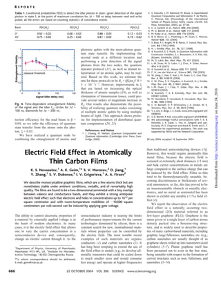
  • 1. tection efficiency for the read beam is $ ; 0.04, so we infer the efficiency of quantum state transfer from the atoms onto the pho- ton, O ; 0.03. We have realized a quantum node by combining the entanglement of atomic and photonic qubits with the atom-photon quan- tum state transfer. By implementing the second node at a different location and performing a joint detection of the signal photons from the two nodes, the quantum repeater protocol (11), as well as distant te- leportation of an atomic qubit, may be real- ized. Based on this work, we estimate the rate for these protocols to be R2 ; ($O"ns)2 R ; 3 Â 10j7sj1. However, improvements in O that are based on increasing the optical thickness of atomic samples (16), as well as elimination of transmission losses, could pro- vide several orders of magnitude increase in R2. Our results also demonstrate the possi- bility of realizing quantum nodes consisting of multiple atomic qubits by using multiple beams of light. This approach shows prom- ise for implementation of distributed quan- tum computation (20, 21). References and Notes 1. I. Chuang, M. Nielsen, Quantum Computation and Quantum Information (Cambridge Univ. Press, Cam- bridge, 2000). 2. S. Haroche, J. M. Raimond, M. Brune, in Experimental Quantum Computation and Information, F. de Martini, C. Monroe, Eds. (Proceedings of the International School of Physics Enrico Fermi, course CXLVIII, IOS Press, Amsterdam, 2002), pp. 37–66. 3. C. A. Sackett et al., Nature 404, 256 (2000). 4. M. D. Barrett et al., Nature 429, 737 (2004). 5. M. Riebe et al., Nature 429, 734 (2004). 6. B. B. Blinov, D. L. Moehring, L.-M. Duan, C. Monroe, Nature 428, 153 (2004). 7. S. Bose, P. L. Knight, M. B. Plenio, V. Vedral, Phys. Rev. Lett. 83, 5158 (1999). 8. H. J. Kimble, Phys. Scr. 76, 127 (1998). 9. A. Kuzmich, E. S. Polzik, in Quantum Information with Continuous Variables, S. L. Braunstein, A. K. Pati, Eds. (Kluwer, Dordrecht, 2003). 10. M. D. Lukin, Rev. Mod. Phys. 75, 457 (2003). 11. L.-M. Duan, M. D. Lukin, I. J. Cirac, P. Zoller, Nature 414, 413 (2001). 12. A. Kuzmich et al., Nature 423, 731 (2003). 13. C. H. van der Wal et al., Science 301, 196 (2003). 14. W. Jiang, C. Han, P. Xue, L.-M. Duan, G. C. Guo, Phys. Rev. A. 69, 043819 (2004). 15. C. W. Chou, S. V. Polyakov, A. Kuzmich, H. J. Kimble, Phys. Rev. Lett. 92, 213601 (2004). 16. L.-M. Duan, J. I. Cirac, P. Zoller, Phys. Rev. A. 66, 023818 (2002). 17. A. Kuzmich, T. A. B. Kennedy, Phys. Rev. Lett. 92, 030407 (2004). 18. M. Horodecki, P. Horodecki, R. Horodecki, Phys. Rev. A. 60, 1888 (1994). 19. C. H. Bennett, D. P. DiVincenzo, J. A. Smolin, W. K. Wooters, Phys. Rev. A. 54, 3824 (1996). 20. Y. L. Lim, A. Beige, L. C. Kwek, www.arXiv.org/quant-ph/ 0408043. 21. S. D. Barrett, P. Kok, www.arXiv.org/quant-ph/0408040. 22. We acknowledge fruitful conversations with T. A. B. Kennedy, J. A. Sauer, L. You, A. Zangwill and, par- ticularly, M. S. Chapman and thank R. Smith and E. T. Neumann for experimental assistance. This work was supported by NASA and the Research Corporation. 28 July 2004; accepted 16 September 2004 Electric Field Effect in Atomically Thin Carbon Films K. S. Novoselov,1 A. K. Geim,1 * S. V. Morozov,2 D. Jiang,1 Y. Zhang,1 S. V. Dubonos,2 I. V. Grigorieva,1 A. A. Firsov2 We describe monocrystalline graphitic films, which are a few atoms thick but are nonetheless stable under ambient conditions, metallic, and of remarkably high quality. The films are found to be a two-dimensional semimetal with a tiny overlap between valence and conductance bands, and they exhibit a strong ambipolar electric field effect such that electrons and holes in concentrations up to 1013 per square centimeter and with room-temperature mobilities of È10,000 square centimeters per volt-second can be induced by applying gate voltage. The ability to control electronic properties of a material by externally applied voltage is at the heart of modern electronics. In many cases, it is the electric field effect that allows one to vary the carrier concentration in a semiconductor device and, consequently, change an electric current through it. As the semiconductor industry is nearing the limits of performance improvements for the current technologies dominated by silicon, there is a constant search for new, nontraditional mate- rials whose properties can be controlled by the electric field. The most notable recent examples of such materials are organic conductors (1) and carbon nanotubes (2). It has long been tempting to extend the use of the field effect to metals Ee.g., to develop all- metallic transistors that could be scaled down to much smaller sizes and would consume less energy and operate at higher frequencies than traditional semiconducting devices (3)^. However, this would require atomically thin metal films, because the electric field is screened at extremely short distances (G1 nm) and bulk carrier concentrations in metals are large compared to the surface charge that can be induced by the field effect. Films so thin tend to be thermodynamically unstable, be- coming discontinuous at thicknesses of sev- eral nanometers; so far, this has proved to be an insurmountable obstacle to metallic elec- tronics, and no metal or semimetal has been shown to exhibit any notable (91%) field ef- fect (4). We report the observation of the electric field effect in a naturally occurring two- dimensional (2D) material referred to as few-layer graphene (FLG). Graphene is the name given to a single layer of carbon atoms densely packed into a benzene-ring struc- ture, and is widely used to describe proper- ties of many carbon-based materials, including graphite, large fullerenes, nanotubes, etc. (e.g., carbon nanotubes are usually thought of as graphene sheets rolled up into nanometer-sized cylinders) (5–7). Planar graphene itself has been presumed not to exist in the free state, being unstable with respect to the formation of curved structures such as soot, fullerenes, and nanotubes (5–14). Table 1. Conditional probabilities P(IkS) to detect the idler photon in state I given detection of the signal photon in state S, at the point of maximum correlation for %t 0 100 ns delay between read and write pulses; all the errors are based on counting statistics of coincidence events. Basis P(HikHs) P(VikHs) P(VikVs) P(HikVs) 0- 0.92 T 0.02 0.08 T 0.02 0.88 T 0.03 0.12 T 0.03 45- 0.75 T 0.02 0.25 T 0.02 0.81 T 0.02 0.19 T 0.02 0 0.2 0.4 0.6 0.8 1 0 50 100 150 signal-idler delay (ns) classical threshold Entanglementfidelity Fig. 4. Time-dependent entanglement fidelity of the signal and the idler Fsi; circles for %t 0 100 ns, diamonds for %t 0 200 ns. 1 Department of Physics, University of Manchester, Manchester M13 9PL, UK. 2 Institute for Microelec- tronics Technology, 142432 Chernogolovka, Russia. *To whom correspondence should be addressed. E-mail: geim@man.ac.uk R E P O R T S 22 OCTOBER 2004 VOL 306 SCIENCE www.sciencemag.org666 onJune24,2016http://science.sciencemag.org/Downloadedfrom
  • 2. We have been able to prepare graphitic sheets of thicknesses down to a few atomic layers (including single-layer graphene), to fabricate devices from them, and to study their electronic properties. Despite being atomically thin, the films remain of high quality, so that 2D electronic transport is ballistic at submicrometer distances. No other film of similar thickness is known to be even poorly metallic or continuous under ambient conditions. Using FLG, we demon- strate a metallic field-effect transistor in which the conducting channel can be switched between 2D electron and hole gases by changing the gate voltage. Our graphene films were prepared by mechanical exfoliation (repeated peeling) of small mesas of highly oriented pyrolytic graphite (15). This approach was found to be highly reliable and allowed us to prepare FLG films up to 10 6m in size. Thicker films (d Q 3 nm) were up to 100 6m across and visible by the naked eye. Figure 1 shows examples of the prepared films, including single-layer graphene Esee also (15)^. To study their electronic properties, we pro- cessed the films into multiterminal Hall bar devices placed on top of an oxidized Si substrate so that a gate voltage Vg could be applied. We have studied more than 60 devices with d G 10 nm. We focus on the electronic properties of our thinnest (FLG) devices, which contained just one, two, or three atomic layers (15). All FLG devices exhibited essentially identical electronic properties characteristic for a 2D semimetal, which differed from a more complex (2D plus 3D) behavior observed for thicker, multilayer graphene (15) as well as from the properties of 3D graphite. In FLG, the typical dependence of its sheet resistivity D on gate voltage Vg (Fig. 2) exhibits a sharp peak to a value of several kilohms and decays to È100 ohms at high Vg (note that 2D resistivity is given in units of ohms rather than ohms  cm as in the 3D case). Its conductivity G 0 1/D increases linearly with Vg on both sides of the resistivity peak (Fig. 2B). At the same Vg where D has its peak, the Hall coefficient RH exhibits a sharp reversal of its sign (Fig. 2C). The observed behavior resembles the ambipolar field effect in semiconductors, but there is no zero- conductance region associated with the Fermi level being pinned inside the band gap. Our measurements can be explained quantitatively by a model of a 2D metal with a small overlap &( between conductance and valence bands (15). The gate voltage induces a surface charge density n 0 (0(Vg/te and, accordingly, shifts the position of the Fermi energy (F. Here, (0 and ( are the permittivities of free space and SiO2, respec- tively; e is the electron charge; and t is the thickness of our SiO2 layer (300 nm). For typical Vg 0 100 V, the formula yields n , 7.2  1012 cmj2. The electric field doping transforms the shallow-overlap semimetal into either completely electron or completely hole conductor through a mixed state where both electrons and holes are present (Fig. 2). The three regions of electric field doping are clearly seen on both experimental and theoretical curves. For the regions with only electrons or holes left, RH decreases with increasing carrier concentration in the usual way, as 1/ne. The resistivity also follows the standard dependence Dj1 0 G 0 ne6 (where 6 is carrier mobility). In the mixed state, G changes little with Vg, indicating the substi- tution of one type of carrier with another, while the Hall coefficient reverses its sign, reflecting the fact that RH is proportional to Fig. 1. Graphene films. (A) Photograph (in normal white light) of a relatively large multilayer graphene flake with thickness È3 nm on top of an oxidized Si wafer. (B) Atomic force microscope (AFM) image of 2 6m by 2 6m area of this flake near its edge. Colors: dark brown, SiO2 surface; orange, 3 nm height above the SiO2 surface. (C) AFM image of single-layer graphene. Colors: dark brown, SiO2 surface; brown-red (central area), 0.8 nm height; yellow-brown (bottom left), 1.2 nm; orange (top left), 2.5 nm. Notice the folded part of the film near the bottom, which exhibits a differential height of È0.4 nm. For details of AFM imaging of single-layer graphene, see (15). (D) Scanning electron microscope image of one of our experimental devices prepared from FLG. (E) Schematic view of the device in (D). Fig. 2. Field effect in FLG. (A) Typical dependences of FLG’s resistivity D on gate voltage for different temperatures (T 0 5, 70, and 300 K for top to bottom curves, respectively). (B) Example of changes in the film’s conductivity G 0 1/D(Vg) obtained by inverting the 70 K curve (dots). (C) Hall coefficient RH versus Vg for the same film; T 0 5 K. (D) Temperature dependence of carrier concentration n0 in the mixed state for the film in (A) (open circles), a thicker FLG film (squares), and multi- layer graphene (d , 5 nm; solid circles). Red curves in (B) to (D) are the dependences calculated from our mod- el of a 2D semimetal illustrated by insets in (C).0 2 4 6 8 -100 -50 0 50 100 0 0.5 -100 0 100 0 3 100 300 2 4 6 D C B ΔF ρ(k℩) ΔF A ΎΔ ΔF RH(k℩T/) Vg (V) Vg (V) σ (m℩ -1 ) T (K) n0 (T )/ n0 (4K) 0 R E P O R T S www.sciencemag.org SCIENCE VOL 306 22 OCTOBER 2004 667 onJune24,2016http://science.sciencemag.org/Downloadedfrom
  • 3. the difference between electron and hole concentrations. Without electric field doping (at zero Vg), FLG was found to be a hole metal, which is seen as a shift of the peak in D to large positive Vg. However, this shift is attributed to an unintentional doping of the films by absorbed water (16, 17). Indeed, we found that it was possible to change the position of the peak by annealing our devices in vacuum, which usually resulted in shifting of the peak close to zero voltages. Exposure of the annealed films to either water vapor or NH3 led to their p- and n-doping, respec- tively (15). Therefore, we believe that intrin- sic FLG is a mixed-carrier material. Carrier mobilities in FLG were deter- mined from field-effect and magnetoresist- ance measurements as 6 0 G(Vg)/en(Vg) and 6 0 RH/D, respectively. In both cases, we obtained the same values of 6, which varied from sample to sample between 3000 and 10,000 cm2/VIs. The mobilities were practi- cally independent of absolute temperature T, indicating that they were still limited by scattering on defects. For 6 , 10,000 cm2/VIs and our typical n , 5 Â 1012 cmj2, the mean free path is È0.4 6m, which is surprising given that the 2D gas is at most a few ) away from the interfaces. However, our findings are in agreement with equally high 6 observed for intercalated graphite (5), where charged dopants are located next to graphene sheets. Carbon nanotubes also exhib- it very high 6, but this is commonly attributed to the suppression of scattering in the 1D case. Note that for multilayer graphene, we observed mobilities up to È15,000 cm2/VIs at 300 K and È60,000 cm2/VIs at 4 K. Despite being essentially gigantic fuller- ene molecules and unprotected from the environment, FLG films exhibit pronounced Shubnikov–de Haas (ShdH) oscillations in both longitudinal resistivity Dxx and Hall re- sistivity Dxy (Fig. 3A), serving as another indicator of the quality and homogeneity of the experimental system. Studies of ShdH os- cillations confirmed that electronic transport in FLG was strictly 2D, as one could reason- ably expect, and allowed us to fully charac- terize its charge carriers. First, we carried out the standard test and measured ShdH oscil- lations for various angles K between the magnetic field and the graphene films. The oscillations depended only on the perpendic- ular component of the magnetic field BIcos K, as expected for a 2D system. More impor- tant, however, we found a linear dependence of ShdH oscillations_ frequencies BF on Vg (Fig. 3B), indicating that the Fermi energies (F of holes and electrons were proportional to their concentrations n. This dependence is qualitatively different from the 3D dependence (F Âș n2/3 and proves the 2D nature of charge carriers in FLG. Further analysis (15) of ShdH oscillations showed that only a single spa- tially quantized 2D subband was occupied up to the maximum concentrations achieved in our experiments (È3 Â 1013 cmj2). It could be populated either by electrons with mass me , 0.06m0 (where m0 is the free electron mass) located in two equivalent valleys, or by light and heavy holes with masses of È0.03m0 and È0.1m0 and the double-valley degeneracy. These properties were found to be the same for all FLG films studied and are notably different from the electronic struc- ture of both multilayer graphene (15) and bulk graphite (5–7). Note that graphene is expected (5–7) to have the linear energy dispersion and carriers with zero mass, and the reason why the observed behavior is so well described by the simplest free-electron model remains to be understood (15). We also determined the band overlap &( in FLG, which varied from 4 to 20 meV for different samples, presumably indicating a different number of graphene layers involved (18). To this end, we first used a peak value Dm of resistivity to calculate typical carrier concentrations in the mixed state, n0 (e.g., at low T for the sample in Fig. 2, A to C, with 6 , 4000 cm2/V and Dm , 8 kilohms, n0 was È2 Â 1011 cmj2). Then, &( can be estimated as n0/D, where D 0 2me/>I2 is the 2D density of electron states and I is Planck_s constant divided by 2>. For the discussed sample, this yields &( , 4 meV Ei.e., much smaller than the overlap in 3D graphite (È40 meV)^. Alternatively, &( could be calculated from the temperature dependence of n0, which characterizes relative contribu- tions of intrinsic and thermally excited car- riers. For a 2D semimetal, n0(T) varies as n0(0 K)IfIlnE1 ĂŸ exp(1/f )^, where f 0 2kBT/&( and kB is Boltzmann_s constant; Fig. 2D shows the best fit to this dependence, which yields &( , 6 meV. Different FLG devices were found to exhibit a ratio of n0(300 K)/ n0(0) between 2.5 and 7, whereas for multilayer graphene it was only È1.5 (Fig. 2D). This clearly shows that &( decreases with decreasing number of graphene layers. The observed major reduction of &( is in agreement with the fact that single-layer graphene is in theory a zero-gap semicon- ductor (5, 18). Graphene may be the best possible metal for metallic transistor applications. In addition to the scalability to true nanometer sizes envis- aged for metallic transistors, graphene also offers ballistic transport, linear current-voltage (I-V) characteristics, and huge sustainable currents (9108 A/cm2) (15). Graphene tran- sistors show a rather modest on-off resistance ratio (less than È30 at 300 K; limited because Fig. 3. (A) Examples of ShdH oscillations for one of our FLG devices for different gate volt- ages; T 0 3 K, and B is the mag- netic field. As the black curve shows, we often observed pronounced plateau-like features in Dxy at val- ues close to (h/4e2)/8 (in this case, (F matches the Landau level with filling factor 8 0 2 at around 9 T). Such not-fully-developed Hall plateaus are usually viewed as an early indication of the quantum Hall effect in the situations where Dxx does not yet reach the zero- resistance state. (B) Dependence of the frequency of ShdH oscilla- tions BF on gate voltage. Solid and open symbols are for samples with &( , 6 meV and 20 meV, respec- tively. Solid lines are guides to the eye. The linear dependence BF Âș Vg indicates a constant (2D) density of states (15). The observed slopes (solid lines) account for the entire external charge n induced by gate voltage, confirming that there are no other types of carriers and yielding the double-valley degeneracy for both electrons and holes (15). The inset shows an example of the temperature dependence of amplitude % of ShdH oscillations (circles), which is fitted by the standard dependence T/sinh(2>2kBT/I<c) where <c is their cyclotron frequency. The fit (solid curve) yields light holes’ mass of 0.03m0. 2 4 6 8 10 0 0.5 1.0 1.5 1 2 3 4 -100 -50 0 50 100 0 20 40 60 80 50 100 0 10 +80V -100V -25V +100V ρxx k(℩) B (T) +80V A ρyx k(℩) BF )T( Vg (V) B T (K) ∆(℩) -100V @ 9T R E P O R T S 22 OCTOBER 2004 VOL 306 SCIENCE www.sciencemag.org668 onJune24,2016http://science.sciencemag.org/Downloadedfrom
  • 4. of thermally excited carriers), but this is a fundamental limitation for any material with- out a band gap exceeding kBT. Nonetheless, such on-off ratios are considered sufficient for logic circuits (19), and it is feasible to increase the ratio further by, for example, using p-n junctions, local gates (3), or the point contact geometry. However, by analogy to carbon nanotubes (2), other, nontransistor applications of this atomically thin material ultimately may prove to be the most exciting. References and Notes 1. C. D. Dimitrakopoulos, D. J. Mascaro, IBM J. Res. Dev. 45, 11 (2001). 2. R. H. Baughman, A. A. Zakhidov, W. A. de Heer, Science 297, 787 (2002). 3. S. V. Rotkin, K. Hess, Appl. Phys. Lett. 84, 3139 (2004). 4. A. V. Butenko, D. Shvarts, V. Sandomirsky, Y. Schlesinger, J. Appl. Phys. 88, 2634 (2000). 5. M. S. Dresselhaus, G. Dresselhaus, Adv. Phys. 51, 1 (2002). 6. I. L. Spain, in Chemistry and Physics of Carbon, P. L. Walker, P. A. Thrower, Eds. (Dekker, New York, 1981), pp. 119–304. 7. O. A. Shenderova, V. V. Zhirnov, D. W. Brenner, Crit. Rev. Solid State Mater. Sci. 27, 227 (2002). 8. A. Krishnan et al., Nature 388, 451 (1997). 9. E. Dujardin, T. Thio, H. Lezec, T. W. Ebbesen, Appl. Phys. Lett. 79, 2474 (2001). 10. H. Shioyama, J. Mat. Sci. Lett. 20, 499 (2001). 11. Other methods of preparing thin graphitic layers exist. The closest analogs of FLG are nanometer-sized patches of graphene on top of pyrolytic graphite (12, 13), carbon films grown on single-crystal metal substrates (14), and mesoscopic graphitic disks with thickness down to È60 graphene layers (8, 9). 12. A. M. Affoune et al., Chem. Phys. Lett. 348, 17 (2001). 13. K. Harigaya, Y. Kobayashi, K. Takai, J. Ravier, T. Enoki, J. Phys. Cond. Matter 14, L605 (2002). 14. T. A. Land, T. Michely, R. J. Behm, J. C. Hemminger, G. Comsa, Surf. Sci. 264, 261 (1992). 15. See supporting data on Science Online. 16. J. Kong et al., Science 287, 622 (2000). 17. M. Krušger, I. Widner, T. Nussbaumer, M. Buitelaar, C. Schošnenberger, N. J. Phys. 5, 138 (2003). 18. We believe that our thinnest FLG samples (as in Fig. 2A) are in fact zero-gap semiconductors, because small nonzero values of &( found exper- imentally can be attributed to inhomogeneous doping, which smears the zero-gap state over a small range of Vg and leads to finite apparent &(. 19. M. R. Stan, P. D. Franzon, S. C. Goldstein, J. C. Lach, M. M. Zeigler, Proc. IEEE 91, 1940 (2003). 20. Supported by the UK Engineering and Physical Sciences Research Council and the Russian Acad- emy of Sciences (S.V.M., S.V.D.). We thank L. Eaves, E. Hill, and O. Shklyarevskii for discussions and interest. Supporting Online Material www.sciencemag.org/cgi/content/full/306/5696/666/ DC1 Materials and Methods SOM Text Figs. S1 to S11 References and Notes 19 July 2004; accepted 15 September 2004 Hydrated Electron Dynamics: From Clusters to Bulk A. E. Bragg,1 J. R. R. Verlet,1 A. Kammrath,1 O. Cheshnovsky,2 D. M. Neumark1,3 * The electronic relaxation dynamics of size-selected (H2O)n – /(D2O)n – [25 e n e 50] clusters have been studied with time-resolved photoelectron imaging. The excess electron (ec – ) was excited through the ec – ( p) @ ec – (s) transition with an ultrafast laser pulse, with subsequent evolution of the excited state monitored with photodetachment and photoelectron imaging. All clusters exhibited p-state population decay with concomitant s-state repopulation (internal conversion) on time scales ranging from 180 to 130 femtoseconds for (H2O)n – and 400 to 225 femtoseconds for (D2O)n – ; the lifetimes decrease with increasing cluster sizes. Our results support the ‘‘nonadiabatic relaxa- tion’’ mechanism for the bulk hydrated electron (eaq – ), which invokes a 50- femtosecond eaq – ( p) Y eaq – (s.) internal conversion lifetime. A free electron introduced into a polar sol- vent, such as water (1) or ammonia (2), may be trapped by locally oriented solvent mole- cules. In water, an Bequilibrated[ hydrated electron Eeaq – (s)^ can be transiently confined within a roughly spherical cavity defined by six OH bonds oriented toward the negative charge distribution in the so-called Kevan geometry (3–5). The hydrated electron is an important reagent in condensed-phase chem- istry and molecular biology, as it participates in radiation chemistry, electron transfer, and charge-induced reactivity. Thus, research in- vestigating the dynamics of this species, whether in the presence or absence of other reagents, has attracted considerable attention in the theoretical and experimental physical chemistry communities. Here, we present time-resolved results on the electronic relax- ation dynamics of anionic clusters of water that lend profound insight to the elucidation of hydrated electron dynamics in the bulk. The electronic energetics of a hydrated electron are characterized by three types of states (Fig. 1A): a localized eaq – (s) ground state; three localized, near-degenerate eaq – ( p) excited states; and a delocalized conduction band (CB) characterized by a charge distri- bution spread across hundreds of molecules in the solvent Bnetwork.[ The visible ab- sorption spectrum of the equilibrium hy- drated electron, a broad band peaking at 720 nm (1), is well understood as an ex- citation from the occupied eaq – (s) state to the vacant eaq – ( p) states (4, 5). The electron- solvent dynamics subsequent to eaq – ( p) @ eaq – (s) excitation are more controversial, how- ever, in spite of considerable experimental (6–12) and theoretical (13, 14) effort devoted to this problem. Transient absorption measurements made with femtosecond (fs) laser pulses as short as 5 fs (12) show a near infrared (NIR) absorption band beyond 900 nm developing on a 40- to 50-fs time scale after eaq – ( p) @ eaq – (s) excitation. This broad feature shifts back to shorter wavelengths on a time scale of several hundred fs, with recovery of the original eaq – (s) absorption spectrum largely complete within È1 picosecond (ps). Deuteration of the solvent (8, 12) appears only to affect the fastest measured time scale (i.e., the buildup time of the transient NIR absorption), with CD2O/CH2O 0 1.4 to 1.6. As described by Yokoyama et al. (8), two rather different energy relaxation mechanisms have been proposed to account for these observations. In the Badiabatic solvation[ scheme (13, 14), the infrared transient at the earliest times is attributed to absorption of the eaq – ( p) electron, which is solvated on the upper state within 50 fs (process x in Fig. 1A). The excited electron then undergoes internal conversion (IC) to the ground state (y) on a 400-fs time scale, generating ground-state electrons that further relax on the È1-ps time scale by dissipating energy to the solvent. In contrast, the Bnonadiabatic relaxation[ mechanism (7, 9, 12) invokes much more rapid IC, on a 50-fs time scale, and attributes the transient NIR band at early times to absorption of the ground-state electron in a vibrationally excited solvent environment. In this model, subsequent dynamics are assigned to reorganization of the local (È400 fs) and extended (È1 ps) solvent network following the electronic decay. We present an alternative and comple- mentary approach to assessing the relaxation dynamics of the hydrated electron through time-resolved photoelectron imaging (TRPEI) studies (15) of electron dynamics in size- selected water cluster anions, (H2O)n – and (D2O)n – , with 25 e n e 50. Water cluster anions were first detected mass spectromet- 1 Department of Chemistry, University of California, Berkeley, CA 94720, USA. 2 School of Chemistry, The Sackler Faculty of Exact Sciences, Tel-Aviv University, 69978 Israel. 3 Chemical Sciences Division, Lawrence Berkeley National Laboratory, Berkeley, CA 94720, USA. *To whom correspondence should be addressed. E-mail: dan@radon.cchem.berkeley.edu R E P O R T S www.sciencemag.org SCIENCE VOL 306 22 OCTOBER 2004 669 onJune24,2016http://science.sciencemag.org/Downloadedfrom
  • 5. (5696), 666-669. [doi: 10.1126/science.1102896]306Science 2004) S. V. Dubonos, I. V. Grigorieva and A. A. Firsov (October 21, K. S. Novoselov, A. K. Geim, S. V. Morozov, D. Jiang, Y. Zhang, Electric Field Effect in Atomically Thin Carbon Films Editor's Summary This copy is for your personal, non-commercial use only. Article Tools http://science.sciencemag.org/content/306/5696/666 article tools: Visit the online version of this article to access the personalization and Permissions http://www.sciencemag.org/about/permissions.dtl Obtain information about reproducing this article: is a registered trademark of AAAS.ScienceAdvancement of Science; all rights reserved. The title Avenue NW, Washington, DC 20005. Copyright 2016 by the American Association for the in December, by the American Association for the Advancement of Science, 1200 New York (print ISSN 0036-8075; online ISSN 1095-9203) is published weekly, except the last weekScience onJune24,2016http://science.sciencemag.org/Downloadedfrom