
Recomendados
Mais conteúdo relacionado
Mais procurados
Mais procurados (20)
Semelhante a Escavadeira hidraulica cat 365 c l
Semelhante a Escavadeira hidraulica cat 365 c l (20)
Mais de 85283081
Mais de 85283081 (14)
Último
Último (20)
Escavadeira hidraulica cat 365 c l
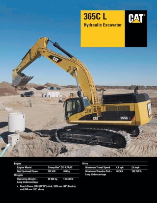
- 1. ®® Engine Engine Model Caterpillar ® C15 ATAAC Net Flywheel Power 302 kW 404 hp Weights Operating Weight – 65 960 kg 145,430 lb Long Undercarriage • Reach Boom, R3.6 (11'10") stick, 1025 mm (40") Bucket, and 650 mm (26") shoes. Drive Maximum Travel Speed 4.1 kph 2.6 mph Maximum Drawbar Pull – 462 kN 103,767 lb Long Undercarriage 365C L Hydraulic Excavator
- 2. 2 365C L Hydraulic Excavator High performance and rugged durability combine to maximize your productivity. High level of sustained production, higher deep trenching and pipe-laying performance, improved reliability and durability increase your productivity and lower your operating costs. Buckets A variety of work tools, including buckets, couplers, hammers, and shears are available through Cat Work Tools. pg. 12 Front Linkage Caterpillar excavator booms and sticks are built for performance and long service life. Two types of booms and six lengths of sticks are available, offering a range of configurations suitable for a wide variety of applications. All booms and sticks are stress relieved. pg. 11 ✔ Operator Station An all-new cab provides improved visibility and comfort. The new monitor is a full-color graphical display with enhanced functionality to provide simple, comprehensive machine interface. pg. 6 ✔ Hydraulics Proportional Priority Pressure Compensated (PPPC) system with state-of-the-art electronic control ensures hydraulic system efficiency and excellent productivity. pg. 5 Engine The Cat ® C15 engine has state-of-the-art ACERT ® technology to meet U.S. EPA Tier 3 emission regulations, with exceptional performance capabilities and proven reliability. pg. 4 ✔
- 3. ✔ New Feature 3 Complete Customer Support Your Cat dealer offers a wide range of services that can be set up under a customer support agreement when you purchase your equipment. The dealer will help you choose a plan that can cover everything from machine configuration to eventual replacement. pg. 14 Service and Maintenance Fast, easy service has been designed in with extended service intervals, advanced filtration, convenient filter access and user-friendly electronic diagnostics for increased productivity and reduced maintenance costs. pg. 13 Structures Caterpillar design and manufacturing techniques assure outstanding durability and service life from these important components. The 365CL uses thicker plates at the boom foot area to improve rigidity. pg. 10 Undercarriage Cat designed excavator undercarriage is stable, durable and low maintenance. The undercarriage is a long, variable gauge type for good machine stability and transportability. pg. 9 ✔ Electronic Control System Engine and machine Electronic Control Modules maximize fuel efficiency and performance by maintaining the optimum balance between engine speed and hydraulic demand. pg. 8
- 4. Diesel Engine. The Caterpillar C15, with ACERT technology, is a 15.2 liter, six-cylinder, 302 kW (404 hp) engine with mechanically actuated electronic fuel injection (MEUI) and overhead camshaft. ACERT technology provides outstanding engine performance through advanced electronic control, precision fuel delivery, and refined air management. Fuel Consumption. The Advanced Diesel Engine Management (A4) controller uses sensors throughout the engine to manage engine load and performance. The A4 controller is the muscle behind engine responsiveness, self-diagnostics, controlling emissions, and fuel economy. Fuel System. C15 engine uses a mechanically actuated electrically controlled unit injection (MEUI) system. The MEUI system combines high- pressure injection and electronic control in a single compact unit. The electronic unit injector is an integral part of the C15 fuel system. Computerized electronic control provides precise metering and timing of fuel injection. Cooling System. High capacity, side-by-side cooling system allows operation in ambient temperatures up to 52 degree C (126 degree F). The Electric Power Control (EPC) controls the fan speed based on coolant temperature and hydraulic oil temperature for optimized cooling. Turbocharger. The C15 engine uses a water-cooled, center-section waste gated turbocharger for improved performance. This turbocharger controls the air volume to the cylinders and works efficiently during low and high load conditions. Emissions. ACERT Technology is a differentiated technology that reduces emissions at the point of combustion. The technology capitalizes on proven Caterpillar leadership in three core engine systems: fuel, air and electronics. Cold Weather Starting Kit. The kit consists of two additional batteries, heavy-duty harness, large capacity starting motor, and the ether starting aid. With this kit, the 365C has the capability to start at –32 degree C (–25.6 degree F). 4 Engine A combination of innovations working at the point of combustion, ACERT technology optimizes engine performance while meeting EPA Tier 3 emission regulations.
- 5. PPPC Hydraulics. Load sensing, Proportional Priority Pressure Compensation (PPPC) system, with Caterpillar-developed electronic actuation, provides high efficiency and excellent controllability. • Cylinder speed is directly related to operator’s movement of joystick from feathering to full speed. • Flow to cylinders during multifunctional operation is directly controlled by the operator and is not dependent on loads. • Controller reduces pump output to minimum to save power when joysticks are in neutral position. Main Pumps. Large, heavy-duty main pumps and a separate swing pump provide quick cycle times during multi-function operation. Reverse Swing Damping Valve. Swing dampening valves reduce swing wag and produce smooth swing stops. Auxiliary Hydraulic Valve. The auxiliary valve is standard on the 365C L. The auxiliary valve is used with optional control arrangements to operate tools such as hammers and shears. 5 Hydraulics Cat hydraulics deliver power and precise control to keep material moving.
- 6. 6 Designed for simple, easy operation and comfort, the 365C L allows the operator to focus on production. Operator Station
- 7. Cab Design. The workstation has been designed to be spacious, quiet and comfortable for the operator, assuring high productivity throughout the entire workday. Switches are conveniently located for easy access. The new monitor is located to provide excellent visibility and access. Seat. The 365C L seat provides a variety of adjustments, including fore/aft, height and weight to suit the operator. Also included are adjustable armrests and a retractable seat belt. For additional comfort, a new heated air suspension seat is available as an attachment. Hydraulic Activation Control Lever. The hydraulic activation control lever deactivates hydraulic functions during engine start-up, and prevents unintentional machine operation. Climate Control. Positive filtered ventilation with a pressurized cab comes standard on the 365C L. Fresh air or re-circulated air can be selected with a switch on the left console. Windows. To maximize visibility, all glass is affixed directly to the cab eliminating the use of window frames. The upper front windshield opens, closes and stores on the roof above the operator with a one-touch action release system. The lower front windshield features a rounded design to maximize downward visibility and improves wiper coverage. Wipers. Pillar-mounted parallelogram wiper, including a washer nozzle, increases the operator’s viewing area and offers continuous and intermittent modes. Skylight. An enlarged skylight with sunshade provides excellent visibility and good ventilation. Monitor. The compact, full-color, graphical display monitor is new with the 365C L. The monitor has functions to display machine, maintenance, diagnostic and prognostic information. The angle of the monitor can be adjusted to face the operator and prevent sun glare. Consoles. Redesigned consoles feature a simple, functional design to reduce operator fatigue, ease of switch operation and excellent visibility. Both consoles have attached armrests and allow the height of the armrests to be adjusted. Cab Exterior. The exterior design uses thick steel tubing along the bottom perimeter of the cab, improving the resistance of fatigue and vibration. This design allows the FOGS to be bolted directly to the cab, at the factory or as an attachment later, enabling the machine to meet specifications and job site requirements. Cab Mounts. The cab shell is attached to the frame with viscous rubber cab mounts, which dampen vibrations and sound levels while enhancing operator comfort. Standard Cab Equipment. To enhance operator comfort and productivity, the 365C L cab includes a lighter, drink holder, coat hook, service meter, literature holder, magazine rack and storage compartment. The cab also comes equipped with two, 12V-7 Amp electrical sockets to provide additional electrical resources. Machine Security. An optional Machine Security System (MSS) is available from the factory on the 365C L. MSS uses a special Caterpillar key with an embedded electronic chip for controlling unauthorized machine operation. Product Link. The 365C L is “Product Link Ready” from the factory. 7
- 8. Monitor Display Screen. The monitor is a full color 400 ן 234 pixels Liquid Crystal Display (LCD) graphic display. The Master Caution Lamp the action lamp blinks ON and OFF when one of the critical conditions below occurs: • Engine oil pressure low • Coolant temperature high • Hydraulic oil temperature high Under normal conditions or the default condition, the monitor display screen is divided into four areas; clock and throttle dial, gage, event display and multi-information display. Clock and Throttle Dial Display. The clock, throttle dial and gas-station icon with green color are displayed in this area. Gage Display. Three analog gauges, fuel level, hydraulic oil temperature and coolant temperature, are displayed in this area. Event Display. Machine event information is displayed in this area along with the icon and language. Multi-information Display. This area is reserved for displaying information that is convenient for the operator. The “CAT” logo mark is displayed when no information is available to display. Operator Gain/Response. This is used to suit the operators preference or application. • Quicker, for fast response and more production • Slower, for more precision • Three preset settings with 21 available Pattern Control Changer. The standard hand control pattern changer can be accessed through the monitor, to utilize either the standard excavator control pattern (SAE) or Backhoe-loader pattern (BHL). Electronic Joysticks. Electronic joysticks provide features not possible with hydraulic pilot valves: • Eliminate pilot lines in cab for quieter operation • Simple pattern change through the monitor 8 Electronic Control System Manages the engine and hydraulics for maximum performance.
- 9. Undercarriage Components. Large, Caterpillar designed and built undercarriage components offer heavy-duty performance and durability. Sealed and Lubricated Rollers. Track rollers, carrier rollers and idlers are sealed and lubricated for excellent service life. Idler Guards and Track Guides. Idler guards and center track guides used to maintain track alignment are standard on the 365C L. Optional two-piece full-length track guiding guards are available for additional protection on steep side slopes. Track. The 365C L comes standard with the new grease lubricated track called GLT4. The track links are assembled and sealed with grease to decrease internal bushing wear, reduce travel noise and extend service life lowering operating costs. Travel Motor. Two-speed axial piston hydraulic motors provide the 365C L drive power and automatic speed selection when the high-speed position is selected. This enables the machine to automatically change between computer-controlled high and low speeds depending on drawbar-pull requirements. Final Drives. The final drives are the three-stage reduction planetary type. This design results in a complete drive/brake unit that is compact and delivers excellent performance and reliability. 9 Undercarriage Durable undercarriage absorbs stresses and provides excellent stability.
- 10. Carbody Design. The advanced carbody design stands up to the toughest applications. • Modified X-shaped, box-section carbody provides excellent resistance to torsional bending. • Upper structure weight and stresses are distributed evenly across the full length of the track roller frame. • Robot welding ensures consistent, high-quality welds throughout the manufacturing process. Upper Frame. Rugged main frame is designed for maximum durability and efficient use of materials. • Robot welding for consistent, high-quality welds. • Outer frame utilizes curved side rails, which are die-formed, for excellent uniformity and strength throughout the length. • Box section channels improve upper frame rigidity under the cab. • Boom tower and one piece main rails are constructed of solid, high-tensile strength steel plates. • New boom foot design transfers load more efficiently with less stress in critical areas. • Reinforced lift cylinder and swing drive mounts increase structure durability in rock and quarry applications. Cross-roller Bearing. The 365C L swing bearing is a cross roller type, with 54 mm (2.13") diameter rollers. The cross rollers have a much greater contact area than ball bearings, providing increased stability and longer life. Track Roller Frames. The track roller frame is made of thick steel plate that is bent into a U-shape and welded to the bottom plate to create a box structure. The box structure design provides increased rigidity and impact resistance. Variable Gauge Undercarriage. The long variable gauge undercarriage is standard, providing a wide, stable base for operating, or a narrow gauge for reduced shipping width. The track roller frames are bolted to the carbody, and can be placed in two positions. 10 Structures The 365C L structural components are the backbone of the machine’s durability.
- 11. Front Linkage Attachments. Select the right combination of front linkage with your Cat dealer to ensure high productivity from the very start of your job. Two types of booms and six sticks are available, offering a range of configurations suitable for a wide variety of applications. The 365C L offers a large combination of reach and digging forces for optimum versatility. Boom Construction. The 365C L booms have large cross-sections and internal baffle plates to provide long life durability. Castings and forgings are used in critical high-load areas such as the boom nose, boom foot, and boom cylinder connection. Reach Boom. The 7.8m (25ft 7in) Reach Boom (R), has been designed to balance the reach, digging force and bucket capacity required for a wide range of applications. Four reach sticks are available for use with the Reach boom. Mass Excavation Boom. The Mass Excavation Boom (M) 6.59m (21ft 7in) is designed to provide maximum productivity. Two Mass sticks are available for high digging forces and increased bucket capacity. Stick Construction. The 365C L sticks are made of high-tensile strength steel using a large box section design with interior baffle plates and an additional bottom guard to protect against damage. All sticks undergo a stress relieving process for greater durability. Reach Sticks. Four lengths of reach sticks are available to suite a variety of applications. Reach sticks use the VB-family bucket linkage and buckets. Mass Sticks. Two mass excavation sticks are available for higher digging forces and increased bucket capacity. Mass sticks use WB-family bucket linkage and buckets. Bucket Linkage. Two bucket linkages are available for the 365C L. Both linkages are available with or without a lifting eye on the power link. • The VB bucket linkage is for use with the reach sticks and VB-family buckets. • The WB bucket linkage is for use with the mass sticks and WB-family buckets Power Link. The new 365C L power link improves durability, increases machine-lifting capability in key lifting positions, and is easier to use compared to the previous lift bar design. Linkage Pins. All pins used in 365C L front linkages have thick chrome plating, giving them high wear and corrosion resistance. The large diameter pins smoothly distribute the shear and bending loads to help ensure long pin, boom and stick life. 11 Front Linkage The 365C L is designed for flexibility, high productivity, and efficiency in a variety of applications.
- 12. Service and Performance. Caterpillar buckets increase service life and optimize performance. • High strength and heat treated steel are located in high wear areas. • Dual radius design for increased heel clearance and reduced wear. • VB-family buckets include a lift eye. • A variety of exclusive hydraulic dedicated coupler buckets are also available. General Purpose (GP) and Excavation (E) Buckets. General Purpose (GP) and Excavation (E) buckets are for digging in soft to hard ground with low to moderate abrasive materials. Heavy Duty (HD) and Extreme Excavation (EX) Buckets. Heavy Duty buckets are intended for use in moderate materials like clay or dirt mixed with rock, and feature aggressive design for moderately abrasive applications. Differences from GP buckets are: • Thicker cutting edges, thicker bottom and side wear plates that improve performance in demanding applications. Heavy Duty Rock (HDR) and Rock (R) Buckets. Heavy Duty Rock (HDR) and Rock (R) buckets for digging in fragmented rock, frozen ground, caliche and highly abrasive materials. Differences from HD buckets are: • Additional, thicker wear plates extend beyond side plates for corner and rear dent protection and improved durability. • Larger side plates provide additional dent protection. Ground Engaging Tools. Caterpillar Ground Engaging Tools (GET) include a variety of side cutters, sidebar protectors, and tip options to match operating conditions. Work Tools. Choose from a variety of work tools such as hammers, shears, rotators, grapples or crushers. Ask your Cat dealer for information on attachments or special configurations. 12 Buckets Extensive selection of buckets helps optimize machine performance.
- 13. Service Intervals. Service intervals are extended to reduce maintenance costs. • Engine oil, oil filter and fuel filters at 500 hours Oil Sample and Pressure Ports. Oil sample and pressure ports provide easy checking of machine condition and are standard on every machine. Hydraulic Capsule Filters. The return filters or capsule filters for the hydraulic system are located beside the hydraulic tank. The filter elements are removable without spilling hydraulic oil. Service Points. Service points are centrally located with easy access to facilitate routine maintenance. Pilot Hydraulic System Filter. Pilot hydraulic system filter keeps contaminants from the pilot system and is located in the pump compartment. Remote Greasing Block. A concentrated remote greasing block on the boom delivers grease to hard-to-reach locations. Radial Seal Cleaner. Radial seal main air cleaner with precleaner has a double-layered filter element for more efficient filtration. No tools are required to change the element. Fuel-Water Separator. The water separator removes water from fuel, even when under pressure, and water level can be monitored in the cab. 13 Service and Maintenance Fast, easy service has been designed in with extended service intervals, advanced filtration, convenient filter access and user-friendly electronic diagnostics for increased productivity and reduced maintenance costs.
- 14. Product Support. You will find nearly all parts at our dealer parts counter. Cat dealers utilize a worldwide computer network to find in-stock parts to minimize machine downtime. You can save money with Cat remanufactured components. Machine Selection. Make detailed comparisons of the machines you are considering before you buy. What are the job requirements, machine attachments and operating hours? What production is needed? Your Cat dealer can provide recommendations. Purchase. Look past initial price. Consider the financing options available as well as day-to-day operating costs. This is also the time to look at dealer services that can be included in the cost of the machine to yield lower equipment owning and operating costs over the long run. Customer Support Agreements. Cat dealers offer a variety of product support agreements, and work with customers to develop a plan the best meets specific needs. These plans can cover the entire machine, including attachments, to help protect the customer’s investment. Operation. Improving operating techniques can boost your profits. Your cat dealer has videotapes, literature and other ideas to help you increase productivity, and Caterpillar offers certified operator training classes to help maximize the return on your investment. Maintenance Services. Repair option programs guarantee the cost of repairs up front. Diagnostic programs such as Scheduled Oil Sampling, Coolant Sampling and Technical Analysis help you avoid unscheduled repairs. Replacement. Repair, rebuild or replace? Your Cat dealer can help you evaluate the cost involved so you can make the right choice. SAFETY.CAT.COM™. 14 Complete Customer Support Cat dealer services help you operate longer with lower costs.
- 15. 15365C L Hydraulic Excavator specifications Drive Maximum Travel Speed 4.1 kph 2.6 mph Maximum Drawbar Pull – 462 kN 103,767 lb Long Undercarriage Hydraulic System Main System – Maximum Flow 800 L/min 212 gal/min (Total) Swing System – Maximum Flow 357 L/min 94 gal/min Maximum Pressure – 32 000 kPa 4,640 psi Equipment – Normal Maximum Pressure – 35 000 kPa 5,080 psi Equipment – Heavy Lift Maximum Pressure – Travel 35 000 kPa 5,080 psi Maximum Pressure – Swing 28 000 kPa 4,060 psi Pilot System – Maximum Flow 90 L/min 24 gal/min Pilot System – Maximum Pressure 4120 kPa 600 psi Boom Cylinder – Bore 190 mm 7.5 in Boom Cylinder – Stroke 1792 mm 70.6 in Stick Cylinder – Bore 200 mm 7.9 in Stick Cylinder – Stroke 2118 mm 83.4 in VB Family Bucket Cylinder – 180 mm 7.1 in Bore VB Family Bucket Cylinder – 1443 mm 56.8 in Stroke WB Family Bucket Cylinder – 200 mm 7.9 in Bore WB Family Bucket Cylinder – 1457 mm 57.4 in Stroke Service Refill Capacities Fuel Tank Capacity 800 L 211 gal Cooling System 95 L 25 gal Engine Oil 54 L 14.3 gal Swing Drive (each) 12 L 3.2 gal Final Drive (each) 15 L 4 gal Hydraulic System 670 L 177 gal (including tank) Hydraulic Tank 310 L 82 gal Engine Engine Model Caterpillar C15 ATAAC Net Flywheel Power 302 kW 404 hp ISO 9249 302 kW 404 hp SAE J1349 302 kW 404 hp EEC 80/1269 302 kW 404 hp Bore 137 mm 5.4 in Stroke 171 mm 6.75 in Displacement 15.2 L 928 in 3 • The 365C L meets worldwide Tier 3 emission requirements. • Net power advertised is the power available at the flywheel when the engine is equipped with fan, air cleaner, muffler and alternator. • No engine power derating required below 2300 m (7,500 ft) altitude. Weights Operating Weight – 65 960 kg 145,430 lb Long Undercarriage • Reach Boom, R3.6 (11'10") stick, 1025 mm (40") Bucket, and 650 mm (26") shoes. Operating Specifications Max Reach at Ground Level 14 m 45.93 ft Max Digging Depth 9.5 m 31.17 ft Track Standard w/Long Undercarriage 900 mm 36 in Optional for Long 750 mm 30 in Undercarriage Optional for Long 650 mm 26 in Undercarriage Number of Shoes Each Side – 47 Long Undercarriage Number of Track Rollers 8 Each Side – Long Undercarriage Number of Carrier Rollers 3 Each Side Swing Mechanism Swing Speed 6.5 RPM Swing Torque 204.5 kN·m 150,850 lb ft
- 16. 16 365C L Hydraulic Excavator specifications Standards Brakes SAE J1026 APR90 Cab/FOGS SAE J1356 FEB88 ISO10262 Sound Performance Performance ANSI/SAE J1166 OCT98 • When properly installed and maintained, the cab offered by Caterpillar, when tested with doors and windows closed according to ANSI/SAE J1166 OCT98, meets OSHA and MSHA requirements for operator sound exposure limits in effect at time of manufacture. • Hearing protection may be needed when operating with an open operator station and cab (when not properly maintained or doors/windows open) for extended periods or in a noisy environment.
- 17. 17365C L Hydraulic Excavator specifications Dimensions All dimensions are approximate. Reach Boom Mass Boom 7.8 m (25'7") 6.59 m (21'7") Stick R4.67 m R4.15 m R3.6 m R2.84 m M3.0 m M2.57 m (15'4") (13'7") (11'10") (9'4") (9'10") (8'5") 1 Shipping Height 4960 mm 4615 mm 4390 mm 4200 mm 4560 mm 4600 mm (16'3") (15'2") (14'5") (13'9") (15'0") (15'1") 2 Shipping Length 13 170 mm 13 225 mm 13 310 mm 13 310 mm 12 150 mm 12 160 mm (43'3") (43'5") (43'9") (43'9") (39'11") (39'11") 3 Tail Swing Radius 4020 mm 4020 mm 4020 mm 4020 mm 4020 mm 4020 mm (13'3") (13'3") (13'3") (13'3") (13'3") (13'3") 4 Length to Center of Rollers 4705 mm 4705 mm 4705 mm 4705 mm 4705 mm 4705 mm (15'5") (15'5") (15'5") (15'5") (15'5") (15'5") 5 Track Length 5860 mm 5860 mm 5860 mm 5860 mm 5860 mm 5860 mm (19'3") (19'3") (19'3") (19'3") (19'3") (19'3") 6 Ground Clearance 840 mm 840 mm 840 mm 840 mm 840 mm 840 mm (33") (33") (33") (33") (33") (33") 7 Track Gauge (Shipping)* 2750 mm 2750 mm 2750 mm 2750 mm 2750 mm 2750 mm (9'0") (9'0") (9'0") (9'0") (9'0") (9'0") 8 Transport Width** 3500 mm 3500 mm 3500 mm 3500 mm 3500 mm 3500 mm (11'6") (11'6") (11'6") (11'6") (11'6") (11'6") 9 Cab Height 3535 mm 3535 mm 3535 mm 3535 mm 3535 mm 3535 mm (11'7") (11'7") (11'7") (11'7") (11'7") (11'7") *** Track gauge in extended (working) position: 3250 mm (10'8") *** Transport width shown for 750 mm (30") shoes. Add 150 mm (6") for 900 mm (36") shoes. Subtract 100 mm (4") for 650 mm (26") shoes. 1 4 5 2 3 9 6 8 7
- 18. 18 365C L Hydraulic Excavator specifications Reach Working Ranges Reach (R) boom configuration Mass Working Ranges Mass (M) boom configuration Reach Boom Mass Boom 7.8 m (25'7") 6.59 m (21'7") Stick R4.67VB R4.15VB R3.60VB R2.84VB M3.00WB M2.57WB (15'4") (13'7") (11'10") (9'4") (9'10") (8'5") Bucket HD 2.8 m HD 2.8 m HD 2.8 m HD 2.8 m Ex 4.6 m Ex 4.6 m 3.68 yd 3.68 yd 3.68 yd 3.68 yd 6.00 yd 6.00 yd 1 Maximum Digging Depth 9640 mm 8940 mm 8390 mm 7630 mm 7170 mm 6750 mm (31'0") (29'4") (27'6") (25'0") (23'6") (22'2") 2 Maximum Reach at Ground Level 14 040 mm 13 490 mm 12 980 mm 12 340 mm 11 240 mm 10 840 mm (46'1") (44'3") (42'7") (40'6") (36'11") (35'7") 3 Maximum Loading Height 9190 mm 8830 mm 8600 mm 8440 mm 7090 mm 6920 mm (30'2") (29'0") (28'3") (27'8") (23'3") (22'8") 4 Minimum Loading Height 2420 mm 2940 mm 3490 mm 4250 mm 2910 mm 3330 mm (7'11") (9'8") (11'5") (13'11") (9'7") (10'11") 5 Maximum Depth Cut for 2240 mm (8') Level Bottom 9350 mm 8820 mm 8260 mm 7480 mm 7020 mm 6580 mm (30'8") (28'11") (27'1") (24'6") (23'0") (21'7") 6 Maximum Vertical Wall Digging Depth 8480 mm 7790 mm 7080 mm 5870 mm 5240 mm 4950 mm (27'10") (25'7") (23'3") (19'3") (17'6") (16'3") Bucket Digging Force (SAE) 256 kN 256 kN 264 kN 277 kN 330 kN 330 kN (59,600 lb) (59,600 lb) (59,300 lb) (62,300 lb) (74,200 lb) (74,200 lb) (ISO) 302 kN 302 kN 301 kN 316 kN 384 kN 383 kN (67,900 lb) (67,900 lb) (67,600 lb) (71,000 lb) (86,300 lb) (86,100 lb) Stick Digging Force (SAE) 193 kN 209 kN 230 kN 257 kN 254 kN 277 kN (43,400 lb) (47,000 lb) (51,700 lb) (57,700 lb) (57,000 lb) (62,200 lb) (ISO) 199 kN 216 kN 239 kN 268 kN 265 kN 290 kN (44,700 lb) (48,600 lb) (53,700 lb) (60,200 lb) (59,500 lb) (65,200 lb) 1 6 5 3 2 4 1 2 3 4 5 6 7 8 9 121315 10 911 8 7 6 5 4 3 2 1 0 -2 -3-1 Meters Feet35 304045 25 20 15 10 5 -50 0 1 2 3 4 5 6 7 8 9 4 5 6 7 8 9 10 11 12 MetersFeet 0 5 10 15 20 25 30 5 10 15 20 25 30 40 13 14 35 45 14 50 16 M2.57WB (8'5") M3.00WB (9'10") 1 6 5 3 2 4 121315 10 911 8 7 6 5 4 3 2 1 0 -2 -3-1 Meters Feet35 304045 25 20 15 10 5 -50 14 50 16 R3.60VB (11'10") R4.67VB (15'4") R4.15VB (13'7") R2.84VB (9'4") s 1 2 3 4 5 6 7 8 9 0 1 2 3 4 5 6 7 8 9 4 5 6 7 8 9 10 11 12 MeterFeet 0 5 10 15 20 25 30 5 10 15 20 25 30 40 13 14 35 45
- 19. 19365C L Hydraulic Excavator specifications Operating Weight* and Ground Pressure Track Configuration 900 mm (36") Shoes 750 mm (30") Shoes 650 mm (26") Shoes Operating Weight Ground Pressure Operating Weight Ground Pressure Operating Weight Ground Pressure kg lb kPa psi kg lb kPa psi kg lb kPa psi 7.8 m (25'7") reach boom 1690 mm (66") HD bucket R4.67 m (15'4") stick 69 250 152,680 73.9 10.71 68 200 150,370 87.3 12.66 67 520 148,870 99.7 14.46 R4.15 m (13'7") stick 69 090 152,330 73.7 10.69 68 040 150,020 87.1 12.63 67 360 148,520 99.5 14.43 R3.60 m (11'10") stick 68 880 151,850 73.5 10.66 67 830 149,540 86.8 12.59 67 150 148,040 99.2 14.38 R2.84 m (9'4") stick 68 670 151,400 73.2 10.62 67 620 149,090 86.5 12.55 66 940 147,590 98.9 14.34 6.59 m (21'7") mass boom 2200 mm (87") X bucket M3.00 m (9'10") stick 70 870 156,240 75.6 10.96 69 820 153,930 89.4 12.96 69 140 152,430 102.1 14.81 M2.57 m (8'5") stick 70 920 156,360 75.6 10.97 69 870 154,050 89.4 12.97 69 190 152,550 102.2 14.82 * Operating weight includes full fuel tank and 75 kg (165 lb) operator Major Component Weights kg lb Base machine with counterweight and 900 mm (36") shoes (without front linkage) 54 890 121,000 Two boom cylinders 1335 2900 Counterweight Removal type 9300 20,500 Non-removal type 10 050 22,200 Boom (includes lines, pins and stick cylinder) Reach boom 7.8 m (25'7") 6400 14,100 Mass boom 6.59 m (21'7") 6420 14,200 Stick (includes lines, pins, bucket cylinder and linkage) R4.67VB (15'4") 3980 8800 R4.15VB (13'7") 3800 8400 R3.6VB (11'10") 3580 7900 R2.84VB (9'4") 3370 7400 M3.0WB (9'10") 4230 9300 M2.57WB (8'5") 4050 8900 Track roller frame [includes frame, rollers, idlers, steps, guards, final drive, 900 mm (36") shoes] – each 10 810 23,800
- 20. 20 365C L Hydraulic Excavator specifications s 2100 kg/m3 (3500 lb/yd3 ) max material density n 1800 kg/m3 (3000 lb/yd3 ) max material density * 1500 kg/m3 (2500 lb/yd3 ) max material density 1200 kg/m3 (2000 lb/yd3 ) max material density n Assumptions for maximum material density rating 1. Front linkage fully extended at ground line 2. Bucket curled 3. 100% bucket fill factor * Capacities based on SAE J296. Some calculations of capacity fall on borderlines. Rounding may allow two buckets to have the same English rating but different metric ratings. 365C L Bucket Specifications and Compatibility Weight Reach Boom Capacity* Width Tip Radius w/o tips Teeth Stick m3 yd3 mm in mm in kg lb Qty R4.67VB R4.15VB R3.6VB R2.84VB VB Buckets General Purpose 1.6 2.12 1025 40 2150 84.6 1912 4210 3 s s s s 2.7 3.61 1545 60 2150 84.6 2447 5390 5 s s s s 3.8 5.00 1905 75 2195 86.4 2849 6280 6 * n s Heavy Duty 1.8 2.42 1225 48 2060 81.1 2088 4600 4 s s s s 2.8 3.68 1690 66 2060 81.1 2591 5710 5 n s s s 3.3 4.30 1905 75 2060 81.1 2866 6310 6 * n s s Heavy Duty Rock 1.5 1.92 1025 40 2060 81.1 1967 4330 3 s s s s 2.5 3.20 1545 60 2060 81.1 2600 5730 5 s s s s 3.3 4.30 1905 75 2060 81.1 3041 6700 6 * n s s Weight Mass Boom Capacity* Width Tip Radius w/o tips Teeth Stick m3 yd3 mm in mm in kg lb Qty M3.0WB M2.57WB WB Buckets Excavation 4.6 6.00 2200 87 2175 85.6 4000 8810 5 n s Extreme Excavation 4.0 5.20 2000 79 2175 85.6 3915 8620 5 s s Rock-V-Edge 4.0 5.20 2000 79 2250 88.6 4420 9740 4 s s n
- 21. 21365C L Hydraulic Excavator specifications Reach Boom Lift Capacities * Limited to hydraulic capacity rather than tipping load. The above loads are in compliance with hydraulic excavator lift capacity rating standard SAE J/ISO 10567. They do not exceed 87% of hydraulic lifting capacity or 75% of tipping capacity. Weight of all lifting accessories must be deducted from the above lifting capacities. 3.0 m/10.0 ft 4.5 m/15.0 ft 6.0 m/20.0 ft 7.5 m/25.0 ft 9.0 m/30.0 ft 10.5 m/35.0 ft 12.0 m/40.0 ft m ft 10.5 m kg *4700 *4700 11.58 35.0 ft lb *10,450 *10,450 37.56 9.0 m kg *7430 *7430 *4430 *4430 12.55 30.0 ft lb *14,400 *14,400 *9800 *9800 40.92 7.5 m kg *8980 *8980 *4340 *4340 13.24 25.0 ft lb *19,200 *19,200 *9600 *9600 43.28 6.0 m kg *11 000 *11 000 *10 210 9120 *6860 6770 *4360 *4360 13.68 20.0 ft lb *23,950 *23,950 *21,900 19,500 *9600 *9600 44.82 4.5 m kg *14 160 *14 160 *12 240 11 810 *10 920 8820 *8600 6650 *4480 *4480 13.92 15.0 ft lb *30,600 *30,600 *26,550 25,350 *23,750 18,900 *17,100 14,150 *9850 *9850 45.64 3.0 m kg *27 990 *27 990 *20 440 *20 440 *16 040 15 290 *13 380 11 220 *11 610 8480 *9870 6470 *4690 *4690 13.96 10.0 ft lb *44,050 *44,050 *34,650 32,900 *29,000 24,100 *25,200 18,150 *19,900 13,800 *10,350 *10,350 45.80 1.5 m kg *15 260 *15 260 *23 080 20 390 *17 680 14 360 *14 420 10 660 *12 230 8130 10 070 6280 *5030 4820 13.81 5.0 ft lb *36,200 *36,200 *49,800 43,900 *38,250 30,900 *31,200 22,900 *26,500 17,400 *21,500 13,400 *11,050 10,600 45.31 Ground kg *14 480 *14 480 *24 620 19 300 *18 810 13 650 *15 150 10 190 12 440 7840 9900 6130 *5510 5010 13.46 Line lb *33,650 *33,650 *53,250 41,500 *40,700 29,350 *32,800 21,900 26,700 16,800 *20,650 13,100 *12,150 11,050 44.15 –1.5 m kg *9010 *9010 *17 960 *17 960 *24 990 18 710 *19 240 13 190 *15 430 9870 12 230 7640 *8530 6050 *6200 5420 12.89 –5.0 ft lb *20,400 *20,400 *41,250 *41,250 *54,100 40,200 *41,600 28,350 *33,350 21,200 26,250 16,400 *13,700 11,950 42.26 –3.0 m kg *14 430 *14 430 *23 850 *23 850 *24 260 18 510 *18 870 12 990 *15 080 9730 *12 120 7580 *7210 6150 12.08 –10.0 ft lb *32,650 *32,650 *54,650 *54,650 *52,500 39,800 *40,800 27,900 *32,500 20,900 *25,950 16,250 *16,000 13,650 39.53 –4.5 m kg *21 110 *21 110 *29 270 *29 270 *22 370 18 630 *17 530 13 020 *13 840 9770 *10 360 7710 *7840 7450 10.96 –15.0 ft lb *47,850 *47,850 *63,250 *63,250 *48,250 40,050 *37,700 28,000 *29,600 21,050 *17,050 16,600 35.74 –6.0 m kg *27 140 *27 140 *24 520 *24 520 *19 020 *19 020 *14 790 13 320 *10 910 10 090 *5400 *5400 9.39 –20.0 ft lb *56,750 *56,750 *52,550 *52,550 *40,650 *40,650 *31,400 28,700 *22,450 21,800 –7.5 m kg *17 170 *17 170 *13 290 *13 290 *9190 *9190 –25.0 ft lb *35,800 *35,800 *27,400 *27,400 ➤ ➤ ➤ ➤ ➤ ➤ ➤ ➤ ➤ ➤ ➤ ➤ ➤ ➤ ➤ ➤ ➤ ➤ ➤ ➤ ➤ ➤ ➤ ➤ ➤ ➤ ➤ ➤ ➤ ➤ ➤ ➤ BOOM – 7.8 m (25'7") STICK – 4670 mm (15'4") BUCKET – 1545 mm (60") GP with HD long tips SHOES – 900 mm (36") double grouser UNDERCARRIAGE – Long HEAVY LIFT – On Load at Maximum Reach Load Point Height Load Radius Over Front Load Radius Over Side * Limited to hydraulic capacity rather than tipping load. The above loads are in compliance with hydraulic excavator lift capacity rating standard SAE J/ISO 10567. They do not exceed 87% of hydraulic lifting capacity or 75% of tipping capacity. Weight of all lifting accessories must be deducted from the above lifting capacities. 3.0 m/10.0 ft 4.5 m/15.0 ft 6.0 m/20.0 ft 7.5 m/25.0 ft 9.0 m/30.0 ft 10.5 m/35.0 ft m ft 10.5 m kg *7990 *7990 *5490 *5490 10.90 35.0 ft lb *12,200 *12,200 35.29 9.0 m kg *10 310 *10 310 *5200 *5200 11.94 30.0 ft lb *22,100 *22,100 *11,500 *11,500 38.90 7.5 m kg *11 150 *11 150 *9410 9150 *5120 *5120 12.66 25.0 ft lb *24,350 *24,350 *18,900 *18,900 *11,300 *11,300 41.39 6.0 m kg *11 910 *11 910 *10 920 9010 *5160 *5160 13.13 20.0 ft lb *25,900 *25,900 *23,750 19,250 *11,350 *11,350 43.01 4.5 m kg *25 130 *25 130 *18 560 *18 560 *15 070 *15 070 *12 910 11 680 *11 470 8750 *5320 *5320 13.38 15.0 ft lb *39,950 *39,950 *32,600 *32,600 *28,000 25,100 *24,950 18,700 *11,700 *11,700 43.87 3.0 m kg *21 620 21 540 *16 840 15 080 *13 980 11 130 *12 080 8440 *5590 5270 13.42 10.0 ft lb *46,600 46,400 *36,400 32,500 *30,250 23,900 *26,200 18,050 *12,300 11,650 44.04 1.5 m kg *13 130 *13 130 *23 920 20 090 *18 310 14 230 *14 890 10 610 *12 590 8130 *6000 5290 13.26 5.0 ft lb *30,400 *30,400 *51,650 43,250 *39,600 30,650 *32,250 22,800 *27,300 17,400 *13,200 11,650 43.53 Ground kg *14 220 *14 220 *25 050 19 170 *19 200 13 600 *15 470 10 200 12 470 7880 *6600 5310 12.90 Line lb *33,000 *33,000 *54,200 41,250 *41,550 29,250 *33,450 21,900 26,800 16,900 *14,550 12,150 42.31 –1.5 m kg *9950 *9950 *19 050 *19 050 *25 000 18 730 *19 370 13 230 *15 550 9940 12 320 7730 *7450 6000 12.30 –5.0 ft lb *22,550 *22,550 *43,750 *43,750 *54,150 40,250 *41,900 28,450 *33,600 21,350 26,450 16,600 *16,450 13,250 40.32 –3.0 m kg *16 350 *16 350 *26 290 *26 290 *23 850 18 660 *18 690 13 110 *14 920 9860 *11 760 7730 *8730 6900 11.44 –10.0 ft lb *36,950 *36,950 *59,500 *59,500 *51,600 40,100 *40,350 28,200 *32,150 21,200 *24,950 16,650 *19,350 15,300 37.42 –4.5 m kg *23 450 *23 450 *27 650 *27 650 *21 510 18 890 *16 940 13 240 *13 210 9990 *6800 *6800 10.23 –15.0 ft lb *52,200 *52,200 *59,750 *59,750 *46,350 40,600 *36,400 28,500 *28,100 21,550 *14,750 *14,750 33.35 –6.0 m kg *26 980 *26 980 *22 220 *22 220 *17 520 *17 520 *13 490 *13 490 –20.0 ft lb *60,650 *60,650 *47,500 *47,500 *37,300 *37,300 *28,350 *28,350 ➤ ➤ ➤ ➤ ➤ ➤ ➤ ➤ ➤ ➤ ➤ ➤ ➤ ➤ ➤ ➤ ➤ ➤ ➤ ➤ ➤ ➤ ➤ ➤ ➤ ➤ ➤ ➤ BOOM – 7.8 m (25'7") STICK – 4150 mm (13'7") BUCKET – 1545 mm (60") GP with HD long tips SHOES – 900 mm (36") double grouser UNDERCARRIAGE – Long HEAVY LIFT – On
- 22. 22 365C L Hydraulic Excavator specifications * Limited to hydraulic capacity rather than tipping load. The above loads are in compliance with hydraulic excavator lift capacity rating standard SAE J/ISO 10567. They do not exceed 87% of hydraulic lifting capacity or 75% of tipping capacity. Weight of all lifting accessories must be deducted from the above lifting capacities. 3.0 m/10.0 ft 4.5 m/15.0 ft 6.0 m/20.0 ft 7.5 m/25.0 ft 9.0 m/30.0 ft 10.5 m/35.0 ft m ft 10.5 m kg *6530 *6530 10.50 35.0 ft lb *14,500 *14,500 33.07 9.0 m kg *10 280 *10 280 *6190 *6190 11.35 30.0 ft lb *22,050 *22,050 *13,700 *13,700 36.95 7.5 m kg *12 000 *12 000 *6100 *6100 12.12 25.0 ft lb *26,200 *26,200 *13,450 *13,450 39.59 6.0 m kg *14 370 *14 370 *12 700 12 040 *11 610 8920 *6150 *6150 12.61 20.0 ft lb *31,100 *31,100 *27,600 25,850 *24,250 19,000 *13,550 *13,550 41.30 4.5 m kg *27 710 *27 710 *19 960 *19 960 *16 010 15 810 *13 630 11 580 *12 060 8700 *6340 5940 12.87 15.0 ft lb *59,250 *59,250 *42,950 *42,950 *34,600 34,050 *29,550 24,850 *26,200 18,600 *13,950 13,150 42.20 3.0 m kg *22 800 21 110 *17 650 14 910 *14 590 11 070 *12 570 8430 *6660 5760 12.91 10.0 ft lb *49,150 45,500 *38,150 32,100 *31,600 23,800 *27,250 18,050 *14,650 12,700 42.37 1.5 m kg *24 700 19 820 *18 910 14 140 *15 370 10 600 12 770 8160 *7140 5790 12.75 5.0 ft lb *53,350 42,700 *40,900 30,450 *33,250 22,800 27,400 17,500 *15,700 12,750 41.83 Ground kg *13 190 *13 190 *25 230 19 090 *19 550 13 600 *15 760 10 250 12 550 7960 *7830 6070 12.36 Line lb *30,750 *30,750 *54,600 41,100 *42,300 29,250 *34,100 22,050 26,950 17,100 *17,250 13,400 40.55 –1.5 m kg *10 340 *10 340 *19 830 *19 830 *24 750 18 820 *19 410 13 330 *15 600 10 060 12 460 7880 *8840 6670 11.73 –5.0 ft lb *23,500 *23,500 *45,550 *45,550 *53,600 40,450 *42,000 28,650 *33,700 21,600 26,800 16,950 *19,550 14,800 38.46 –3.0 m kg *18 240 *18 240 *23 860 *23 860 *23 240 18 880 *18 370 13 300 *14 620 10 050 *8010 7760 10.82 –10.0 ft lb *41,250 *41,250 *53,450 *53,450 *50,300 40,600 *39,650 28,600 *31,400 21,650 *17,500 17,200 35.38 –4.5 m kg *21 980 *21 980 *25 650 *25 650 *20 380 19 220 *16 110 13 520 *12 160 10 290 *5560 *5560 9.52 –15.0 ft lb *48,900 *48,900 *55,400 *55,400 *43,900 41,350 *34,500 29,100 *25,400 22,250 *12,000 *12,000 31.00 –6.0 m kg *19 410 *19 410 *15 570 *15 570 *11 540 *11 540 –20.0 ft lb *41,300 *41,300 *32,900 *32,900 *23,550 *23,550 ➤ ➤ ➤ ➤ ➤ ➤ ➤ ➤ ➤ ➤ ➤ ➤ ➤ ➤ ➤ ➤ ➤ ➤ ➤ ➤ ➤ ➤ ➤ ➤ ➤ ➤ ➤ ➤ BOOM – 7.8 m (25'7") STICK – 3600 mm (11'10") BUCKET – 1545 mm (60") GP with HD long tips SHOES – 900 mm (36") double grouser UNDERCARRIAGE – Long HEAVY LIFT – On Reach Boom Lift Capacities * Limited to hydraulic capacity rather than tipping load. The above loads are in compliance with hydraulic excavator lift capacity rating standard SAE J/ISO 10567. They do not exceed 87% of hydraulic lifting capacity or 75% of tipping capacity. Weight of all lifting accessories must be deducted from the above lifting capacities. 3.0 m/10.0 ft 4.5 m/15.0 ft 6.0 m/20.0 ft 7.5 m/25.0 ft 9.0 m/30.0 ft 10.5 m/35.0 ft m ft 10.5 m kg *7440 *7440 9.37 35.0 ft lb *16,550 *16,550 30.17 9.0 m kg *11 290 *11 290 *6980 *6980 10.61 30.0 ft lb *25,250 *25,250 *15,450 *15,450 34.48 7.5 m kg *14 370 *14 370 *6830 *6830 11.44 25.0 ft lb *31,250 *31,250 *26,850 25,750 *15,050 *15,050 37.35 6.0 m kg *18 790 *18 790 *15 600 *15 600 *13 660 11 810 *6840 *6840 11.97 20.0 ft lb *40,500 *40,500 *33,750 *33,750 *29,700 25,350 *15,050 *15,050 39.17 4.5 m kg *21 640 *21 640 *17 110 15 470 *14 460 11 400 *12 750 8570 *6990 6550 12.24 15.0 ft lb *46,600 *46,600 *37,000 33,300 *31,350 24,500 *26,300 18,300 *15,400 14,450 40.14 3.0 m kg *24 100 20 460 *18 530 14 630 *15 260 10 940 12 970 8370 *7290 6360 12.29 10.0 ft lb *51,950 44,150 *40,050 31,550 *33,050 23,550 27,850 17,900 *16,050 14,000 40.32 1.5 m kg *23 740 19 430 *19 490 13 970 *15 820 10 550 12 760 8170 *7760 6430 12.11 5.0 ft lb *53,950 41,850 *42,150 30,100 *34,250 22,700 27,400 17,500 *17,100 14,150 39.75 Ground kg *9870 *9870 *22 620 18 970 *19 740 13 560 *15 940 10 280 12 630 8050 *8450 6800 11.70 Line lb *22,550 *22,550 *50,900 40,850 *42,750 29,200 *34,450 22,100 27,150 17,300 *18,600 15,000 38.39 –1.5 m kg *19 420 *19 420 *23 100 18 910 *19 160 13 410 *15 380 10 180 *9050 7560 10.03 –5.0 ft lb *45,000 *45,000 *52,000 40,650 *41,650 28,850 *33,150 21,900 *19,900 16,700 36.14 –3.0 m kg *20 070 *20 070 *23 450 *23 450 *21 950 19 130 *17 570 13 510 *13 720 10 300 *6970 *6970 10.04 –10.0 ft lb *45,550 *45,550 *52,400 *52,400 *47,550 41,150 *37,900 29,100 *29,200 22,200 *15,200 *15,200 32.80 –4.5 m kg *22 510 *22 510 *22 230 *22 230 *18 310 *18 310 *14 370 13 900 –15.0 ft lb *47,900 *47,900 *39,300 *39,300 *30,450 30,000 –6.0 m kg *11 930 *11 930 –20.0 ft lb ➤ ➤ ➤ ➤ ➤ ➤ ➤ ➤ ➤ ➤ ➤ ➤ ➤ ➤ ➤ ➤ ➤ ➤ ➤ ➤ ➤ ➤ ➤ ➤ ➤ ➤ ➤ ➤ Load at Maximum Reach Load Point Height Load Radius Over Front Load Radius Over Side BOOM – 7.8 m (25'7") STICK – 2840 mm (9'4") BUCKET – 1545 mm (60") GP with HD long tips SHOES – 900 mm (36") double grouser UNDERCARRIAGE – Long HEAVY LIFT – On
- 23. 23365C L Hydraulic Excavator specifications Mass Boom Lift Capacities * Limited to hydraulic capacity rather than tipping load. The above loads are in compliance with hydraulic excavator lift capacity rating standard SAE J/ISO 10567. They do not exceed 87% of hydraulic lifting capacity or 75% of tipping capacity. Weight of all lifting accessories must be deducted from the above lifting capacities. 3.0 m/10.0 ft 4.5 m/15.0 ft 6.0 m/20.0 ft 7.5 m/25.0 ft 9.0 m/30.0 ft m ft 9.0 m kg *5020 *5020 8.89 30.0 ft lb *11,150 *11,150 28.76 7.5 m kg *4760 *4760 9.92 25.0 ft lb *28,000 *28,000 *10,550 *10,550 32.34 6.0 m kg *14 540 *14 540 *4740 *4740 10.55 20.0 ft lb *31,650 *31,650 *10,450 *10,450 34.52 4.5 m kg *26 300 *26 300 *19 410 *19 410 *15 850 14 860 *13 740 10 280 *4900 *4900 10.87 15.0 ft lb *56,350 *56,350 *41,850 *41,850 *34,350 31,850 *25,800 21,850 *10,750 *10,750 35.64 3.0 m kg *31 540 *31 540 *22 060 20 650 *17 260 14 110 *14 370 9990 *5230 *5230 10.92 10.0 ft lb *67,800 *67,800 *45,600 44,450 *37,350 30,300 *31,150 21,300 *11,500 *11,500 38.84 1.5 m kg *26 110 *26 110 *23 900 19 370 *18 340 13 430 *14 810 9680 *5780 *5780 10.71 5.0 ft lb *62,600 *62,600 *51,650 41,650 *39,650 28,850 *32,000 20,700 *12,700 *12,700 35.15 Ground kg *31 430 30 050 *24 450 18 650 *18 720 12 980 *14 650 9480 *6620 *6620 10.22 Line lb *72,850 64,450 *52,900 40,100 *40,450 27,850 *31,400 20,300 *14,600 *14,600 33.52 –1.5 m kg *22 410 *22 410 *31 480 30 190 *23 580 18 470 *17 990 12 840 *7220 *7220 9.40 –5.0 ft lb *50,700 *50,700 *68,300 64,700 *51,000 39,650 *38,750 27,600 *15,800 *15,800 30.77 –3.0 m kg *32 600 *32 600 *27 520 *27 520 *20 900 18 770 *15 260 13 110 –10.0 ft lb *72,200 *72,200 *59,500 *59,500 *45,000 40,350 *32,200 28,250 –4.5 m kg *25 920 *25 920 *20 550 *20 550 *14 860 *14 860 –15.0 ft lb *55,450 *55,450 *43,750 *43,750 *30,800 *30,800 ➤ ➤ ➤ ➤ ➤ ➤ ➤ ➤ ➤ ➤ ➤ ➤ ➤ ➤ ➤ ➤ ➤ ➤ ➤ ➤ ➤ ➤ ➤ ➤ * Limited to hydraulic capacity rather than tipping load. The above loads are in compliance with hydraulic excavator lift capacity rating standard SAE J/ISO 10567. They do not exceed 87% of hydraulic lifting capacity or 75% of tipping capacity. Weight of all lifting accessories must be deducted from the above lifting capacities. 3.0 m/10.0 ft 4.5 m/15.0 ft 6.0 m/20.0 ft 7.5 m/25.0 ft 9.0 m/30.0 ft m ft 9.0 m kg *4080 *4080 9.39 30.0 ft lb *9100 *9100 30.42 7.5 m kg *12 940 *12 940 *3860 *3860 10.36 25.0 ft lb *27,400 *27,400 *8550 *8550 33.77 6.0 m kg *13 810 *13 810 *9960 *9960 *3840 *3840 10.95 20.0 ft lb *30,050 *30,050 *18,000 *18,000 *8450 *8450 35.84 4.5 m kg *24 630 *24 630 *18 500 *18 500 *15 230 15 110 *13 250 10 490 *3980 *3980 11.26 15.0 ft lb *39,900 *39,900 *33,000 32,400 *28,850 22,350 *8750 *8750 36.92 3.0 m kg *30 350 *30 350 *21 370 21 110 *16 790 14 340 *14 040 10 140 *4280 *4280 11.31 10.0 ft lb *65,200 *65,200 *46,100 45,400 *36,350 30,750 *30,450 21,650 *9400 *9400 37.11 1.5 m kg *30 760 *30 760 *23 560 19 740 *18 080 13 610 *14 670 9780 *4770 *4770 11.10 5.0 ft lb *72,700 67,900 *50,900 42,450 *39,100 29,200 *31,350 20,900 *10,500 *10,500 36.45 Ground kg *31 970 30 510 *24 530 18 890 *18 720 13 090 *14 810 9510 *5530 *5530 10.63 Line lb *74,100 65,450 *53,050 40,600 *40,450 28,100 *31,900 20,350 *12,200 *12,200 34.89 –1.5 m kg *20 840 *20 840 *32 690 30 380 *24 080 18 560 *18 360 12 860 *13 880 9450 *6710 *6710 9.86 –5.0 ft lb *47,100 *47,100 *70,900 65,100 *52,100 39,850 *39,600 27,600 *20,500 *20,500 *14,850 *14,850 32.29 –3.0 m kg *32 550 *32 550 *29 300 *29 300 *21 970 18 710 *16 420 12 970 –10.0 ft lb *72,150 *72,150 *63,350 *63,350 *47,350 40,200 *35,050 27,900 –4.5 m kg *30 660 *30 660 *23 240 *23 240 *17 190 *17 190 –15.0 ft lb *65,750 *65,750 *49,700 *49,700 *36,300 *36,300 ➤ ➤ ➤ ➤ ➤ ➤ ➤ ➤ ➤ ➤ ➤ ➤ ➤ ➤ ➤ ➤ ➤ ➤ ➤ ➤ ➤ ➤ ➤ ➤ BOOM – 6.59 m (21'7") STICK – 3000 mm (9'10") UNDERCARRIAGE – Long HEAVY LIFT – On Load at Maximum Reach Load Point Height Load Radius Over Front Load Radius Over Side BOOM – 6.59 m (21'7") STICK – 2570 mm (8'5") BUCKET – 2250 mm (89") Excavation with HD long tips SHOES – 900 mm (36") double grouser UNDERCARRIAGE – Long HEAVY LIFT – On BUCKET – 2250 mm (89") Excavation with HD long tips SHOES – 900 mm (36") double grouser
- 24. 24 365C L Hydraulic Excavator specifications Standard Equipment Standard equipment may vary. Consult your Caterpillar dealer for details. Undercarriage Double grouser shoes – 900 mm (36") width Grease lubricated track Hydraulic track adjusters Idler and center section track guards Long, variable gauge Steps – four Other Standard Equipment Auxiliary hydraulic valve for hydro-mechanical tools Caterpillar one key security system with locks for doors, cab and fuel cap Cat walks – left side and right side Cross-roller type swing bearing Drive for auxiliary pump Hand control pattern changer Heavy lift mode Mirrors – left and right S•O•S SM quick sampling valves for engine oil and hydraulic oil Steel firewall between engine and hydraulic pumps Travel alarm with cut off switch Wiring provisions for Product Link, Auto-lube System and lighted beacon Electrical Alternator – 75 ampere Lights Cab interior Power supply in cab – 12V, 7 amp Signal/warning horn Engine/Powertrain Automatic engine speed control Automatic swing parking brake Automatic travel parking brakes Caterpillar C15 ATAAC with ACERT technology Altitude capability to 2300 m (7500 ft) without derating EPA Tier 3 emission compliant High ambient cooling, 52° C (126° F) capability Side-by-side cooling system with separately mounted AC condenser and variable speed fan Two speed travel Water separator, with level indicator, for fuel line Guards Heavy duty bottom guards on upper frame Heavy duty swivel guard on undercarriage Heavy duty travel motor guards on undercarriage Operator Station Air conditioner, heater and defroster with automatic climate control Ashtray and 24 volt lighter AM/FM radio with antenna and two speakers Beverage/cup holder Cab Glass/Glazing Openable and retractable two-piece front windshield Stationary skylight (polycarbonate) Coat hook Console mounted electronic type joysticks with adjustable gain and response Floor mat Instrument panel and gauges with full color graphical display Literature compartment Lunch box storage with lid Neutral lever (lock out) for all controls Positive filtered ventilation Pressurized cab Retractable seat belt 76 mm width (3") Sunshade for windshield and skylight Travel control pedals with removable hand levers Windshield wipers and washers (upper and lower)
- 25. 25365C L Hydraulic Excavator specifications Optional Equipment Optional equipment may vary. Consult your Caterpillar dealer for details. Auxiliary Controls and Lines Basic control arrangements Combined function for 1-way or 2-way high pressure circuits includes joysticks and modulation switch Medium pressure circuit Auxiliary boom lines High pressure for reach and mass booms Auxiliary stick lines High pressure lines for reach and mass sticks Miscellaneous Options Adjustable high-back heated seat with mechanical suspension Adjustable high-back seat with air suspension Boom lowering control device Counterweight removal system Electric lubricator with hose reel Machine security system with programmable keys Starting aid for cold weather with ether Stick lowering control device Straight travel pedal Front Linkage Booms Mass excavation 6.59 m (21'7") with two working lights Reach 7.8 m (25'7") with two working lights Sticks M 2.57WB (8'5") for mass boom M 3.0WB (9'10") for mass boom R2.84VB (9'4") for reach boom R3.6VB (11'10") for reach boom R4.15VB (13'7") for reach boom R4.67VB (15'4") for reach boom Bucket Linkages VB-family for VB sticks (available with or without lifting eye) WB-family for WB sticks (available with or without lifting eye) Buckets – see chart Tips, sidecutters and edge protectors Track Double grouser 650 mm (26") Double grouser 750 mm (30") Guards FOGS (Falling Object Guard System) including overhead and windshield guards Track guiding guards – full length Vandal guards for windshield Wire mesh screen for windshield
- 26. 365C L Hydraulic Excavator specifications26 Notes
- 27. 365C L Hydraulic Excavator specifications 27 Notes
- 28. R For more complete information on Cat products, dealer services, and industry solutions, visit us on the web at www.cat.com © 2008 Caterpillar All Rights Reserved Printed in U.S.A. Materials and specifications are subject to change without notice. Featured machines in photos may include additional equipment. See your Caterpillar dealer for available options. CAT, CATERPILLAR, SAFETY.CAT.COM, their respective logos, “Caterpillar Yellow” and the POWER EDGE trade dress, as well as corporate and product identity used herein, are trademarks of Caterpillar and may not be used without permission. AEHQ5623-02 (4-08) Replaces AEHQ5623-01 365C L Hydraulic Excavator