SlideShare uma empresa Scribd logo
1 de 19
PowerFlex® 700 Pump Energy Savings 
Equipment List 
Computer with DriveObserver and RSLinx Classic 
1203-SSS Smart Self-powered Serial Adapter, 1203-SFC Serial Cable 
and 1202-C10 DPI Cable 
or 
1203-USB Converter, 20-HIM-H10 Cable and USB Cable 
PowerFlex 700 (Series B) Drive Demo 
Pump Demo 
Note: This lab requires 230V three-phase power. 
Lab Objectives and Prerequisites 
This lab demonstrates the benefits of using a variable speed drive instead of a simple motor starter 
and throttle to control flow in a pumping system. Variable speed drive systems save mechanical wear 
and a great deal of energy. 
Students should have some experience with DriveObserver and RSLinx software. Performing the 
DriveObserver lab would satisfy this requirement.
2 
Document Conventions 
Throughout this workbook, we have used the following conventions to help guide you through the lab 
materials. 
This style or symbol: Indicates: 
ATTENTION: Identifies information about practices or 
circumstances that can lead to personal injury or death, 
property damage, or economic loss. Attentions help you: 
 identify a hazard 
 avoid the hazard 
 recognize the consequences 
! 
Words shown in bold (e.g., 
DriveObserver or OK) 
Any item or button that you must click on, or a menu name 
from which you must choose an option or command. This will 
be an actual name of an item that you see on your screen or 
in an example. 
Words shown in bold italics, 
enclosed in single quotes 
(e.g., 'Controller1') 
An item that you must type in the specified field. This is 
information that you must supply based on your application 
(e.g., a variable). 
Note: When you type the text in the field, remember that you 
do not need to type the quotes; simply type the words that 
are contained within them (e.g., Controller1). 
The text that appears inside of this gray box is supplemental 
information regarding the lab materials, but not information 
that is required reading in order for you to complete the lab 
exercises. The text that follows this symbol may provide you 
with helpful hints that can make it easier for you to use this 
product. Most often, authors use this “Tip Text” style for 
important information they want their students to see. 
Note: If the mouse button is not specified in the text, you should click on the left mouse button.
3 
Setting-up the Demo 
Connecting and Energizing the Demo 
ATTENTION: Hazardous voltages exist beneath the drive cover. 
Contact with circuits under the cover can result in death or serious 
injury by electric shock. Do NOT remove the drive cover. 
! 
1. De-energize the drive. 
2. Connect the 1203-SSS serial converter. 
If you are using the 1203-USB communications adapter, skip to the next step. 
1. Connect the d-shell end of the 1203-SFC cable to the COM1 serial port on the computer. 
2. Connect the other end to the 1203-SSS serial converter. 
3. Connect the one end of the 20-HIM-H10 cable to the drive. 
4. Connect the other end to the 1203-SSS serial converter.
4 
5. Connect the 1203-USB converter. 
 Connect the A style (larger) end of the USB cable to a USB port on the computer. 
 Connect the B style (smaller) end of the USB cable to the converter. 
 Connect the RJ45 end of the 20-HIM-H10 cable to the drive. 
 Connect the other end to the converter.
5 
6. Prepare the control switches. 
Position IN4 and IN5 switches in the LEFT (Off) position. By default these inputs command the 
drive to run at preset speeds. Positioning these in the LEFT position, allows you to control the 
drive speed with the potentiometer. 
Position the IN6 switch in the RIGHT (On) position. This will turn the “Enable” input on, 
allowing the drive to run.
7. Make the following connections as shown below: 
 Motor to the External Motor connector on back of the drive demo. 
 Flow sensor to External I/O connector on back of drive demo. 
 230V ac power to the drive demo. 
8. Apply power to the drive demo by pulling the red EMERGENCY STOP on the Power Loss 
6 
demo.
7 
Configuring RSLinx 
1. If you are using a 1203-SSS communications adapter, note which serial port it is connected to. 
2. If you are using a 1203-USB converter, determine which serial port is assigned to it: 
 Open the Windows Control Panel and double-click on System. 
 In the System Properties window, click on the Hardware tab and then click Device Manager. 
 In the Device Manager treeview, expand the Port (COM & LPT) group. The assigned COM 
port is shown in parenthesis at the end of the Allen-Bradley 1203-USB entry. 
3. Start RSLinx Classic. Double-click on RSLinx icon on your desktop or in the Windows Start menu 
select Programs > Rockwell Software > RSLinx > RSLinx to start RSLinx. 
Typically, you need to configure RSLinx settings only once on each PC unless your 
communication connection method changes. 
4. In the menus, select Communications > Configure Drivers. The Configure Drivers dialog box 
will open. 
5. Look in the list of Configured Drivers. If you see a driver whose name begins with “AB_DF1”, 
select it and click Delete. 
6. In the Available Drivers selection box, select “RS-232 DF1” and click Add New. 
7. When prompted for a name, click OK.
8. Enter the appropriate data in the Configure RS-232 DF1 Devices dialog box. 
 Select 1770-KF2/1785-KE/SCANport for Device. 
 If you are using a 1203-SSS communications adapter select the Comm Port where the 
adapter is wired, and then select 38400 for the Baud rate. 
 If you are using a 1203-USB converter, select the serial port assigned to the driver for Comm 
Port, and then select 115200 for the Baud Rate. 
8 
 Click OK to close the dialog box.
9. Verify that the driver that you just configured is listed in the Configured Drivers list with a status of 
9 
“Running”. 
Note: If the Status is “Conflict”, other software may be using the serial communication port or you 
may have two RSLinx serial drivers programmed for the same serial port: 
 Delete duplicate drivers 
 If another serial software package, such as DriveExplorer, is running, close it. 
 Then stop and re-start the RSLinx serial driver. 
10. Click Close, to close the Configure Drivers dialog. 
11. In the menus, select Communications > RSWho…. The RSWho dialog will open. 
You should see both a computer (Workstation) and the connected drive device (AB_DF1-1, Data 
Highway Plus). 
If this is not the case, verify that you have properly connected the PC to the drive using the 
adapter and that power to the drive is on. If you check all these things and the connected drive 
device still does not appear, verify your device driver settings and try other baud rates (i.e. 9600, 
19200, 38400) and computer communication ports (i.e. COM1, COM2). 
Note: At this time, the drive device may be depicted by a question mark icon labeled 
“Unrecognized Device”. The serial driver will work. 
Note: If you cannot get the drive device to appear and communicate, contact an 
instructor. 
12. Close RSLinx.
Using DriveExecutive to Configure the Drive 
1. Double-click the DriveExecutive icon to start the software. 
2. If the Danger dialog appears, read it and click OK. 
3. Maximize the DriveExecutive window, so it fills the entire screen. 
Connecting to the Drive with DriveExecutive 
10 
1. Select Drive > Connect to Drive… 
The Connect to Drive window will open. Click on the AB-DF1 driver you created. 
2. Expand the device tree under your AB-DF1 driver. 
A. Click once on the AB DPI object (this is the converter connected to the drive), and click 
OK.
B. Wait while the software uploads the settings in the drive. 
C. After the software has connected to the drive it will display a window like this: 
11
Resetting the Drive’s Settings to Factory Defaults 
1. In the linear list view, locate parameter 197 [Reset To Defaults]. Change its value to 1 – Factory, 
12 
and press enter. 
2. Clear the resulting fault by pressing the button on the drive’s Human Interface Module 
(HIM). 
Configuring the Drive
Using DriveObserver to Monitor the Drive 
To perform this portion of the lab, you will use DriveObserver software. 
1. Double-click the DriveObserver icon on the Windows desktop (or in the Windows Start menu 
select Programs > DriveTools > DriveObserver) to start the software. 
2. Select File > New. The Set New Chart Sampling screen will open. 
3. Select a sampling period of 300 milliseconds. Leave all the other settings as is, then click OK. 
Adding Traces 
1. If a file is not already open, select File > New. 
2. If the Add Trace screen is not already open, select Chart >Add traces… 
3. In the Add Trace screen, click the Add Node button. 
4. Navigate from the Workstation, through the AB_DF1 driver to the drive (address 01) and double-click 
on the icon for the AB DPI object (the drive). 
5. Back in the Add Trace screen, select the following parameters from the linear list of the node by 
clicking the checkbox in front of the desired parameters: 1 [Output Freq], 3 [Output Current], 12 
[DC Bus Voltage], and 415 [Encoder Spd]. 
13 
6. Click OK. 
Recording Data 
1. Start the drive by pressing the button on the HIM. 
2. In the DriveObserver toolbar, click the Record button. DriveObserver now displays new data. 
3. If you want to stop recording data, click the Stop button. 
TIP: Double clicking a parameter in the table beneath the chart will open the Edit Trace 
screen, so that you can change the color, minimum & maximum values, line format, 
etc.
Default Power Response and Logic Ride Through 
1. On the Power Loss Demo set the DROPOUT TIME selector switch to 1/60, and the MULTIPLIER 
thumbwheel to X 2 to create a power interruption time of 33 ms. 
2. Start the drive by pressing the button on the HIM, and run the motor at 60 Hz. (use the 
speed potentiometer to the right of the drive to get to 60 HZ). 
3. If DriveObserver is not already recording, start recording data. 
4. Remove input power to the drive for 33ms by pressing the SINGLE SHOT button on the Power 
14 
Loss Demo module. 
5. Using DriveObserver, observe the output frequency and bus voltage during the power interruption. 
Also note whether the drive experienced a fault. 
6. Repeat the above steps for an interruption of 1.5 seconds (1/2 X 3 on the Power Loss demo 
module). 
Clear any faults by pressing the button on the drive’s HIM if necessary. 
7. Disable the Under Voltage Fault by resetting parameter 238 [Fault Config 1] / bit 1 [UnderVoltage] 
to a value of 0. Then, retest with a power interruption for 1.5 seconds. 
8. Stop the drive by pressing the button on the drive’s HIM.
15 
Inertia Ride-Through 
When a drive, which has been configured for inertia ride through, senses an interruption in incoming 
power, it can reduce the output frequency and convert the kinetic energy of the load’s inertia into 
electrical energy to maintain the dc bus voltage. 
1. Change the value of parameter 184 [Power Loss Mode] to a value of 1 – Decel. This enables 
inertia ride through. 
2. Enable the Power Loss Fault. Set parameter 238 [Fault Config 1]  bit 0 [Power Loss] to a 1. 
3. Set the Power Loss demo module to 1/2 X 8 or 4 seconds. 
4. Start drive and run the motor at 60 Hz. If DriveObserver has stopped recording, restart it. 
5. Remove input power to the drive for 4 seconds by pressing the SINGLE SHOT button on the 
Power Loss Demo module. Observe the performance of the drive. 
6. Increase the value of parameter 185 [Power Loss Time] from 0.5 seconds to 6 seconds. Repeat 
the above steps and observe the performance of the drive. 
7. Estimate the inertia ride through time for 60 Hz (1800 RPM). 
 Start by calculating the Moment of Inertia (J) of the flywheel. 
Mass (m) = 14.5 kg Radius (r) = 0.1524 meters. 
J = kgm2. 
 Calculate the Stored Energy (W) 
Speed (n) = 1800 RPM. 
W = watt-seconds.
 The average power consumption for the drive and motor is 100 watts. Understand that this 
figure includes friction and windage losses in the motor, which vary with motor speed. 
16 
 Estimate the Ride through Time. 
Time (in seconds) = Stored Energy (in watt-seconds) / Average Power Consumed (in watts). 
Estimated ride through time =_________________________________. 
8. Change the value of parameter 185 [Power Loss Time], so it exceeds the time you calculated in 
the last step. 
Run the drive in ride through mode and remove power. Measure and compare the time against 
your calculated value. Push and hold the INFINITE button to remove input power. On the drive’s 
HIM, watch the value of parameter 415 [Encoder Speed]. When the value approaches zero (about 
5 Hz), release the drop out button. 
Experiment to determine how long you can hold the button without tripping the drive.
17 
Flying Start 
1. Change the value of parameter 184 [Power Loss Mode] to 0 - Coast. 
2. Change the value of parameter 155 [Stop/Brk Mode A] to 0 - Coast. 
3. Start the drive and run at 60 Hz. If DriveObserver has stopped recording, restart it. 
4. Press the stop button and wait ten seconds. Press the green start button. 
Observe the operation of the drive. 
5. Stop the drive, then change the value of parameter 169 [Flying Start En] to 1 - Enabled. 
6. Start the drive and run at 60 Hz. If DriveObserver has stopped recording, restart it. 
7. Press the stop button and wait ten seconds. 
8. Press the green start button. 
Observe the operation of the drive.
18 
Notes:
www.rockwellautomation.com 
Power, Control and Information Solutions 
Americas: Rockwell Automation, 1201 South Second Street, Milwaukee, WI 53204-2496 USA, Tel: (1) 414.382.2000, Fax: (1) 414.382.4444 
Europe/Middle East/Africa: Rockwell Automation SA/NV, Vorstlaan/Boulevard du Souverain 36, 1170 Brussels, Belgium, Tel: (32) 2 663 0600, Fax: (32) 2 663 0640 
Asia Pacific: Rockwell Automation, Level 14, Core F, Cyberport 3, 100 Cyberport Road, Hong Kong, Tel: (852) 2887 4788, Fax: (852) 2508 1846 
Publication DHQ-DM032D-EN-P – December 2006 Copyright © 2006 Rockwell Automation, Inc. All Rights Reserved. Printed in USA.

Mais conteúdo relacionado

Mais procurados

Drv13 power flex 755 programming with devicelogix
Drv13   power flex 755 programming with devicelogixDrv13   power flex 755 programming with devicelogix
Drv13 power flex 755 programming with devicelogixconfidencial
 
Pf700 energy savings_lab
Pf700 energy savings_labPf700 energy savings_lab
Pf700 energy savings_labconfidencial
 
Drv10 lab3 pf755_pcam
Drv10 lab3 pf755_pcamDrv10 lab3 pf755_pcam
Drv10 lab3 pf755_pcamconfidencial
 
Hp envy 13 2021 Laptops Trần Phát
Hp envy 13 2021 Laptops Trần PhátHp envy 13 2021 Laptops Trần Phát
Hp envy 13 2021 Laptops Trần PhátLAPTOP TRẦN PHÁT
 
LPK25 Keyboard Controller Quickstart Guide
LPK25 Keyboard Controller Quickstart GuideLPK25 Keyboard Controller Quickstart Guide
LPK25 Keyboard Controller Quickstart GuideAkai Pro
 
Precision 3630-workstation data-sheet_ntm_jsc
Precision 3630-workstation data-sheet_ntm_jscPrecision 3630-workstation data-sheet_ntm_jsc
Precision 3630-workstation data-sheet_ntm_jscMr Cuong
 

Mais procurados (8)

Drv13 power flex 755 programming with devicelogix
Drv13   power flex 755 programming with devicelogixDrv13   power flex 755 programming with devicelogix
Drv13 power flex 755 programming with devicelogix
 
Pf700 energy savings_lab
Pf700 energy savings_labPf700 energy savings_lab
Pf700 energy savings_lab
 
Drv10 lab3 pf755_pcam
Drv10 lab3 pf755_pcamDrv10 lab3 pf755_pcam
Drv10 lab3 pf755_pcam
 
Hp envy 13 2021 Laptops Trần Phát
Hp envy 13 2021 Laptops Trần PhátHp envy 13 2021 Laptops Trần Phát
Hp envy 13 2021 Laptops Trần Phát
 
LPK25 Keyboard Controller Quickstart Guide
LPK25 Keyboard Controller Quickstart GuideLPK25 Keyboard Controller Quickstart Guide
LPK25 Keyboard Controller Quickstart Guide
 
bios
biosbios
bios
 
Precision 3630-workstation data-sheet_ntm_jsc
Precision 3630-workstation data-sheet_ntm_jscPrecision 3630-workstation data-sheet_ntm_jsc
Precision 3630-workstation data-sheet_ntm_jsc
 
IMD 203 - Ch06
IMD 203 - Ch06IMD 203 - Ch06
IMD 203 - Ch06
 

Destaque

Telas do vlt na rede devicenet ultimo
Telas do vlt na rede devicenet ultimoTelas do vlt na rede devicenet ultimo
Telas do vlt na rede devicenet ultimoconfidencial
 
Compensação de vazão
Compensação de vazãoCompensação de vazão
Compensação de vazãoconfidencial
 
Documento scan plastic
Documento scan plasticDocumento scan plastic
Documento scan plasticconfidencial
 
4.1 broken belt rev2 portugues
4.1 broken belt rev2 portugues4.1 broken belt rev2 portugues
4.1 broken belt rev2 portuguesconfidencial
 
E client server_wincc60engl
E client server_wincc60englE client server_wincc60engl
E client server_wincc60englconfidencial
 
1.6 reles de sobrecarga rev10
1.6 reles de sobrecarga rev101.6 reles de sobrecarga rev10
1.6 reles de sobrecarga rev10confidencial
 
1.5 mcs+ contatores rev 10
1.5 mcs+ contatores rev 101.5 mcs+ contatores rev 10
1.5 mcs+ contatores rev 10confidencial
 
1.4 disjuntores 140 m, 140u e 141a rev 10
1.4 disjuntores 140 m, 140u e 141a rev 101.4 disjuntores 140 m, 140u e 141a rev 10
1.4 disjuntores 140 m, 140u e 141a rev 10confidencial
 
Dhq pf 4 m 4 40 70 700 e explorer
Dhq pf 4 m 4 40 70 700 e explorerDhq pf 4 m 4 40 70 700 e explorer
Dhq pf 4 m 4 40 70 700 e explorerconfidencial
 
1.8 recursos de aplicação
1.8 recursos de aplicação1.8 recursos de aplicação
1.8 recursos de aplicaçãoconfidencial
 
Gea 01 - condicionamento e neutralização alcoólica
Gea  01 - condicionamento e neutralização alcoólicaGea  01 - condicionamento e neutralização alcoólica
Gea 01 - condicionamento e neutralização alcoólicaconfidencial
 

Destaque (20)

Telas do vlt na rede devicenet ultimo
Telas do vlt na rede devicenet ultimoTelas do vlt na rede devicenet ultimo
Telas do vlt na rede devicenet ultimo
 
Compensação de vazão
Compensação de vazãoCompensação de vazão
Compensação de vazão
 
Documento scan plastic
Documento scan plasticDocumento scan plastic
Documento scan plastic
 
Estrutura de rede
Estrutura de redeEstrutura de rede
Estrutura de rede
 
Stoe 12 p
Stoe 12 pStoe 12 p
Stoe 12 p
 
4.1 broken belt rev2 portugues
4.1 broken belt rev2 portugues4.1 broken belt rev2 portugues
4.1 broken belt rev2 portugues
 
E client server_wincc60engl
E client server_wincc60englE client server_wincc60engl
E client server_wincc60engl
 
Pro2 14p
Pro2 14pPro2 14p
Pro2 14p
 
Ko 7 kdp-07
Ko 7 kdp-07Ko 7 kdp-07
Ko 7 kdp-07
 
1.7 sm cs rev 10
1.7 sm cs rev 101.7 sm cs rev 10
1.7 sm cs rev 10
 
#4 modbus rtu tcp
#4 modbus rtu tcp#4 modbus rtu tcp
#4 modbus rtu tcp
 
1.6 reles de sobrecarga rev10
1.6 reles de sobrecarga rev101.6 reles de sobrecarga rev10
1.6 reles de sobrecarga rev10
 
1.5 mcs+ contatores rev 10
1.5 mcs+ contatores rev 101.5 mcs+ contatores rev 10
1.5 mcs+ contatores rev 10
 
1.4 disjuntores 140 m, 140u e 141a rev 10
1.4 disjuntores 140 m, 140u e 141a rev 101.4 disjuntores 140 m, 140u e 141a rev 10
1.4 disjuntores 140 m, 140u e 141a rev 10
 
1.2a power flex750
1.2a power flex7501.2a power flex750
1.2a power flex750
 
Dhq pf 4 m 4 40 70 700 e explorer
Dhq pf 4 m 4 40 70 700 e explorerDhq pf 4 m 4 40 70 700 e explorer
Dhq pf 4 m 4 40 70 700 e explorer
 
Modscan r0x
Modscan r0xModscan r0x
Modscan r0x
 
3 diagnostic
3 diagnostic3 diagnostic
3 diagnostic
 
1.8 recursos de aplicação
1.8 recursos de aplicação1.8 recursos de aplicação
1.8 recursos de aplicação
 
Gea 01 - condicionamento e neutralização alcoólica
Gea  01 - condicionamento e neutralização alcoólicaGea  01 - condicionamento e neutralização alcoólica
Gea 01 - condicionamento e neutralização alcoólica
 

Semelhante a Dhq pf700 pump_energy_savings_rev_b

CN200 Airbag, ECU and Mileage Programmer User Manual
CN200 Airbag, ECU and Mileage Programmer User ManualCN200 Airbag, ECU and Mileage Programmer User Manual
CN200 Airbag, ECU and Mileage Programmer User ManualOBD365
 
Pcu230 pi pump_controlwithpf400drives_rev_a
Pcu230 pi pump_controlwithpf400drives_rev_aPcu230 pi pump_controlwithpf400drives_rev_a
Pcu230 pi pump_controlwithpf400drives_rev_aconfidencial
 
Chapter9 and10
Chapter9 and10Chapter9 and10
Chapter9 and10Saurav
 
Chapter9and10
Chapter9and10Chapter9and10
Chapter9and10Saurav
 
Pf400 process pid_for_fans_lab
Pf400 process pid_for_fans_labPf400 process pid_for_fans_lab
Pf400 process pid_for_fans_labconfidencial
 
Premier integration with logix, pf drives and ft view (pf755)
Premier integration with logix, pf drives and ft view (pf755)Premier integration with logix, pf drives and ft view (pf755)
Premier integration with logix, pf drives and ft view (pf755)confidencial
 
BMW Standard tools 2.12 on win7 64 bit
BMW Standard tools 2.12 on win7 64 bitBMW Standard tools 2.12 on win7 64 bit
BMW Standard tools 2.12 on win7 64 bitOBD365
 
AutoCount Accounting User Manual
AutoCount Accounting User ManualAutoCount Accounting User Manual
AutoCount Accounting User ManualAngela Shin
 
Kpsi User Guide Model 500
Kpsi User Guide Model 500Kpsi User Guide Model 500
Kpsi User Guide Model 500TAMUK
 
Express pcb tutorial
Express pcb tutorialExpress pcb tutorial
Express pcb tutorialawazapki
 
Dell Inspiron 5379 Chip i7 Mạnh Mẽ
Dell Inspiron 5379 Chip i7 Mạnh MẽDell Inspiron 5379 Chip i7 Mạnh Mẽ
Dell Inspiron 5379 Chip i7 Mạnh MẽLAPTOP TRẦN PHÁT
 
AAeon-Aop-8070.pdf
AAeon-Aop-8070.pdfAAeon-Aop-8070.pdf
AAeon-Aop-8070.pdfQuang Bui
 
install k+dcan cable standard tools 2.12 on windows 10 64bit
install k+dcan cable standard tools 2.12 on windows 10 64bitinstall k+dcan cable standard tools 2.12 on windows 10 64bit
install k+dcan cable standard tools 2.12 on windows 10 64bitWORLD OBD2
 

Semelhante a Dhq pf700 pump_energy_savings_rev_b (20)

Pf70 700 process_pi
Pf70 700 process_piPf70 700 process_pi
Pf70 700 process_pi
 
Dp s7300
Dp s7300Dp s7300
Dp s7300
 
Xctu
XctuXctu
Xctu
 
CN200 Airbag, ECU and Mileage Programmer User Manual
CN200 Airbag, ECU and Mileage Programmer User ManualCN200 Airbag, ECU and Mileage Programmer User Manual
CN200 Airbag, ECU and Mileage Programmer User Manual
 
Pcu230 pi pump_controlwithpf400drives_rev_a
Pcu230 pi pump_controlwithpf400drives_rev_aPcu230 pi pump_controlwithpf400drives_rev_a
Pcu230 pi pump_controlwithpf400drives_rev_a
 
Chapter9 and10
Chapter9 and10Chapter9 and10
Chapter9 and10
 
Chapter9and10
Chapter9and10Chapter9and10
Chapter9and10
 
Pf400 process pid_for_fans_lab
Pf400 process pid_for_fans_labPf400 process pid_for_fans_lab
Pf400 process pid_for_fans_lab
 
SPP-01 Super Parameter Programmer User Manual Ultisolar New Energy
SPP-01 Super Parameter Programmer User Manual Ultisolar New EnergySPP-01 Super Parameter Programmer User Manual Ultisolar New Energy
SPP-01 Super Parameter Programmer User Manual Ultisolar New Energy
 
Premier integration with logix, pf drives and ft view (pf755)
Premier integration with logix, pf drives and ft view (pf755)Premier integration with logix, pf drives and ft view (pf755)
Premier integration with logix, pf drives and ft view (pf755)
 
BMW Standard tools 2.12 on win7 64 bit
BMW Standard tools 2.12 on win7 64 bitBMW Standard tools 2.12 on win7 64 bit
BMW Standard tools 2.12 on win7 64 bit
 
AutoCount Accounting User Manual
AutoCount Accounting User ManualAutoCount Accounting User Manual
AutoCount Accounting User Manual
 
Kpsi User Guide Model 500
Kpsi User Guide Model 500Kpsi User Guide Model 500
Kpsi User Guide Model 500
 
Express pcb tutorial
Express pcb tutorialExpress pcb tutorial
Express pcb tutorial
 
Fadal Diagnostics Maintenance Manual
Fadal Diagnostics Maintenance ManualFadal Diagnostics Maintenance Manual
Fadal Diagnostics Maintenance Manual
 
Mp lab manual
Mp lab manualMp lab manual
Mp lab manual
 
Dell Inspiron 5379 Chip i7 Mạnh Mẽ
Dell Inspiron 5379 Chip i7 Mạnh MẽDell Inspiron 5379 Chip i7 Mạnh Mẽ
Dell Inspiron 5379 Chip i7 Mạnh Mẽ
 
AAeon-Aop-8070.pdf
AAeon-Aop-8070.pdfAAeon-Aop-8070.pdf
AAeon-Aop-8070.pdf
 
install k+dcan cable standard tools 2.12 on windows 10 64bit
install k+dcan cable standard tools 2.12 on windows 10 64bitinstall k+dcan cable standard tools 2.12 on windows 10 64bit
install k+dcan cable standard tools 2.12 on windows 10 64bit
 
Hm 5750 manual-0817
Hm 5750 manual-0817Hm 5750 manual-0817
Hm 5750 manual-0817
 

Mais de confidencial

19 exercises v1.00_en
19 exercises v1.00_en19 exercises v1.00_en
19 exercises v1.00_enconfidencial
 
18 syntax rules v1.0
18 syntax rules v1.018 syntax rules v1.0
18 syntax rules v1.0confidencial
 
17 demonstration server client system-v1.00_en
17 demonstration server client system-v1.00_en17 demonstration server client system-v1.00_en
17 demonstration server client system-v1.00_enconfidencial
 
15 final steps of configuration v1.00_en
15 final steps of configuration v1.00_en15 final steps of configuration v1.00_en
15 final steps of configuration v1.00_enconfidencial
 
14 mass data engineering v1.00_en
14 mass data engineering v1.00_en14 mass data engineering v1.00_en
14 mass data engineering v1.00_enconfidencial
 
13 locking functions and operating modes v1.00_en
13 locking functions and operating modes v1.00_en13 locking functions and operating modes v1.00_en
13 locking functions and operating modes v1.00_enconfidencial
 
12 archiving system v1.00_en
12 archiving system v1.00_en12 archiving system v1.00_en
12 archiving system v1.00_enconfidencial
 
11 customizing the os v1.00_en
11 customizing the os v1.00_en11 customizing the os v1.00_en
11 customizing the os v1.00_enconfidencial
 
10 basics automatic mode control v1.00_en
10 basics automatic mode control v1.00_en10 basics automatic mode control v1.00_en
10 basics automatic mode control v1.00_enconfidencial
 
09 basics operating and monitoring v1.00_en
09 basics operating and monitoring v1.00_en09 basics operating and monitoring v1.00_en
09 basics operating and monitoring v1.00_enconfidencial
 
08 basics control functions v1.00_en
08 basics control functions v1.00_en08 basics control functions v1.00_en
08 basics control functions v1.00_enconfidencial
 
07 connection to the process v1.00_en
07 connection to the process v1.00_en07 connection to the process v1.00_en
07 connection to the process v1.00_enconfidencial
 
06 station and network configuration v1.00_en
06 station and network configuration v1.00_en06 station and network configuration v1.00_en
06 station and network configuration v1.00_enconfidencial
 
05 project setup v1.00_en
05 project setup v1.00_en05 project setup v1.00_en
05 project setup v1.00_enconfidencial
 
03 requirements and functional process description v1.00_en
03 requirements and functional process description v1.00_en03 requirements and functional process description v1.00_en
03 requirements and functional process description v1.00_enconfidencial
 
02 pcs 7 documentation and support v1.00 en
02 pcs 7 documentation and support v1.00 en02 pcs 7 documentation and support v1.00 en
02 pcs 7 documentation and support v1.00 enconfidencial
 
01 introduction v1.00_en
01 introduction v1.00_en01 introduction v1.00_en
01 introduction v1.00_enconfidencial
 
00 st pcs7-sys_v8.0_register 20 en
00 st pcs7-sys_v8.0_register 20 en00 st pcs7-sys_v8.0_register 20 en
00 st pcs7-sys_v8.0_register 20 enconfidencial
 
Fluxograma processo acucar_alcool_etanol_verde
Fluxograma processo acucar_alcool_etanol_verdeFluxograma processo acucar_alcool_etanol_verde
Fluxograma processo acucar_alcool_etanol_verdeconfidencial
 
01tiaportal handson-basicov11v2-140421084257-phpapp01
01tiaportal handson-basicov11v2-140421084257-phpapp0101tiaportal handson-basicov11v2-140421084257-phpapp01
01tiaportal handson-basicov11v2-140421084257-phpapp01confidencial
 

Mais de confidencial (20)

19 exercises v1.00_en
19 exercises v1.00_en19 exercises v1.00_en
19 exercises v1.00_en
 
18 syntax rules v1.0
18 syntax rules v1.018 syntax rules v1.0
18 syntax rules v1.0
 
17 demonstration server client system-v1.00_en
17 demonstration server client system-v1.00_en17 demonstration server client system-v1.00_en
17 demonstration server client system-v1.00_en
 
15 final steps of configuration v1.00_en
15 final steps of configuration v1.00_en15 final steps of configuration v1.00_en
15 final steps of configuration v1.00_en
 
14 mass data engineering v1.00_en
14 mass data engineering v1.00_en14 mass data engineering v1.00_en
14 mass data engineering v1.00_en
 
13 locking functions and operating modes v1.00_en
13 locking functions and operating modes v1.00_en13 locking functions and operating modes v1.00_en
13 locking functions and operating modes v1.00_en
 
12 archiving system v1.00_en
12 archiving system v1.00_en12 archiving system v1.00_en
12 archiving system v1.00_en
 
11 customizing the os v1.00_en
11 customizing the os v1.00_en11 customizing the os v1.00_en
11 customizing the os v1.00_en
 
10 basics automatic mode control v1.00_en
10 basics automatic mode control v1.00_en10 basics automatic mode control v1.00_en
10 basics automatic mode control v1.00_en
 
09 basics operating and monitoring v1.00_en
09 basics operating and monitoring v1.00_en09 basics operating and monitoring v1.00_en
09 basics operating and monitoring v1.00_en
 
08 basics control functions v1.00_en
08 basics control functions v1.00_en08 basics control functions v1.00_en
08 basics control functions v1.00_en
 
07 connection to the process v1.00_en
07 connection to the process v1.00_en07 connection to the process v1.00_en
07 connection to the process v1.00_en
 
06 station and network configuration v1.00_en
06 station and network configuration v1.00_en06 station and network configuration v1.00_en
06 station and network configuration v1.00_en
 
05 project setup v1.00_en
05 project setup v1.00_en05 project setup v1.00_en
05 project setup v1.00_en
 
03 requirements and functional process description v1.00_en
03 requirements and functional process description v1.00_en03 requirements and functional process description v1.00_en
03 requirements and functional process description v1.00_en
 
02 pcs 7 documentation and support v1.00 en
02 pcs 7 documentation and support v1.00 en02 pcs 7 documentation and support v1.00 en
02 pcs 7 documentation and support v1.00 en
 
01 introduction v1.00_en
01 introduction v1.00_en01 introduction v1.00_en
01 introduction v1.00_en
 
00 st pcs7-sys_v8.0_register 20 en
00 st pcs7-sys_v8.0_register 20 en00 st pcs7-sys_v8.0_register 20 en
00 st pcs7-sys_v8.0_register 20 en
 
Fluxograma processo acucar_alcool_etanol_verde
Fluxograma processo acucar_alcool_etanol_verdeFluxograma processo acucar_alcool_etanol_verde
Fluxograma processo acucar_alcool_etanol_verde
 
01tiaportal handson-basicov11v2-140421084257-phpapp01
01tiaportal handson-basicov11v2-140421084257-phpapp0101tiaportal handson-basicov11v2-140421084257-phpapp01
01tiaportal handson-basicov11v2-140421084257-phpapp01
 

Último

Structural Analysis and Design of Foundations: A Comprehensive Handbook for S...
Structural Analysis and Design of Foundations: A Comprehensive Handbook for S...Structural Analysis and Design of Foundations: A Comprehensive Handbook for S...
Structural Analysis and Design of Foundations: A Comprehensive Handbook for S...Dr.Costas Sachpazis
 
Introduction and different types of Ethernet.pptx
Introduction and different types of Ethernet.pptxIntroduction and different types of Ethernet.pptx
Introduction and different types of Ethernet.pptxupamatechverse
 
(TARA) Talegaon Dabhade Call Girls Just Call 7001035870 [ Cash on Delivery ] ...
(TARA) Talegaon Dabhade Call Girls Just Call 7001035870 [ Cash on Delivery ] ...(TARA) Talegaon Dabhade Call Girls Just Call 7001035870 [ Cash on Delivery ] ...
(TARA) Talegaon Dabhade Call Girls Just Call 7001035870 [ Cash on Delivery ] ...ranjana rawat
 
Call Girls Service Nagpur Tanvi Call 7001035870 Meet With Nagpur Escorts
Call Girls Service Nagpur Tanvi Call 7001035870 Meet With Nagpur EscortsCall Girls Service Nagpur Tanvi Call 7001035870 Meet With Nagpur Escorts
Call Girls Service Nagpur Tanvi Call 7001035870 Meet With Nagpur EscortsCall Girls in Nagpur High Profile
 
VIP Call Girls Service Kondapur Hyderabad Call +91-8250192130
VIP Call Girls Service Kondapur Hyderabad Call +91-8250192130VIP Call Girls Service Kondapur Hyderabad Call +91-8250192130
VIP Call Girls Service Kondapur Hyderabad Call +91-8250192130Suhani Kapoor
 
Decoding Kotlin - Your guide to solving the mysterious in Kotlin.pptx
Decoding Kotlin - Your guide to solving the mysterious in Kotlin.pptxDecoding Kotlin - Your guide to solving the mysterious in Kotlin.pptx
Decoding Kotlin - Your guide to solving the mysterious in Kotlin.pptxJoão Esperancinha
 
Software Development Life Cycle By Team Orange (Dept. of Pharmacy)
Software Development Life Cycle By  Team Orange (Dept. of Pharmacy)Software Development Life Cycle By  Team Orange (Dept. of Pharmacy)
Software Development Life Cycle By Team Orange (Dept. of Pharmacy)Suman Mia
 
High Profile Call Girls Nagpur Isha Call 7001035870 Meet With Nagpur Escorts
High Profile Call Girls Nagpur Isha Call 7001035870 Meet With Nagpur EscortsHigh Profile Call Girls Nagpur Isha Call 7001035870 Meet With Nagpur Escorts
High Profile Call Girls Nagpur Isha Call 7001035870 Meet With Nagpur Escortsranjana rawat
 
Booking open Available Pune Call Girls Koregaon Park 6297143586 Call Hot Ind...
Booking open Available Pune Call Girls Koregaon Park  6297143586 Call Hot Ind...Booking open Available Pune Call Girls Koregaon Park  6297143586 Call Hot Ind...
Booking open Available Pune Call Girls Koregaon Park 6297143586 Call Hot Ind...Call Girls in Nagpur High Profile
 
Extrusion Processes and Their Limitations
Extrusion Processes and Their LimitationsExtrusion Processes and Their Limitations
Extrusion Processes and Their Limitations120cr0395
 
UNIT-III FMM. DIMENSIONAL ANALYSIS
UNIT-III FMM.        DIMENSIONAL ANALYSISUNIT-III FMM.        DIMENSIONAL ANALYSIS
UNIT-III FMM. DIMENSIONAL ANALYSISrknatarajan
 
College Call Girls Nashik Nehal 7001305949 Independent Escort Service Nashik
College Call Girls Nashik Nehal 7001305949 Independent Escort Service NashikCollege Call Girls Nashik Nehal 7001305949 Independent Escort Service Nashik
College Call Girls Nashik Nehal 7001305949 Independent Escort Service NashikCall Girls in Nagpur High Profile
 
Call Girls in Nagpur Suman Call 7001035870 Meet With Nagpur Escorts
Call Girls in Nagpur Suman Call 7001035870 Meet With Nagpur EscortsCall Girls in Nagpur Suman Call 7001035870 Meet With Nagpur Escorts
Call Girls in Nagpur Suman Call 7001035870 Meet With Nagpur EscortsCall Girls in Nagpur High Profile
 
(PRIYA) Rajgurunagar Call Girls Just Call 7001035870 [ Cash on Delivery ] Pun...
(PRIYA) Rajgurunagar Call Girls Just Call 7001035870 [ Cash on Delivery ] Pun...(PRIYA) Rajgurunagar Call Girls Just Call 7001035870 [ Cash on Delivery ] Pun...
(PRIYA) Rajgurunagar Call Girls Just Call 7001035870 [ Cash on Delivery ] Pun...ranjana rawat
 
Microscopic Analysis of Ceramic Materials.pptx
Microscopic Analysis of Ceramic Materials.pptxMicroscopic Analysis of Ceramic Materials.pptx
Microscopic Analysis of Ceramic Materials.pptxpurnimasatapathy1234
 
Introduction to Multiple Access Protocol.pptx
Introduction to Multiple Access Protocol.pptxIntroduction to Multiple Access Protocol.pptx
Introduction to Multiple Access Protocol.pptxupamatechverse
 
HARMONY IN THE NATURE AND EXISTENCE - Unit-IV
HARMONY IN THE NATURE AND EXISTENCE - Unit-IVHARMONY IN THE NATURE AND EXISTENCE - Unit-IV
HARMONY IN THE NATURE AND EXISTENCE - Unit-IVRajaP95
 
Introduction to IEEE STANDARDS and its different types.pptx
Introduction to IEEE STANDARDS and its different types.pptxIntroduction to IEEE STANDARDS and its different types.pptx
Introduction to IEEE STANDARDS and its different types.pptxupamatechverse
 
Coefficient of Thermal Expansion and their Importance.pptx
Coefficient of Thermal Expansion and their Importance.pptxCoefficient of Thermal Expansion and their Importance.pptx
Coefficient of Thermal Expansion and their Importance.pptxAsutosh Ranjan
 
IMPLICATIONS OF THE ABOVE HOLISTIC UNDERSTANDING OF HARMONY ON PROFESSIONAL E...
IMPLICATIONS OF THE ABOVE HOLISTIC UNDERSTANDING OF HARMONY ON PROFESSIONAL E...IMPLICATIONS OF THE ABOVE HOLISTIC UNDERSTANDING OF HARMONY ON PROFESSIONAL E...
IMPLICATIONS OF THE ABOVE HOLISTIC UNDERSTANDING OF HARMONY ON PROFESSIONAL E...RajaP95
 

Último (20)

Structural Analysis and Design of Foundations: A Comprehensive Handbook for S...
Structural Analysis and Design of Foundations: A Comprehensive Handbook for S...Structural Analysis and Design of Foundations: A Comprehensive Handbook for S...
Structural Analysis and Design of Foundations: A Comprehensive Handbook for S...
 
Introduction and different types of Ethernet.pptx
Introduction and different types of Ethernet.pptxIntroduction and different types of Ethernet.pptx
Introduction and different types of Ethernet.pptx
 
(TARA) Talegaon Dabhade Call Girls Just Call 7001035870 [ Cash on Delivery ] ...
(TARA) Talegaon Dabhade Call Girls Just Call 7001035870 [ Cash on Delivery ] ...(TARA) Talegaon Dabhade Call Girls Just Call 7001035870 [ Cash on Delivery ] ...
(TARA) Talegaon Dabhade Call Girls Just Call 7001035870 [ Cash on Delivery ] ...
 
Call Girls Service Nagpur Tanvi Call 7001035870 Meet With Nagpur Escorts
Call Girls Service Nagpur Tanvi Call 7001035870 Meet With Nagpur EscortsCall Girls Service Nagpur Tanvi Call 7001035870 Meet With Nagpur Escorts
Call Girls Service Nagpur Tanvi Call 7001035870 Meet With Nagpur Escorts
 
VIP Call Girls Service Kondapur Hyderabad Call +91-8250192130
VIP Call Girls Service Kondapur Hyderabad Call +91-8250192130VIP Call Girls Service Kondapur Hyderabad Call +91-8250192130
VIP Call Girls Service Kondapur Hyderabad Call +91-8250192130
 
Decoding Kotlin - Your guide to solving the mysterious in Kotlin.pptx
Decoding Kotlin - Your guide to solving the mysterious in Kotlin.pptxDecoding Kotlin - Your guide to solving the mysterious in Kotlin.pptx
Decoding Kotlin - Your guide to solving the mysterious in Kotlin.pptx
 
Software Development Life Cycle By Team Orange (Dept. of Pharmacy)
Software Development Life Cycle By  Team Orange (Dept. of Pharmacy)Software Development Life Cycle By  Team Orange (Dept. of Pharmacy)
Software Development Life Cycle By Team Orange (Dept. of Pharmacy)
 
High Profile Call Girls Nagpur Isha Call 7001035870 Meet With Nagpur Escorts
High Profile Call Girls Nagpur Isha Call 7001035870 Meet With Nagpur EscortsHigh Profile Call Girls Nagpur Isha Call 7001035870 Meet With Nagpur Escorts
High Profile Call Girls Nagpur Isha Call 7001035870 Meet With Nagpur Escorts
 
Booking open Available Pune Call Girls Koregaon Park 6297143586 Call Hot Ind...
Booking open Available Pune Call Girls Koregaon Park  6297143586 Call Hot Ind...Booking open Available Pune Call Girls Koregaon Park  6297143586 Call Hot Ind...
Booking open Available Pune Call Girls Koregaon Park 6297143586 Call Hot Ind...
 
Extrusion Processes and Their Limitations
Extrusion Processes and Their LimitationsExtrusion Processes and Their Limitations
Extrusion Processes and Their Limitations
 
UNIT-III FMM. DIMENSIONAL ANALYSIS
UNIT-III FMM.        DIMENSIONAL ANALYSISUNIT-III FMM.        DIMENSIONAL ANALYSIS
UNIT-III FMM. DIMENSIONAL ANALYSIS
 
College Call Girls Nashik Nehal 7001305949 Independent Escort Service Nashik
College Call Girls Nashik Nehal 7001305949 Independent Escort Service NashikCollege Call Girls Nashik Nehal 7001305949 Independent Escort Service Nashik
College Call Girls Nashik Nehal 7001305949 Independent Escort Service Nashik
 
Call Girls in Nagpur Suman Call 7001035870 Meet With Nagpur Escorts
Call Girls in Nagpur Suman Call 7001035870 Meet With Nagpur EscortsCall Girls in Nagpur Suman Call 7001035870 Meet With Nagpur Escorts
Call Girls in Nagpur Suman Call 7001035870 Meet With Nagpur Escorts
 
(PRIYA) Rajgurunagar Call Girls Just Call 7001035870 [ Cash on Delivery ] Pun...
(PRIYA) Rajgurunagar Call Girls Just Call 7001035870 [ Cash on Delivery ] Pun...(PRIYA) Rajgurunagar Call Girls Just Call 7001035870 [ Cash on Delivery ] Pun...
(PRIYA) Rajgurunagar Call Girls Just Call 7001035870 [ Cash on Delivery ] Pun...
 
Microscopic Analysis of Ceramic Materials.pptx
Microscopic Analysis of Ceramic Materials.pptxMicroscopic Analysis of Ceramic Materials.pptx
Microscopic Analysis of Ceramic Materials.pptx
 
Introduction to Multiple Access Protocol.pptx
Introduction to Multiple Access Protocol.pptxIntroduction to Multiple Access Protocol.pptx
Introduction to Multiple Access Protocol.pptx
 
HARMONY IN THE NATURE AND EXISTENCE - Unit-IV
HARMONY IN THE NATURE AND EXISTENCE - Unit-IVHARMONY IN THE NATURE AND EXISTENCE - Unit-IV
HARMONY IN THE NATURE AND EXISTENCE - Unit-IV
 
Introduction to IEEE STANDARDS and its different types.pptx
Introduction to IEEE STANDARDS and its different types.pptxIntroduction to IEEE STANDARDS and its different types.pptx
Introduction to IEEE STANDARDS and its different types.pptx
 
Coefficient of Thermal Expansion and their Importance.pptx
Coefficient of Thermal Expansion and their Importance.pptxCoefficient of Thermal Expansion and their Importance.pptx
Coefficient of Thermal Expansion and their Importance.pptx
 
IMPLICATIONS OF THE ABOVE HOLISTIC UNDERSTANDING OF HARMONY ON PROFESSIONAL E...
IMPLICATIONS OF THE ABOVE HOLISTIC UNDERSTANDING OF HARMONY ON PROFESSIONAL E...IMPLICATIONS OF THE ABOVE HOLISTIC UNDERSTANDING OF HARMONY ON PROFESSIONAL E...
IMPLICATIONS OF THE ABOVE HOLISTIC UNDERSTANDING OF HARMONY ON PROFESSIONAL E...
 

Dhq pf700 pump_energy_savings_rev_b

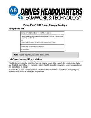
  • 1. PowerFlex® 700 Pump Energy Savings Equipment List Computer with DriveObserver and RSLinx Classic 1203-SSS Smart Self-powered Serial Adapter, 1203-SFC Serial Cable and 1202-C10 DPI Cable or 1203-USB Converter, 20-HIM-H10 Cable and USB Cable PowerFlex 700 (Series B) Drive Demo Pump Demo Note: This lab requires 230V three-phase power. Lab Objectives and Prerequisites This lab demonstrates the benefits of using a variable speed drive instead of a simple motor starter and throttle to control flow in a pumping system. Variable speed drive systems save mechanical wear and a great deal of energy. Students should have some experience with DriveObserver and RSLinx software. Performing the DriveObserver lab would satisfy this requirement.
  • 2. 2 Document Conventions Throughout this workbook, we have used the following conventions to help guide you through the lab materials. This style or symbol: Indicates: ATTENTION: Identifies information about practices or circumstances that can lead to personal injury or death, property damage, or economic loss. Attentions help you:  identify a hazard  avoid the hazard  recognize the consequences ! Words shown in bold (e.g., DriveObserver or OK) Any item or button that you must click on, or a menu name from which you must choose an option or command. This will be an actual name of an item that you see on your screen or in an example. Words shown in bold italics, enclosed in single quotes (e.g., 'Controller1') An item that you must type in the specified field. This is information that you must supply based on your application (e.g., a variable). Note: When you type the text in the field, remember that you do not need to type the quotes; simply type the words that are contained within them (e.g., Controller1). The text that appears inside of this gray box is supplemental information regarding the lab materials, but not information that is required reading in order for you to complete the lab exercises. The text that follows this symbol may provide you with helpful hints that can make it easier for you to use this product. Most often, authors use this “Tip Text” style for important information they want their students to see. Note: If the mouse button is not specified in the text, you should click on the left mouse button.
  • 3. 3 Setting-up the Demo Connecting and Energizing the Demo ATTENTION: Hazardous voltages exist beneath the drive cover. Contact with circuits under the cover can result in death or serious injury by electric shock. Do NOT remove the drive cover. ! 1. De-energize the drive. 2. Connect the 1203-SSS serial converter. If you are using the 1203-USB communications adapter, skip to the next step. 1. Connect the d-shell end of the 1203-SFC cable to the COM1 serial port on the computer. 2. Connect the other end to the 1203-SSS serial converter. 3. Connect the one end of the 20-HIM-H10 cable to the drive. 4. Connect the other end to the 1203-SSS serial converter.
  • 4. 4 5. Connect the 1203-USB converter.  Connect the A style (larger) end of the USB cable to a USB port on the computer.  Connect the B style (smaller) end of the USB cable to the converter.  Connect the RJ45 end of the 20-HIM-H10 cable to the drive.  Connect the other end to the converter.
  • 5. 5 6. Prepare the control switches. Position IN4 and IN5 switches in the LEFT (Off) position. By default these inputs command the drive to run at preset speeds. Positioning these in the LEFT position, allows you to control the drive speed with the potentiometer. Position the IN6 switch in the RIGHT (On) position. This will turn the “Enable” input on, allowing the drive to run.
  • 6. 7. Make the following connections as shown below:  Motor to the External Motor connector on back of the drive demo.  Flow sensor to External I/O connector on back of drive demo.  230V ac power to the drive demo. 8. Apply power to the drive demo by pulling the red EMERGENCY STOP on the Power Loss 6 demo.
  • 7. 7 Configuring RSLinx 1. If you are using a 1203-SSS communications adapter, note which serial port it is connected to. 2. If you are using a 1203-USB converter, determine which serial port is assigned to it:  Open the Windows Control Panel and double-click on System.  In the System Properties window, click on the Hardware tab and then click Device Manager.  In the Device Manager treeview, expand the Port (COM & LPT) group. The assigned COM port is shown in parenthesis at the end of the Allen-Bradley 1203-USB entry. 3. Start RSLinx Classic. Double-click on RSLinx icon on your desktop or in the Windows Start menu select Programs > Rockwell Software > RSLinx > RSLinx to start RSLinx. Typically, you need to configure RSLinx settings only once on each PC unless your communication connection method changes. 4. In the menus, select Communications > Configure Drivers. The Configure Drivers dialog box will open. 5. Look in the list of Configured Drivers. If you see a driver whose name begins with “AB_DF1”, select it and click Delete. 6. In the Available Drivers selection box, select “RS-232 DF1” and click Add New. 7. When prompted for a name, click OK.
  • 8. 8. Enter the appropriate data in the Configure RS-232 DF1 Devices dialog box.  Select 1770-KF2/1785-KE/SCANport for Device.  If you are using a 1203-SSS communications adapter select the Comm Port where the adapter is wired, and then select 38400 for the Baud rate.  If you are using a 1203-USB converter, select the serial port assigned to the driver for Comm Port, and then select 115200 for the Baud Rate. 8  Click OK to close the dialog box.
  • 9. 9. Verify that the driver that you just configured is listed in the Configured Drivers list with a status of 9 “Running”. Note: If the Status is “Conflict”, other software may be using the serial communication port or you may have two RSLinx serial drivers programmed for the same serial port:  Delete duplicate drivers  If another serial software package, such as DriveExplorer, is running, close it.  Then stop and re-start the RSLinx serial driver. 10. Click Close, to close the Configure Drivers dialog. 11. In the menus, select Communications > RSWho…. The RSWho dialog will open. You should see both a computer (Workstation) and the connected drive device (AB_DF1-1, Data Highway Plus). If this is not the case, verify that you have properly connected the PC to the drive using the adapter and that power to the drive is on. If you check all these things and the connected drive device still does not appear, verify your device driver settings and try other baud rates (i.e. 9600, 19200, 38400) and computer communication ports (i.e. COM1, COM2). Note: At this time, the drive device may be depicted by a question mark icon labeled “Unrecognized Device”. The serial driver will work. Note: If you cannot get the drive device to appear and communicate, contact an instructor. 12. Close RSLinx.
  • 10. Using DriveExecutive to Configure the Drive 1. Double-click the DriveExecutive icon to start the software. 2. If the Danger dialog appears, read it and click OK. 3. Maximize the DriveExecutive window, so it fills the entire screen. Connecting to the Drive with DriveExecutive 10 1. Select Drive > Connect to Drive… The Connect to Drive window will open. Click on the AB-DF1 driver you created. 2. Expand the device tree under your AB-DF1 driver. A. Click once on the AB DPI object (this is the converter connected to the drive), and click OK.
  • 11. B. Wait while the software uploads the settings in the drive. C. After the software has connected to the drive it will display a window like this: 11
  • 12. Resetting the Drive’s Settings to Factory Defaults 1. In the linear list view, locate parameter 197 [Reset To Defaults]. Change its value to 1 – Factory, 12 and press enter. 2. Clear the resulting fault by pressing the button on the drive’s Human Interface Module (HIM). Configuring the Drive
  • 13. Using DriveObserver to Monitor the Drive To perform this portion of the lab, you will use DriveObserver software. 1. Double-click the DriveObserver icon on the Windows desktop (or in the Windows Start menu select Programs > DriveTools > DriveObserver) to start the software. 2. Select File > New. The Set New Chart Sampling screen will open. 3. Select a sampling period of 300 milliseconds. Leave all the other settings as is, then click OK. Adding Traces 1. If a file is not already open, select File > New. 2. If the Add Trace screen is not already open, select Chart >Add traces… 3. In the Add Trace screen, click the Add Node button. 4. Navigate from the Workstation, through the AB_DF1 driver to the drive (address 01) and double-click on the icon for the AB DPI object (the drive). 5. Back in the Add Trace screen, select the following parameters from the linear list of the node by clicking the checkbox in front of the desired parameters: 1 [Output Freq], 3 [Output Current], 12 [DC Bus Voltage], and 415 [Encoder Spd]. 13 6. Click OK. Recording Data 1. Start the drive by pressing the button on the HIM. 2. In the DriveObserver toolbar, click the Record button. DriveObserver now displays new data. 3. If you want to stop recording data, click the Stop button. TIP: Double clicking a parameter in the table beneath the chart will open the Edit Trace screen, so that you can change the color, minimum & maximum values, line format, etc.
  • 14. Default Power Response and Logic Ride Through 1. On the Power Loss Demo set the DROPOUT TIME selector switch to 1/60, and the MULTIPLIER thumbwheel to X 2 to create a power interruption time of 33 ms. 2. Start the drive by pressing the button on the HIM, and run the motor at 60 Hz. (use the speed potentiometer to the right of the drive to get to 60 HZ). 3. If DriveObserver is not already recording, start recording data. 4. Remove input power to the drive for 33ms by pressing the SINGLE SHOT button on the Power 14 Loss Demo module. 5. Using DriveObserver, observe the output frequency and bus voltage during the power interruption. Also note whether the drive experienced a fault. 6. Repeat the above steps for an interruption of 1.5 seconds (1/2 X 3 on the Power Loss demo module). Clear any faults by pressing the button on the drive’s HIM if necessary. 7. Disable the Under Voltage Fault by resetting parameter 238 [Fault Config 1] / bit 1 [UnderVoltage] to a value of 0. Then, retest with a power interruption for 1.5 seconds. 8. Stop the drive by pressing the button on the drive’s HIM.
  • 15. 15 Inertia Ride-Through When a drive, which has been configured for inertia ride through, senses an interruption in incoming power, it can reduce the output frequency and convert the kinetic energy of the load’s inertia into electrical energy to maintain the dc bus voltage. 1. Change the value of parameter 184 [Power Loss Mode] to a value of 1 – Decel. This enables inertia ride through. 2. Enable the Power Loss Fault. Set parameter 238 [Fault Config 1] bit 0 [Power Loss] to a 1. 3. Set the Power Loss demo module to 1/2 X 8 or 4 seconds. 4. Start drive and run the motor at 60 Hz. If DriveObserver has stopped recording, restart it. 5. Remove input power to the drive for 4 seconds by pressing the SINGLE SHOT button on the Power Loss Demo module. Observe the performance of the drive. 6. Increase the value of parameter 185 [Power Loss Time] from 0.5 seconds to 6 seconds. Repeat the above steps and observe the performance of the drive. 7. Estimate the inertia ride through time for 60 Hz (1800 RPM).  Start by calculating the Moment of Inertia (J) of the flywheel. Mass (m) = 14.5 kg Radius (r) = 0.1524 meters. J = kgm2.  Calculate the Stored Energy (W) Speed (n) = 1800 RPM. W = watt-seconds.
  • 16.  The average power consumption for the drive and motor is 100 watts. Understand that this figure includes friction and windage losses in the motor, which vary with motor speed. 16  Estimate the Ride through Time. Time (in seconds) = Stored Energy (in watt-seconds) / Average Power Consumed (in watts). Estimated ride through time =_________________________________. 8. Change the value of parameter 185 [Power Loss Time], so it exceeds the time you calculated in the last step. Run the drive in ride through mode and remove power. Measure and compare the time against your calculated value. Push and hold the INFINITE button to remove input power. On the drive’s HIM, watch the value of parameter 415 [Encoder Speed]. When the value approaches zero (about 5 Hz), release the drop out button. Experiment to determine how long you can hold the button without tripping the drive.
  • 17. 17 Flying Start 1. Change the value of parameter 184 [Power Loss Mode] to 0 - Coast. 2. Change the value of parameter 155 [Stop/Brk Mode A] to 0 - Coast. 3. Start the drive and run at 60 Hz. If DriveObserver has stopped recording, restart it. 4. Press the stop button and wait ten seconds. Press the green start button. Observe the operation of the drive. 5. Stop the drive, then change the value of parameter 169 [Flying Start En] to 1 - Enabled. 6. Start the drive and run at 60 Hz. If DriveObserver has stopped recording, restart it. 7. Press the stop button and wait ten seconds. 8. Press the green start button. Observe the operation of the drive.
  • 19. www.rockwellautomation.com Power, Control and Information Solutions Americas: Rockwell Automation, 1201 South Second Street, Milwaukee, WI 53204-2496 USA, Tel: (1) 414.382.2000, Fax: (1) 414.382.4444 Europe/Middle East/Africa: Rockwell Automation SA/NV, Vorstlaan/Boulevard du Souverain 36, 1170 Brussels, Belgium, Tel: (32) 2 663 0600, Fax: (32) 2 663 0640 Asia Pacific: Rockwell Automation, Level 14, Core F, Cyberport 3, 100 Cyberport Road, Hong Kong, Tel: (852) 2887 4788, Fax: (852) 2508 1846 Publication DHQ-DM032D-EN-P – December 2006 Copyright © 2006 Rockwell Automation, Inc. All Rights Reserved. Printed in USA.