Sistema electrico 950 h
•
2 gostaram•1,213 visualizações

Maquinaria pesada-Cargador frontal

Recomendados
Recomendados
Mais conteúdo relacionado
Mais procurados
Mais procurados (20)
Semelhante a Sistema electrico 950 h
Semelhante a Sistema electrico 950 h (20)
Último
Último (20)
Sistema electrico 950 h
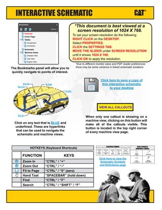
- 1. Click here to view the Schematic Symbols and Definitions page INTERACTIVE SCHEMATIC The Bookmarks panel will allow you to quickly navigate to points of interest. Click on any text that is BLUE and underlined. These are hyperlinks that can be used to navigate the schematic and machine views. When only one callout is showing on a machine view, clicking on this button will make all of the callouts visible. This button is located in the top right corner of every machine view page. VIEW ALL CALLOUTS Cover Page Tables Schematic Machine Views Component Connector Chassis View Cab View Engine View Features Options Bookmarks X EC-C3 EC-C2 E-C60 EC-C1 E-C61 To set your screen resolution do the following: RIGHT CLICK on the DESKTOP. Select PROPERTIES. CLICK the SETTINGS TAB. MOVE THE SLIDER under SCREEN RESOLUTION until it shows 1024 X 768. CLICK OK to apply the resolution. *This document is best viewed at a screen resolution of 1024 X 768. *Due to different monitor sizes and PDF reader preferences there may be some variance in linked schematic locations FUNCTION Zoom In HOTKEYS (Keyboard Shortcuts) Zoom Out Fit to Page Hand Tool “CTRL” / “+” KEYS “CTRL” / “-” “CTRL” / “0” (zero) “SPACEBAR” (hold down) Find “CTRL” / “F” Pressure Switch Temperature Switch Level Switch Flow Switch Circuit Breaker T ELECTRICAL SYMBOLS Spring (Adjustable) Variability Fluid Conditioner Pump or Motor BASIC HYDRAULIC COMPONENT SYMBOLS Click here to save a copy of this interactive schematic to your desktop Search “CTRL” / “SHIFT” / “F”
- 2. SCHEMATIC SYMBOLS AND DEFINITIONS HYDRAULIC SYMBOLS - ELECTRICAL Transducer (Fluid) Transducer (Gas / Air) G Generator Electrical Wire Pressure Switch M Electric Motor Pressure Switch (Adjustable) Temperature Switch Pressure Switch Temperature Switch Level Switch Flow Switch Circuit Breaker T ELECTRICAL SYMBOLS Spring Control Valves Restriction Line Restriction (Fixed) 2-Section Pump MAIN AUX. Spring (Adjustable) Variability Line Restriction (Variable) Pressure Compensation Pump: Variable and Pressure Compensated Hydraulic Pneumatic Energy Triangles Fluid Conditioner Attachment Pump or Motor BASIC HYDRAULIC COMPONENT SYMBOLS Line Restriction Variable and Pressure Compensated Vented Pressurized Return Above Fluid Level Return Below Fluid Level FLUID STORAGE RESERVOIRS Pressure Temperature Flow MEASUREMENT Unidirectional Bidirectional ROTATING SHAFTS One Position Two Position Three Position Two-way Three-Way Four-Way ENVELOPES PORTS CONTROL Basic Symbol Spring Loaded Normal Position A B P T A B P T Shifted Position Infinite Position Shuttle Pilot Controlled VALVES CHECK Solenoid or Manual Solenoid and Pilot Solenoid and Pilot or Manual Solenoid Servo Thermal Detent COMBINATION CONTROLS T Fuse: A component in an electrical circuit that will open the circuit if too much current flows through it. Switch (Normally Open): A switch that will close at a specified point (temp, press, etc.). The circle indicates that the component has screw terminals and a wire can be disconnected from it. Switch (Normally Closed): A switch that will open at a specified point (temp, press, etc.). No circle indicates that the wire cannot be disconnected from the component. Ground (Wired): This indicates that the component is connected to a grounded wire. The grounded wire is fastened to the machine. Ground (Case): This indicates that the component does not have a wire connected to ground. It is grounded by being fastened to the machine. Reed Switch: A switch whose contacts are controlled by a magnet. A magnet closes the contacts of a normally open reed switch; it opens the contacts of a normally closed reed switch. Sender: A component that is used with a temperature or pressure gauge. The sender measures the temperature or pressure. Its resistance changes to give an indication to the gauge of the temperature or pressure. Relay (Magnetic Switch): A relay is an electrical component that is activated by electricity. It has a coil that makes an electromagnet when current flows through it. The electromagnet can open or close the switch part of the relay. Solenoid: A solenoid is an electrical component that is activated by electricity. It has a coil that makes an electromagnet when current flows through it. The electromagnet can open or close a valve or move a piece of metal that can do work. Magnetic Latch Solenoid: An electrical component that is activated by electricity and held latched by a permanent magnet. It has two coils (latch and unlatch) that make electromagnet when current flows through them. It also has an internal switch that places the latch coil circuit open at the time the coil latches. BASIC ELECTRICAL COMPONENT SYMBOLS Push-pull Lever PedalGeneral Manual Push Button SpringManual Shutoff MANUAL CONTROL External Return Internal Return Simplified Complete Internal Supply Pressure RELEASED PRESSURE REMOTE SUPPLY PRESSURE PILOT CONTROL Spring Loaded Gas Charged ACCUMULATORS Crossing Joining LINES Double ActingSingle Acting CYLINDERS Unidirectional Bidirectional FIXED DISPLACEMENT VARIABLE DISPLACEMENT NON- COMPENSATED PUMPS Unidirectional Bidirectional Unidirectional Bidirectional FIXED DISPLACEMENT VARIABLE DISPLACEMENT NON- COMPENSATED MOTORS Unidirectional Bidirectional Two Position Infinite Positioning FLOW IN ONE DIRECTION FLOW ALLOWED IN EITHER DIRECTION Three Position CROSS FLOW PARALLEL FLOW INTERNAL PASSAGEWAYS 1 2 AG-C4 111-7898 L-C12 3E-5179 9X-1123 Component Part Number Pin or Socket Number Part Number: for Connector Plug Harness Identification Letter(s): (A, B, C, AA, AB, AC, ...) Plug 325-AG135 PK-14 Wire Color Wire Gauge Receptacle 1 1 2 2 Sure-Seal connector: Typical representation of a Sure-Seal connector. The plug and receptacle contain both pins and sockets. Deutsch connector: Typical representation of a Deutsch connector. The plug contains all sockets and the receptacle contains all pins. Fuse (5 Amps) 5A Harness identification code: This example indicates wire group 325, wire 135 in harness "AG". L-C12 3E-5179 Wire, Cable, or Harness Assembly Identification: Includes Harness Identification Letters and Harness Connector Serialization Codes (see sample). Harness Connector Serialization Code: The "C" stands for "Connector" and the number indicates which connector in the harness (C1, C2, C3, ...) HARNESS AND WIRE SYMBOLS
- 3. Electrical System 950H and 962H Wheel Loader 950H: MXL1-UP JLX1-UP 962H: SSA1-UP PCW1-UP © 2018 Caterpillar All Rights Reserved CAT, CATERPILLAR, their respective logos, “Caterpillar Yellow”, and the POWER EDGE trade dress as well as corporate and product identity used herein, are trademarks of Caterpillar and may not be used without permission. Volume 2 of 2: Chassis Wiring Volume 1 of 2: Cab Wiring April 2018 UENR2503-02
- 4. Volume 1 of 2 - CAB WIRING COMPONENT LOCATION Component Schematic Location Machine Location Component Schematic Location Machine Location Alarm - Action D-13 1 Switch - Blower Fan Speed C-7 58 Alarm - Quick Coupler D-1 2 Switch - Down Shift E-6 59 Arc Suppressor - Forward Horn G-6 3 Switch - Fine Modulation 1 G-7 60 Arc Suppressor - Hazard D-13 4 Switch - Fine Modulation 2 E-7 61 Arc Suppressor - Hazard LED Panel F-1 5 Switch - FNR F-6 62 Arc Suppressor - Turn Signal 1 D-13 6 Switch - Forward Horn 1 H-6 63 Arc Suppressor - Turn Signal 2 D-13 7 Switch - Forward Horn 2 F-6 64 Block AS - Fuse A-14 8 Switch - Hazard Lamp F-3 65 Control GP - Implement E-11 9 Switch - Heated Mirror D-2 66 Control GP - Joystick H-6 10 Switch - HID Lamp C-7 67 Control GP - Machine J-16 11 Switch - HVAC Select C-7 68 Control GP - Monitor (Messenger) C-6 12 Switch - Implement Lockout 1 H-7 69 Control GP - Payload E-4 13 Switch - Implement Lockout 2 F-7 70 Control GP - Product Link H-11 14 Switch - Key Start F-3 71 Control Gp - Transmission (HMU STEERING) G-3 15 Switch - Lift Tilt Kickout Set D-1 72 Control Gp - Transmisson G-3 181 Switch - Low / Hi Beam D-6 73 Converter - Power 1 F-14 16 Switch - Mode Select I-3 74 Converter - Power 2 E-13 17 Switch - Neutralizer Override C-2 75 Display Gp - Camera H-13 182 Switch - Payload Clear Store A-4 76 Element As - Heater H-3 183 Switch - Payload Reweigh Zero C-6 77 Flasher - 24V D-13 18 Switch - Quick Coupler D-1 78 Ground - Cab 1 A-10 19 Switch - Rear Wiper Washer C-3 79 Ground - Cab 2 A-10 20 Switch - Ride Control C-2 80 Ground - Cab 4 I-13 21 Switch - Running Lamp I-3 81 Ground - Cab 5 G-10 184 Switch - Secondary Steering Test C-2 82 Ground - Dash J-4 22 Switch - Stop Lamp F-1 83 Ground - Eng End Frame I-13 23 Switch - Third Func Cont I-3 84 Ground - Upper Cab A-3 24 Switch - Turn Signal H-2 85 Horn - Implement Audible Alert D-13 25 Switch - Wiper B-7 86 Indicator Panel - LH J-1 26 Thermostat (HVAC) I-14 87 Indicator Panel - RH H-1 27 Module Gp - Display E-7 185 Fuse - Air Seat B-4 191 Module GP - Display (Gauge Cluster) I-1 28 Fuse - Axle Oil Cooler Clutch B-4 192 Module GP - MSS E-3 29 Fuse - Beacon / Heated Mirrors B-4 193 Motor - Blend Door Actuator J-14 30 Fuse - Cluster ECM B-4 194 Motor - Blower J-14 31 Fuse - ECAP B-4 195 Motor - Front Wiper G-1 32 Fuse - ECM Switched PWR B-4 196 Motor - Rear Wiper I-13 33 Fuse - Engine ECM B-4 197 Potentiometer AS - Temp Control B-7 34 Fuse - Front / Rear Wiper / Washer B-4 198 Relay - Axle Cooler C-13 35 Fuse - Front Cab Floodlamps B-4 199 Relay - Forward Cab Floodlamp C-13 36 Fuse - HMU Shift Handle B-4 200 Relay - Forward Horn C-13 37 Fuse - Hood Actuator B-4 201 Relay - Heated Mirror C-13 38 Fuse - Horn B-4 202 Relay - Rear Cab Floodlamp C-13 39 Fuse - HVAC B-4 203 Relay - Variable Pitch Fan E-14 40 Fuse - Implement ECM B-4 204 Resistor - Blower I-14 41 Fuse - Key Start / Product Link B-4 205 Resistor - Can A I-5 42 Fuse - Lever Sensors / LH Brake Pedal Sensors B-4 206 Resistor - Can B B-4 43 Fuse - LH Tail Lamps B-4 207 Resistor 1 J-13 44 Fuse - LH/RH Dash Indicator Panel B-4 208 Resistor 2 J-13 45 Fuse - MSS / Product Link B-4 209 Sensor - 3rd Lever Position E-6 46 Fuse - Payload Control System B-4 210 Sensor - LH Brake Pedal F-1 47 Fuse - Quick Coupler B-4 211 Sensor - Lift Lever Position F-6 48 Fuse - Rear Cab Floodlamps B-4 212 Sensor - Throttle Position F-1 49 Fuse - Rear Vision B-4 213 Sensor - Tilt Lever Position F-6 50 Fuse - Secondary Steering B-4 214 Socket - Auxiliary Power E-3 186 Fuse - Spare B-4 215 Switch - Auto Dig Kickout Set C-1 52 Fuse - Stop Lamps / Dome Lamps B-4 216 Switch - Auto Dig Mode D-3 53 Fuse - Tilt / Lift Position Sensors B-4 217 Switch - Auto Dig Mode Select C-1 54 Fuse - Transmission ECM B-4 218 Switch - Auto Man Gear Sel C-3 55 Fuse - TS Flasher / Front Rear Flood Relays B-4 219 Switch - Auto Reverse Fan C-1 51 Fuse - Voltage Convertor Memory (ATCH) B-4 220 Switch - Autodig Trigger F-6 56 Fuse - Voltage Convertor memory (STD) B-4 221 Switch - Beacon F-3 57 Fuse - Voltage Convertor / 24V Radio B-4 222 Fuse Block
- 5. Volume 2 of 2 - CHASSIS WIRING COMPONENT LOCATION Component Schematic Location Machine Location Component Schematic Location Machine Location Actuator - Belly Guard J-11 88 Sensor - Fuel Pressure C-13 134 Alarm - Backup G-13 89 Sensor - Hyd Oil Temp H-5 135 Alternator H-9 90 Sensor - Input Speed H-6 136 Arc Suppressor - Quick Coupler J-3 91 Sensor - Injection Actuation Pressure D-12 137 Arc Suppressor A-10 92 Sensor - Intake Man Air Temp D-12 138 Sensor - Lift Cyl He Press J-3 139 Arc Suppressor 1 I-7 94 Sensor - Oil Pressure C-12 140 Battery - 12V 1 J-10 95 Sensor - Output Speed (Leading) G-6 141 Battery - 12V 2 J-9 96 Sensor - Output Speed (Trailing) G-6 142 Breaker - Air Inlet Heater H-11 97 Sensor - Park Brake Press C-4 143 Breaker - Belly Guard I-11 98 Sensor - Rail Pressure D-12 144 Breaker - Hood Actuator I-11 99 Sensor - Rear Axle Oil Temp A-8 145 Breaker - Main H-11 100 Sensor - Rotary Lift Pos J-3 146 Breaker - Running Lamp I-11 101 Sensor - Rotary Tilt Position J-2 147 Sensor - Torq Conv Temp C-7 148Breaker - Unswitched Buss (Cab) H-11 103 Sensor - Turbo Inlet Pressure D-9 149Clutch GP - Axle Cooler D-9 104 Sensor - XMSN Oil Temp H-6 150Control GP - Engine F-11 105 Sensor Group - Speed C-12 151Cover GP - Air Inlet D-10 106 Solenoid - AC Clutch A-10 152Ground G-13 107 Solenoid - Aux 3rd Fun Rearward G-2 153Ground - Alternator H-8 108 Solenoid - Aux 3rd FunFwd G-2 154Ground - Engine I-8 109 Solenoid - Dump Prop H-2 155Ground - LH J-9 110 Solenoid - Injectors 1-6 E-13 156Ground - RH A-7 111 Solenoid - Lower G-2 157Ground - Secondary Steering H-7 112 Solenoid - Pilot Hyd Supp G-2 158Horn - Forward High H-3 113 Solenoid - Quick Coupler I-3 159Motor - Hood Actuator H-12 114 Solenoid - Rackback Prop H-2 160Motor - Starter I-8 115 Solenoid - Raise Prop G-2 161Pump and Motor GP - Secondary Steering H-7 116 Solenoid - Ride Control Activation H-3 162Pump AS - Front Washer C-4 117 Solenoid - Ride Control Balance H-3 163Pump AS - Rear Washer C-4 118 Solenoid - Variable Speed Fan H-8 164Pump GP - Fuel Priming Pump GP - Lub A-10 B-4 119 180 Switch - AC Press B-10 165 Receptacle - Auxiliary Start J-9 120 Switch - Actuator J-10 166 Relay - Air Inlet Heater H-11 121 Switch - Aux Ground Level Shutdown B-10 167 Relay - Backup G-14 122 Switch - Disconnect J-9 168 Relay - Hood Raise / Lower Motor Control I-10 123 Switch - Fuel Pressure C-13 169 Relay - Main H-11 124 Switch - Fuel Priming Pump A-10 170 Relay - Sec Steer Intermediate I-7 125 Switch - Ground Level Shutdown G-12 171 Switch - Hood Actuator G-12 172Resistor - DC Can 1 C-7 127 Switch - Hyd Filter Bypass C-4 173Sender - Fuel Level I-13 128 Switch - Pressure (Autolube) B-4 179 Switch - Prim Steer Press I-6 174 Sensor - Atmospheric Pressure D-12 129 Switch - Sec Steer Press I-6 175 Sensor - Boost Pressure D-12 130 Switch - XMSN Filter Bypass C-4 176 Sensor - Oil Press H-8 131 Valve GP - Clutch 1-6 H-7 177 Sensor - Coolant Temp D-12 132 Valve GP - Ether Starting C-6 178 Sensor - Front Axle Oil Temp I-2 133
- 6. Volume 1 of 2 - CAB WIRING CONNECTOR LOCATION Connector Number Schematic Location CONN 1 B-16 CONN 2 C-16 CONN 3 D-16 CONN 4 D-16 CONN 5 H-14 CONN 6 E-13 CONN 7 A-12 CONN 8 F-12 CONN 9 F-12 CONN 10 G-12 CONN 11 J-12 CONN 12 I-10 H-13 D-6 D-6 H-6 H-3 G-3 G-3 F-1 CONN 13 H-9, F-8 CONN 14 H-9, F-8 CONN 15 E-8 CONN 16 D-6 CONN 17 E-3 CONN 18 CONN 45 CONN 46 CONN 47 CONN 48 CONN 49 CONN 50 CONN 51 CONN 52 E-2
- 7. Volume 2 of 2 - CHASSIS WIRING CONNECTOR LOCATION Connector Number Schematic Location CONN 1 D-4 CONN 2 E-4 CONN 3 F-4 CONN 4 G-4 CONN 19 G-13 CONN 20 G-13 CONN 21 C-12 CONN 22 C-12 CONN 23 E-12 CONN 24 H-12 CONN 25 A-8 CONN 26 F-7 CONN 27 E-7 CONN 28 E-7 CONN 29 I-6 CONN 30 A-4 CONN 31 B-4 CONN 32 I-4 CONN 33 I-3 CONN 34 I-3 CONN 35 H-3 CONN 36 G-3 CONN 37 CONN 38 CONN 39 CONN 40 CONN 41 CONN 42 CONN 43 CONN 44 A-3 B-14 B-14 B-14 D-10 C-7 B-4 J-3 The connectors shown in this chart are for harness to harness connectors. Connectors that join a harness to a component are generally located at or near the component. See the Component Location Chart.
- 8. Volume 1 of 2 - CAB WIRING CID / MID / FMI CID Component 0168 Electrical System Voltage 0364 Head End Lift Cylinder Pressure Sensor 0591 Electrically Erasable Programmable Read Only Memory 0769 Rod End Lift Cylinder Pressure Sensor 1964 Lift Cylinder Position Sensor Component Identifiers (CID¹) Module Identifier (MID²) Payload Control System (MID No. 074) FMI No. Failure Description 0 Data valid but above normal operational range. 1 Data valid but below normal operational range. 2 Data erratic, intermittent, or incorrect. 3 Voltage above normal or shorted high. 4 Voltage below normal or shorted low. 5 Current below normal or open circuit. 6 Current above normal or grounded circuit. 7 Mechanical system not responding properly. 8 Abnormal frequency, pulse width, or period. 9 Abnormal update. 10 Abnormal rate of change. 11 Failure mode not identifiable. 12 Bad device or component. 13 Out of calibration. 14 Parameter failures. 15 Parameter failures. 16 Parameter not available. 17 Module not responding. 18 Sensor supply fault. 19 Condition not met. 20 Parameter failures. ¹The FMI is a diagnostic code that indicates what type of failure has occurred. Failure Mode Identifiers (FMI)¹ Form Number REHS0970 Payload Control: RENR6293 Machine Control: UENR0795 Title Cross Reference for Electrical Connectors:
- 9. Volume 2 of 2 - CHASSIS WIRING CID / MID / FMI CID Component 0001 Cylinder #1 Injector 0002 Cylinder #2 Injector 0003 Cylinder #3 Injector 0004 Cylinder #4 Injector 0005 Cylinder #5 Injector 0006 Cylinder #6 Injector 0041 8 Volt DC Supply 0042 Injector Actuation Valve 0091 ThrottlePositionSensor 0094 Fuel Delivery Pressure Sensor 0100 Engine Oil Pressure Sensor 0110 Engine Coolant Temperature Sensor 0164 Injector Actuation Pressure Sensor 0168 Electrical System Voltage 0172 Intake Manifold Air Temperature Sensor 0174 Fuel Temperature Sensor 0190 Engine Speed Sensor 0253 Personality Module 0261 Engine Timing Calibration 0262 5 Volt Sensor DC Power Supply 0268 Programmed Parameter Fault 0274 Atmospheric Pressure Sensor 0286 Low Oil Pressure Lamp 0342 Secondary Engine Speed Sensor 0617 Inlet Air Heater Relay 1639 Machine Security System Module 1785 Intake Manifold Pressure Sensor 2417 Ether Injection Control Solenoid Component Identifiers (CID¹) Module Identifier (MID²) Engine Control ¹ The CID is a diagnostic code that indicates which circuit is faulty. FMI No. Failure Description 0 Data valid but above normal operational range. 1 Data valid but below normal operational range. 2 Data erratic, intermittent, or incorrect. 3 Voltage above normal or shorted high. 4 Voltage below normal or shorted low. 5 Current below normal or open circuit. 6 Current above normal or grounded circuit. 7 Mechanical system not responding properly. 8 Abnormal frequency, pulse width, or period. 9 Abnormal update. 10 Abnormal rate of change. 11 Failure mode not identifiable. 12 Bad device or component. 13 Out of calibration. 14 Parameter failures. 15 Parameter failures. 16 Parameter not available. 17 Module not responding. 18 Sensor supply fault. 19 Condition not met. 20 Parameter failures. ¹The FMI is a diagnostic code that indicates what type of failure has occurred. Failure Mode Identifiers (FMI)¹ Event Code Condition E0096 HighFuelPressure E0162 HighBoostPressure E0198 LowFuelPressure E0265 UserDefinedShutdown E0360 LowEngineOilPressure E0361 HighEngineCoolantTemperature E0362 EngineOverspeed E0390 FuelFilterRestriction E0539 HighIntakeManifoldAirTemperature Event Codes Engine Control
- 10. Volume 1 of 2 - CAB WIRING SPECIFICATIONS AND RELATED MANUALS Part No. Resistance (Ohms)¹ 134-2540 Resistor: Can A Can B 120 ± .1 ¹ At room temperature unless otherwise noted. Resistor Specifications Component Description
- 11. Volume 2 of 2 - CHASSIS WIRING SPECIFICATIONS AND RELATED MANUALS Part No. Function Actuate Deactuate Contact Position 110.3 ± 13.8 kPa 69 kPa min 293 ± 35 kPa 179 kPa min 1200 kPa Max 700 ± 100 kPa 275 to 2800 kPa¹ (39.9 to 253.8 psi) (101.52 to 14.5 psi) (15.99 to 2 psi) (10 psi) (25.96 psi)(42.49 to 0.29 psi) (174.04psi) 170 to 1750 kPa¹ ( 24.65 to 253.816 psi) Off-Machine Switch Specification AC High/Low Pressure355-3148 Normally Open² 367-9074 227-6744 258-0883 Fuel Pressure Hyd Filter Bypass XMSN Filter Bypass Primary Steer Pressure Secondary Steer Pressure Normally Closed Normally Closed A-B: N / O A-C: N / C Part No. Resistance (Ohms)¹ 163-0872 Solenoid: AC Clutch 17.6 ± 0.6 134-2540 Resistor: DC Can 1 120 ± 12 251-3268 Solenoid: Ride Control Activation 33.75 ± 1.68 313-7668 Solenoid: Aux 3rd Function Forward Aux 3rd Function Rearward 5 ± 0.3 313-7668 Solenoid: Dump Prop Lower Rackback Prop Raise Prop 5 ± 0.3 322-7452 Sender: Fuel Level Empty: 240-250 Full: 28-33 328-2585 Solenoid: Injectors 1-6 0.815 ± 0.045 333-8242 Solenoid: Pilot Hyd Supp 33.75 ± 1.69 ¹ At room temperature unless otherwise noted. Resistor, Sender and Solenoid Specifications Component Description Form Number REHS0970 Starting Motor: Delco 42-MT SENR3581 Engine Control: RENR5089 Title Related Electrical Service Manuals Cross Reference for Electrical Connectors:
- 12. CALLOUT FORMAT IF APPLICABLE (52) VALVE GP - CONTROL 138-1234 Callout Number (Machine Location from Component Locations Table) Component Name Part Number SYMBOL DESCRIPTION BLADE, SPADE, RING OR SCREW TERMINAL CIRCUIT CONNECTED CIRCUIT NOT CONNECTED ELECTRICAL CONNECTION TO MACHINE STRUCTURE INTERNAL ELECTRICAL CONNECTION TO SURFACE OF COMPONENT CONNECTOR ATCH WIRE, CABLE, COMPONENT SPLICE CIRCUIT GROUPING DESIGNATIONH# ABBREV RD WH OR YL PK BK GY PU BR GN BU COLOR RED WHITE ORANGE YELLOW PINK BLACK GRAY PURPLE BROWN GREEN BLUE WIRE GROUP COLOR DESCRIPTIONS GROUND CIRCUIT WIRES THAT HAVE SYSTEM VOLTAGE WHEN THE KEY SWITCH IS OFF WIRES THAT HAVE SYSTEM VOLTAGE WHEN THE KEY SWITCH IS ON VOLTAGE CONVERTER OUTPUT CIRCUIT STARTING CIRCUIT RS-232 / RS-485 DATA LINK TRANSMISSION CONTROL CIRCUIT MACHINE SECURITY CONTROL CIRCUIT ENGINE CONTROL CIRCUIT HEATER AND AIR CONDITIONER CIRCUIT TURN SIGNAL / WIPER WASHER CIRCUIT CAT DATA LINK IMPLEMENT CONTROL CIRCUIT CAN DATA LINK A CAN DATA LINK B PAYLOAD CONTROL CIRCUIT OTHER COLOR DESCRIPTIONS HIGHWAYS Components are shown installed on a fully operable machine with the key and engine off, transmission shifter in neutral and with parking brake set. Refer to the appropriate Service Manual for Troubleshooting, Specifications and Systems Operations. VOLUME 1 of 2: CAB WIRING SCHEMATIC PART NUMBER: 376-2022, CHANGE: 00, VERSION: - THIS SCHEMATIC IS FOR THE 950H AND 962H WHEEL LOADER ELECTRICAL SYSTEM MEDIA NUMBER:UENR2503-02 Refer to the Parts Manual using a specific serial number prefix in SIS before ordering parts from this schematic. A B C D E F 1234567891011121314 G H I J A B C D E F G H I J 1516 12345678910111213141516 IDENT PART NUMBER CHG LOC NOTE A 260-9602 01 F-3 SERVICE TOOL AT 192-7805 00 G-9 AIR SEAT C 372-4873 02 L-17 MAIN CAB E 372-4845 00 G-9 IMPLEMENT POD F 192-2823 02 L-15 HVAC G 373-0497 00 I-7 IMPLEMENT POD JOYSTICK (ATTACHMENT) H 280-1436 02 L-7 CAB FLOOD LAMPS (ATTACHMENT) J 236-7775 02 L-11 BEACON (ATTACHMENT) K 280-1436 02 K-7 CAB FLOOD LAMPS (ATTACHMENT) L 280-1437 01 L-8 CAB FLOOD LAMPS (ATTACHMENT) M 280-1437 01 K-8 CAB FLOOD LAMPS (ATTACHMENT) PC 317-5591 01 D-5 PAYLOAD CONTROL SYSTEM (ATTACHMENT) T 146-1892 01 G-1 LH PEDAL STOP LAMP SWITCH W 376-3342 00 D-7 DIMMER SWITCH ( ATTACHMENT) Y 235-5506 04 K-7 CAB FLOOD LAMPS AT 192-7805 00 F-10 AIR SEAT AY 154-4563 02 I-3 TURN SIGNAL SWITCH CA 152-6432 06 H-3 COMMAND CONTROL STEERING (ATTACHMENT) CE 236-7773 02 K-9 CAB HID LIGHTING (ATTACHMENT) CF 236-6207 02 L-11 HEATED OUTSIDE MIRRORS (ATTACHMENT) CR 346-1073 00 H-3 HORN SWITCH/COMAND CONTROL STEERING EG 236-7772 01 G-15 10A VOLT CONVERTER (ATTACHMENT) RC 263-2166 01 J-14 REAR VISION CAMERA (ATTACHMENT) TC 306-5350 00 F-15 VARIABLE PITCH FAN (ATTACHMENT) WA 276-0031 01 J-12 GATEWAY PRODUCT LINK (ATTACHMENT) X 372-4874 00 D-7 DIMMER SWITCH JUMPER(ATTACHMENT) HARNESS ASSEMBLIES CONN 6 CONN 1 CONN 2 CONN 3 CONN 4 CONN 7 CONN 5 CONN 10 CONN 9 CONN 8 CONN 11 CONN 12 CONN 13 CONN 14 CONN 13 CONN 14 CONN 15 CONN 15 CONN 16 CONN 17 CONN 18 CONN 5 CONN 50 CONN 51 CONN 52 CONN 49 CONN 47 CONN 46 CONN 45 CONN 48 (11) CONTROL GP - MACHINE (31) MOTOR - BLOWER (30) MOTOR - BLEND DOOR ACTUATOR (33) MOTOR - REAR WIPER (16) CONVERTER - POWER 1 (1) ALARM - ACTION (17) CONVERTER - POWER 2 (37) RELAY - FORWARD HORN (39) RELAY - REAR CAB FLOODLAMP (38) RELAY - HEATED MIRROR (35) RELAY - AXLE COOLER (9) CONTROL GP - IMPLEMENT (10) CONTROL GP - JOYSTICK (70) SWITCH - IMPLEMENT LOCKOUT 2 (61) SWITCH - FINE MODULATION 2 (69) SWITCH - IMPLEMENT LOCKOUT 1 (60) SWITCH - FINE MODULATION 1 (3) ARC SUPPERSSOR - FORWARD HORN (63) SWITCH - FORWARD HORN 1 (64) SWITCH - FORWARD HORN 2 (56) SWITCH - AUTODIG TRIGGER (59) SWITCH - DOWN SHIFT (46) SENSOR - 3RD LEVER POS (50) SENSOR - TILT LEVER POS (48) SENSOR - LIFT LEVER POS (62) SWITCH - FNR (73) SWITCH - LOW/HI BEAM (13) CONTROL GP - PAYLOAD (42) RESISTOR - CAN A (65) SWITCH - HAZARD LAMP (15) CONTROL GP - TRANSMISSION (HMU STEERING) (57) SWITCH - BEACON (71) SWITCH - KEY START (29) MODULE GP - MSS (66) SWITCH - HEATED MIRROR (82) SWITCH - SECONDARY STEERING TEST (75) SWITCH - NEUTRALIZER OVERRIDE (80) SWITCH - RIDE CONTROL (52) SWITCH - AUTODIG KICKOUT SET (72) SWITCH - LIFT TILT KICKOUT SET (54) SWITCH - AUTODIG MODE SELECT (51) SWITCH - AUTOREV FAN (2) ALARM - QUICK COUPLER (78) SWITCH - QUICK COUPLER (27) INDICATOR PANEL - RH (20) GROUND - CAB 2 (19) GROUND - CAB 1 (21) GROUND - CAB 4(23) GROUND - ENG END FRAME (8) BLOCK AS - FUSE (25) HORN - IMPLEMENT AUDIBLE ALERT (83) SWITCH - STOP LAMP (47) SENSOR - LH BRAKE PEDAL (49) SENSOR - THROTTLE POSITION (5) ARC SUPPERSSOR - HAZARD LED PANEL (40) RELAY - VARIABLE PITCH FAN (183) ELEMENT AS - HEATER (181) CONTROL GP - TRANSMISSION (186) SOCKET - AUXILIARY POWER (185) MODULE GP - DISPLAY (36) RELAY - FORWARD CAB FLOODLAMP (34) POTENTIOMETER AS - TEMP CONTROL (86) SWITCH - WIPER WASHER (FRONT INTER) (18) FLASHER - 24V (32) MOTOR - FRONT WIPER (53) SWITCH - AUTODIG DIG MODE (6) ARC SUPPRESSOR - TURN SIGNAL 1 (7) ARC SUPPRESSOR - TURN SIGNAL 2 (24) GROUND - UPPER CAB (81) SWITCH - RUNNING LAMP (58) SWITCH - BLOWER FAN SPEED (68) SWITCH - HVAC SELECT (74) SWITCH - MODE SELECT (55) SWITCH - AUTO MAN GEAR SEL (67) SWITCH - HID LAMP (84) SWITCH - THIRD FUNC CONT (22) GROUND - DASH (85) SWITCH - TURN SIGNAL (43) RESISTOR - CAN B (77) SWITCH - PAYLOAD REWEIGH ZERO (12) CONTROL GP - MONITOR(MESSENGER) (76) SWITCH - PAYLOAD CLEAR STORE (41) RESISTOR - BLOWER (87) THERMOSTAT (HAVC) (44) RESISTOR 1 (45) RESISTOR 2 (28) MODULE GO - DISPLAY (GAUGE CLUSTER) (26) INDICATOR PANEL - LH (14) CONTROL GP - PRODUCT LINK (79) SWITCH - REAR WIPER WASHER (4) ARC SUPPERSSOR - HAZARD (184) GROUND - CAB 5 (182) DISPLAY GP - CAMERA (194) CLUSTER ECM (221) VOLTAGE CONVERTOR (216) STOP LAMPS/DOME LAMPS (207) LH TAIL/CLEARANCE LAMPS (222) VOLTAGE CONVERT0RS/24V RADIO (198) FRONT/REAR WIPER/WASH (191) AIR SEAT (217) TILT/LIFT POSITION SENSORS (209) MSS/PRODUCT LINK (193) BEACON/HEATED MIRRORS (196) ECM SWITCHED PWR (204) IMPL ECM (197) ENGINE ECM (200) HMU SHIFT HANDLE (211) QUICK COUPLER MEMORY (STANDARD) (205) KEY START SW/PRODUCT LINK (202) HORN (201) HOOD ACTUATOR (195) ECAP (210) PAYLOAD CONTROL SYSTEM (213) REAR VISION / I TERM (206) LEVER SENSORS/ (199) FRONT CAB FLOODLAMPS (208) LH/RH DASH INDICATOR PNL (219) TS FLASHER/FRNT (214) SECONDARY STEERING (212) REAR CAB FLOODLAMPS (220) VOL CONV MEMORY (ATTA) (218) XMSN ECM (192) AXLE OIL COOLER CLUTCH (203) HVAC LH BRAKE PEDAL SENSOR REAR FLOOD RELAYS (NOT USED ON 980G) (215) SPARE TERMINAL CONNECTS TO VARIABLE PITCH FAN RELAY FUSE PANEL/ELECTRICAL INSTALLATION PANEL B SERVICE TOOL CONNECTOR CAP PART NUMBER 8C-6354 NOTE: JUMPER 610-OR TO 619-GN ON MACHINES NOT EQUIPPED WITH ROADING LIGHTS. GND STRAP 8X-5802 CABLE AS. 191-5114 CABLE AS. 191-5114 CABLE AS. 124-4884 C216-E11 BK-18 C216-E11 BK-18 C216-E15 BK-18 C216-E17 BK-18 C216-E16 BK-18 164-E7 WH-18 164-E7 WH-18 164-E19 WH-18 164-E20 WH-18 164-E21 WH-18 320-E12 OR-16 320-E12 OR-16 H722-E9 GN-18 H722-E9 GN-18 H711-E2 GN-18 H711-E2 GN-18 H710-E1 PK-18 H710-E1 PK-18 IMPLEMENT POD 200-C334 BK-16 200-C334 BK-16 200-C416 BK-18 200-C416 BK-18 200-C416 BK-18 537-C56 GN-16 102-C248 RD-14 DASH DASH FUSE PANEL/ELECTRICAL INSTALLATION 537-C56 GN-16 118-C355 GY-16 118-C355 GY-16 202-C350 BK-18 202-C350 BK-18 C216-C22 BK-16 C216-C22 BK-16 308-C87 YL-18 308-C87 YL-18 308-C87 YL-18 138-C20 GN-18 138-C20 GN-18 615-C298 YL-14 615-C298 YL-14 615-C298 YL-14 615-C298 YL-14 615-C298 YL-14 615-C298 YL-14 C529-C48 GY-18 C529-C48 GY-18 C529-C59 GY-18 C529-C59 GY-18 C529-C59 GY-18 C529-C59 GY-18 C530-C49 BU-18 C530-C49 BU-18 C530-C61 BU-18 C530-C61 BU-18 C530-C61 BU-18 945-C128 BR-18 945-C128 BR-18 945-C128 BR-18 945-C128 BR-18 945-C128 BR-18 944-C127 OR-18 944-C127 OR-18 944-C127 OR-18 944-C127 OR-18 944-C127 OR-18 604-C78 OR-16 604-C78 OR-16 604-C78 OR-16 614-C82 PU-16 614-C82 PU-16 614-C199 PU-18 614-C199 PU-18 614-C199 PU-18 605-C79 YL-16 605-C79 YL-16 605-C91 YL-16 605-C91 YL-16 605-C91 YL-16 606-C80 GY-16 606-C80 GY-16 606-C89 GY-16 606-C89 GY-16 606-C89 GY-16 202-C4 BK-18 202-C4 BK-18 202-C31 BK-16 202-C31 BK-16 202-C31 BK-16 202-C31 BK-16 611-C32 PU-14 611-C32 PU-14 611-C32 PU-14 403-C123 GN-18 403-C123 GN-18 606-C89 GY-16 605-C91 YL-16 509-C340 WH-18 508-C302 PU-18 508-C302 PU-18 508-C302 PU-18 508-C302 PU-18 508-C302 PU-18 691-C326 GY-16 131-C266 BR-16 322-C39 GY-16 322-C39 GY-16 322-C39 GY-16 322-C39 GY-16 322-C39 GY-16 322-C39 GY-16 127-C267 OR-14 199-C72 RD-16 199-C72 RD-16 199-C72 RD-16 199-C72 RD-16 199-C72 RD-16 199-C72 RD-16 150-C126 OR-16 150-C126 OR-16 150-C126 OR-16 106-C18 WH-18 106-C18 WH-18 106-C18 WH-18 106-C18 WH-18 106-C18 WH-18 106-C18 WH-18 112-C1 PU-4 112-C1 PU-4 112-C1 PU-4 112-C1 PU-4 112-C1 PU-4 112-C1 PU-4 619-C40 GN-14 619-C40 GN-14 A523-C236 PU-18 A523-C236 PU-18A523-C236 PU-18 A523-C236 PU-18 A523-C236 PU-18 A524-C237 BR-18 A524-C237 BR-18A524-C237 BR-18 A524-C237 BR-18 A524-C237 BR-18 A524-C237 BR-18 A524-C237 BR-18 A525-C238 GN-18 A525-C238 GN-18A525-C238 GN-18 A525-C238 GN-18 A525-C238 GN-18 A525-C238 GN-18 A525-C238 GN-18 517-C240 BU-14 517-C240 BU-14 517-C240 BU-14 517-C240 BU-14 517-C240 BU-14 517-C240 BU-14 517-C240 BU-14 516-C241 GN-14 516-C241 GN-14516-C241 GN-14 516-C241 GN-14 516-C241 GN-14 516-C241 GN-14 516-C241 GN-14 515-C235 GY-14 515-C235 GY-14 515-C235 GY-14 515-C235 GY-14 515-C235 GY-14 515-C235 GY-14 515-C235 GY-14 522-C125 WH-18 522-C125 WH-18 522-C125 WH-18 522-C125 WH-18 522-C125 WH-18 522-C125WH-18 504-C255 YL-18 504-C255 YL-18 504-C255 YL-18 504-C255 YL-18 504-C255 YL-18 504-C255 YL-18 504-C255 YL-18 503-C256 BR-18 503-C256 BR-18 503-C256 BR-18 503-C256 BR-18 503-C256 BR-18 503-C256 BR-18 503-C256 BR-18 A982-C130 BR-18 A982-C130 BR-18 A982-C130 BR-18 A982-C130 BR-18 A307-C129 GY-18 A307-C129 GY-18 A307-C129 GY-18 A307-C129 GY-18 521-C124 YL-14 521-C124 YL-14 521-C124 YL-14 521-C124 YL-14 130-T2 RD-18 604-T1 OR-18 500-C252 BR-18 500-C252 BR-18 500-C252 BR-18 506-C10 PU-18 506-C10 PU-18 506-C10 PU-18 506-C10 PU-18 507-C11 WH-18 507-C11 WH-18 507-C11 WH-18 507-C11 WH-18 501-C257 GN-18 501-C257 GN-18 501-C257 GN-18 502-C253 OR-18 502-C253 OR-18 502-C253 OR-18 617-C83 BR-16 617-C83 BR-16 617-C83 BR-16 617-C83 BR-16 617-C83 BR-16 617-C83 BR-16 102-C69 RD-14 102-C69 RD-14 102-C69 RD-14 102-C69 RD-14 127-C267 OR-14 691-C326 GY-16 604-C78 OR-16 174-C2 RD-10 174-C2 RD-10 174-C2 RD-10 174-C2 RD-10 174-C2 RD-10 174-C2 RD-10 138-C20 GN-18 118-C274 GY-18 118-C274 GY-18 118-C274 GY-18 118-C274 GY-18 118-C274 GY-18 118-C274 GY-18 201-C224 BK-18 201-C224 BK-18 134-C268 YL-14 200-C220 BK-18 200-C220 BK-18 200-C220 BK-18 200-C220 BK-18 608-C294 GN-14 608-C294 GN-14 608-C294 GN-14 608-C294 GN-14 608-C294 GN-14 608-C294 GN-14 608-C294 GN-14 608-C294 GN-14 A272-C233 BK-14 114-C41 RD-16 114-C41 RD-16 114-C41 RD-16 114-C41 RD-16 114-C41 RD-16 114-C42 RD-16 201-C224 BK-18 200-C213 BK-16 200-C213 BK-16 200-C213 BK-16 200-C213 BK-16 200-C212 BK-18 200-C212 BK-18 200-C212 BK-18 200-C212 BK-18 200-C211 BK-16 200-C211 BK-16 200-C211 BK-16 200-C211 BK-16 200-C210 BK-18 200-C210 BK-18 200-C210 BK-18 200-C210 BK-18 200-C210 BK-18 200-C210 BK-18 200-C209 BK-14 200-C209 BK-14 200-C209 BK-14 200-C209 BK-14 200-C209 BK-14 200-C209 BK-14 134-C268 YL-14 114-C42 RD-16 136-C75 GN-16 136-C75 GN-16 136-C75 GN-16 136-C75 GN-16 136-C75 GN-16 164-E20 WH-18 C216-E16 BK-18 H722-E9 GN-18 164-E19 WH-18 C216-E15 BK-18 H711-E2 GN-18 164-E21 WH-18 C216-E17 BK-18 H710-E1 PK-18 320-E12 OR-16 200-C344 BK-18 200-C344 BK-18 200-C345 BK-18 200-C345 BK-18 727-C289 GN-16 727-C289 GN-16 727-C289 GN-16 727-C289 GN-16 200-C342 BK-18 200-C342 BK-18 C216-C314 BK-18 C216-C314 BK-18 C216-C314 BK-18 C216-C314 BK-18 200-C334 BK-16 200-C341 BK-16 A982-C130 BR-18 A307-C129 GY-18 A307-C129 GY-18 604-C78 OR-16 619-C40 GN-14 592-C202 BU-16 200-C335 BK-16 200-C335 BK-16 200-C335 BK-16 201-C292 BK-18 201-C292 BK-18 G746-C13 WH-18 G746-C13 WH-18 G746-C13 WH-18 G746-C13 WH-18 G746-C13 WH-18 202-C143 BK-18 611-C32 PU-14 973-C195 BR-18 973-C195 BR-18 973-C195 BR-18 973-C195 BR-18 977-C197 YL-18 977-C197 YL-18 977-C197 YL-18 977-C197 YL-18 H728-C198 GN-18 H728-C198 GN-18 H728-C198 GN-18 H728-C198 GN-18 720-C234 PU-18 720-C234 PU-18 720-C234 PU-18 720-C234 PU-18 H730-C201 BR-18 H730-C201 BR-18 H730-C201 BR-18 H730-C201 BR-18 G767-C190 WH-18 G767-C190 WH-18 G767-C190 WH-18 G767-C190 WH-18 P910-C38 BR-18 P910-C38 BR-18 P910-C38 BR-18 P910-C38 BR-18 G766-C189 GN-18 G766-C189 GN-18 G766-C189 GN-18 G766-C189 GN-18 592-C8 BU-16 592-C8 BU-16 592-C8 BU-16 592-C8 BU-16 G755-C186 GY-18 G755-C186 GY-18 G755-C186 GY-18 G755-C186 GY-18 G755-C186 GY-18 G750-C196 BU-18 G750-C196 BU-18 G750-C196 BU-18 G750-C196 BU-18 G750-C196 BU-18 G763-C185 PU-18 G763-C185 PU-18 G763-C185 PU-18 G763-C185 PU-18 G763-C185 PU-18 G768-C187 GN-18 G768-C187 GN-18 G768-C187 GN-18 G768-C187 GN-18 G768-C187 GN-18 G760-C191 WH-18 G760-C191 WH-18 G760-C191 WH-18 G760-C191 WH-18 G760-C191 WH-18 H729-C63 WH-18 H729-C63 WH-18 H729-C63 WH-18 H729-C63 WH-18 P976-C77 BR-16 P976-C77 BR-16 P976-C77 BR-16 P976-C77 BR-16 202-C143 BK-18 FUSE PART NUMBERS 10 AMP (9W-1442) 15 AMP (9W-1441) 20 AMP (9W-1446) C216-C148 BK-18 C216-C148 BK-18C216-C149 BK-18 C216-C149 BK-18 121-C133 RD-14 121-C150 RD-14 121-C170 RD-14 T866-C174 YL-18 T866-C174 YL-18 T866-C174 YL-18 T866-C174 YL-18 T866-C174 YL-18 944-C141 OR-18 944-C141 OR-18 944-C141 OR-18 944-C141 OR-18 945-C134 BR-18 945-C134 BR-18 945-C134 BR-18 945-C134 BR-18 H709-C158 BU-18 H709-C158 BU-18 H709-C158 BU-18H709-C158 BU-18 H708-C157 OR-18 H708-C157 OR-18 H708-C157 OR-18 H708-C157 OR-18 T859-C176 WH-18 T859-C176 WH-18 T859-C176 WH-18 T859-C176 WH-18 T858-C175 GY-18 T858-C175 GY-18 T858-C175 GY-18 T858-C175 GY-18 T858-C175 GY-18 T857-C156 GN-18 T857-C156 GN-18 T857-C156 GN-18 T857-C156 GN-18 T856-C155 WH-18 T856-C155 WH-18 T856-C155 WH-18 T856-C155 WH-18 T855-C166 BU-18 T855-C166 BU-18 T855-C166 BU-18 T855-C166 BU-18 T853-C164 OR-18 T853-C164 OR-18 T853-C164 OR-18 T853-C164 OR-18 T852-C163 GY-18 T852-C163 GY-18 T852-C163 GY-18 T852-C163 GY-18 T854-C165 YL-18 T854-C165 YL-18 T854-C165 YL-18 T854-C165 YL-18 A272-C233 BK-14 E920-C52 BR-18 E920-C52 BR-18 E920-C52 BR-18 E920-C52 BR-18 E920-C52 BR-18 E919-C51 YL-18 E919-C51 YL-18 E919-C51 YL-18 E919-C51 YL-18 E919-C51 YL-18 E921-C53 PK-18 E921-C53 PK-18 E921-C53 PK-18 E921-C53 PK-18 E921-C53 PK-18 E922-C54 GN-18 E922-C54 GN-18 E922-C54 GN-18 E922-C54 GN-18 E922-C54 GN-18 H713-C57 PK-18 H713-C57 PK-18 H713-C57 PK-18 H713-C57 PK-18 H713-C57 PK-18 H717-C67 BR-18 H717-C67 BR-18 H717-C67 BR-18 H717-C67 BR-18 H717-C67 BR-18 H714-C58 OR-18 H714-C58 OR-18 H714-C58 OR-18 H714-C58 OR-18 H714-C58 OR-18 C216-C26 BK-16 C216-C26 BK-16 C216-C26 BK-16 C216-C26 BK-16 C529-C60 GY-18 C529-C60 GY-18 C529-C60 GY-18 C529-C60 GY-18 C530-C62 BU-18 C530-C62 BU-18 C530-C62 BU-18 C530-C62 BU-18 T860-C161 OR-18T860-C161 OR-18 T860-C161 OR-18 T860-C161 OR-18 T861-C162 YL-18 T861-C162 YL-18 T861-C162 YL-18 T861-C162 YL-18 T869-C168 WH-18 T869-C168 WH-18 T869-C168 WH-18 T869-C168 WH-18 H711-C172 GN-18 H711-C172 GN-18 H711-C172 GN-18 H711-C172 GN-18 E917-C152 WH-18 E917-C152 WH-18 E917-C152 WH-18 E917-C152 WH-18 E918-C153 GN-18 E918-C153 GN-18 E918-C153 GN-18 E918-C153 GN-18 T870-C167 BR-18T870-C167 BR-18 T870-C167 BR-18 T870-C167 BR-18 H710-C171 PK-18 H710-C171 PK-18 H710-C171 PK-18 STRAP AS. 202-C113 BK-16 202-C113 BK-16 202-C113 BK-16 202-C19 BK-18 751-C115 GN-18 751-C115 GN-18 751-C115 GN-18 751-C115 GN-18 752-C111 YL-18 752-C111 YL-18 752-C111 YL-18 752-C111 YL-18 E900-C207 WH-18 E900-C207 WH-18 E900-C207 WH-18 E900-C207 WH-18 E906-C221 OR-18 E906-C221 OR-18 E906-C221 OR-18 E906-C221 OR-18 E908-C227 BR-18 E908-C227 BR-18 E908-C227 BR-18 E908-C227 BR-18 754-C142 BU-18 754-C142 BU-18 754-C142 BU-18 754-C142 BU-18 E901-C203 GN-18 E901-C203 GN-18 E901-C203 GN-18 E901-C203 GN-18 E907-C246 GY-18 E907-C246 GY-18 E907-C246 GY-18 E907-C246 GY-18 E909-C218 WH-18 E909-C218 WH-18 E909-C218 WH-18 E909-C218 WH-18 755-C120 OR-18 755-C120 OR-18 755-C120 OR-18 755-C120 OR-18 900-C147 PU-18 900-C147 PU-18 900-C147 PU-18 900-C147 PU-18 901-C121 WH-18 901-C121 WH-18 901-C121 WH-18 901-C121 WH-18 K977-C205 PK-18 K977-C205 PK-18 K977-C205 PK-18 K977-C205 PK-18 944-C110 OR-18 944-C110 OR-18 944-C110 OR-18 944-C110 OR-18 944-C110 OR-18 945-C105 BR-18 945-C105 BR-18 945-C105 BR-18 945-C105 BR-18 945-C105 BR-18 G763-C185 PU-18 G763-C185 PU-18 G755-C186 GY-18 G755-C186 GY-18 G768-C187 GN-18 G768-C187 GN-18 G766-C189 GN-18 G766-C189 GN-18 G767-C190 WH-18 G767-C190 WH-18 G760-C191 WH-18 G760-C191 WH-18 973-C195 BR-18 973-C195 BR-18 G750-C196 BU-18 G750-C196 BU-18 977-C197 YL-18 977-C197 YL-18 H728-C198 GN-18 H728-C198 GN-18 H729-C63 WH-18 H729-C63 WH-18 720-C234 PU-18 720-C234 PU-18 P910-C38 BR-18 P910-C38 BR-18 H730-C201 BR-18 H730-C201 BR-18 G746-C13 WH-18 G746-C13 WH-18 728-C106 BU-18 728-C106 BU-18 728-C106 BU-18 728-C106 BU-18 306-C109 GN-18 306-C109 GN-18 306-C109 GN-18 306-C109 GN-18 N939-C112 GN-18 N939-C112 GN-18 N939-C112 GN-18 N939-C112 GN-18 976-C116 OR-18 976-C116 OR-18 976-C116 OR-18 976-C116 OR-18 G764-C117 PK-18 G764-C117 PK-18 G764-C117 PK-18 G764-C117 PK-18 453-C119 PK-18 453-C119 PK-18 453-C119 PK-18 453-C119 PK-18 484-C140 YL-18 484-C140 YL-18 484-C140 YL-18 484-C140 YL-18 417-C183 GY-18 417-C183 GY-18 417-C183 GY-18 417-C183 GY-18 416-C184 OR-18 416-C184 OR-18 416-C184 OR-18 416-C184 OR-18 321-C249 BR-18 321-C249 BR-18 321-C249 BR-18 321-C249 BR-18 450-C263 YL-18 450-C263 YL-18 450-C263 YL-18 450-C263 YL-18 326-C287 PU-18 326-C287 PU-18 326-C287 PU-18 326-C287 PU-18 326-C287 PU-18 200-C346 BK-18 200-C346 BK-18 J1 J2 H795-C222 PK-18 516-C241 GN-14 517-C240 BU-14 A525-C238 GN-18 A524-C237 BR-18 515-C235 GY-14 521-C124 YL-14 A525-C238 GN-18 A524-C237 BR-18 517-C240 BU-14 516-C241 GN-14 515-C235GY-14 521-C124 YL-14 502-C253 OR-18 500-C252 BR-18 506-C10 PU-18 501-C257 GN-18 T855-C166 BU-18 T852-C163 GY-18 T854-C165 YL-18 T853-C164 OR-18 H729-C63 WH-18 H728-C198 GN-18 977-C197 YL-18 973-C195 BR-18 504-C255 YL-18 503-C256 BR-18 507-C11 WH-18 720-C234 PU-18 500-C252 BR-18 502-C253 OR-18 506-C10 PU-18 501-C257 GN-18 503-C256 BR-18 977-C197 YL-18 507-C11 WH-18 504-C255 YL-18 973-C195 BR-18 H728-C198 GN-18 H729-C63 WH-18 T855-C166 BU-18 T852-C163 GY-18 T854-C165 YL-18 T853-C164 OR-18 H795-C222 PK-18 720-C234 PU-18 C530-C61 BU-18 C529-C59 GY-18 P910-C38 BR-18 T857-C156 GN-18 G767-C190 WH-18 727-C289 GN-16 G766-C189 GN-18 T856-C155 WH-18 C529-C59 GY-18 C530-C61 BU-18 H730-C201 BR-18 P910-C38 BR-18 T858-C175 GY-18 T857-C156 GN-18 G767-C190 WH-18 H709-C158 BU-18 T859-C176 WH-18 T856-C155 WH-18 G766-C189 GN-18 614-C94 PU-18 727-C289 GN-16 H708-C157 OR-18 200-C344 BK-18 200-C346 BK-18 200-C342 BK-18 200-C345 BK-18 604-C78 OR-16 604-C78 OR-16 G746-C13 WH-18 617-C83 BR-16 509-C340 WH-18 509-C340 WH-18 592-C8 BU-16 308-C87 YL-18 592-C8 BU-16 G750-C196 BU-18 G755-C186 GY-18 G768-C187 GN-18 G760-C191 WH-18 G763-C185 PU-18 G750-C196 BU-18 G755-C186 GY-18 G763-C185 PU-18 G768-C187 GN-18 G760-C191 WH-18 606-C89 GY-16 605-C91 YL-16 326-C287 PU-18 606-C89 GY-16 605-C91 YL-16 326-C287 PU-18 501-C257 GN-18 502-C253 OR-18 500-C252 BR-18 502-C253 OR-18 500-C252 BR-18 501-C257 GN-18 537-C16 GN-16 537-C56 GN-16 537-C56 GN-16 537-C56 GN-16 537-C56 GN-16 537-C56 GN-16 508-C302 PU-18 508-C302 PU-18 202-C143 BK-18 202-C143 BK-18 202-C143 BK-18 202-C31 BK-16 202-C31 BK-16 102-C69 RD-14 308-C87 YL-18 104-C30 YL-16 104-C30 YL-16 104-C30 YL-16 104-C30 YL-16 104-C30 YL-16 201-C304 BK-16 201-C304 BK-16 147-A1 RD-18 200-A2 BK-18 944-A3 OR-18 945-A4 BR-18 201-C292 BK-18 307-C3 OR-18 307-C3 OR-18 307-C3 OR-18 307-C3 OR-18 307-C3 OR-18 307-C3 OR-18 307-C3 OR-18 307-C3 OR-18 307-C3 OR-18 H730-C201 BR-18 A523-C236 PU-18 A523-C236 PU-18 A523-C236 PU-18 A523-C236 PU-18 592-C392 BU-16 592-C392 BU-16 592-C392 BU-16 592-C392 BU-16 592-C392 BU-16 A982-C130 BR-18 611-C100 PU-14 202-C143 BK-18 G746-C13 WH-18 A982-C130 BR-18 A307-C129 GY-18 201-C224 BK-18 200-C312 BK-16 200-C312 BK-16 200-C312 BK-16 148-C282 RD-16 148-C282 RD-16 115-C103 PK-16 115-C103 PK-16 115-C283 PK-16 115-C283 PK-16 200-C219 BK-16 200-C219 BK-16 200-C219 BK-16 200-C219 BK-16 120-C281 RD-16 120-C281 RD-16 120-C281 RD-16 120-C281 RD-16 A513-C339 RD-16 A513-C339 RD-16 A513-C339 RD-16 A513-C339 RD-16 A513-C339 RD-16 A513-C339 RD-16 A513-C339 RD-16 A513-C339 RD-16 A513-C339 RD-16 592-C272 BU-16 592-C272 BU-16 592-C272 BU-16 592-C272 BU-16 592-C272 BU-16 TO INSURE PROPER GROUND REMOVE PAINT AND CORROSION BEFORE CONNECTING GROUND STRAP 945-C105 BR-18 944-C110 OR-18 944-C110 OR-18 945-C105 BR-18 170-C70 RD-14 170-C70 RD-14 170-C70 RD-14 170-C70 RD-14 170-C107 RD-14 170-C107 RD-14 170-C107 RD-14 170-C107 RD-14 A272-C35 BK-14 A272-C35 BK-14 A272-C35 BK-14 A272-C35 BK-14 A272-C35 BK-14 A272-C35 BK-14 139-C277 RD-16 139-C277 RD-16 139-C277 RD-16 139-C277 RD-16 139-C277 RD-16 139-C277 RD-16 139-C277 RD-16 139-C277 RD-16 139-C277 RD-16 131-C265 BR-18 131-C265 BR-18 131-C265 BR-18 131-C265 BR-18 131-C265 BR-18 131-C265 BR-18 131-C265 BR-18 131-C265 BR-18 141-C285 PK-16 141-C285 PK-16 141-C285 PK-16 141-C285 PK-16 141-C285 PK-16 141-C285 PK-16 141-C285 PK-16 105-C259 RD-16 105-C259 RD-16 105-C259 RD-16 105-C259 RD-16 105-C259 RD-16 105-C259 RD-16 105-C259 RD-16 105-C259 RD-16 168-C68 GN-16 168-C68 GN-16 168-C68 GN-16 168-C68 GN-16 168-C68 GN-16 168-C68 GN-16 168-C68 GN-16 168-C68 GN-16 164-C264 WH-18 164-C264 WH-18 164-C264 WH-18 164-C264 WH-18 164-C264 WH-18 164-C264 WH-18 164-C264 WH-18 164-C264 WH-18 115-C280 PK-16 115-C280 PK-16 115-C280 PK-16 115-C280 PK-16 115-C280 PK-16 115-C280 PK-16 115-C280 PK-16 130-C5 RD-16 130-C5 RD-16 130-C5 RD-16 130-C5 RD-16 118-C258 GY-16 118-C258 GY-16 118-C258 GY-16 118-C258 GY-16 147-C73 RD-18 147-C73 RD-18 147-C73 RD-18 147-C73 RD-18 147-C73 RD-18 147-C73 RD-18 147-C73 RD-18 518-C329 OR-16 518-C329 OR-16 518-C329 OR-16 518-C329 OR-16 518-C329 OR-16 518-C329 OR-16 518-C329 OR-16 538-C331 BR-16 538-C331 BR-16 538-C331 BR-16 538-C331 BR-16 538-C331 BR-16 538-C331 BR-16 606-C88 GY-16 606-C88 GY-16 606-C88 GY-16 606-C88 GY-16 606-C88 GY-16 605-C90 YL-16 605-C90 YL-16 605-C90 YL-16 605-C90 YL-16 605-C90 YL-16 615-C291 YL-14 615-C291 YL-14 615-C291 YL-14 615-C291 YL-14 615-C291 YL-14 646-C293 OR-18 646-C293 OR-18 646-C293 OR-18 646-C293 OR-18 646-C293 OR-18 646-C293 OR-18 646-C293 OR-18 646-C293 OR-18 646-C293 OR-18 647-C290 GN-18 647-C290 GN-18 647-C290 GN-18 647-C290 GN-18 647-C290 GN-18 647-C290 GN-18 647-C290 GN-18 647-C290 GN-18 647-C290 GN-18 944-C144 OR-18 944-C144 OR-18 944-C144 OR-18 944-C144 OR-18 944-C144 OR-18 944-C144 OR-18 944-C144 OR-18 944-C144 OR-18 944-C28 OR-18 944-C28 OR-18 944-C28 OR-18 944-C28 OR-18 944-C28 OR-18 944-C28 OR-18 944-C28 OR-18 944-C28 OR-18 945-C136 BR-18 945-C136 BR-18 945-C136 BR-18 945-C136 BR-18 945-C136 BR-18 945-C136 BR-18 945-C136 BR-18 945-C136 BR-18 945-C17 BR-18 945-C17 BR-18 945-C17 BR-18 945-C17 BR-18 945-C17 BR-18 945-C17 BR-18 945-C17 BR-18 945-C17 BR-18 136-C310 GN-16 136-C310 GN-16 136-C310 GN-16 136-C310 GN-16 136-C310 GN-16 136-C310 GN-16 136-C310 GN-16 136-C310 GN-16 138-C37 GN-18 138-C37 GN-18 138-C37 GN-18 138-C37 GN-18 138-C37 GN-18 138-C43 GN-18 138-C43 GN-18 138-C43 GN-18 138-C43 GN-18 138-C43 GN-18 200-C204 BK-14 200-C204 BK-14 200-C204 BK-14 200-C204 BK-14 200-C309 BK-16 200-C309 BK-16 200-C309 BK-16 200-C309 BK-16 122-C278 RD-16 122-C278 RD-16 122-C278 RD-16 164-C276 WH-18 164-C276 WH-18 164-C276 WH-18 164-C276 WH-18 164-C276 WH-18 164-C276 WH-18 108-C271 BU-14 108-C271 BU-14 108-C271 BU-14 108-C271 BU-14 108-C271 BU-14 108-C271 BU-14 108-C271 BU-14 118-C275 GY-18 118-C275 GY-18 118-C275 GY-18 118-C275 GY-18 118-C275 GY-18 118-C275 GY-18 STRAPAS. ECM MOUNT BOLT ECM MOUNT BOLT 200-C288 BK-18 H709-C158 BU-18 H708-C157 OR-18 614-C94 PU-18 PANEL B IMPLEMENT POD 102-C248 RD-14 614-C330 PU-16 614-C330 PU-16 H795-C222 PK-18 H795-C222 PK-18 H795-C222 PK-18 509-C340 WH-18 509-C340 WH-18 509-C340 WH-18 509-C340 WH-18 H722-C301 GN-18 H722-C301 GN-18 H722-C301 GN-18 H722-C301 GN-18 H722-C301 GN-18 164-G8 WH-18 164-G8 WH-18 C216-G9 BK-18 C216-G9 BK-18 H711-G10 GN-18 H711-G10 GN-18 H711-G10 GN-18 H710-G13 PK-18 H710-G13 PK-18 H710-G13 PK-18 H722-G3 GN-18 H722-G3 GN-18 H722-G3 GN-18 200-G4 BK-16 320-G7 OR-16 320-G7 OR-16 H795-C222 PK-18 102-C248 RD-14 102-C131 RD-16 102-C131 RD-16 102-C131 RD-16 537-C16 GN-16 537-C16 GN-16 537-C305 GN-16 537-C305 GN-16 537-C305 GN-16 124-C23 GN-14 124-C23 GN-14 124-C23 GN-14 124-C23 GN-14 124-C23 GN-14 124-C23 GN-14 124-C23 GN-14 C542-C393 GN-16 C542-C393 GN-16 C542-C393 GN-16 C583-C395 GN-18 C583-C395 GN-18 C583-C395 GN-18 141-C397 PK-16 141-C397 PK-16 202-C396 BK-18 202-C396 BK-18 T859-C176 WH-18 T858-C175 GY-18 134-C337 YL-14 134-C337 YL-14 134-C337 YL-14 134-C337 YL-14 134-C337 YL-14 127-C336 OR-14 127-C336 OR-14 127-C336 OR-14 127-C336 OR-14 320-C390 OR-16 320-C390 OR-16 320-C390 OR-16 C216-C365 BK-18 C216-C365 BK-18 202-C358 BK-18 202-C358 BK-18 202-C358 BK-18 A629-C300 BU-14 A629-C300 BU-14 A629-C300 BU-14 A629-C300 BU-14 615-C239 YL-14 615-C239 YL-14 615-C239 YL-14 615-C239 YL-14 200-G17 BK-16 200-G17 BK-16 320-G18 OR-16 320-G18 OR-16 320-G19 OR-16 320-G19 OR-16 C542-C393 GN-16 IMPLEMENT POD (JOYSTICK) -ATCH 118-C355 GY-16 C530-C61 BU-18 A525-C238 GN-18 A524-C237 BR-18 517-C240 BU-14 614-C94 PU-18 503-C256 BR-18 504-C255 YL-18 515-C235 GY-14 516-C241 GN-14 502-C253 OR-18 720-C234 PU-18 T857-C156 GN-18 G766-C189 GN-18 P976-C77 BR-16 G767-C190 WH-18 H709-C158 BU-18 168-C68 GN-16 138-C37 GN-18 138-C43 GN-18 124-C23 GN-14 C216-C365 BK-18 C583-C395 GN-18 506-C10 PU-18 500-C252 BR-18 507-C11 WH-18 202-C396 BK-18 A523-C236 PU-18 202-C350 BK-18 H708-C157 OR-18 727-C289 GN-16 T856-C155 WH-18 501-C257 GN-18 T859-C176 WH-18 973-C195 BR-18 977-C197 YL-18 521-C124 YL-14 H728-C198 GN-18 H729-C63 WH-18 T855-C166 BU-18 T852-C163 GY-18 H730-C201 BR-18 T854-C165 YL-18 T853-C164 OR-18 P910-C38 BR-18 118-C354 GY-18 118-C354 GY-18 118-C354 GY-18 118-C353 GY-18 118-C353 GY-18 118-C353 GY-18 200-C384 BK-18 H710-C171 PK-18 126-C299 PK-16 126-C299 PK-16 126-C299 PK-16 126-C299 PK-16 126-C299 PK-16 126-C299 PK-16 126-C299 PK-16 126-C299 PK-16 126-C299 PK-16 614-C7 PU-18 614-C7 PU-18 614-C7 PU-18 603-C297 PK-16 603-C297 PK-16 603-C297 PK-16 603-C297 PK-16 603-C297 PK-16 603-C297 PK-16 603-C297 PK-16 603-C297 PK-16 419-C118 YL-18 419-C118 YL-18 419-C118 YL-18 419-C118 YL-18 200-C415 BK-16 200-C415 BK-16 200-C415 BK-16 615-C318 YL-18 615-C318 YL-18 615-C318 YL-18 615-C318 YL-18 615-C318 YL-18 615-C318 YL-18 910-C15 YL-18 910-C15 YL-18 910-C15 YL-18 910-C15 YL-18 910-C15 YL-18 910-C15 YL-18 910-C15 YL-18 910-C15 YL-18 910-C15 YL-18 436-C47 OR-18 436-C47 OR-18 436-C47 OR-18 436-C47 OR-18 436-C47 OR-18 436-C47 OR-18 436-C47 OR-18 436-C47 OR-18 436-C47 OR-18 G480-C316 GN-18 G480-C316 GN-18 G480-C316 GN-18 G480-C316 GN-18 G480-C316 GN-18 G480-C316 GN-18 G480-C316 GN-18 G480-C316 GN-18 G480-C316 GN-18 611-C424 PU-18 611-C424 PU-18 611-C424 PU-18 200-C414 BK-16 200-C414 BK-16 200-C414 BK-16 430-C313 BU-18 430-C313 BU-18 430-C313 BU-18 430-C313 BU-18 430-C313 BU-18 430-C313 BU-18 430-C313 BU-18 G850-C29 BU-18 G850-C29 BU-18 G850-C29 BU-18 G850-C29 BU-18 G850-C29 BU-18 G850-C29 BU-18 T864-C180 BR-18 T864-C180 BR-18 T864-C180 BR-18 T864-C180 BR-18 T864-C180 BR-18 T864-C180 BR-18 T864-C180 BR-18 T862-C182 BU-18 T862-C182 BU-18 T862-C182 BU-18 T862-C182 BU-18 T862-C182 BU-18 T862-C182 BU-18 T862-C182 BU-18 T863-C179 PU-18 T863-C179 PU-18 T863-C179 PU-18 T863-C179 PU-18 T863-C179 PU-18 T863-C179 PU-18 T863-C179 PU-18 T901-C487 YL-18 T902-C488 PK-18 614-C76 PU-18 614-C76 PU-18 614-C76 PU-18 614-C92 PU-18 614-C92 PU-18 614-C92PU-18614-C74 PU-18 614-C74 PU-18 614-C169 PU-18 614-C169 PU-18 614-C169 PU-18 614-C215 PU-18 614-C215 PU-18 614-C215 PU-18 614-C216 PU-18 614-C216 PU-18 614-C216 PU-18 614-C242 PU-18 614-C242 PU-18 614-C242 PU-18 614-C245 PU-18 614-C245 PU-18 614-C245 PU-18 200-C324 BK-18 200-C324 BK-18 200-C324 BK-18 200-C356 BK-18 200-C356 BK-18 200-C356 BK-18200-C357 BK-18 200-C357 BK-18 200-C357 BK-18 200-C363 BK-18 200-C363 BK-18 200-C363 BK-18 200-C362 BK-18 200-C362 BK-18 200-C362 BK-18 200-C138 BK-18 200-C138 BK-18 200-C138 BK-18 200-C104 BK-18 200-C104 BK-18 200-C104 BK-18 200-C359 BK-18 200-C359 BK-18 200-C359 BK-18 200-C338 BK-18 200-C338 BK-18 200-C338 BK-18 614-C330 PU-16 614-C6 PU-18 614-C6 PU-18 614-C6 PU-18 614-C232 PU-18 614-C232 PU-18 614-C232 PU-18 200-C332 BK-18 200-C332 BK-18 200-C332 BK-18 200-C261 BK-18 200-C261 BK-18 200-C261 BK-18 614-C93 PU-18 614-C93 PU-18 G848-C378 GN-18 G848-C378 GN-18 G848-C378 GN-18 G848-C378 GN-18 G848-C378 GN-18 G848-C378 GN-18 G848-C378 GN-18 G848-C378 GN-18 201-C9 BK-16 201-C9 BK-16 201-C9 BK-16 944-C379 OR-18 944-C379 OR-18 944-C379 OR-18 944-C379 OR-18 944-C379 OR-18 447-C380 PK-18 447-C380 PK-18 447-C380 PK-18 447-C380 PK-18 442-C381 GY-18 442-C381 GY-18 442-C381 GY-18 442-C381 GY-18 410-C382 WH-18 410-C382 WH-18 410-C382 WH-18 410-C382 WH-18 410-C382 WH-18 410-C382 WH-18 945-C383 BR-18 945-C383 BR-18 945-C383 BR-18 945-C383 BR-18 945-C383 BR-18 G485-C385 BU-18 G485-C385 BU-18 G485-C385 BU-18 G485-C385 BU-18 432-C387 PK-18 432-C387 PK-18 432-C387 PK-18 432-C387 PK-18 G486-C388 GN-18 G486-C388 GN-18 G486-C388 GN-18 G486-C388 GN-18 443-C399 YL-18 443-C399 YL-18 443-C399 YL-18 443-C399 YL-18 403-C401 GN-18 403-C401 GN-18 403-C401 GN-18 426-C402 BR-18 426-C402 BR-18 426-C402 BR-18 426-C402 BR-18 E455-C403 BR-18 E455-C403 BR-18 E455-C403 BR-18 E455-C403 BR-18 E701-C405 PK-18 E701-C405 PK-18 E701-C405 PK-18 E701-C405 PK-18 E701-C405 PK-18 E701-C405 PK-18 E701-C405 PK-18 E701-C405 PK-18 E701-C405 PK-18 C583-C395 GN-18 C583-C395 GN-18 C583-C395 GN-18 C583-C395 GN-18 C583-C395 GN-18 C543-C407GY-18 C543-C407 GY-18 C543-C407 GY-18 C543-C407 GY-18 C543-C407 GY-18 C543-C407 GY-18 C543-C407 GY-18 C543-C407 GY-18 202-C284 BK-18 202-C284 BK-18 202-C284 BK-18 110-C66 RD-14 110-C66 RD-14 110-C66 RD-14 110-C66 RD-14 150-C97 OR-16 150-C97 OR-16 150-C97 OR-16 150-C97 OR-16 150-C97 OR-16 150-C98 OR-16 170-C99 RD-14 170-C99 RD-14 170-C99 RD-14 170-C99 RD-14 104-C46 YL-16 104-C46 YL-16 104-C46 YL-16 104-C46 YL-16 104-C46 YL-16 104-C46 YL-16 164-G8 WH-18 A105-G1 OR-18 A105-G1 OR-18 A105-G1 OR-18 X998-G5 BR-18 X998-G5 BR-18 X998-G5 BR-18 X998-C154 BR-18 X998-C154 BR-18 X998-C154 BR-18 X998-C154 BR-18 A105-C151 OR-18 A105-C151 OR-18 A105-C151 OR-18 A105-C151 OR-18 E746-C44 GN-18 E746-C44 GN-18 E746-C44 GN-18 E746-C44 GN-18 202-E3 BK-18 202-E3 BK-18 E746-E23 GN-18 E746-E23 GN-18 E746-E23 GN-18 G762-C231 BR-18 G762-C231 BR-18 G762-C231 BR-18 G762-C231 BR-18 G762-C231 BR-18 G762-C231 BR-18 G761-C229 YL-18 G761-C229 YL-18 G761-C229 YL-18 G761-C229 YL-18 G761-C229 YL-18 G761-C229 YL-18 H718-C225 GY-18 H718-C225 GY-18 H718-C225 GY-18 H718-C225 GY-18 H718-C225 GY-18 210-C178 BK-14 210-C178 BK-14 200-C21 BK-18 200-C21 BK-18 200-C21 BK-18 200-C21 BK-18 413-C33 BR-18 413-C33 BR-18 413-C33 BR-18 413-C33 BR-18 413-C33 BR-18 413-C33 BR-18 413-C33 BR-18 210-C173 BK-14 210-C173 BK-14 210-C269 BK-14 210-C269 BK-14 A273-C408 BK-14 A273-C408 BK-14 A273-C408 BK-14 A273-C408 BK-14 A273-C408 BK-14 A273-C408 BK-14 A273-C408 BK-14 A273-C408 BK-14 A273-C408 BK-14 A273-C408 BK-14 A273-C409 BK-14 A273-C409 BK-14 A273-C409 BK-14 A273-C409 BK-14 A273-C409 BK-14 A273-C409 BK-14 A273-C409 BK-14 A273-C409 BK-14 A273-C409 BK-14 A273-C409 BK-14 A273-C417 BK-14 A273-C417 BK-14 A273-C417 BK-14 A273-C417 BK-14 A273-C417 BK-14 A273-C417 BK-14 A273-C417 BK-14 A273-C417 BK-14 A273-C417 BK-14 A273-C417 BK-14 J764-C273 BR-18 J764-C273 BR-18 202-C71 BK-18 202-C71 BK-18 202-C71 BK-18 G787-C418 GN-18 G787-C418 GN-18 G787-C418 GN-18 G787-C418 GN-18 G787-C418 GN-18 G787-C418 GN-18 P915-C422 PK-18 P915-C422 PK-18 P915-C422 PK-18 P915-C422 PK-18 P915-C422 PK-18 P915-C422 PK-18 P915-C422 PK-18 G788-C423 YL-18 G788-C423 YL-18 G788-C423 YL-18 G788-C423 YL-18 G788-C423 YL-18 G788-C423 YL-18 G788-C423 YL-18 Y794-C425 OR-18 Y794-C425 OR-18 Y795-C426 GN-18 Y795-C426 GN-18 Y794-C431 OR-18 Y795-C434 GN-18 Y794-C374 OR-18 Y794-C374 OR-18 Y794-C374 OR-18 Y794-C374 OR-18 Y795-C375 GN-18 Y795-C375 GN-18 Y795-C375 GN-18 Y795-C375 GN-18 G787-C418 GN-18 202-C71 BK-18 Y794-C435 OR-18 Y794-C435 OR-18 Y794-C435 OR-18 Y794-C435 OR-18 Y794-C435 OR-18 Y795-C444 GN-18 Y795-C444 GN-18 Y795-C444 GN-18 Y795-C444 GN-18 Y795-C444 GN-18 Y795-C447 GN-18 Y794-C445 OR-18 Y795-C448 GN-18 Y795-C448 GN-18 Y795-C448 GN-18 Y794-C449 OR-18 Y794-C449 OR-18 Y794-C449 OR-18 Y794-C450 OR-18 Y794-C450 OR-18 Y794-C450 OR-18 Y794-C450 OR-18 Y795-C451 GN-18 Y795-C451 GN-18 Y795-C451 GN-18 Y795-C451 GN-18 Y795-C453 GN-18 105-C455 RD-16 105-C455 RD-16 105-C455 RD-16 105-C455 RD-16 105-C455 RD-16 104-C456 YL-16 104-C456 YL-16104-C456 YL-16 104-C456 YL-16 104-C456 YL-16 944-C458 OR-18 944-C458 OR-18 944-C458 OR-18 944-C458 OR-18 945-C459 BR-18 945-C459 BR-18 945-C459 BR-18 945-C459 BR-18 945-C459 BR-18 201-C304 BK-16 201-C304 BK-16 201-C304 BK-16 201-C304 BK-16 G787-E5 GN-18 G787-E5 GN-18 G787-E5 GN-18 202-E6 BK-18 202-E6 BK-18 P915-E13 PK-18 P915-E13 PK-18 P915-E13 PK-18 G788-E14 YL-18 G788-E14 YL-18 G788-E14 YL-18 Y794-C25 OR-18 Y794-C25 OR-18 Y794-C25 OR-18 Y794-C25 OR-18 Y795-C114 GN-18 Y795-C114 GN-18 Y795-C114 GN-18 Y795-C114 GN-18 G761-C229 YL-18 G761-C229 YL-18 G761-C229 YL-18 G762-C231 BR-18 G762-C231 BR-18 G762-C231 BR-18 E746-C44 GN-18 E746-C44 GN-18 E746-C44 GN-18 200-G4 BK-16 C216-G2 BK-18 C216-G2 BK-18 E746-G6 GN-18 E746-G6 GN-18 E746-G6 GN-18 J809-C460 BK-18 J809-C460 BK-18 J809-C460 BK-18 J809-C460 BK-18 J808-C194 BK-18 J808-C194 BK-18 J808-C194 BK-18 J808-C194 BK-18 J807-C193 BK-18 J807-C193 BK-18 J807-C193 BK-18 J807-C193 BK-18 403-C123 GN-18 403-C123 GN-18 403-C457 GN-18 403-C457 GN-18 403-C457 GN-18 403-C457 GN-18 403-C457 GN-18 P990-C461 BR-18 P990-C461 BR-18 P990-C461 BR-18 P990-C461 BR-18 T861-E24 YL-18 T861-E24 YL-18 T861-E24 YL-18 T860-E25 OR-18 T860-E25 OR-18 T860-E25 OR-18 C216-E26 BK-18 C216-E26 BK-18 T861-G11 YL-18 T861-G11 YL-18 T861-G11 YL-18 T860-G12 OR-18 T860-G12 OR-18 T860-G12 OR-18 C216-G14 BK-18 C216-G14 BK-18 AUTODIG TRIGGER SW 403-C81 GN-18 403-C81 GN-18 614-C371PU-18 540-C430 WH-18 540-C430 WH-18 540-C430 WH-18 540-C430 WH-18 540-C430 WH-18 540-C430 WH-18 539-C429 BU-18 539-C429 BU-18 539-C429 BU-18 539-C429 BU-18 539-C429 BU-18 539-C429 BU-18 610-C333 OR-14 610-C333 OR-14 J815-C84 BK-14 J815-C84 BK-14 J815-C84 BK-14 K927-C108 BU-18 K927-C108 BU-18 K927-C108 BU-18 K927-C108 BU-18 K927-C108 BU-18 201-C135 BK-18 201-C135 BK-18 201-C135 BK-18 J813-C226 BK-14 J813-C226 BK-14 J813-C226 BK-14 J813-C226 BK-14 J813-C226 BK-14 J814-C286 BK-14 J814-C286 BK-14 J814-C286 BK-14 J814-C286 BK-14 J814-C286 BK-14 512-C223 GN-18 512-C223 GN-18 512-C223 GN-18 512-C223 GN-18 512-C223 GN-18 512-C223 GN-18 512-C223 GN-18 512-C223 GN-18 511-C306 BR-18 511-C306 BR-18 511-C306 BR-18 511-C306 BR-18 511-C306 BR-18 511-C306 BR-18 511-C306 BR-18 511-C306 BR-18 511-C306 BR-18 200-C208 BK-16 200-C208 BK-16 200-C208 BK-16 200-C208 BK-16 200-C230 BK-12 200-C230 BK-12 200-C230 BK-12 200-C230 BK-12 200-C230 BK-12 200-C260 BK-12 200-C260 BK-12 200-C260 BK-12 200-C260 BK-12 200-C260 BK-12 200-C260 BK-12 512-C223 GN-18 200-C230 BK-12 C542-C323 GN-18 C542-C323 GN-18 C542-C323 GN-18 C542-C323 GN-18 C542-C323 GN-18 308-C87 YL-18 308-C87 YL-18 538-C331 BR-16 G787-G15 GN-18 P915-G21 PK-18 G788-G22 YL-18 G787-G15 GN-18 G788-G22 YL-18 P915-G21 PK-18 200-G25 BK-16 200-G25 BK-16 200-C45 BK-18 200-C45 BK-18 200-C45 BK-18 614-C64 PU-18 614-C64 PU-18 614-C64 PU-18 201-C348 BK-16 567-C360 WH-14 567-C360 WH-14 567-C360 WH-14 567-C360 WH-14 567-C360 WH-14 567-C360 WH-14 567-C473 WH-14 567-C473 WH-14 567-C473 WH-14 567-C473 WH-14 567-C473 WH-14 567-C473 WH-14 567-C364 WH-14 567-C364 WH-14 567-C364 WH-14 567-C364 WH-14 567-C364 WH-14 567-C364 WH-14 567-C372 WH-14 567-C372 WH-14 567-C372 WH-14 567-C372 WH-14 567-C372 WH-14 567-C372 WH-14 C216-C367 BK-18 C216-C367 BK-18 C216-C367 BK-18 C216-C349 BK-18 C216-C349 BK-18 C216-C349 BK-18 C216-C376 BK-18 C216-C376 BK-18 C216-C376 BK-18 C216-C386 BK-18 C216-C386 BK-18 C216-C386 BK-18 202-E27 BK-18 202-E27 BK-18 614-C325 PU-16 614-C325 PU-16 614-C325 PU-16 202-G26 BK-18 202-G26 BK-18 AT1 RD-16 AT2 BK-16 124-C464 GN-14 124-C464 GN-14 124-C464 GN-14 124-C464 GN-14 124-C464 GN-14 124-C464 GN-14 124-C464 GN-14 124-C464 GN-14 200-C467 BK-18 200-C467 BK-18 200-C467 BK-18 202-C85 BK-18 202-C85 BK-18 202-C85 BK-18 202-C366 BK-18 202-C366 BK-18 202-C366 BK-18 200-C474 BK-18 200-C474 BK-18 200-C474 BK-18 614-C477 PU-18 614-C477 PU-18 614-C477 PU-18 H703-C478 YL-18 H703-C478 YL-18 H703-C478 YL-18 H703-C478 YL-18 H703-C478 YL-18 H703-C478 YL-18 H703-C478 YL-18 H702-C479 PU-18 H702-C479 PU-18 H702-C479 PU-18 H702-C479 PU-18 H702-C479 PU-18 H702-C479 PU-18 H702-C479 PU-18 H795-C480 PK-18 H795-C480 PK-18 H795-C481 PK-18 H795-C481 PK-18 H795-C481 PK-18 H795-C481 PK-18 H795-C481 PK-18 H795-C481 PK-18 614-C482 PU-18 614-C482 PU-18 614-C482 PU-18 200-C483 BK-18 200-C483 BK-18 200-C483 BK-18 P976-C485 BR-16 P976-C485 BR-16 P976-C486 BR-16 P976-C486 BR-16 200-C484 BK-16 200-C484 BK-16 200-C484 BK-16 G848-C378 GN-18 141-C14 PK-18 141-C14 PK-18 P739-C493 BU-16 P739-C493 BU-16 P739-C493 BU-16 P739-C493 BU-16 P739-C493 BU-16 P739-C493 BU-16 J887-C490 PU-18 J887-C490 PU-18 J887-C490 PU-18 J887-C490 PU-18 J887-C490 PU-18 J887-C490 PU-18 J887-C490 PU-18 J887-C490 PU-18 J815-C492 BK-14 J815-C492 BK-14 J815-C491 BK-18 J815-C491 BK-18 J815-C491 BK-18 J815-C491 BK-18 J815-C491 BK-18 J815-C491 BK-18 200-C502 BK-18 200-C502 BK-18 200-C502 BK-18 614-C501 PU-18 614-C501 PU-18 614-C501 PU-18 944-A3 OR-18 945-A4 BR-18 200-A2 BK-18 147-A1 RD-18 J764-C273 BR-18 Y794-C95 OR-18 Y795-C139 GN-18 Y795-C503 GN-18 Y795-C503 GN-18 Y795-C503 GN-18 Y794-C466 OR-18 Y794-C466 OR-18 Y794-C466 OR-18 Y794-A6 OR-18 Y794-A6 OR-18 Y795-A5 GN-18 Y795-A5 GN-18 200-C341 BK-16 200-C341 BK-16 592-C202 BU-16 592-C202 BU-16 592-C202 BU-16 592-C202 BU-16 592-C202 BU-16 AUTOLUBE CONNECTION 200-C504 BK-18 200-C504 BK-18 200-C504 BK-18 81-UP505C-416 614-C505 PU-18 614-C505 PU-18 T969-C307 YL-18 T969-C307 YL-18 T969-C307 YL-18 T969-C307 YL-18 T969-C307 YL-18 T969-C307 YL-18 T969-C307 YL-18 T970-C308 GY-18 T970-C308 GY-18 T970-C308 GY-18 T970-C308 GY-18 T970-C308 GY-18 T970-C308 GY-18 T970-C308 GY-18 C216-C508 BK-18 C216-C508 BK-18 C216-C508 BK-18 C216-C508 BK-18 C216-C508 BK-18 C216-C508 BK-18 200-C509 BK-18 200-C509 BK-18 200-C509 BK-18 200-C509 BK-18 200-C509 BK-18 439-C510 YL-18 439-C510 YL-18 439-C512 YL-18 439-C512 YL-18 439-C512 YL-18 439-C512 YL-18 439-C512 YL-18 439-C512 YL-18 439-C511 YL-18 439-C511 YL-18 439-C511 YL-18 439-C511 YL-18 439-C511 YL-18 439-C511 YL-18 439-C513 YL-18 439-C513 YL-18 439-C513 YL-18 439-C513 YL-18 439-C513 YL-18 439-C513 YL-18 200-C516 BK-16 200-C516 BK-16 200-C516 BK-16 147-C514 RD-18 136-C515 GN-16 136-C515 GN-16 136-C515 GN-16 136-C515 GN-16 136-C515 GN-16 136-C515 GN-16 136-C515 GN-16 136-C515 GN-16 C542-CF1 GN-14 C542-CF3 GN-14 200-CF2 BK-14 200-CF4 BK-14 C542-CF1 GN-14 200-CF2 BK-14 C542-CF3 GN-14 200-CF4 BK-14 HEATED OUTSIDE MIRRORS HARNESS (ATTACHMENT) CAB HID LIGHT HARNESS (ATTACHMENT) 200-CE2 BK-14 200-CE8 BK-14 200-CE3 BK-14 200-CE4 BK-14 200-CE3 BK-14 200-CE4 BK-14 651-CE1 PK-14 651-CE7 PK-14 A629-CE5 BU-14 A629-CE5 BU-14 A629-CE6 BU-14 A629-CE6 BU-14 615-CE9 YL-14 615-CE9 YL-14 615-CE11 YL-14 615-CE11 YL-14 608-CE15 GN-14 608-CE13 GN-14 200-CE14 BK-14 200-CE12 BK-14 200-CE12 BK-14 200-CE10 BK-14 200-CE10 BK-14 200-CE16 BK-14 200-Y10 BK-14 200-Y7 BK-14 615-Y6 YL-14 615-Y9 YL-14 603-J1 PK-14 200-J2 BK-14 200-Y10 BK-14 200-Y7 BK-14 615-Y6 YL-14 615-Y9 YL-14 200-Y2 BK-14 200-Y4 BK-14 608-Y3 GN-14 608-Y1 GN-14 BEACON ATTACHMENT HARNESS CAB LIGHT HARNESS 603-J1 PK-14 200-J2 BK-14 200-Y2 BK-14 200-Y4 BK-14 608-Y1 GN-14 608-Y3 GN-14 950/962 ONLY 200-C527 BK-18 200-C527 BK-18 200-C527 BK-18 614-C526 PU-18 614-C526 PU-18 614-C526 PU-18 200-C528 BK-14 200-C529 BK-16 200-C529 BK-16 200-C529 BK-16 200-C529 BK-16 592-C122 BU-16 592-C122 BU-16 592-C122 BU-16 592-C122 BU-16 592-C122 BU-16 592-C122 BU-16 201-C525 BK-16 A272-C35 BK-14 201-C525 BK-16 A273-C475 BK-14 A273-C475 BK-14 210-C532 BK-14 210-C532 BK-14 202-C27 BK-18 202-C27 BK-18 202-C27 BK-18 202-C27 BK-18 202-C19 BK-18 202-C19 BK-18 202-C19 BK-18 200-C312 BK-16 200-C528 BK-14 200-C521 BK-12 200-C521 BK-12 200-C520 BK-14 200-C208 BK-16 200-C534 BK-12 200-C534 BK-12 200-C535 BK-12 200-C535 BK-12 200-C536 BK-16 200-C537 BK-18 200-C538 BK-18 200-C539 BK-16 200-C539 BK-16 200-C539 BK-16 200-C539 BK-16 200-C540 BK-18 614-C541 PU-18 614-C541 PU-18 614-C541 PU-18 614-C542 PU-16614-C137 PU-16 202-C544 BK-18 202-C544 BK-18 202-C544 BK-18 202-C544 BK-18 C216-C545 BK-18 C216-C545 BK-18 C216-C545 BK-18 C216-C545 BK-18 P976-C485 BR-16 P976-C486 BR-16 201-C524 BK-16 201-C524 BK-16 C216-C148 BK-18 C216-C148 BK-18 C216-C149 BK-18 C216-C149 BK-18 202-C113 BK-16 200-C548 BK-16 200-C547 BK-14 200-C547 BK-14 200-C547 BK-14 A272-C233 BK-14 X998-C154 BR-18 T870-C167 BR-18 T869-C168 WH-18 T861-C162 YL-18 T860-C161 OR-18 H711-C172 GN-18 H710-C171 PK-18 E918-C153 GN-18 E917-C152 WH-18 A105-C151 OR-18 Y795-C114 GN-18 Y794-C25 OR-18 K927-C108 BU-18 J814-C286 BK-14 J813-C226 BK-14 H718-C225 GY-18 H717-C67 BR-18 H714-C58 OR-18 H713-C57 PK-18 E922-C54 GN-18 E921-C53 PK-18 E920-C52 BR-18 E919-C51 YL-18 C530-C62 BU-18 C529-C60 GY-18 C216-C26 BK-16 C216-C148 BK-18 C216-C149 BK-18 T866-C174 YL-18 945-C134 BR-18 944-C141 OR-18 150-C98 OR-16 121-C150 RD-14 121-C133 RD-14 121-C170 RD-14 138-C214 GN-16 138-C214 GN-16 138-C214 GN-16 138-C214 GN-16 138-C20 GN-18 138-C20 GN-18 115-C283 PK-16 115-C103 PK-16 115-C368 PK-16 115-C368 PK-16 115-C368 PK-16 118-C274 GY-18 118-C274 GY-18 118-C463 GY-14 118-C463 GY-14 118-C463 GY-14 118-C463 GY-14 141-C397 PK-16 141-C14 PK-18 141-C470 PK-16 141-C470 PK-16141-C470 PK-16 150-C97 OR-16 150-C97 OR-16 150-C126 OR-16 150-C126 OR-16 150-C471 OR-16 150-C471 OR-16 150-C471 OR-16 150-C471 OR-16 150-C471 OR-16 200-C209 BK-14 200-C209 BK-14 200-C210 BK-18 200-C210 BK-18 A272-C35 BK-14 201-C135 BK-18 201-C304 BK-16 201-C304 BK-16 110-C472 RD-14 110-C472 RD-14 110-C472 RD-14 110-C472 RD-14 C542-C323 GN-18 C542-C506 GN-16 C542-C506 GN-16 C542-C506 GN-16 C542-C506 GN-16 C542-C506 GN-16 C542-C506 GN-16 202-G30 BK-18 202-G30 BK-18 608-C294 GN-14 136-C517 GN-16 136-C517 GN-16 147-C36 RD-16 147-C36 RD-16 147-C36 RD-16 147-C36 RD-16 614-C74 PU-18 Y794-C452 OR-18 Y794-C452 OR-18 Y795-C453 GN-18 200-H1 BK-14 200-H3 BK-14 200-H2 BK-14 200-K1 BK-14 200-K2 BK-14 200-K3 BK-14 615-H4 YL-14 615-H5 YL-14 615-H6 YL-14 615-K4 YL-14 615-K6 YL-14 615-K5 YL-14 200-K3 BK-14 615-K5 YL-14 615-K6 YL-14 200-K2 BK-14 615-K5 YL-14 615-K6 YL-14 200-K3 BK-14 200-K2 BK-14 200-H2 BK-14 615-H6 YL-14 615-H5 YL-14 200-H3 BK-14 200-H2 BK-14 615-H6 YL-14 615-H5 YL-14 200-H3 BK-14 608-Y1 GN-14 608-Y3 GN-14 200-Y4 BK-14 200-Y2 BK-14 200-L2 BK-14 200-L4 BK-14 200-L4 BK-14 200-L6 BK-14 200-L6 BK-14 200-M2 BK-14 200-M4 BK-14 200-M6 BK-14 608-M1 GN-14 608-L1 GN-14 608-L3 GN-14608-L3 GN-14 608-L5 GN-14 608-L5 GN-14 608-M3 GN-14 608-M5 GN-14 200-L4 BK-14 200-L6 BK-14 608-L3 GN-14 608-L5 GN-14 608-M3 GN-14 608-M5 GN-14 200-M4 BK-14 200-M6 BK-14 608-M3 GN-14 608-M5 GN-14 200-M6 BK-14 200-M4 BK-14 133-C427 OR-18 133-C427 OR-18 133-C427 OR-18 133-C427 OR-18 133-C427 OR-18 133-C427 OR-18 133-C427 OR-18 133-C427 OR-18 518-C522 OR-16 518-C522 OR-16 518-C522 OR-16 518-C523 OR-18 518-C523 OR-18 518-C523 OR-18 175-C454 PK-18 175-C454 PK-18 175-C454 PK-18 175-C412 PK-18 175-C412 PK-18 175-C412 PK-18 175-C551 PK-18 175-C551 PK-18 175-C551 PK-18 147-C514 RD-18 147-C36 RD-16 147-C73 RD-18 200-E8 BK-16 202-G34 BK-18 202-G34 BK-18 200-E8 BK-16 614-C145 PU-16 614-C50 PU-16 614-C325 PU-16 614-C82 PU-16 614-C82 PU-16 614-C82 PU-16 105-C181 RD-16 105-C181 RD-16 114-C377 RD-16 114-C377 RD-16 147-C394 RD-16 147-C394 RD-16 170-C398 RD-14 170-C398 RD-14 164-C421 WH-18 164-C421 WH-18 133-C428 OR-16 133-C428 OR-16 131-C266 BR-16 131-C507 BR-16 131-C507 BR-16 127-C530 OR-14 127-C530 OR-14 134-C531 YL-14 134-C531 YL-14 124-C543 GN-14 124-C543 GN-14 151-C552 GN-16 151-C552 GN-16 121-C554 RD-14 121-C554 RD-14 121-C554 RD-14 110-C555 RD-14 110-C555 RD-14 110-C555 RD-14 170-C398 RD-14 170-C398 RD-14 170-C398 RD-14 121-C554 RD-14 121-C554 RD-14 200-C101 BK-16 200-C228 BK-14 200-C361 BK-16 200-C546 BK-16 200-C101 BK-16 200-C101 BK-16 200-C101 BK-16 200-C535 BK-12 200-C535 BK-12 200-C547 BK-14 200-C520 BK-14 202-C556 BK-16 592-C146 BU-16 C216-C558 BK-18 945-C559 BR-18 944-C560 OR-18 201-C524 BK-16 J815-C491 BK-18 J764-C273 BR-18 691-C326 GY-16 691-C326 GY-16 148-C282 RD-16 148-C282 RD-16 200-CE14 BK-14 200-CE14 BK-14 608-CE13 GN-14 608-CE13 GN-14 200-CE8 BK-14 200-CE8 BK-14 651-CE7 PK-14 651-CE7 PK-14 200-CE16 BK-14 200-CE16 BK-14 608-CE15 GN-14 608-CE15 GN-14 651-CE1 PK-14 651-CE1 PK-14 200-CE2 BK-14 200-CE2 BK-14 E947-TC4 WH-18 H747-TC3 BR-18 H746-TC2 YL-18 E947-TC1 WH-18 9W-2032 FUSE POS 6,10A 144-1636 144-1636 C-C1-6 C-C1-15 C-C1-55 144-1636 200-C228 BK-14 200-C228 BK-14 944-C458 OR-18 200-RC106 BK-18 200-RC106 BK-18 200-RC100 BK-18 200-RC100 BK-18 200-RC109 BK-18 200-RC109 BK-18 113-RC108 OR-18 113-RC108 OR-18 113-RC107 OR-18 113-RC107 OR-18 113-RC102 OR-18 113-RC102 OR-18 614-RC101 PU-18 614-RC101 PU-18 614-RC101 PU-18 662-RC103 YL-18 662-RC103 YL-18 662-RC103 YL-18 661-RC104 GN-18 661-RC104 GN-18 661-RC104 GN-18 663-RC105 GY-18 663-RC105 GY-18 663-RC105 GY-18 LOC D-15 C-C16 VOL 1 CONNECTS TO 113-RC110 OR-18 113-RC109 OR-18 113-RC109 OR-18 CONNECTS TO DIMMER CONTROL REAR VISION 202-CR1 BK-16 202-CR1 BK-16 G768-CR5 GN-16 G768-CR5 GN-16 G760-CR6 WH-16 G760-CR6 WH-16 G761-CR7 YL-16 G761-CR7 YL-16G762-CR8 BR-16 G762-CR8 BR-16G763-CR9 PU-16 G763-CR9 PU-16 COMMAND CONTROL STEERING WHEEL 537-AY1 GN-14 537-AY1 GN-14 539-AY2 BU-18 539-AY2 BU-18 540-AY3 WH-18 540-AY3 WH-18 605-AY4 YL-14 605-AY4 YL-14 606-AY5 GY-14 606-AY5 GY-14 133-AY6 OR-18 133-AY6 OR-18 G763-CA1 PU-20 202-CA2 BK-20 G750-CA3 BU-20 G755-CA4 GY-20 G768-CA5 GN-20 G760-CA6 WH-20 G761-CA7 YL-20 G762-CA8 BR-20 STEERING GROUP G750-CR3 BU-16 G750-CR3 BU-16 G755-CR4 GY-16 G755-CR4 GY-16 ROOF PASS THROUGH STUDS ROOF PASS THROUGH STUDS ROOF PASS THROUGH STUDS ROOF PASS THROUGH STUDS ROOF PASS THROUGH STUDS 251-PC41 BK-18 138-PC5 GN-18 C529-PC23 GY-18 C530-PC24 BU-18 614-PC42 PU-18 944-PC1 OR-18 945-PC40 BR-18 E416-PC22 PU-18 E416-PC22 PU-18 C529-PC23 GY-18 C530-PC24 BU-18 138-PC6 GN-18 138-PC6 GN-18 138-PC8 GN-18 138-PC8 GN-18 138-PC7 GN-18 138-PC7 GN-18 138-PC9 GN-18 138-PC9 GN-18 251-PC12 BK-18 251-PC12 BK-18 251-PC11 BK-18 251-PC13 BK-18 251-PC13 BK-18 251-PC10 BK-18 251-PC10 BK-18 251-PC15 BK-18 251-PC15 BK-18 251-PC14 BK-18 251-PC14 BK-18 614-PC16 PU-18 614-PC16 PU-18 614-PC17 PU-18 945-PC20 BR-18 945-PC20 BR-18 945-PC19 BR-18 945-PC19 BR-18 944-PC21 OR-18 944-PC21 OR-18 944-PC18 OR-18 944-PC18 OR-18 Y794-PC26 OR-18 Y794-PC26 OR-18 Y794-PC27 OR-18 Y794-PC27 OR-18 Y794-PC25 OR-18 Y794-PC25 OR-18 Y795-PC28 GN-18 Y795-PC28 GN-18 Y795-PC29 GN-18 Y795-PC29 GN-18 Y795-PC30 GN-18 Y795-PC30 GN-18 C834-PC31 WH-18 C834-PC31 WH-18 C834-PC31 WH-18 251-PC32 BK-18 251-PC32 BK-18 C832-PC34 PK-18 C832-PC34 PK-18 C833-PC35 GN-18 C833-PC35 GN-18 P769-PC36 YL-18 P769-PC36 YL-18 C529-PC23 GY-18 C530-PC24 BU-18 E416-PC22 PU-18 138-PC5 GN-18 944-PC1 OR-18 945-PC40 BR-18 251-PC41 BK-18 C833-PC35 GN-18 C832-PC34 PK-18 P769-PC36 YL-18 614-PC42 PU-18 614-PC17 PU-18 138-PC2 GN-18 138-PC2 GN-18 251-PC11 BK-18 251-PC37 BK-18 121-EG1 RD-18 121-EG1 RD-18 121-EG1 RD-18 115-EG2 PK-18 115-EG2 PK-18 115-EG4 PK-18 115-EG4 PK-18 200-EG3 BK-18 200-EG3 BK-18 200-EG5 BK-18 200-EG5 BK-18 200-EG10 BK-18 200-EG6 BK-18 115-EG9 PK-18 115-EG12 PK-18142-EG8 BU-18 142-EG8 BU-18 142-EG11 BU-18 142-EG7 BU-18 200-EG10 BK-18 142-EG11 BU-18 115-EG9 PK-18115-EG12 PK-18 142-EG7 BU-18 200-EG6 BK-18 HVAC UNIT HVAC UNIT 200-F2 BK-18 135-F16 BU-18 135-F16 BU-18 135-F17 BU-18 135-F18 BU-18 135-F18 BU-18 A525-F15 GN-18 A525-F15 GN-18 A524-F14 BR-18 A524-F14 BR-18 A524-F14 BR-18 517-F10 BU-14517-F10 BU-14 A523-F13 PU-18 A523-F13 PU-18 516-F9 GN-14 516-F9 GN-14 516-F9 GN-14 550-F11 GY-14 515-F6 GY-14 515-F6 GY-14 200-F1 BK-14200-F1 BK-14 522-F12 WH-14 522-F12 WH-14 200-F4 BK-14 200-F4 BK-14 135-F17 BU-18 200-F5 BK-18 200-F5 BK-18 200-F3 BK-14 200-F3 BK-14 200-F2 BK-18 522-F12 WH-14 515-F7 GY-14 515-F7 GY-14515-F8 GY-14 515-F8 GY-14 517-F10 BU-14 PRODUCT LINK (PL522) 125-WA18 RD-18 125-WA18RD-18 308-WA22 YL-18 308-WA22 YL-18 200-WA20 BK-18 200-WA20 BK-18 403-WA24 GN-18 403-WA24 GN-18 308-WA21 YL-18 308-WA21 YL-18 403-WA23 GN-18 403-WA23 GN-18 200-WA19 BK-18 200-WA19 BK-18 125-WA17 RD-18 125-WA17 RD-18 403-WA11 GN-18 403-WA11 GN-18 403-WA11 GN-18 200-WA15 BK-18 200-WA15 BK-18 200-WA15 BK-18 200-WA15 BK-18 125-WA10 RD-18 125-WA10 RD-18 125-WA10 RD-18 125-WA10 RD-18 403-WA11 GN-18 944-WA1 OR-18 944-WA1 OR-18 944-WA1 OR-18 945-WA2 BR-18 945-WA2 BR-18 945-WA2 BR-18 Y794-WA9 OR-18 Y794-WA9 OR-18 Y794-WA9 OR-18 Y795-WA8 GN-18 Y795-WA8 GN-18 Y795-WA8 GN-18 308-WA16 YL-18 308-WA16 YL-18 308-WA16 YL-18 308-WA16 YL-18 N957-WA3 PK-18 N957-WA3 PK-18 N957-WA3 PK-18 N957-WA3 PK-18 N960-WA4 OR-18 N960-WA4 OR-18 N960-WA4 OR-18 N960-WA4 OR-18 N979-WA7 GN-18 N979-WA7 GN-18 N979-WA7 GN-18 N979-WA7 GN-18 N970-WA5 YL-18 N970-WA5 YL-18 N970-WA5 YL-18 N970-WA5 YL-18 N973-WA6 BR-18 N973-WA6 BR-18 N973-WA6 BR-18 N973-WA6 BR-18 200-WA25 BK-16 200-WA25 BK-16 200-WA25 BK-16 200-WA25 BK-16 N981-WA14 GN-18 N981-WA14 GN-18 N981-WA14 GN-18 N959-WA13 PK-18 N959-WA13 PK-18 N959-WA13 PK-18 N963-WA12 OR-18 N963-WA12 OR-18 N963-WA12 OR-18 251-PC39 BK-18 251-PC39 BK-18 251-PC38 BK-18 251-PC38 BK-18 251-PC4 BK-18 251-PC4 BK-18 251-PC3 BK-18 251-PC3 BK-18 TO C-C85 VOL 1 LOC G-3 CONNECTS CONNECTS TO C-C23 VOL 1 LOC F-8 410-C382 WH-18 410-C382 WH-18 410-C382 WH-18 201-C348 BK-16 201-C348 BK-16 944-C379 OR-18 944-C379 OR-18 944-C379 OR-18 G485-C385 BU-18 G485-C385 BU-18 G485-C385 BU-18 447-C380 PK-18 447-C380 PK-18 447-C380 PK-18 442-C381 GY-18 442-C381 GY-18 442-C381 GY-18 945-C383 BR-18 945-C383 BR-18 945-C383 BR-18 432-C387 PK-18 432-C387 PK-18 432-C387 PK-18 443-C399 YL-18 443-C399 YL-18 443-C399 YL-18 403-C401 GN-18 403-C401 GN-18 403-C401 GN-18 426-C402 BR-18 426-C402 BR-18 426-C402 BR-18 G486-C388 GN-18 G486-C388 GN-18 G486-C388 GN-18 E455-C403 BR-18 E455-C403 BR-18 E455-C403 BR-18 614-C462 PU-18 614-C462 PU-18 614-C462 PU-18 175-C553 PK-18 175-C553 PK-18 175-C553 PK-18 518-C389 OR-18 518-C389 OR-18 518-C389 OR-18 538-C331 BR-16 538-C331 BR-16 Y794-C406 OR-18 Y794-C410 OR-18 Y794-C411 OR-18 Y794-C251 OR-18 Y795-C436 GN-18 Y795-C437 GN-18 Y795-C440 GN-18 Y795-C441 GN-18 Y794-C410 OR-18 Y794-C411 OR-18 Y794-C251 OR-18 Y794-C410 OR-18 Y794-C411 OR-18 Y794-C251 OR-18 Y795-C437 GN-18 Y795-C440 GN-18 Y795-C441 GN-18 Y795-C437 GN-18 Y795-C440 GN-18 Y795-C441 GN-18 133-C177 OR-18 133-C177 OR-18 133-C177 OR-18 133-C177 OR-18 133-C177 OR-18 133-C177 OR-18 133-C177 OR-18 133-C177 OR-18 320-C390 OR-16 320-C390 OR-16 320-C390 OR-16 320-C390 OR-16 122-C278 RD-16 122-C278 RD-16 122-C278 RD-16 130-C295 RD-16 130-C295 RD-16 130-C295 RD-16 130-C295 RD-16 130-C295 RD-16 130-C295 RD-16 122-C278 RD-16 122-C278 RD-16 122-C278 RD-16 130-C250 RD-16 130-C250 RD-16 130-C250 RD-16 130-C250 RD-16 130-C250 RD-16 614-C371 PU-18 614-C371 PU-18 200-C384BK-18 200-C384 BK-18 E735-C55 PU-18 E735-C55 PU-18 201-C347 BK-18 201-C347 BK-18 201-C347 BK-18 200-C288 BK-18 200-C288 BK-18 127-C336 OR-14 127-C336 OR-14 127-C336 OR-14 127-C336 OR-14 A629-C300 BU-14 A629-C300 BU-14 A629-C300 BU-14 A629-C300 BU-14 A629-C300 BU-14 A629-C300 BU-14 134-C337 YL-14 134-C337 YL-14 134-C337 YL-14 614-C93 PU-18 615-C239 YL-14 615-C239 YL-14 615-C239 YL-14 615-C239 YL-14 615-C239 YL-14 615-C239 YL-14 610-C333 OR-14 610-C333 OR-14 610-C333 OR-14 610-C333 OR-14 610-C296 OR-14 610-C262 OR-14 610-C296 OR-14 610-C262 OR-14 610-C296 OR-14 610-C262 OR-14 619-C40 GN-14 619-C40 GN-14 619-C40 GN-14 619-C40 GN-14 611-C32 PU-14 611-C100 PU-14 611-C424 PU-18 611-C424 PU-18 611-C424 PU-18 619-C432 GN-14 611-C433 PU-14 619-C432 GN-14 611-C433 PU-14 619-C432 GN-14 611-C433 PU-14 619-C432 GN-14 611-C433 PU-14 619-C432 GN-14 611-C433 PU-14 611-C433 PU-14 619-C432 GN-14 619-C432 GN-14 611-C433 PU-14 200-X2 BK-14 200-X3 BK-14 619-W1 GN-14 619-W4 GN-14 610-W2 OR-14 610-W5 OR-14 611-W3 PU-14 611-W6 PU-14 C216-E217 BK-18 C216-E443 BK-18 C216-E217 BK-18 C216-E443 BK-18 200-E369 BK-16 200-E369 BK-16 200-E468 BK-18 200-E320 BK-18 200-E311 BK-18 200-E468 BK-18 200-E320 BK-18 200-E311 BK-18 614-E321 PU-18 614-E322 PU-18 614-E469 PU-18 614-E96 PU-18614-E321 PU-18 614-E322 PU-18 614-E96 PU-18 614-E469 PU-18 E918-E159 GN-18 E917-E160 WH-18 T870-E370 BR-18 T869-E251 WH-18 E918-E159 GN-18 E917-E160 WH-18 T870-E370 BR-18 T869-E251 WH-18 E917-E160 WH-18 E918-E159 GN-18 T870-E370 BR-18 T869-E251 WH-18 200-C247 BK-18 113-C442 OR-18 200-C247 BK-18 200-C247 BK-18 200-C247 BK-18 113-C442 OR-18 614-C199 PU-18 614-C199 PU-18 614-C199 PU-18 200-C12 BK-18 200-C24 BK-18 614-C34 PU-18 614-C65 PU-18 614-C65 PU-18 614-C34 PU-18 200-C24 BK-18 200-C12 BK-18 614-C65 PU-18 614-C34 PU-18 200-C24 BK-18 200-C12 BK-18 614-W8 PU-18 614-W7 PU-18 200-W9 BK-18 200-W10 BK-18 G850-C29 BU-18 Y795-C439 GN-18 Y795-C420 GN-18 Y794-C419 OR-18 Y794-C438 OR-18 201-C135 BK-18 201-C96 BK-16 614-G16 PU-18 614-G24 PU-18 614-G23 PU-18 614-G20 PU-18 E918-G27 GN-18 E917-G28 WH-18 T870-G29 WH-18 T869-G31 WH-18 C216-G38 BK-18 C216-G39 BK-18 G787-G15 GN-18 G788-G22 YL-18 P915-G21 PK-18 614-G16 PU-18 E918-G27 GN-18 E917-G28 WH-18 T870-G29 WH-18 T869-G31 WH-18 C216-G39 BK-18 E918-G27 GN-18 E917-G28 WH-18 T870-G29 WH-18 T869-G31 WH-18 C216-G38 BK-18 614-G23 PU-18 614-G24 PU-18 614-G20 PU-18 200-G33 BK-18 200-G40 BK-18 200-G36 BK-18 200-G33 BK-18 200-G40 BK-18 200-G36 BK-18 320-G37 OR-16 200-G35 BK-16 200-G32 BK-16 320-G37 OR-16 200-G35 BK-16 PRODUCT LINK (PL321) A958-C518 WH-18 A958-C518 WH-18 A958-C518 WH-18 A958-C518 WH-18 P945-C270 OR-18 P945-C270 OR-18 P945-C270 OR-18 P945-C270 OR-18 P945-C270 OR-18 P945-C270 OR-18 P946-C303 BR-18 P946-C303 BR-18 P946-C303 BR-18 P946-C303 BR-18 P946-C303 BR-18 P946-C303 BR-18 A609-C86 PU-16 A609-C86 PU-16 A609-C86 PU-16 A609-C86 PU-16 113-C102 OR-18 113-C102 OR-18 113-C132 OR-18 113-C132 OR-18 113-C132 OR-18 113-C132 OR-18 113-C132 OR-18 611-C100 PU-14 E735-C55 PU-18 E735-C55 PU-18 E735-C55 PU-18 E735-C55 PU-18 CHINA USE 372-4531 WORLD WIDE USE 351-8490 3E-6328 BK-18 BK-18 87a 87 85 86 30 3E-5239 RD-14 BK-14 BR-14 291-2165 RD-16 RD-16 BK-16 WH-16 YL-16 BU-16 BR-16 WASH PARK LOW HIGH GROUND WASHER B+ WIPER B+ 275-7741 - + LH REAR SPEAKER 168-8772 87a 87 85 86 30 3E-5239 GND B+P T MOTORH RD-16 GN-16 BK-16 YL-16 330-5048 105-6117 (C.B. RADIO) 9U-2332 (AM/FM RADIO) 9U-2331 KEY SW INPUT OUT TO DASH BUCKET IND GROUND HAZARD SW INPUT OUT TO CHASSIS LIGHTS 217-8166 OUT TO DASH T/S IND GND B+ P T MOTOR L H BR-16 GY-16 BK-16 OR-16 GN-16 189-8622 BR-16 OR-16 PU-16 YL-16 ST ON OFF B S C R 110-7887 BK-18 PK-18 BU-18 GN-18 BR-18 S4 S3 S2 S1 COM 106-0107 - + RH REAR SPEAKER 168-8772 WH-18 BK-18 OR-18 +24V GROUND SIGNAL 269-1982 BK-18 BK-18 170-1821 MOM 123-9694 172-9200 189-3158 YL-18 BK-18 RD-18 +V GROUND SIGNAL 266-1466 87a 87 85 86 30 3E-5239 BK-16 BK-16 BK-16 BK-16 4 3 2 1 201-7952 BK-16 5 AUTO 1-4 AUTO 4 AUTO 2 MANUAL BK-16 6 AUTO 3 BK-18 BR-18 WH-18 1 2 3 4 265-8171 MOM ANTENNA + BATTERY (MEM) LEFT SPKR + GROUND RIGHT SPKR -GY/BK BK WH WH/BK RD YL GY LEFT SPKR - NOT USED + BATTERY (12V) RIGHT SPKR + 248-4152 206-5203 BK BK MOTOR 370-9894OR-16 BK-16 12 VOLT CIGAR LIGHTER 198-6570 198-6571 117-2311 +24V BATTERY IN +24V SWITCHED IN GROUND +12V MEMORY OUT +12V SWITCHED OUT GROUND 340-7161 WORK2 WORK1 ROADING PARK OFF 5 4 3 2 1 B3 B2 B1 108-3320 OR-14 BU-14 BR-14 YL-14 GY-14 PK-14 GN-14 PU-14 237-9736 236-4621 MOM 236-4611 LOW MED HIGH 236-4610 HEAT A/C 236-4608 MOM 236-4615 MOM 236-4630 MOM 236-4609 MOM 236-4619 MOM MOM THUMB ROLLER POWER THUMB ROLLER GND THUMB ROLLER SIGNAL CALIBRATE GND FOR SWITCH 1&2 SWITCH 1 NO GND FOR TRIGGER SWITCH 2 NO SWITCH 1 AND/OR SWITCH 2 NC TRIGGER NO TRIGGER NC +24V GND SIGNAL X-AXIS (TILT) CALIBRATE SIGNAL Y-AXIS (LIFT) CALIBRATE GROUND 375-1557 218-4935 KEYSWITCH ON CAT DATA LINK HIGH (1) BATTERY - CAT DATA LINK LOW (2) BATTERY - GROUND IMPL LOCKOUT SW N/O IMPL LOCKOUT SW N/C KICKOUT SET SW LIFT (2) BATTERY + KICKOUT SET SW TILT FINE MODULATION SW N/O 8V SENSOR PWR 8V SENSOR RET (3) BATTERY + RAISE SOLENOID LOWER SOLENOID PROPORTIONAL RETURN RACK SOLENOID DUMP SOLENOID (3) BATTERY - THIRD HE SOLENOID THIRD RE SOLENOID PROPORTIONAL RETURN ANTI-DRIFT LOWER SOLENOID ANTI-DRIFT DUMP SOLENOID FINE MODULATION SW N/C BATTERY- (4) ID CODE 2 (GND) (1) BATTERY + AUX CONTINUOUS FLOW SW N/O PILOT SUPPLY SOL PILOT SOLENOID RETURN AUTODIG AUDIBLE INDICATOR AUTODIG OPERATOR TRIG IND AUTODIG AUTO TRIGGER IND AUTODIG RECORD MODE IND FUEL PRES IND LED AUX CONTINUOUS FLOW SW N/C LIFT LEVER POSITION SENSOR TILT LEVER POSITION SENSOR THIRD LEVER POSITION SENSOR AUTODIG OP MODE SW STEP (S1) AUTODIG OP MODE SW ON (S2) AUTODIG KICKOUT SET SW N/O MACHINE CAN DATA LINK HIGH MACHINE CAN DATA LINK LOW 304-5691 AUTODIG KICKOUT SET SW N/C ROTARY LIFT POSITION SENSOR AUTODIG MODE SW #1 AUTODIG MODE SW #2 AUTODIG MODE SW #3 AUTODIG MODE SW #4 AUTODIG TRIGGER SW N/O AUTODIG TRIGGER SW N/C ROTARY TILT POSITION SENSOR LIFT HE PRESSURE SENSOR KEYSWITCH ON TOS SENSOR (A) + TOS SENSOR (A) - TOS SENSOR (B) + TOS SENSOR (B) - CAT DATA LINK HIGH BACKUP ALARM BATTERY- (1) CONVERTER OUTPUT SPD SNSR + CONVERTER OUTPUT SPD SNSR - CAT DATA LINK LOW TRANS TEMP SENSOR BATTERY- (2) GROUND HMU 2-4 OR CCS AUTO 4 AUTO/MANUAL SW - MANUAL HMU 1-4 OR CCS AUTO 3 BATTERY+ (2) HMU 1 OR UPSHIFT SW(N/C) HMU 2 OR UPSHIFT SW(N/O) HMU 3 OR DOWNSHIFT SW(N/C) HMU 4 OR DOWNSHIFT SW(N/O) BATTERY+ (3) CLUTCH 6 (SPEED1) CLUTCH 4 (SPEED3) RET FOR SPD CLUTCHES #1-3 CLUTCH 5 (SPEED2) RET FOR SPD CLUTCH 4 & REV 8V SENSOR RETURN BATTERY- (3) RETURN FOR FORWARD CLUTCH 2 FORWARD IMPL POD DOWN SHIFT N/O CLUTCH 3 (SPEED 4) BATTERY- (4) ID CODE 1(GND) BATTERY+ (1) CLUTCH 1 REVERSE KEYSWITCH START AXLE COOLER SOLENOID RIDE CNTL SOL ON/OFF #3 RIDE CNTL/AXLE COOLER RET RIDE CONTROL ACTIVATION SOL RIDE CONTROL BALANCE SOL START RELAY START RELAY/BACKUP ALM RET SEC STEER INTMED RELAY HEATED MIRROR RELAY RIDE CONTROL INDICATOR LED MSS RED LED ALTERNATOR R TERMINAL LOW FUEL LVL WARN IND LED XMSN OIL FILTER BYP IND LED NEUTRALIZER DISABLE IND LED DIRECTION SW (NEUTRAL) ENGINE SPD TACH WIRE (FREQ) DIRECTION SW (REVERSE) HEATED MIRROR SWITCH NEUTRALIZER DISABLE SWITCH LEFT PEDAL POSITION SENSOR SEC STER TEST SWITCH PRIM STER PRESSURE SW (N/O) PRIM STER PRESSURE SW (N/C) CCS AUTO 2 REMOTE FNR INPUT 1 REMOTE FNR INPUT 4 REMOTE FNR INPUT 6 CCS AUTO 1-4 RIDE CONTROL SW (NO) RIDE CONTROL SW (AUTO) DIRECTION SW (FORWARD) PARK BRAKE SW-ENGAGED PARK BRAKE SW-DISENGAGED SEC STEERING PRES SW (N/O) SEC STEERING PRES SW (N/C) CAN A HIGH CAN A LOW 304-5687 TIRIS INTERFACE SIGNAL LINE CAN HIGH TIRIS GND RETURN GROUND KEY SW IN 218-0404 CAN LOW BK-18 BR-18 WH-18 1 2 3 4 263-1493 MOM 1-4 BK-16 BK-16 BK-16 BK-16 4 3 2 MANUAL 2-4 1 185-6335 134-2540 CAL SIG GROUND +24V 307-4671 CAL SIG GROUND +24V 307-4671 CAL SIG GROUND +24V 307-4671 MOTOR 370-9894 284-3624 284-3623 236-4612 ON OFF AUTO 236-4620 MOM 251-4339 236-4623 MOM MOM 132-1829 BK-18 BK-18 280-4244 87a 87 85 86 30 3E-5239 87a 87 85 86 30 3E-5239 256-7822 LH FRONT CAB FLOOD 219-6487 LH FWD HID FLOOD 347-9427 RH FWD HID FLOOD 347-9427 RH FRONT CAB FLOOD 219-6487 LH REAR CAB FLOOD 219-6487 LH REAR HID FLOOD 332-9402 RH REAR HID FLOOD 332-9402 RH HEATED MIRROR 200-1173 BK-18 BK-18 LH HEATED MIRROR 200-1173 BK-18 BK-18 RH REAR CAB FLOOD 219-6487 BEACON 275-8737 RD BK YL-18 BK-18 GN-18 SIGNAL GROUND + BATTERY 221-6803 A C B LH RR CAB FLOOD 219-6487 RH RR CAB FLOOD 219-6487 LH FR CAB FLOOD 219-6487 RH FR CAB FLOOD 219-6487 LH FR CAB FLOOD 2 219-6485 RH FR WORK LAMP 2 219-6485 LH RR CAB FLOOD 2 219-6487 RH RR CAB FLOOD 2 219-6487 172-9200 OR-20 PK-20 BU-20 NEUTRAL REVERSE FORWARD 303-9566 BK-20 87a 87 85 86 30 3E-5239 +12V SPLY GROUND STANDBY TRIGGER #1 TRIGGER #2 TRIGGER #3 VIDEO SIG VIDEO GND +12 VDC FEED GND 344-2732 CABLE AS CAB 251-8248 COAX CORE COAX SAFEGUARD RED WHITE 251-4243 BU-20 GY-20 PU-20 UPSHIFT (NO) DOWNSHIFT (NC) FORWARD SW UPSHIFT (NC) REVERSE SW NEUTRAL SW BK-20 GROUND DOWNSHIFT (NO) STEERING WHEEL GP 218-0654 FNR SWITCH 177-7582 UPSHIFT SWITCH 218-0652 DOWNSHIFT SWITCH 218-0653 5 6 2 3 1 134-9569 4 299-5840 BK-18 1 2 3 4 GROUND + BATTERY FWD REVERSE FIRST GEAR SEC GEAR THIRD GEAR FOURTH GEAR NEUTRAL FWD SW IP RVS SW IP NEUT SW IP GND 202-BK 126-PK G750-BU G755-GY G768-GN G760-WH G761-YL G762-BR G763-PU G787-GN G788-YL P916-OR 202-BK KEYSWITCH ON(SW PWR) CAT DATA LINK HIGH BATTERY- (1) CAT DATA LINK LOW 8V SENSOR POWER BATTERY+ (+24V) LIFT POSITION STORE SWITCH LIFT CYL HEAD PRESSURE LIFT CYL ROD END PRESSURE REWEIGHT SWITCH ZERO/CLEAR SWITCH CAN A LOW PCS ECM 304-5691 CAN A HIGH LOCATION CODE 1 LOCATION CODE 2 LOCATION CODE 3 LOCATION CODE (GND) 134-2540 268-1708 CABLE 315-5000 317-3728 GROUND +BATTERY 308-3869 KEY SW ON DIMMER CONTROL CAT DATA LINK - CAT DATA LINK + CAN DATA LINK + CAN DATA LINK - BK-18 BR-18 WH-18 1 2 3 4 263-1493 MOM +24V BATTERY IN +24V SWITCHED IN GROUND +12V MEMORY OUT +12V SW OUT GROUND 340-7161 MOTOR WH/RD-14 BK-14 268-8792 125-9740 T 119-9631 + - 177-6727 15A FUSE 133-9012 62 K 33 K 262-1421 CDL HIGH CDL LOW RS232 PORT1-TXD RS232 PORT1-RXD RS232 PORT1-DTR RS232 PORT1-DCD RS232 PORT1-GND CAN LOW CAN HIGH BATTERY+ R-TERM BATTERY- KEYSWITCH ON RS232 PORT3-GND RS232 PORT3-RXD RS232 PORT3-TXD KEYSWITCH ON - BATTERY + R-TERM RS-232 TXD BATTERY - 336-3545 - RS-232 RXD RS-232 GND RS-232 DTR RS-232 DCD - ANTENNA 263-8948 236-4616 STB-WORK LIGHTS STG-MSS INDICATOR STB-LH TURN SIGNAL STG-FUEL LEVLE LOW KEY SW INPUT STG-FUEL PRESSURE STB-HAZARD - BATTERY + BATTERY STB-RH TURN SIGNAL STG-NEUTRALIZER OVERRIDE STB-HIGH BEAM INDICATOR STB-ALARM OUTPUT DRIVER STG-AUTODIG MODE 2 STG-AIR FILTER CLOGGED STG-AUTODIG MODE 1 STG-XMSN FILTER BYPASS STG-START AID INDICATOR STG-RIDE CONTROL STG-AUTODIG RECORD FREQUENCY-HOUR METER INPUT STB-BACKUPLIGHT ANALOG-HYD OIL TEMP ANALOG-TORQUE OIL TEMP STG-BRAKE OIL PRESSURE ANALOG-FUEL LEVEL STG-OPERATOR SW INPUT STG-XSMN FILTER BYPASS CDL LOW ANALOG-FRONT AXLE OIL TEMP CDL HIGH ANALOG-REAR AXLE OIL TEMP STG-HYD FILTER BYPASS 375-5750 CAN LOW CAN HIGH CAN BUS (LOW) CAN BUS (HIGH) + POWERBK BK BK BK BK 375-5751 BK GROUND 1 2 3 4 5 6 CAN BUS - CAN BUS + + POWERBK BK BK BK BK 375-5752 BK GROUND 1 2 3 4 5 6 369-4096 BK-16 WH-16 RD-16 LH DOME LAMP 3E-6389 284-3623 284-3624 BK-18 BK-18 170-1821 MOM 372-4531 CDL HIGH CDL LOW CAN LOW CAN HIGH BATTERY+ R-TERM RS232 PORT3-TXD RS232 PORT3-RXD RS232 PORT3-GND BATTERY- KEYSWITCH ON ANTENNA 1 1 GPS GSM GPS ANTENNA GSM ANTENNA RD BU YL YL P P1L1 L W BN 132-7084 BU BW B B1 6 4 2 5 3 1 189-3158 1 2 AT-C1 3E3364 1 2 3 4 5 6 AY-C1 3E3381 A B A-C1 9W1951 C D E F G H J 1 2 3 4 5 6 A-C2 3E3382 1 2 3 4 5 6 7 8 CA-C2 3E3388 1 2 CA-C1 1711653 3 4 5 6 7 8 1 2 CE-C1 1552269 1 2 CE-C2 1552269 1 2 CE-C3 1552269 1 2 CE-C4 1552269 1 2 CE-C5 1552269 1 2 CE-C6 1552269 1 2 CE-C7 1552269 1 2 CE-C8 1552269 1 2 CF-C1 1552269 1 2 CF-C2 1552269 1 2 3 4 5 6 7 8 9 10 11 12 CR-C1 3E5179 1 2 CR-C3 1552264 3 4 5 6 7 8 1 2 C-C21 1552252 3 4 5 6 7 8 9 10 11 12 1 5 2 4 C-C5 9X1054 1 2 C-C9 1552269 1 2 C-C20 3E5179 3 4 5 6 7 8 9 10 11 12 1 2 C-C10 1552273 3 4 5 6 1 2 C-C85 1552252 3 4 5 6 7 8 9 10 11 12 1 2 C-C81 1552264 3 4 5 6 7 8 1 2 C-C90 1552272 3 4 1 2 C-C23 1552269 1 2 C-C28 1552273 3 4 5 6 1 2 C-C83 1552273 3 4 5 6 C-C51 1552267 A B C 1 2 C-C52 1552264 3 4 5 6 7 8 1 2 C-C55 1552273 3 4 5 6 1 2 3 4 5 6 7 C-C2 8N1532 1 5 2 4 C-C13 9X1054 1 2 C-C12 1552269 C-T18 C-T10 1 5 2 4 C-C29 9X1054 1 2 3 4 5 6 7 8 9 10 11 12 13 14 15 16 17 18 19 20 21 22 23 24 25 26 27 28 29 30 31 32 33 34 35 36 37 38 39 40 C-C35 1835785 1 2 C-C54 1552273 3 4 5 6 1 2 C-C72 1237615 1 2 C-C76 3E3364 C-C77 1552267 A B C 10A 10A 10A 10A 15A 15A 15A 10A 10A 10A 15A 10A 15A 10A 10A 10A 10A 10A 10A 15A 10A 10A 10A 15A C-C30 1886253 UNSWITCHED BUS SWITCHED BUS 10A 10A 10A 10A 10A 20A 10A 10A 2 4 6 8 10 12 14 16 18 20 22 24 26 28 30 32 31 29 27 25 23 21 19 17 15 13 11 9 7 5 3 1 1 2 3 4 5 6 7 8 9 10 11 12 13 14 15 16 17 18 19 20 21 22 23 24 C-C26 9X0145 1 2 C-C48 1552273 3 4 5 6 1 2 C-C34 1552272 3 4 1 2 C-C42 1237615 1 2 C-C22 1552273 3 4 5 6 1 2 C-C24 1552272 3 4 1 2 C-C78 1552264 3 4 5 6 7 8 1 2 3 4 5 6 7 8 9 10 C-C79 2234778 1 2 3 4 5 6 7 8 9 10 C-C80 2234778 1 2 3 4 5 6 7 8 9 10 C-C66 2234778 1 2 3 4 5 6 7 8 9 10 C-C67 2234778 1 2 3 4 5 6 7 8 9 10 C-C65 2234778 1 2 3 4 5 6 7 8 9 10 C-C61 2234778 1 2 3 4 5 6 7 8 9 10 C-C59 2234778 1 2 3 4 5 6 7 8 9 10 C-C60 2234778 1 2 3 4 5 6 7 8 9 10 C-C62 2234778 1 2 3 4 5 6 7 8 9 10 C-C64 2234778 1 2 3 4 5 6 7 8 9 10 C-C43 2234778 1 2 3 4 5 6 7 8 9 10 C-C49 2234778 1 2 3 4 5 6 7 8 9 10 C-C50 2234778 1 2 3 4 5 6 7 8 9 10 C-C38 2234778 1 2 C-C40 1552252 3 4 5 6 7 8 9 10 11 12 1 2 3 4 5 6 7 8 9 10 11 12 13 14 15 16 17 18 19 20 21 22 23 24 C-C7 1471445 J1 25 26 27 28 29 30 31 32 33 34 35 36 37 38 39 40 41 42 43 44 45 46 47 48 49 50 51 52 53 54 55 56 57 58 59 60 61 62 63 64 65 66 67 68 69 70 1 2 3 4 5 6 7 8 9 10 11 12 13 14 15 16 17 18 19 20 21 22 23 24 C-C8 1471446 J2 25 26 27 28 29 30 31 32 33 34 35 36 37 38 39 40 41 42 43 44 45 46 47 48 49 50 51 52 53 54 55 56 57 58 59 60 61 62 63 64 65 66 67 68 69 70 1 2 3 4 5 6 7 8 9 10 11 12 13 14 15 16 17 18 19 20 21 22 23 24 C-C31 1471445 25 26 27 28 29 30 31 32 33 34 35 36 37 38 39 40 41 42 43 44 45 46 47 48 49 50 51 52 53 54 55 56 57 58 59 60 61 62 63 64 65 66 67 68 69 70 1 2 3 4 5 6 7 8 9 10 11 12 13 14 15 16 17 18 19 20 21 22 23 24 C-C33 1471446 25 26 27 28 29 30 31 32 33 34 35 36 37 38 39 40 41 42 43 44 45 46 47 48 49 50 51 52 53 54 55 56 57 58 59 60 61 62 63 64 65 66 67 68 69 70 1 2 3 4 5 6 7 8 9 10 11 12 13 14 15 16 17 18 19 20 21 22 23 24 C-C1 2144208 25 26 27 28 29 30 31 32 33 34 35 36 37 38 39 40 41 42 43 44 45 46 47 48 49 50 51 52 53 54 55 56 57 58 59 60 61 62 63 64 65 66 67 68 69 70 1 2 C-C25 1552264 3 4 5 6 7 8 1 5 2 4 C-C87 1195094 1 2 C-C91 1552269 A B C C-C88 1552267 1 2 3 4 5 6 7 8 9 10 C-C95 2234778 1 2 C-C92 1552269 1 2 C-C37 1552252 3 4 5 6 7 8 9 10 11 12 1 5 2 4 C-C96 1195094 C-C98 246-9371 C-C99 246-9371 1 2 3 4 5 6 7 8 9 10 C-C102 2234778 1 2 C-C100 3E3376 3 4 C-C101 1552272 C-C103 1552267 A B C 1 2 C-C106 1552272 3 4 C-C75 2304013 1 2 3 1 2 3 4 5 6 7 8 9 10 11 12 13 14 15 16 17 18 19 20 21 22 23 24 25 C-C73 3724349 26 1 2 3 4 5 6 7 8 9 10 11 12 13 14 15 16 17 18 19 20 21 22 23 24 25 C-C68 3402564 26 1 2 C-C107 1552273 3 4 5 6 1 2 C-C108 1552273 3 4 5 6 1 2 C-C74 1552252 3 4 5 6 7 8 9 10 11 12 1 2 C-C19 1552252 3 4 5 6 7 8 9 10 11 12 1 2 C-C16 1552273 3 4 5 6 C-C6 1552267 A B C 1 2 REAR WIPER CONNECTOR 155-2272 3 4 6 4 C-C53 1552273 2 5 3 1 1 2 C-C14 1552269 1 2 EG-C1 1552273 3 4 5 6 1 2 EG-C2 3E3376 3 4 1 2 EG-C3 1552272 3 4 1 2 EG-C4 1552272 3 4 1 2 3 4 EG-C5 3E3376 1 2 3 4 EG-C6 3E3376 1 2 E-C2 1552252 3 4 5 6 7 8 9 10 11 12 1 2 E-C11 1552269 E-C13 1552267 B C A 1 2 3 4 5 6 7 8 9 10 E-C94 2234778 1 2 3 4 5 6 7 8 9 10 E-C39 2234778 1 2 E-C7 1552272 3 4 1 2 E-C9 1552272 3 4 1 2 E-C10 1552272 3 4 E-C4 3E3370 B C A 1 2 E-C6 1552272 3 4 1 2 3 4 5 6 7 8 9 10 11 12 E-C3 3E5179 1 2 F-C1 3E5179 3 4 5 6 7 8 9 10 11 12 1 2 F-C3 2470281 3 4 5 6 1 2 F-C2 1552269 1 2 G-C1 1552252 3 4 5 6 7 8 9 10 11 12 1 2 G-C2 1552252 3 4 5 6 7 8 9 10 11 12 1 2 G-C6 1552269 1 2 G-C4 1552273 3 4 5 6 G-C5 1552267 A B C 1 2 3 4 5 6 7 8 9 10 11 12 G-C3 3E5179 1 2 3 4 5 6 7 8 9 10 G-C7 2234778 1 2 3 4 5 6 7 8 9 10 G-C8 2234778 1 2 G-C9 1552269 1 2 H-C1 3E3364 1 2 H-C2 1552269 1 2 H-C3 1552269 1 2 J-C1 1552269 1 2 K-C1 3E3364 1 2 K-C2 1552269 1 2 K-C3 1552269 1 2 L-C1 3E3364 1 2 L-C2 1552269 1 2 L-C3 1552269 1 2 M-C1 3E3364 1 2 M-C2 1552269 1 2 M-C3 1552269 1 2 3 4 5 6 7 8 9 10 11 12 PC-C5 3E5179 1 2 3 4 5 6 7 8 9 10 11 12 13 14 15 16 17 18 19 20 21 22 23 24 PC-C1 1471445 25 26 27 28 29 30 31 32 33 34 35 36 37 38 39 40 41 42 43 44 45 46 47 48 49 50 51 52 53 54 55 56 57 58 59 60 61 62 63 64 65 66 67 68 69 70 1 2 3 4 5 6 7 8 9 10 11 12 13 14 15 16 17 18 19 20 21 22 23 24 PC-C2 1471446 25 26 27 28 29 30 31 32 33 34 35 36 37 38 39 40 41 42 43 44 45 46 47 48 49 50 51 52 53 54 55 56 57 58 59 60 61 62 63 64 65 66 67 68 69 70 PC-C9 1740502 A B C 1 2 3 4 5 6 7 8 9 10 PC-C4 2234778 1 2 3 4 5 6 7 8 PC-C8 1552264 PC-C3 3E3370 A B C 1 2 PC-C7 1552273 3 4 5 6 1 2 RC-C2 1552273 3 4 5 6 1 2 3 4 5 6 RC-C3 3E3382 1 2 RC-C1 1552273 3 4 5 6 1 5 2 4 TC-C1 9X1054 1 2 T-C1 1552269 1 2 WA-C2 1552252 3 4 5 6 7 8 9 10 11 12 1 2 3 4 5 6 7 8 9 10 11 12 13 14 15 16 17 18 19 20 21 22 23 24 WA-C3 1607690 25 26 27 28 29 30 31 32 33 34 35 36 37 38 39 40 41 42 43 44 45 46 47 48 49 50 51 52 53 54 55 56 57 58 59 60 61 62 63 64 65 66 67 68 69 70 1 2 3 4 5 6 7 8 9 10 11 12 WA-C1 3E5179 1 2 3 4 5 6 7 8 9 10 W-C2 2234778 1 2 3 4 5 6 7 8 9 10 11 12 W-C1 3E5179 1 2 3 4 5 6 7 8 9 10 11 12 X-C1 3E5179 1 2 Y-C2 1552269 1 2 Y-C5 1552269 1 2 Y-C1 1552269 1 2 Y-C6 1552269 CONNECTS TO CJ-C11 VOL 2 LOC F-4 CONNECTS TO CJ-C4 VOL 2 LOC F-4 CONNECTS TO AT-C10 VOL 2 LOC G-4 CONNECTS TO CJ-C21 VOL 2 LOC D-4 BULKHEAD PASSTHROUGH 344-2732 COMMUNICATIONS RADIO CONNECTS TO ANTENNA ANTENNA 1 AM/FM RADIO MACHINE SECURITY SYSTEM ANTENNA AUTO MANUAL GEAR SELECT CCS SW OPERATOR SEAT HEATER COMPRESSOR AIR SEAT COMPRESSOR PCS PRINTER GATEWAY A4N1 RADIO RECEIVER ANTENNA CONNECTS TO C-C20 VOL 1 LOC F-8 CONNECTS TO C-C19 VOL 1 LOC F-8 Do not operate or work on this product unless you have read and understood the instruction and warnings in the relevant Operation and Maintenance Manuals and relevant service literature. Failure to follow the instruc- tions or heed the warnings could result in injury or death. Proper care is your responsibility. TO MATING CONNECTOR TO MATING CONNECTOR TO MATING CONNECTOR TO MATING CONNECTOR