SlideShare uma empresa Scribd logo
1 de 30
Engine Works & Wears
•   Engine Wear
•   Combustion Process
•   Internal Components
•   External Components
•   Cooling System
•   Lubrication System
•   Fuel System
•   Air System
•   Electronics

                          Single Fuel System
Function of Fuel System
• Meters the amount
  of fuel to achieve
  desired power

• Regulates engine
  speed and timing
  sequence

• Helps control
  emissions
Fuel System Operation
Types of Fuel Systems
• Pump & Line                                          • Unit Injection
       Current Scroll Fuel System                             MUI
       New Scroll Fuel System                                 EUI
       Sleeve Metering Fuel System (SMFS)                     HEUI
       Program Electronic Engine Controls (PEEC)              Common Rail
                                                                (Single Fuel)
     1973            1981          1983     1988E    1994
     CSFS            MUI           NSFS       UI     HEUI


Pre 1970 1970    1975       1980     1985     1990   1995       2000    2005

Timeline
                1974                      1987                         2004
                SMFS                      PEEC                         Rail
Fuel Delivery - History
         •        Pre-Combustion (PC)
         •        Direct Injection (DI)
                         Fuel Line                     Fuel Line


                                                          Fuel Injector
Electrical Wire             Fuel Injector
                                                                                         Mechanically
      Glow Plug                                            Nozzle                        Controlled
                               Fuel Injector                                             Unit Injector
                               Housing                     Assembly
  Pre-Combustion


                                     Piston                        Piston
   Heat Plug


                  Pre-Combustion               Direct Injection             Direct Injection
                                                Pencil Style                 Unit Injector
Sleeve Metering Fuel System


Barrel


                        Fill Port
Plunger


Sleeve

Spill Port


              Filling             Begin     Continue       End
                                Injection   Injection   Injection
Scroll Metering Fuel System

• Pump & line governor
• Few moving parts
• Simple mechanical governor
• Easy starting & service
• More tolerant of dirt
• Economical
MUI System
             •    A unit injector is
                 positioned above each
                 cylinder

             •     A mechanically actuated
                 governor controls fuel rate
                 (scroll metered) with
                 flyweights and springs

             •    Timing is fixed
EUI System
             • A unit injector is
               positioned above each
               cylinder

             • An Electronic Control
               Module (ECM) controls
               fuel rate and timing

             • Injectors are
               mechanically actuated by
               a camshaft
EUI - Injector Fill
                      • Without pressure from
                        the rocker arm, a
                        spring keeps the
                        plunger retracted

                      • Fuel flows into the
                        injector through the
                        fill / spill port, past the
                        solenoid valve and into
                        the barrel
EUI - Injection
                  • On a signal from the
                    ECM, the solenoid
                    closes the fuel valve
                  • Pressure elevates at
                    the tip to the 5,500 psi
                    needed to unseat the
                    valve
                  • Injection begins
EUI - Injection
                  • Fuel continues to inject
                  until the ECM signals the
                  solenoid to open the valve

                  • Injection timing and
                  duration is controlled by the
                  ECM
HEUI System

              • A unit injector is positioned
                above each cylinder

              • An Electronic Control Module
                (ECM) controls fuel rate,
                timing, and injection pressure

              • The injector is hydraulically
                actuated
Cat Fuel System – Single Fuel


                                Fuel Manifold


                                   Pump


          C6.6                    Injector
Fuel System Wear & Failure Causes
• Short unit injector life due to excessive abrasive particles in
  the fuel
    Abrasive particles damage sealing surfaces causing leakage of
     high pressure fuel and low engine power
    Abrasive particles are inherent in most fuels
    Most particles can be removed by using High Efficiency filters

• Injector seizure due to excess water in the fuel
    Always small amounts of water in fuel, which is harmless
    Excess water in fuel reduces the lubricating film strength of fuel
      and causes seizure of the injector plunger and barrel
    Maximum amount of allowable water in fuel is 0.1%
Fuel System Wear & Failure Causes
• Injector sticking or seizure due to fuel overheating
    Fuel in the injector “cooks” and produces varnish which
      causes components to stick or seize
    Viscosity of hot fuel is inadequate and the fuel film
      thickness will not provide adequate protection against
      scuffing or seizure of the plunger and barrel
    Fuel overheating can be caused by operating in extreme
      ambient temperatures. An auxiliary fuel cooler installed in
      the fuel supply line to the cylinder heads may be required
      to limit fuel temperatures
    Running fuel tank too low, or running out of fuel causes
      the fuel to cycle through the engine too frequently and
      becomes very hot. This can be avoided by keeping the
      fuel tank levels at ¼ full or above
Fuel System Wear & Failure Causes
• Poor quality oil
    Fuel may be low in viscosity or lubricity. Fuel which is old
     or oxidized often contains excessive gums or resins which
     promotes injector sticking or seizure.
Effect of Work Environment
•   Dust
•   Temperature/Climate
•   Hours of continuous operation
•   Terrain
System Improvement
• Reduce system damage caused by fuel
    Water Separator
    Primary Fuel Filter
    Bypass Flow


• Minimize tip failure caused by aeration
    Maintain fuel supply pressure
Stripping Out Water
• Water Separator
    Second line of defense
       • All free water
       • 87% emulsified water
    Injector damage
Removing Larger Debris
• Primary Fuel Filter
    10+ micron particle retention
      • prevents premature secondary
        fuel filter plugging
      • protects fuel transfer pump
Remove Fine Abrasives
• Secondary Fuel Filter
    2 micron and larger
      • 98% efficient
    Reduces wear on fuel injectors and pumps
      • Essential for higher pressure systems
      • Extends life of older systems as well
Double Filter/Double Life
• Series filtration
    Second filter “safety net”
       • Second filtering pass
       • Filter failure
   - Double injector wear life
Engine Works & Wears
•   Engine Wear
•   Combustion Process
•   Internal Components
•   External Components
•   Cooling System
•   Lubrication System
•   Fuel System
•   Air System
•   Electronics
Air Intake & Exhaust System Functions
                                             Boost air at 300
                Inlet air from air           º- 400º
                cleaners                                        Inlet air from air
                                                                cleaners

       Exhaust out
                                                                      Air manifold

     From exhaust ports
     at cylinder heads


•   Provide adequate
    quantities of clean                                     •        Compresses the
    filtered intake air                                              intake air into the
                                                                     cylinders in order to
                 •     Removes exhaust gases from the                product more power
                       cylinders and reduces exhaust noise
Air System
Air System Components

• Precleaner
• Air Filters
• Filter Service
  Indicator
• Turbochargers
• Aftercooler
• Intake & Exhaust
  Manifolds
• Muffler
Air System Operation
•   Flow
    1. Precleaner
    2. Air Filters
    3. Turbocharger
    4. Intake Manifold &
       Cylinder Head(s)
    5. Combustion
       Chamber
    6. Exhaust Manifold
•   Wear
        Turbocharger
         • Bearings
         • Seals
Air System Wear & Failure Causes
• Single most common problem – dust ingestion
     Causes accelerated abrasive wear of piston rings & liners
     Most often caused by inlet leaks around flexible joints in
      air inlet piping
     May also be caused by defective/damaged air filters, or
      poor maintenance practices
•   Plugged air filters
•   Turbo failures
•   Coolant to air leaks in the aftercooler
•   Hydraulic lock

Mais conteúdo relacionado

Mais procurados

Mesin Diesel Toyota tipe 2 KD FTV 14
Mesin Diesel Toyota tipe  2 KD FTV 14Mesin Diesel Toyota tipe  2 KD FTV 14
Mesin Diesel Toyota tipe 2 KD FTV 14Eko Kiswanto
 
Electronic Fuel Injection System
Electronic Fuel Injection SystemElectronic Fuel Injection System
Electronic Fuel Injection SystemJohn Alexis
 
Automotive Systems course (Module 04) - Fuel Systems in Compression Ignition ...
Automotive Systems course (Module 04) - Fuel Systems in Compression Ignition ...Automotive Systems course (Module 04) - Fuel Systems in Compression Ignition ...
Automotive Systems course (Module 04) - Fuel Systems in Compression Ignition ...Mário Alves
 
Distribucion1
Distribucion1Distribucion1
Distribucion1gelgueta
 
presentation of fuel injection pumps
presentation of fuel injection pumpspresentation of fuel injection pumps
presentation of fuel injection pumpsRAHUL SOLANKI
 
Engine control module(ecm)
Engine control module(ecm)Engine control module(ecm)
Engine control module(ecm)Vijay G
 
Engine Management System
Engine Management SystemEngine Management System
Engine Management SystemRogger Maxwell
 
clasificacion de maquinaria 2011
clasificacion de maquinaria  2011clasificacion de maquinaria  2011
clasificacion de maquinaria 2011Yonel Sullca
 
46890913 diagnostico-y-reparacion-de-fallas-en-el-sistema
46890913 diagnostico-y-reparacion-de-fallas-en-el-sistema46890913 diagnostico-y-reparacion-de-fallas-en-el-sistema
46890913 diagnostico-y-reparacion-de-fallas-en-el-sistemakristianmechanic
 
D4GA engine
D4GA engine D4GA engine
D4GA engine Viktor
 
MANUAL ENGINE 1/2KD-FTV TOYOTA SISTEMA COMNON RAIL
MANUAL ENGINE 1/2KD-FTV TOYOTA SISTEMA COMNON RAILMANUAL ENGINE 1/2KD-FTV TOYOTA SISTEMA COMNON RAIL
MANUAL ENGINE 1/2KD-FTV TOYOTA SISTEMA COMNON RAILInês Krug
 
Halderman ch019 lecture
Halderman ch019 lectureHalderman ch019 lecture
Halderman ch019 lecturemcfalltj
 

Mais procurados (20)

Mesin Diesel Toyota tipe 2 KD FTV 14
Mesin Diesel Toyota tipe  2 KD FTV 14Mesin Diesel Toyota tipe  2 KD FTV 14
Mesin Diesel Toyota tipe 2 KD FTV 14
 
Electronic Fuel Injection System
Electronic Fuel Injection SystemElectronic Fuel Injection System
Electronic Fuel Injection System
 
Heui
HeuiHeui
Heui
 
Denso hp4 1
Denso hp4 1Denso hp4 1
Denso hp4 1
 
Inyector heui
Inyector heuiInyector heui
Inyector heui
 
Engine systems diesel engine analyst - full
Engine systems   diesel engine analyst - fullEngine systems   diesel engine analyst - full
Engine systems diesel engine analyst - full
 
Engine overhaul
Engine overhaulEngine overhaul
Engine overhaul
 
Automotive Systems course (Module 04) - Fuel Systems in Compression Ignition ...
Automotive Systems course (Module 04) - Fuel Systems in Compression Ignition ...Automotive Systems course (Module 04) - Fuel Systems in Compression Ignition ...
Automotive Systems course (Module 04) - Fuel Systems in Compression Ignition ...
 
Distribucion1
Distribucion1Distribucion1
Distribucion1
 
presentation of fuel injection pumps
presentation of fuel injection pumpspresentation of fuel injection pumps
presentation of fuel injection pumps
 
Engine control module(ecm)
Engine control module(ecm)Engine control module(ecm)
Engine control module(ecm)
 
Fuel systems
Fuel systemsFuel systems
Fuel systems
 
117071032 bomba-de-inyeccion-rotativa-bosch
117071032 bomba-de-inyeccion-rotativa-bosch117071032 bomba-de-inyeccion-rotativa-bosch
117071032 bomba-de-inyeccion-rotativa-bosch
 
Engine Management System
Engine Management SystemEngine Management System
Engine Management System
 
clasificacion de maquinaria 2011
clasificacion de maquinaria  2011clasificacion de maquinaria  2011
clasificacion de maquinaria 2011
 
46890913 diagnostico-y-reparacion-de-fallas-en-el-sistema
46890913 diagnostico-y-reparacion-de-fallas-en-el-sistema46890913 diagnostico-y-reparacion-de-fallas-en-el-sistema
46890913 diagnostico-y-reparacion-de-fallas-en-el-sistema
 
D4GA engine
D4GA engine D4GA engine
D4GA engine
 
MANUAL ENGINE 1/2KD-FTV TOYOTA SISTEMA COMNON RAIL
MANUAL ENGINE 1/2KD-FTV TOYOTA SISTEMA COMNON RAILMANUAL ENGINE 1/2KD-FTV TOYOTA SISTEMA COMNON RAIL
MANUAL ENGINE 1/2KD-FTV TOYOTA SISTEMA COMNON RAIL
 
Heui
HeuiHeui
Heui
 
Halderman ch019 lecture
Halderman ch019 lectureHalderman ch019 lecture
Halderman ch019 lecture
 

Destaque (20)

Pala cargadora
Pala cargadoraPala cargadora
Pala cargadora
 
416 e español
416 e español416 e español
416 e español
 
Teroria de sensores
Teroria de sensoresTeroria de sensores
Teroria de sensores
 
cargador frontal 966 G
cargador frontal 966 Gcargador frontal 966 G
cargador frontal 966 G
 
Manual sistema-electrico-potencia-camiones-830e-930e-komatsu
Manual sistema-electrico-potencia-camiones-830e-930e-komatsuManual sistema-electrico-potencia-camiones-830e-930e-komatsu
Manual sistema-electrico-potencia-camiones-830e-930e-komatsu
 
Demoliciones
DemolicionesDemoliciones
Demoliciones
 
4. servotransmision contraeje 2014 (1)
4. servotransmision contraeje   2014 (1)4. servotransmision contraeje   2014 (1)
4. servotransmision contraeje 2014 (1)
 
EQUIPOS DE COMPACTACIÓN - (SECCIÓN 6)
EQUIPOS DE COMPACTACIÓN - (SECCIÓN 6)EQUIPOS DE COMPACTACIÓN - (SECCIÓN 6)
EQUIPOS DE COMPACTACIÓN - (SECCIÓN 6)
 
Dirección diferencial
Dirección diferencialDirección diferencial
Dirección diferencial
 
Maquinaria y equipo
Maquinaria y equipoMaquinaria y equipo
Maquinaria y equipo
 
Tipos y funcionamiento
Tipos y funcionamientoTipos y funcionamiento
Tipos y funcionamiento
 
428 e español
428 e español428 e español
428 e español
 
Camion minero 793f
Camion minero 793fCamion minero 793f
Camion minero 793f
 
Densidad de-campo-método-del-cono-de-arena
Densidad de-campo-método-del-cono-de-arenaDensidad de-campo-método-del-cono-de-arena
Densidad de-campo-método-del-cono-de-arena
 
Familia de motores a diesel
Familia de motores a dieselFamilia de motores a diesel
Familia de motores a diesel
 
Divisor de par
Divisor de parDivisor de par
Divisor de par
 
Blog la densidad
Blog la densidadBlog la densidad
Blog la densidad
 
Ccg01
Ccg01Ccg01
Ccg01
 
Komatsu manual camion minero
Komatsu manual camion mineroKomatsu manual camion minero
Komatsu manual camion minero
 
SubBase y Base Granular (Manual de Carreteras Eg2013 MTC)
SubBase y Base Granular (Manual de Carreteras Eg2013 MTC)SubBase y Base Granular (Manual de Carreteras Eg2013 MTC)
SubBase y Base Granular (Manual de Carreteras Eg2013 MTC)
 

Semelhante a Engine systems diesel engine analyst - part 2

Electronic Fuel Injection in Internal Combustion Engines
Electronic Fuel Injection in Internal Combustion EnginesElectronic Fuel Injection in Internal Combustion Engines
Electronic Fuel Injection in Internal Combustion EnginesHassan Raza
 
Electronic fuel injection vs carburettors
Electronic fuel injection vs carburettorsElectronic fuel injection vs carburettors
Electronic fuel injection vs carburettorsSalman Ahmed
 
Mpfi (Multipoint Fuel Injection)
Mpfi (Multipoint Fuel Injection)Mpfi (Multipoint Fuel Injection)
Mpfi (Multipoint Fuel Injection)anjal3753
 
cat presentation final.pptx
cat presentation final.pptxcat presentation final.pptx
cat presentation final.pptxSAVANTPANWAR
 
Final ppt of bce project
Final ppt of bce projectFinal ppt of bce project
Final ppt of bce projectsurveysurvey
 
Unit ii engine auxiliary systems
Unit ii engine auxiliary systemsUnit ii engine auxiliary systems
Unit ii engine auxiliary systemsdinesh babu
 
Unit ii engine auxiliary systems
Unit ii engine auxiliary systemsUnit ii engine auxiliary systems
Unit ii engine auxiliary systemsMeganathanJ4
 
Unit ii engine auxiliary systems
Unit ii engine auxiliary systemsUnit ii engine auxiliary systems
Unit ii engine auxiliary systemsSathishkumarM89
 
UNIT II ENGINE AUXILIARY SYSTEMS
UNIT II ENGINE AUXILIARY SYSTEMS UNIT II ENGINE AUXILIARY SYSTEMS
UNIT II ENGINE AUXILIARY SYSTEMS karthi keyan
 
Unit ii engine auxiliary systems
Unit ii engine auxiliary systemsUnit ii engine auxiliary systems
Unit ii engine auxiliary systemsSelvamV17
 
UNIT-II-ENGINE AUXILIARY SYSTEMS &TURBOCHARGER
UNIT-II-ENGINE AUXILIARY SYSTEMS &TURBOCHARGERUNIT-II-ENGINE AUXILIARY SYSTEMS &TURBOCHARGER
UNIT-II-ENGINE AUXILIARY SYSTEMS &TURBOCHARGERDineshKumar4165
 
UNIT-II-ENGINE AUXILIARY SYSTEMS.pptx
UNIT-II-ENGINE AUXILIARY SYSTEMS.pptxUNIT-II-ENGINE AUXILIARY SYSTEMS.pptx
UNIT-II-ENGINE AUXILIARY SYSTEMS.pptxShanmathyAR2
 
UNIT-II-ENGINE AUXILIARY SYSTEMS.pptx
UNIT-II-ENGINE AUXILIARY SYSTEMS.pptxUNIT-II-ENGINE AUXILIARY SYSTEMS.pptx
UNIT-II-ENGINE AUXILIARY SYSTEMS.pptxprakash0712
 
ELECTRONIC_FUEL_INJECTION.ppt
ELECTRONIC_FUEL_INJECTION.pptELECTRONIC_FUEL_INJECTION.ppt
ELECTRONIC_FUEL_INJECTION.pptAryanYadav553427
 
Electronicfuelinjection (1)
Electronicfuelinjection (1)Electronicfuelinjection (1)
Electronicfuelinjection (1)Pardeep Kumar
 

Semelhante a Engine systems diesel engine analyst - part 2 (20)

UnitII updated.pptx
UnitII updated.pptxUnitII updated.pptx
UnitII updated.pptx
 
engine auxiliary systems
 engine auxiliary systems engine auxiliary systems
engine auxiliary systems
 
Electronic Fuel Injection in Internal Combustion Engines
Electronic Fuel Injection in Internal Combustion EnginesElectronic Fuel Injection in Internal Combustion Engines
Electronic Fuel Injection in Internal Combustion Engines
 
Electronic fuel injection vs carburettors
Electronic fuel injection vs carburettorsElectronic fuel injection vs carburettors
Electronic fuel injection vs carburettors
 
Mpfi (Multipoint Fuel Injection)
Mpfi (Multipoint Fuel Injection)Mpfi (Multipoint Fuel Injection)
Mpfi (Multipoint Fuel Injection)
 
cat presentation final.pptx
cat presentation final.pptxcat presentation final.pptx
cat presentation final.pptx
 
Final ppt of bce project
Final ppt of bce projectFinal ppt of bce project
Final ppt of bce project
 
Unit ii
Unit ii Unit ii
Unit ii
 
Unit ii engine auxiliary systems
Unit ii engine auxiliary systemsUnit ii engine auxiliary systems
Unit ii engine auxiliary systems
 
Unit ii engine auxiliary systems
Unit ii engine auxiliary systemsUnit ii engine auxiliary systems
Unit ii engine auxiliary systems
 
Unit ii engine auxiliary systems
Unit ii engine auxiliary systemsUnit ii engine auxiliary systems
Unit ii engine auxiliary systems
 
UNIT II ENGINE AUXILIARY SYSTEMS
UNIT II ENGINE AUXILIARY SYSTEMS UNIT II ENGINE AUXILIARY SYSTEMS
UNIT II ENGINE AUXILIARY SYSTEMS
 
Unit ii engine auxiliary systems
Unit ii engine auxiliary systemsUnit ii engine auxiliary systems
Unit ii engine auxiliary systems
 
New trends in ic engine
New trends in ic engineNew trends in ic engine
New trends in ic engine
 
UNIT-II-ENGINE AUXILIARY SYSTEMS &TURBOCHARGER
UNIT-II-ENGINE AUXILIARY SYSTEMS &TURBOCHARGERUNIT-II-ENGINE AUXILIARY SYSTEMS &TURBOCHARGER
UNIT-II-ENGINE AUXILIARY SYSTEMS &TURBOCHARGER
 
pptmpfi.pptx
pptmpfi.pptxpptmpfi.pptx
pptmpfi.pptx
 
UNIT-II-ENGINE AUXILIARY SYSTEMS.pptx
UNIT-II-ENGINE AUXILIARY SYSTEMS.pptxUNIT-II-ENGINE AUXILIARY SYSTEMS.pptx
UNIT-II-ENGINE AUXILIARY SYSTEMS.pptx
 
UNIT-II-ENGINE AUXILIARY SYSTEMS.pptx
UNIT-II-ENGINE AUXILIARY SYSTEMS.pptxUNIT-II-ENGINE AUXILIARY SYSTEMS.pptx
UNIT-II-ENGINE AUXILIARY SYSTEMS.pptx
 
ELECTRONIC_FUEL_INJECTION.ppt
ELECTRONIC_FUEL_INJECTION.pptELECTRONIC_FUEL_INJECTION.ppt
ELECTRONIC_FUEL_INJECTION.ppt
 
Electronicfuelinjection (1)
Electronicfuelinjection (1)Electronicfuelinjection (1)
Electronicfuelinjection (1)
 

Último

Employee wellbeing at the workplace.pptx
Employee wellbeing at the workplace.pptxEmployee wellbeing at the workplace.pptx
Employee wellbeing at the workplace.pptxNirmalaLoungPoorunde1
 
Micromeritics - Fundamental and Derived Properties of Powders
Micromeritics - Fundamental and Derived Properties of PowdersMicromeritics - Fundamental and Derived Properties of Powders
Micromeritics - Fundamental and Derived Properties of PowdersChitralekhaTherkar
 
POINT- BIOCHEMISTRY SEM 2 ENZYMES UNIT 5.pptx
POINT- BIOCHEMISTRY SEM 2 ENZYMES UNIT 5.pptxPOINT- BIOCHEMISTRY SEM 2 ENZYMES UNIT 5.pptx
POINT- BIOCHEMISTRY SEM 2 ENZYMES UNIT 5.pptxSayali Powar
 
Solving Puzzles Benefits Everyone (English).pptx
Solving Puzzles Benefits Everyone (English).pptxSolving Puzzles Benefits Everyone (English).pptx
Solving Puzzles Benefits Everyone (English).pptxOH TEIK BIN
 
18-04-UA_REPORT_MEDIALITERAСY_INDEX-DM_23-1-final-eng.pdf
18-04-UA_REPORT_MEDIALITERAСY_INDEX-DM_23-1-final-eng.pdf18-04-UA_REPORT_MEDIALITERAСY_INDEX-DM_23-1-final-eng.pdf
18-04-UA_REPORT_MEDIALITERAСY_INDEX-DM_23-1-final-eng.pdfssuser54595a
 
Measures of Central Tendency: Mean, Median and Mode
Measures of Central Tendency: Mean, Median and ModeMeasures of Central Tendency: Mean, Median and Mode
Measures of Central Tendency: Mean, Median and ModeThiyagu K
 
The Most Excellent Way | 1 Corinthians 13
The Most Excellent Way | 1 Corinthians 13The Most Excellent Way | 1 Corinthians 13
The Most Excellent Way | 1 Corinthians 13Steve Thomason
 
mini mental status format.docx
mini    mental       status     format.docxmini    mental       status     format.docx
mini mental status format.docxPoojaSen20
 
_Math 4-Q4 Week 5.pptx Steps in Collecting Data
_Math 4-Q4 Week 5.pptx Steps in Collecting Data_Math 4-Q4 Week 5.pptx Steps in Collecting Data
_Math 4-Q4 Week 5.pptx Steps in Collecting DataJhengPantaleon
 
How to Make a Pirate ship Primary Education.pptx
How to Make a Pirate ship Primary Education.pptxHow to Make a Pirate ship Primary Education.pptx
How to Make a Pirate ship Primary Education.pptxmanuelaromero2013
 
BASLIQ CURRENT LOOKBOOK LOOKBOOK(1) (1).pdf
BASLIQ CURRENT LOOKBOOK  LOOKBOOK(1) (1).pdfBASLIQ CURRENT LOOKBOOK  LOOKBOOK(1) (1).pdf
BASLIQ CURRENT LOOKBOOK LOOKBOOK(1) (1).pdfSoniaTolstoy
 
Accessible design: Minimum effort, maximum impact
Accessible design: Minimum effort, maximum impactAccessible design: Minimum effort, maximum impact
Accessible design: Minimum effort, maximum impactdawncurless
 
Arihant handbook biology for class 11 .pdf
Arihant handbook biology for class 11 .pdfArihant handbook biology for class 11 .pdf
Arihant handbook biology for class 11 .pdfchloefrazer622
 
Organic Name Reactions for the students and aspirants of Chemistry12th.pptx
Organic Name Reactions  for the students and aspirants of Chemistry12th.pptxOrganic Name Reactions  for the students and aspirants of Chemistry12th.pptx
Organic Name Reactions for the students and aspirants of Chemistry12th.pptxVS Mahajan Coaching Centre
 
Q4-W6-Restating Informational Text Grade 3
Q4-W6-Restating Informational Text Grade 3Q4-W6-Restating Informational Text Grade 3
Q4-W6-Restating Informational Text Grade 3JemimahLaneBuaron
 
A Critique of the Proposed National Education Policy Reform
A Critique of the Proposed National Education Policy ReformA Critique of the Proposed National Education Policy Reform
A Critique of the Proposed National Education Policy ReformChameera Dedduwage
 
Software Engineering Methodologies (overview)
Software Engineering Methodologies (overview)Software Engineering Methodologies (overview)
Software Engineering Methodologies (overview)eniolaolutunde
 
PSYCHIATRIC History collection FORMAT.pptx
PSYCHIATRIC   History collection FORMAT.pptxPSYCHIATRIC   History collection FORMAT.pptx
PSYCHIATRIC History collection FORMAT.pptxPoojaSen20
 

Último (20)

Employee wellbeing at the workplace.pptx
Employee wellbeing at the workplace.pptxEmployee wellbeing at the workplace.pptx
Employee wellbeing at the workplace.pptx
 
Micromeritics - Fundamental and Derived Properties of Powders
Micromeritics - Fundamental and Derived Properties of PowdersMicromeritics - Fundamental and Derived Properties of Powders
Micromeritics - Fundamental and Derived Properties of Powders
 
POINT- BIOCHEMISTRY SEM 2 ENZYMES UNIT 5.pptx
POINT- BIOCHEMISTRY SEM 2 ENZYMES UNIT 5.pptxPOINT- BIOCHEMISTRY SEM 2 ENZYMES UNIT 5.pptx
POINT- BIOCHEMISTRY SEM 2 ENZYMES UNIT 5.pptx
 
Solving Puzzles Benefits Everyone (English).pptx
Solving Puzzles Benefits Everyone (English).pptxSolving Puzzles Benefits Everyone (English).pptx
Solving Puzzles Benefits Everyone (English).pptx
 
18-04-UA_REPORT_MEDIALITERAСY_INDEX-DM_23-1-final-eng.pdf
18-04-UA_REPORT_MEDIALITERAСY_INDEX-DM_23-1-final-eng.pdf18-04-UA_REPORT_MEDIALITERAСY_INDEX-DM_23-1-final-eng.pdf
18-04-UA_REPORT_MEDIALITERAСY_INDEX-DM_23-1-final-eng.pdf
 
Model Call Girl in Bikash Puri Delhi reach out to us at 🔝9953056974🔝
Model Call Girl in Bikash Puri  Delhi reach out to us at 🔝9953056974🔝Model Call Girl in Bikash Puri  Delhi reach out to us at 🔝9953056974🔝
Model Call Girl in Bikash Puri Delhi reach out to us at 🔝9953056974🔝
 
Measures of Central Tendency: Mean, Median and Mode
Measures of Central Tendency: Mean, Median and ModeMeasures of Central Tendency: Mean, Median and Mode
Measures of Central Tendency: Mean, Median and Mode
 
The Most Excellent Way | 1 Corinthians 13
The Most Excellent Way | 1 Corinthians 13The Most Excellent Way | 1 Corinthians 13
The Most Excellent Way | 1 Corinthians 13
 
mini mental status format.docx
mini    mental       status     format.docxmini    mental       status     format.docx
mini mental status format.docx
 
_Math 4-Q4 Week 5.pptx Steps in Collecting Data
_Math 4-Q4 Week 5.pptx Steps in Collecting Data_Math 4-Q4 Week 5.pptx Steps in Collecting Data
_Math 4-Q4 Week 5.pptx Steps in Collecting Data
 
How to Make a Pirate ship Primary Education.pptx
How to Make a Pirate ship Primary Education.pptxHow to Make a Pirate ship Primary Education.pptx
How to Make a Pirate ship Primary Education.pptx
 
BASLIQ CURRENT LOOKBOOK LOOKBOOK(1) (1).pdf
BASLIQ CURRENT LOOKBOOK  LOOKBOOK(1) (1).pdfBASLIQ CURRENT LOOKBOOK  LOOKBOOK(1) (1).pdf
BASLIQ CURRENT LOOKBOOK LOOKBOOK(1) (1).pdf
 
Accessible design: Minimum effort, maximum impact
Accessible design: Minimum effort, maximum impactAccessible design: Minimum effort, maximum impact
Accessible design: Minimum effort, maximum impact
 
Arihant handbook biology for class 11 .pdf
Arihant handbook biology for class 11 .pdfArihant handbook biology for class 11 .pdf
Arihant handbook biology for class 11 .pdf
 
Código Creativo y Arte de Software | Unidad 1
Código Creativo y Arte de Software | Unidad 1Código Creativo y Arte de Software | Unidad 1
Código Creativo y Arte de Software | Unidad 1
 
Organic Name Reactions for the students and aspirants of Chemistry12th.pptx
Organic Name Reactions  for the students and aspirants of Chemistry12th.pptxOrganic Name Reactions  for the students and aspirants of Chemistry12th.pptx
Organic Name Reactions for the students and aspirants of Chemistry12th.pptx
 
Q4-W6-Restating Informational Text Grade 3
Q4-W6-Restating Informational Text Grade 3Q4-W6-Restating Informational Text Grade 3
Q4-W6-Restating Informational Text Grade 3
 
A Critique of the Proposed National Education Policy Reform
A Critique of the Proposed National Education Policy ReformA Critique of the Proposed National Education Policy Reform
A Critique of the Proposed National Education Policy Reform
 
Software Engineering Methodologies (overview)
Software Engineering Methodologies (overview)Software Engineering Methodologies (overview)
Software Engineering Methodologies (overview)
 
PSYCHIATRIC History collection FORMAT.pptx
PSYCHIATRIC   History collection FORMAT.pptxPSYCHIATRIC   History collection FORMAT.pptx
PSYCHIATRIC History collection FORMAT.pptx
 

Engine systems diesel engine analyst - part 2

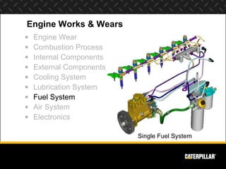
  • 1. Engine Works & Wears • Engine Wear • Combustion Process • Internal Components • External Components • Cooling System • Lubrication System • Fuel System • Air System • Electronics Single Fuel System
  • 2. Function of Fuel System • Meters the amount of fuel to achieve desired power • Regulates engine speed and timing sequence • Helps control emissions
  • 4. Types of Fuel Systems • Pump & Line • Unit Injection  Current Scroll Fuel System  MUI  New Scroll Fuel System  EUI  Sleeve Metering Fuel System (SMFS)  HEUI  Program Electronic Engine Controls (PEEC)  Common Rail (Single Fuel) 1973 1981 1983 1988E 1994 CSFS MUI NSFS UI HEUI Pre 1970 1970 1975 1980 1985 1990 1995 2000 2005 Timeline 1974 1987 2004 SMFS PEEC Rail
  • 5. Fuel Delivery - History • Pre-Combustion (PC) • Direct Injection (DI) Fuel Line Fuel Line Fuel Injector Electrical Wire Fuel Injector Mechanically Glow Plug Nozzle Controlled Fuel Injector Unit Injector Housing Assembly Pre-Combustion Piston Piston Heat Plug Pre-Combustion Direct Injection Direct Injection Pencil Style Unit Injector
  • 6. Sleeve Metering Fuel System Barrel Fill Port Plunger Sleeve Spill Port Filling Begin Continue End Injection Injection Injection
  • 7. Scroll Metering Fuel System • Pump & line governor • Few moving parts • Simple mechanical governor • Easy starting & service • More tolerant of dirt • Economical
  • 8. MUI System • A unit injector is positioned above each cylinder • A mechanically actuated governor controls fuel rate (scroll metered) with flyweights and springs • Timing is fixed
  • 9. EUI System • A unit injector is positioned above each cylinder • An Electronic Control Module (ECM) controls fuel rate and timing • Injectors are mechanically actuated by a camshaft
  • 10. EUI - Injector Fill • Without pressure from the rocker arm, a spring keeps the plunger retracted • Fuel flows into the injector through the fill / spill port, past the solenoid valve and into the barrel
  • 11. EUI - Injection • On a signal from the ECM, the solenoid closes the fuel valve • Pressure elevates at the tip to the 5,500 psi needed to unseat the valve • Injection begins
  • 12. EUI - Injection • Fuel continues to inject until the ECM signals the solenoid to open the valve • Injection timing and duration is controlled by the ECM
  • 13. HEUI System • A unit injector is positioned above each cylinder • An Electronic Control Module (ECM) controls fuel rate, timing, and injection pressure • The injector is hydraulically actuated
  • 14. Cat Fuel System – Single Fuel Fuel Manifold Pump C6.6 Injector
  • 15. Fuel System Wear & Failure Causes • Short unit injector life due to excessive abrasive particles in the fuel  Abrasive particles damage sealing surfaces causing leakage of high pressure fuel and low engine power  Abrasive particles are inherent in most fuels  Most particles can be removed by using High Efficiency filters • Injector seizure due to excess water in the fuel  Always small amounts of water in fuel, which is harmless  Excess water in fuel reduces the lubricating film strength of fuel and causes seizure of the injector plunger and barrel  Maximum amount of allowable water in fuel is 0.1%
  • 16. Fuel System Wear & Failure Causes • Injector sticking or seizure due to fuel overheating  Fuel in the injector “cooks” and produces varnish which causes components to stick or seize  Viscosity of hot fuel is inadequate and the fuel film thickness will not provide adequate protection against scuffing or seizure of the plunger and barrel  Fuel overheating can be caused by operating in extreme ambient temperatures. An auxiliary fuel cooler installed in the fuel supply line to the cylinder heads may be required to limit fuel temperatures  Running fuel tank too low, or running out of fuel causes the fuel to cycle through the engine too frequently and becomes very hot. This can be avoided by keeping the fuel tank levels at ¼ full or above
  • 17. Fuel System Wear & Failure Causes • Poor quality oil  Fuel may be low in viscosity or lubricity. Fuel which is old or oxidized often contains excessive gums or resins which promotes injector sticking or seizure.
  • 18.
  • 19. Effect of Work Environment • Dust • Temperature/Climate • Hours of continuous operation • Terrain
  • 20. System Improvement • Reduce system damage caused by fuel  Water Separator  Primary Fuel Filter  Bypass Flow • Minimize tip failure caused by aeration  Maintain fuel supply pressure
  • 21. Stripping Out Water • Water Separator  Second line of defense • All free water • 87% emulsified water  Injector damage
  • 22. Removing Larger Debris • Primary Fuel Filter  10+ micron particle retention • prevents premature secondary fuel filter plugging • protects fuel transfer pump
  • 23. Remove Fine Abrasives • Secondary Fuel Filter  2 micron and larger • 98% efficient  Reduces wear on fuel injectors and pumps • Essential for higher pressure systems • Extends life of older systems as well
  • 24. Double Filter/Double Life • Series filtration  Second filter “safety net” • Second filtering pass • Filter failure - Double injector wear life
  • 25. Engine Works & Wears • Engine Wear • Combustion Process • Internal Components • External Components • Cooling System • Lubrication System • Fuel System • Air System • Electronics
  • 26. Air Intake & Exhaust System Functions Boost air at 300 Inlet air from air º- 400º cleaners Inlet air from air cleaners Exhaust out Air manifold From exhaust ports at cylinder heads • Provide adequate quantities of clean • Compresses the filtered intake air intake air into the cylinders in order to • Removes exhaust gases from the product more power cylinders and reduces exhaust noise
  • 28. Air System Components • Precleaner • Air Filters • Filter Service Indicator • Turbochargers • Aftercooler • Intake & Exhaust Manifolds • Muffler
  • 29. Air System Operation • Flow 1. Precleaner 2. Air Filters 3. Turbocharger 4. Intake Manifold & Cylinder Head(s) 5. Combustion Chamber 6. Exhaust Manifold • Wear  Turbocharger • Bearings • Seals
  • 30. Air System Wear & Failure Causes • Single most common problem – dust ingestion  Causes accelerated abrasive wear of piston rings & liners  Most often caused by inlet leaks around flexible joints in air inlet piping  May also be caused by defective/damaged air filters, or poor maintenance practices • Plugged air filters • Turbo failures • Coolant to air leaks in the aftercooler • Hydraulic lock

Notas do Editor

  1. January 15, 2013 The fuel system is the most sophisticated, expensive and critical of all the engine systems. Engine performance, economy and durability depend on proper performance of the fuel system. Keeping fuel clean and using high quality, high efficient fuel filters will allow the fuel system components to perform properly until the engine reaches overhaul life. The single fuel system is also known as the common rail fuel system.
  2. January 15, 2013 The function of the fuel system is threefold. First, it meters the amount fuel that is injected into the combustion chamber to achieve the desired horsepower output for the engine. Second, the fuel system regulates the engine speed and the timing sequence of the engine. And thirdly, since higher injection pressures cause the fuel to burn more completely and lowers the emissions, the fuel system helps to control emissions.
  3. January 15, 2013 Supply fuel is drawn from the fuel tank, through the primary fuel filter and into the inlet port of the gear-type fuel transfer pump. Pressurized fuel flows from the outlet port of the fuel transfer pump through the engine ECM. The fuel provides cooling to the ECM to remove excess heat produced by the electronic components inside. Pressurized supply fuel flows from the ECM through the high efficiency secondary fuel filters to the fuel supply passages in each cylinder head, and to each injector. The volume of supply fuel flowing through the cylinder heads is about 3 to 4 times the amount being injected into the cylinder. The unneeded supply fuel flows past the injectors and removes some of the excess heat of combustion. Keeping the injectors cool is necessary to prevent fuel inside the injector nozzle from becoming so hot that it turns to asphaltines and causes the injector to fail.
  4. January 15, 2013
  5. January 15, 2013 It is important to understand some of the differences in fuel delivery that might be found in the field as the populations of Caterpillar engines are quite large. Since the 1960’s, there have been two methods of delivering fuel into the combustion chamber; the first is pre-combustion, where the fuel begins ignition in a pre-combustion chamber before going into the cylinder; and the second is direct injection, in which the fuel is injected directly into the cylinder for combustion. The pre-combustion chamber system is found on older engine models such as the D330 and D333 engines as well as some of the first 3304 & 3306 engines. Fuel is pulled from the tank by the fuel transfer pump and pumped through the primary and secondary fuel filters to the fuel injection pump housing where the individual fuel pumps are located. The fuel injection pumps force fuel through the high pressure lines to the fuel nozzles. A precision drilled hole in the end of each nozzle atomizes fuel as it enters the pre-combustion chamber. As the fuel begins to ignite, the heat of combustion forces the remaining fuel and air mixture through the orifice in the pre-combustion chamber into the cylinder. On direct injection engines, fuel travels from the tank through the filters, pump, and lines to the injector housing. However, instead of pre-igniting the fuel, direct injection engines inject fuel directly into the cylinder. You can tell pistons on DI engines because the top of the piston crown has a conical crater design and no steel heat plug. Each unit injector has a high pressure injection pump and injector nozzle built-in each unit assembly. There is one unit injector for each cylinder. Low pressure fuel is delivered from the fuel transfer pump to each unit injector.
  6. January 15, 2013 When the plunger and sleeve are in the filling position, the low pressure fuel can fill the pump through the low pressure fill port. When the cam moves the plunger up, the fill port is closed by the barrel. This is the point where the pressure starts to increase on the fuel. When the pressure is high enough to open the valve in the nozzle, the fuel is injected into the cylinder. The cam is still lifting the plunger higher. When the spill port opens above the sleeve, the injection stops because the pressure is released,
  7. January 15, 2013 The Cat 3406A was introduced in 1973 with the current scroll metering fuel system. Since then, a number of changes have been made to meet the demand for an even more reliable and economical engine, while meeting governmental regulations. The 3406B, released in 1983, included the new scroll metering fuel system. The new scroll metering fuel system had been in production since 1980 on the 3300 engines. This fuel system is a key factor in the emissions, performance and fuel economy improvements in the 3406B. In 1991, the fuel system was changed to incorporate a more aggressive fuel camshaft to improve emissions. In 1992, the 3406C was introduced and there were no changes to this mechanical fuel system. “ The simple operation of this compact unit provides reliability with easy maintenance.” A scroll or helix is the top half of the plunger. A simple slot takes the place of the vertical hole used before. As the plunger is rotated by the rack, a higher or lower part of the helix faces the supply port. Simple, but limited high performance capability. This schematic of the 3406B/C engine fuel system (NSFS). The transfer pump (5) pulls fuel from the fuel tank (1) through the supply shutoff valve (3) through the primary fuel filter (4) to the fuel transfer pump itself. The transfer pump then pressurizes the fuel and pushes it through the hand priming pump (7), into the secondary fuel filter (6) and into the fuel manifold (8) under moderate pressure. With moderate fuel pressure inside the fuel manifold and the void (vacuum) inside the high pressure pumps, the fuel is loaded into the cavity of the high pressure pump, the high pressure pump now meters a small amount of fuel and sends it through the high pressure fuel lines (9) and through the head adapter (10) to the injection nozzle (11) at a very high pressure. (2) = tank drain to remove water and sediment
  8. January 15, 2013
  9. January 15, 2013 The fuel is “atomized” into each cylinder by its own fuel injector.
  10. January 15, 2013 While the plunger is up out of the way, fuel can flow through the injector and eventually into the barrel to await a signal from the ECM.
  11. January 15, 2013 As the ECM tells the solenoid to close the fuel valve, pressure gets elevated by the rocker arm pressure on the plunger. This high pressure then unseats the valve so that injection can begin.
  12. January 15, 2013 The ECM will tell the solenoid when to open the “spill-port” valve; thereby relieving enough of the spring pressure to allow the fuel an easier way to escape. This lowered pressure then causes the strong spring in the barrel to overcome the lowered pressure to close its own valve; thus stopping the injection of the fuel.
  13. January 15, 2013 Point out where the pressurized oil is pressing down on the top of the barrel. This fuel system is currently used on the C7
  14. January 15, 2013 Replaces 3056E. Will be used on WL 924,928,938; TTL 953,963; TTT D5N; WTS 613C; Skidder 525C The Cat Fuel System used on the C6.6 ACERT is completely new. It has been designed at Caterpillar fuel systems in Pontiac Illinois and sets a new standard in fuel delivery and control. The Cat Fuel System is fully electronically controlled and has the capability of multiple injections for each combustion event. This capability gives the fuel system the ability to meet future emissions standards. Fuel is pressurized to injection pressure in a single, high pressure pump and directed to a manifold where it is available via fuel injection lines to the electronically controlled injectors. The ECM fires the injectors, using maps stored within its memory, choosing optimum injection quantity and timing for all operating conditions. This closed loop system constantly monitors the fuel injection requirements and adjusts the fuel system output accordingly. The fuel system can be flash programmed via CAT ET. Let’s take a look at some of the system components as used in the C6.6 ACERT. This computer drawing shows a general system layout for the Cat Fuel System used in the C6.6. Filtered fuel is pressurized to injection pressure by the high pressure pump, which can be seen in the bottom center of this drawing. Pressurized fuel is then routed to a fuel manifold via a steel pipe where it is available for each of the injectors. The fuel manifold can be seen in the upper right of this drawing. The fuel injectors are connected by steel pipes to the manifold and electronically opened and closed by the ECM, giving the ECM complete control over the injection event. Let’s take a closer look at some of the individual fuel system components. The fuel manifold is a high quality steel component, specially designed to withstand the high injection pressures required by modern fuel systems. Fuel injection pressures may be in the neighborhood of 160 MPa (more than 23,000 PSI) with this system. The manifold consists of a fuel inlet, fuel outlets for each cylinder, a high pressure relief valve and a pressure sensor. Naturally with such high pressures in the fuel system, extreme caution must be used when performing any service on the system. High pressure lines to be replaced any time one of the connector fittings is loosened. The pump responsible for generating the fuel pressure is driven off the front gear train and is roughly the same size, shape and location as a HEUI pump. Unlike the HEUI pump however, this pump pressurizes fuel and not oil. It’s a two plunger pump with the fuel transfer pump attached to the end. The transfer pump will be the only serviceable component. Here’s a shot of the fuel injector after it has been removed from the cylinder head. The single hold down clamp fits over the squared off midsection and is held to the head with a single bolt. The electrical connections for the control solenoid can be seen on the left hand side of this photo.
  15. January 15, 2013
  16. January 15, 2013
  17. January 15, 2013
  18. January 15, 2013 The amount of abrasive debris in the source fuel varies widely with geographic location and operating environment. This abrasive debris is what causes premature wearout and replacement of fuel system components. The amount of filtration required to remove this debris is dependent on the amount of contaminants in the tank. The ability of the low-pressure systems to remove abrasive particles down to 1 micron size, as well as excess water, determines the life of the unit injector. These abrasive particles are much smaller than the human eye is capable of seeing. How big is a micron? Typically, the human eye can see a dust particle… about one thousandth of an inch. A micron is 25 times smaller than a ten thousandth of an inch. As is pictured, a micron is not detectible without intense magnification. Where and how a customer stores or receives fuel can greatly impact the fuel system performance. Storing fuel in a dirty storage tank or in a place that is unprotected from the weather can result in bad fuel. Water is present in all fuel. Free water is what separates into a layer at the bottom of a storage tank. Dissolved water is held in solution and needs to be stripped out. Amounts of water up to 0.1% by volume are acceptable. Storing a container outdoors subjects it to temperature fluctuations. This results in a build up of condensation/water in the storage container. In many parts of the world, fuel contains very large amounts of water due to poor handling and storage practices from the point where the fuel is refined to the end user. Abrasives are present in all diesel fuel. The amount of abrasives found in a particular volume of fuel varies dramatically when comparing fuel sourced from North America or Western Europe versus fuel found in the rest of the world. Abrasive particles may also be present in storage containers. The amount of water and highly abrasive microscopic particles found in fuels varies widely throughout the world… but the fueling and working environment itself introduces contamination into the fuel system. All of these contamination sources contribute to fuel system deterioration…
  19. January 15, 2013 Where a machine operates is directly related to maintenance intervals and filter arrangements. If the machine operates in a dusty environment, the need for tank breathers is very critical. Operating 24 hours, 7 days a week in mines and quarries may require more complex, high efficiency filter systems. An on-highway truck may need a simple high efficiency filter system. There is no single perfect filtration arrangement for every application. Each fuel system solution must be optimized.
  20. January 15, 2013 As previously discussed, not all water in the fuel is free water and not all abrasives settle to the bottom of the fuel tank as sediment. We must remove the excess water and abrasive particles that are in suspension. Otherwise, the unit injector will wear out pre-maturely. We start by using a fuel/water separator. Soot in the fuel is another concern. Designing a fuel system that better controls fuel temperature at the injector will reduce sticking and damage to the tip. Introduction of air into the fuel system can cause tip failure. Aeration is often the result of “starving” the fuel system and causing vacuum induced air pockets. To avoid damage, we must sustain an appropriate fuel supply pressure. We will now describe how components and system design can improve performance…
  21. January 15, 2013 A fuel/water separator is designed to remove water that is suspended in the fuel. Emulsified water is sometimes visible in a fuel tank as a milky layer between the fuel and the water. This milky layer is a “water saturated” fuel. The water separator strips out the remaining free water in the fuel, as well as, up to 87% of the emulsified water. The filter in the fuel/water separator is designed to allow fuel to pass through, but not water. Water collects on the outside of the filter, beads up, and eventually travels down the length of the filter into the water collection bowl. Periodically, the water collection bowl at the bottom of the fuel/water separator should be visually inspected. If the bowl is half full, it must be drained before operating the engine. If the emulsified water is not stripped out of the fuel, the film strength of the fuel will break down. Metal to metal contact between the plunger and the barrel will result and the injector will fail prematurely. Injector plunger scuffing and seizure (as seen in the picture) is nearly always causes by excessive amounts of water in the fuel. Integral to the fuel/water separator is the primary fuel filter…
  22. January 15, 2013 The purpose of the primary fuel filter is to remove larger abrasives from the supply fuel. In past years, 150 micron filters were installed as primary fuel filter. These are virtually useless. This is more evident with the advent of higher pressure fuel systems. Nearly all fuel system debris is smaller than 50 microns. The fact that these coarse filters rarely plugged is because nearly all of the damaging abrasives passed through them. The same filter media that strips out the emulsified water also retains the majority of debris that is 10 microns and larger. By removing the larger debris, the secondary fuel filter does not plug as quickly and less debris flows through the fuel pump. The primary fuel filter extends service intervals and prevents pump deterioration.
  23. January 15, 2013 Higher injection pressures are required to meet emission standards. With the same amount of abrasives in the fuel, these higher pressures cause accelerated abrasive wear to injector components. In order to prevent abrasive wear, microscopic abrasive particles must be removed from the fuel. Critical wear components in unit injectors are already made of the hardest possible materials. Improving fuel filtration is the only way to reduce abrasive wear. The secondary fuel filter is designed to remove abrasive particles between two and ten microns. Caterpillar’s secondary fuel filter is better than 98% efficient in removing particles 2 microns and larger from the fuel stream. The 2 to 10 micron particles can erode metal quickly at today’s high fuel system pressures. By removing these particles, Caterpillar’s high efficiency fuel filter system can reduce wear on fuel injectors and pumps. High Efficiency 2 micron filters are required on all new Caterpillar high pressure fuel systems. Using the former 15 micron nominal will result in accelerated wear and shortened fuel system life.
  24. January 15, 2013 In applications where there are extremely high concentrations of small abrasives in the fuel, one filter may not provide enough protection. Vibration of engine mounted filters, continuous spill pulses from unit injectors and excessive pressure drop across the filter of more than 10 psi can force debris through the filter. In cases where severe wear has occurred, two filters in series are recommended to provide a second filtering pass. Without exception, this has proven effective in doubling or tripling injector life where severe wear exists.
  25. January 15, 2013 All diesel engines require a free supply of clean air to perform properly. The single largest contributor to premature engine wearout is dust ingestion through a poorly maintained air intake system. The amount of air filtration on an engine is determined by its intended application. As an example, engines in most mining applications require extensive filtration due to continuous operation in dusty environments.
  26. January 15, 2013 Diesel engines require large amounts of air in order to completely burn the fuel and perform properly. The air intake and exhaust system performs 3 functions which are critical to proper engine performance. Provides adequate quantities of clean filtered intake air Compresses the intake air into the cylinders in order to produce more power Removes exhaust gases from the cylinders and reduce exhaust noise
  27. January 15, 2013 This animation show the flow of air in an engine from the precleaner, through the air filters, through the turbo and aftercooler (if applicable), to the combustion chamber, then through the exhaust. It also explains what happens to the engine is there is a restriction in the air flow
  28. January 15, 2013 The major components of the Air System are: Precleaner -- The precleaner removes large particles of dirt and debris. Air Filters -- Usually there are two air filters, a primary and secondary filter. They collect contaminants and prevent dirt from entering the engine. Air Filter Service Indicator -- The indicator monitors restriction through the air filters. It is the most accurate method for determining when to change air filters. Every engine should have one. An interesting fact is that changing filters too often can actually do more harm than good - because dirt can so easily enter the engine during a filter change. This makes the indicator a very useful and important maintenance tool. Turbocharger -- Exhaust gases drive the turbocharger which pumps additional air into the engine allowing more fuel to be burned, thereby increasing the horsepower output. Aftercooler -- The aftercooler cools the air after it leaves the turbocharger but before it enters the engine. This increases the air density, so more air can be packed into each cylinder. Air Intake & Exhaust Manifolds -- The manifolds connect directly to the cylinder head(s). The intake manifold distributes clean air from the air filter or turbocharger into each cylinder, while the exhaust manifold collects exhaust gases from each cylinder and directs them to the turbocharger and/or to the muffler. Muffler -- the muffler reduces the sound level and provides sufficient back pressure to the engine, so the engine “breathes” as designed.
  29. January 15, 2013 1. Air first enters the system via the precleaner. Here large dirt particles are removed. 2. Then air moves through the primary and secondary air filters for further cleaning. On turbocharged engines the spinning of the turbocharger compressor wheel pulls air into the turbocharger. 3. The compressor wheel compresses the air (which also heats it) and sends it to the aftercooler. The aftercooler reduces the air temperature making it more dense so more air can be packed into the cylinders. 4. The dense compressed air moves from the aftercooler through the air intake manifold and cylinder head(s). 5. Past the intake valves into each cylinder combustion chamber. As the intake valves close, and the piston moves up in the cylinder, the air is compressed further. When the piston is near the top of its stroke, fuel is injected into the combustion chamber. The fuel mixes with the hot, compressed air and ignites. The force of the combustion pushes the piston down on the power stroke. 6. When the piston moves up again, it is on the exhaust stroke. The exhaust valves open allowing exhaust gases out through the exhaust manifold.
  30. January 15, 2013 Defects or problems in the air inlet and exhaust systems can cause accelerated abrasive wear or catastrophic damage to the core engine components. With the exception of aftercooler leaks, these causes are directly related to maintenance practices, and are avoidable. Proper machine operation and high quality maintenance can eliminate most causes of accelerated wear and failure related to the air inlet and exhaust system.