Manual de Recarga Samsung ML 1630 | SCX 4500
•
0 gostou•2,832 visualizações

Manual utilizado nos modelos Samsung SCX 4500 para Impressoras ML 1630.

Recomendados
Mais conteúdo relacionado
Mais procurados
Mais procurados (19)
Destaque
Destaque (11)
Semelhante a Manual de Recarga Samsung ML 1630 | SCX 4500
Semelhante a Manual de Recarga Samsung ML 1630 | SCX 4500 (17)
Mais de Valejet
Mais de Valejet (14)
Último
Último (20)
Manual de Recarga Samsung ML 1630 | SCX 4500
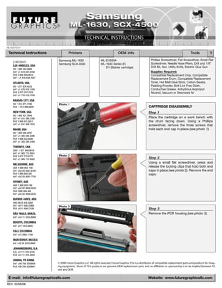
- 1. ML1630TECH Technical Instructions Printers OEM Info Tools 1 Samsung ML-1630 ML-D1630A Phillips Screwdriver, Flat Screwdriver, Small Flat CORPORATE Screwdriver, Needle Nose Pliers, Drill and 1/8” Samsung SCX-4500 ML-1630 Series (E) LOS ANGELES, USA Drill Bit, Awl, Utility Knife, Electric Glue Gun D1 (Starter cartridge) US 1 800 394.9900 Int’l +1 818 837.8100 Supplies Required: FAX 1 800 394.9910 Compatible Replacement Chip, Compatible Int’l +1 818 838.7047 Replacement Drum, Compatible Replacement ATLANTA, USA Toner, Hot Melt Glue Stick, Cotton Swabs, US 1 877 676.4223 Padding Powder, Soft Lint-Free Cloth, Int’l +1 678 919.1189 Conductive Grease, Anhydrous Isopropyl FAX 1 877 337.7976 Alcohol, Vacuum or Deionized Air Int’l +1 770 516.7794 KANSAS CITY, USA US 1 913 871.1700 Photo 1 FAX 1 913 888.0626 CARTRIDGE DISASSEMBLY NEW YORK, USA Step 1 US 1 800 431.7884 Int’l +1 631 588.7300 Place the cartridge on a work bench with FAX 1 800 431.8812 the drum facing down. Using a Phillips Int’l +1 631 588.7333 screwdriver, remove the three screws that MIAMI, USA hold each end cap in place (see photo 1). US 1 800 595.4297 Int’l +1 305 594.3396 FAX 1 800 522.8640 Int’l +1 305 594.3309 TORONTO, CAN CAN 1 877 848.0818 Int’l +1 905 712.9501 FAX 1 877 772.6773 Photo 2 Int’l +1 905 712.9502 Step 2 Using a small flat screwdriver, press and MELBOURNE, AUS AUS 1 800 003. 100 release the locking clips that hold both end Int’l +62 03 9561.8102 caps in place (see photo 2). Remove the end FAX 1 800 004.302 caps. Int’l +62 03 9561-7751 SYDNEY, AUS AUS 1 800 003.100 Int’l +62 02 9648.2630 FAX 1800 004.302 Int’l +62 02 9548.2635 BUENOS AIRES, ARG ARG 0810 444.2656 Int’l +011 4583.5900 Photo 3 FAX +011 4584.3100 Step 3 SÃO PAULO, BRAZIL Remove the PCR housing (see photo 3). Int’l +55 11 5524.8000 BOGOTÁ, COLOMBIA Int'l +57 1410.8842 CALI, COLOMBIA Int'l +57 2661.1166 MONTERREY, MEXICO Int' +52 55 5333.9800 JOHANNESBURG, S.A. S.A. +27 11 974.6155 FAX +27 11 974.3593 ZHUHAI, PR CHINA Int’l +86 756 3359608 © 2008 Future Graphics, LLC. All rights reserved. Future Graphics (FG) is a distributor of compatible replacement parts and products for imag- FAX +86 756 3359681 ing equipment. None of FG's products are genuine OEM replacement parts and no affiliation or sponsorship is to be implied between FG and any OEM. E-mail: info@futuregraphicsllc.com Website: www.futuregraphicsllc.com REV. 03/06/08
- 2. 2 SAMSUNG ML-1630/SCX-4500 Technical Instructions Photo 7 Step 6 Using a small flat screwdriver, press down on the clip that holds the developer roller Step 4 bearing end cap (see photo 7). Slide the drum axle out of the toner Remove the developer roller bearing end hopper axle holder on the drive gear cap (see photo 8). side (see photo 4). Separate the waste hopper unit from the toner hopper unit (see photo 5). Set the waste hopper aside, away from the light. Photo 8 Photo 4 Photo 5 Photo 9 Step 7 Carefully remove the developer roller by holding the metal drive shaft (see photo 9). Remove the developer roller drive gear. TONER HOPPER DISASSEMBLY Photo 10 Step 8 Step 5 Clean the developer roller with deionized air Using needle nose pliers, remove the and a dry lint-free cloth. doctor blade contact spring (see photo 6). Step 9 Using a Phillips screwdriver, remove the two screws that hold the doctor blade in place (see photo 10). Photo 6 Photo 11 Step 10 Clean the doctor blade, first using deionized air, then with a cotton swab and alcohol. Step 11 Using a flat screwdriver, carefully pry out the toner hopper fill plug (see photo 11). © 2008 Future Graphics, LLC. All rights reserved. Future Graphics (FG) is a distributor of compatible replacement parts and products for imaging equip- ment. None of FG's products are genuine OEM replacement parts and no affiliation or sponsorship is to be implied between FG and any OEM.
- 3. SAMSUNG ML-1630/SCX-4500 Technical Instructions 3 Photo 12 Step 12 Carefully remove the toner unit gears and set them aside. Step 17 NOTE: Take care not to damage or lose the supply roller shim (see photo 12). Apply a small amount of conductive grease on the developer roller shaft Step 13 and doctor blade where the doctor Clean the toner hopper using deionized air blade contact spring is seated (see or a vacuum. photo 17). NOTE: Inspect the retaining blade for any physical damage. If there is any damage, it must be replaced. Photo 17 Photo 13 TONER HOPPER ASSEMBLY Step 14 Set the doctor blade on the toner hopper and install the two screws that hold the doc- tor blade in place (see photo 13). Photo 14 Step 15 Install the developer roller drive gear on the developer roller (see photo 14). Step 18 Install the developer roller by holding the Install the doctor blade contact metal drive shaft (see photo 15). spring. The short bend wire has to make contact with the doctor blade and the long straight wire with the developer roller shaft (see photo 18). Photo 18 Photo 15 Photo 16 Step 16 Install the developer roller bearing end cap (see photo 16). © 2008 Future Graphics, LLC. All rights reserved. Future Graphics (FG) is a distributor of compatible replacement parts and products for imaging equip- ment. None of FG's products are genuine OEM replacement parts and no affiliation or sponsorship is to be implied between FG and any OEM.
- 4. 4 SAMSUNG ML-1630/SCX-4500 Technical Instructions Photo 21 Step 22 Using a Phillips screwdriver, remove the two screws that hold the wiper blade in place Step 19 (see photo 21). Remove the wiper blade. If Fill the toner hopper with toner. you plan to reuse the wiper blade, clean it Install the fill plug. with deionized air. Step 20 Reinstall the toner unit gears (see photo 19). Set the toner hopper Step 23 aside. Clean the waste hopper using deionized air or a vacuum. Inspect the recovery blade for Photo 22 any physical damage. If damaged, the Photo 19 recovery blade must be replaced. CHIP REPLACEMENT Step 24 Place the waste hopper on a work bench (see photo 22). Using an awl, mark the centers of the sonic welds that hold the chip cover (see photo 23). Photo 23 WASTE HOPPER DISASSEMBLY Step 21 Place the waste hopper on a work bench. Slide the drum axle out from the non-gear side of the drum (see photo 20). Remove the drum from the waste hopper. If you plan to reuse the OEM drum, clean it with a dry lint-free cloth. Place the drum in Photo 24 a protected area away from light. Step 25 Using a 1/8” drill bit, carefully drill into the sonic welds until the chip cover is able to be removed (see photo 24). Trim the scraps Photo 20 from the sonic welds of the waste hopper with a utility knife and remove the plastic residue from the chip cover and waste hop- per. Photo 25 Step 26 Replace the chip. Attach the chip cover to the waste hopper with a small amount of hot glue (see photo 25). © 2008 Future Graphics, LLC. All rights reserved. Future Graphics (FG) is a distributor of compatible replacement parts and products for imaging equip- ment. None of FG's products are genuine OEM replacement parts and no affiliation or sponsorship is to be implied between FG and any OEM.
- 5. SAMSUNG ML-1630/SCX-4500 Technical Instructions 5 Photo 26 WASTE HOPPER ASSEMBLY Step 27 Apply padding powder to the wiper blade. Step 31 Set the wiper blade into the waste hopper Clean the PCR with a dry lint-free and install the two screws that hold the cloth. wiper blade in place (see photo 26). Step 32 Install the PCR into the PCR saddles and snap them into working posi- tion. Make sure the PCR saddle springs Photo 27 are installed correctly within the Step 28 edge of the housing (see photo 31). Apply padding powder to the drum. Apply a small amount of conductive grease to the drum axle at the keyed end of the drum axle (see photo 27). Photo 31 Photo 28 Step 29 Install the drum into the waste hopper with the drum gear on the opposite side from the chip (see photo 28). Slide the drum axle into the gear end of the drum, the non-keyed end of the drum axle first (see photo 29). Photo 29 Photo 30 PCR HOUSING ASSEMBLY AND DISASSEMBLY Step 30 Lift the PCR with the PCR saddles, spread the saddles aside slightly and remove the PCR (see photo 30). © 2008 Future Graphics, LLC. All rights reserved. Future Graphics (FG) is a distributor of compatible replacement parts and products for imaging equip- ment. None of FG's products are genuine OEM replacement parts and no affiliation or sponsorship is to be implied between FG and any OEM.
- 6. 6 SAMSUNG ML-1630/SCX-4500 Technical Instructions Photo 34 Step 34 Install the PCR housing (see photo 34). CARTRIDGE ASSEMBLY Step 33 Place the toner and waste hopper sections on a work bench (see photo 32). Snap the drum axle ends into the axle holders of the toner hopper sec- tion (see photo 33). Photo 35 Step 35 Rotate the drum axle so that the keyed end Photo 32 will fit into the gear end cap (see photo 35). Photo 36 Step 36 Apply a small amount of conductive grease at the ends of PCR, the developer roller and Photo 33 the supply roller shafts on the contact end cap side of the cartridge (see photo 36). Step 37 Install the end caps and the screws that hold the end caps in place. NOTES © 2008 Future Graphics, LLC. All rights reserved. Future Graphics (FG) is a distributor of compatible replacement parts and products for imaging equip- ment. None of FG's products are genuine OEM replacement parts and no affiliation or sponsorship is to be implied between FG and any OEM. E-mail: info@futuregraphicsllc.com Website: www.futuregraphicsllc.com