Hp 1012
•
0 gostou•397 visualizações

The document provides technical instructions for replacing components in a HP1012 toner cartridge. It consists of 42 steps with accompanying photos detailing how to disassemble the cartridge, clean components, replace the drum, doctor blade, and other parts, and reassemble the cartridge. For cartridges without a fill plug, it provides additional instructions on using a hole saw to create a toner fill port. The instructions are intended to guide a technician through a full refurbishment of the HP1012 cartridge.

Recomendados
Mais conteúdo relacionado
Mais procurados
Mais procurados (17)
Destaque
Destaque (12)
Semelhante a Hp 1012
Semelhante a Hp 1012 (18)
Mais de Valejet
Mais de Valejet (10)
Hp 1012
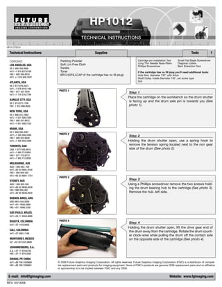
- 1. HP1012TECH Technical Instructions Supplies Tools 1 CORPORATE Padding Powder Cartridge pin installation Tool Small Flat Blade Screwdriver Soft Lint Free Cloth Long Thin Needle Nose Pliers Diagonal cutters LOS ANGELES, USA Phillips Screwdriver Bent Extraction Tool US 1 800 394.9900 Swabs Int’l +1 818 837.8100 Toner If the cartridge has no fill plug you’ll need additional tools: FAX 1 800 394.9910 BR1240FILLCAP (if the cartridge has no fill plug) Hole Saw, diameter 7/8”, with Arbor Int’l +1 818 838.7047 Shaft Collar, Inside Diameter 7/8”, set screw type ATLANTA, USA Drill US 1 877 676.4223 Int’l +1 678 919.1189 FAX 1 877 337.7976 PHOTO 1 Step 1 Int’l +1 770 516.7794 Place the cartridge on the workbench so the drum shutter KANSAS CITY, USA is facing up and the drum axle pin is towards you (See US 1 913 871.1700 FAX 1 913 888.0626 photo 1). NEW YORK, USA US 1 800 431.7884 Int’l +1 631 588.7300 FAX 1 800 431.8812 Int’l +1 631 588.7333 MIAMI, USA US 1 800 595.4297 Int’l +1 305 594.3396 PHOTO 2 Step 2 FAX 1 800 522.8640 Int’l +1 305 594.3309 Holding the drum shutter open, use a spring hook to TORONTO, CAN remove the tension spring located next to the non gear CAN 1 877 848.0818 side of the drum (See photo 2). Int’l +1 905 712.9501 FAX 1 877 772.6773 Int’l +1 905 712.9502 MELBOURNE, AUS AUS 1 800 003. 100 Int’l +62 03 9561.8102 FAX 1 800 004.302 Int’l +62 03 9561-7751 PHOTO 3 SYDNEY, AUS Step 3 AUS 1 800 003.100 Using a Phillips screwdriver remove the two screws hold- Int’l +62 02 9648.2630 ing the drum bearing hub to the cartridge (See photo 3). FAX 1800 004.302 Int’l +62 02 9548.2635 Remove the hub. left side. BUENOS AIRES, ARG ARG 0810 444.2656 Int’l +011 4583.5900 FAX +011 4584.3100 SÃO PAULO, BRAZIL Int’l +55 11 5524.8000 BOGOTÁ, COLOMBIA PHOTO 4 Step 4 Int'l +57 1410.8842 Holding the drum shutter open, lift the drive gear end of CALI, COLOMBIA the drum away from the cartridge. Rotate the drum count- Int'l +57 2661.1166 er clock-wise while pulling the drum off the contact axle MONTERREY, MEXICO on the opposite side of the cartridge (See photo 4). Int' +52 55 5333.9800 JOHANNESBURG, S.A. S.A. +27 11 974.6155 FAX +27 11 974.3593 ZHUHAI, PR CHINA Int’l +86 756 3359608 © 2008 Future Graphics Imaging Corporation. All rights reserved. Future Graphics Imaging Corporation (FGIC) is a distributor of compati- FAX +86 756 3359681 ble replacement parts and products for imaging equipment. None of FGIC's products are genuine OEM replacement parts and no affiliation or sponsorship is to be implied between FGIC and any OEM. E-mail: info@fgimaging.com Website: www.fgimaging.com REV. 03/16/06
- 2. 2 HP1012 Technical Instructions PHOTO 6 Step 6 With a bent extraction tool push the car- tridge pin out from the inside of the car- Step 5 tridge (See photo 6). Using needle nose pliers remove the PCR from the cartridge (See photo 5). Clean the PCR using a mild soap and water. PHOTO 5 PHOTO 7 Step 7 Using diagonal cutters pull the cartridge pins out from the both sides of the cartridge (See photos 7 & 8). Notes PHOTO 8 PHOTO 9 Step 8 Separate the two sections of the cartridge (See photo 9). Set the toner hopper aside. PHOTO 10 Step 9 Remove the drum shutter tension spring (See photo 10). © 2008 Future Graphics Imaging Corporation. All rights reserved. Future Graphics Imaging Corporation (FGIC) is a distributor of compatible replacement parts and products for imaging equip- ment. None of FGIC's products are genuine OEM replacement parts and no affiliation or sponsorship is to be implied between FGIC and any OEM.
- 3. HP1012 Technical Instructions 3 PHOTO 11 Step 10 Slide the drum shutter open and lift the shutter from its cradles (See photo 11). Step 16 Install the drum bearing hub onto the side of the cartridge. Install the two screws that hold the hub in place (See photo 16). PHOTO 16 PHOTO 12 Step 11 Using a Philips screwdriver remove the two screws holding the wiper blade (See photo 12). Remove the wiper blade. Step 12 Clean the waste hopper using dry com- pressed air or a vacuum. Clean the PCR saddle contact with alcohol and a swab. Step 17 PHOTO 13 Slide the drum shutter over the Step 13 waste hopper and place the shutter Apply padding powder to the used or new into its cradles (See photo 17). wiper blade. Install the blade onto the waste hopper and install the two screws that hold the blade in place (See photo 13). PHOTO 17 PHOTO 14 Step 14 Apply conductive grease to the PCR con- tact (black) saddle. Install the cleaned PCR into the saddles (See photo 14). PHOTO 15 Step 15 Apply padding powder to the drum. While rotating the drum counter clock-wise, slide the drum onto the contact axle (See photo 15). © 2008 Future Graphics Imaging Corporation. All rights reserved. Future Graphics Imaging Corporation (FGIC) is a distributor of compatible replacement parts and products for imaging equip- ment. None of FGIC's products are genuine OEM replacement parts and no affiliation or sponsorship is to be implied between FGIC and any OEM.
- 4. 4 HP1012 Technical Instructions PHOTO 20 Step 21 Remove the three gears from the side of the toner hopper, leaving the toner hopper Step 18 agitator gear (See photo 20). Reinstall the tension spring onto the drum shutter (See photo 18). PHOTO 18 PHOTO 21 Step 22 Rotate the cartridge 180°. Remove the screw holding the contact end cap to the toner hopper (See photo 21). Remove the end cap. Step 19 Set the waste hopper aside in a pro- tected area PHOTO 22 Step 20 Step 23 Remove the screw holding the gear Lift out the mag roller. Remove the mag end cap to the toner hopper (See roller bushings from the ends of the roller photo 19). Remove the end cap. (See photo 22). Step 24 Clean the mag roller first using dry com- pressed air or a vacuum. Then clean the PHOTO 19 roller using a lint free cloth and a mag roller cleaner. PHOTO 23 Step 25 Remove the two screws holding the doctor blade to the toner hopper (See photo 23). Remove the white scraper from the end of the blade, and remove the doctor blade. Clean the doctor blade using a lint free cloth and DI water. PHOTO 24 Step 26 Remove the doctor blade sealing end foams from both sides of the toner hopper (See photo 24). © 2008 Future Graphics Imaging Corporation. All rights reserved. Future Graphics Imaging Corporation (FGIC) is a distributor of compatible replacement parts and products for imaging equip- ment. None of FGIC's products are genuine OEM replacement parts and no affiliation or sponsorship is to be implied between FGIC and any OEM.
- 5. HP1012 Technical Instructions 5 PHOTO 25 Step 27 Using a small flat blade screwdriver push the seal exit port plug out from the hopper (See photo 25). Step 33 Install a new or a clean used doctor blade onto the hopper. Install the two white scrapers on the end of the doctor blade and install the two screws that hold the blade in place (See photo 30). PHOTO 26 Step 28 PHOTO 30 Clean the seal area using a swab and alco- hol. Step 29 Remove the backing of the seal and install the seal onto the toner hopper (See photo 26). PHOTO 27 Step 30 Step 34 Slide the tail of the seal through the seal Place the mag roller bushing on the exit port and install the plug in the end of the ends of the mag roller, the white hopper (See photo 27). bearing goes on the gear side and the black bearing goes on the con- tact side of the mag roller (See photo 31). PHOTO 31 PHOTO 28 Step 31 Remove the fill plug. Fill the toner hopper with toner (See photo 28). Reinstall the fill plug. NOTE: If the cartridge has no fill plug, please see Appendix A. PHOTO 29 Step 32 Install new doctor blade sealing end foams on both ends of the hopper (See photo 29). © 2008 Future Graphics Imaging Corporation. All rights reserved. Future Graphics Imaging Corporation (FGIC) is a distributor of compatible replacement parts and products for imaging equip- ment. None of FGIC's products are genuine OEM replacement parts and no affiliation or sponsorship is to be implied between FGIC and any OEM.
- 6. 6 HP1012 Technical Instructions PHOTO 34 Step 37 Place the toner hopper gear end cap on to the toner hopper install the screw that holds Step 35 the end cap in place. Install the mag roller onto the toner NOTE: The mag roller drive gear must sit hopper. Place the contact end cap correctly inside the end cap (See photo onto the side of the cartridge and 34). install the screw that holds the end cap in place. NOTE: Make sure the magnet sits correctly inside the contact end cap (See photo 32). PHOTO 35 Step 38 Apply a small bead of toner to the mag PHOTO 32 roller. Rotate the mag roller 4-5 revolutions. Step 39 Join the toner hopper and waste hopper together. Carefully slide the drum shutter open, install the cartridge pin on the contact side of the cartridge (See photo 35). PHOTO 36 Step 40 Using long thin needle nose pliers or a car- tridge pin installation tool, install the car- Step 36 tridge pin through the drum axle hub on the Install the three gears on the end of gear side of the cartridge (See photo 36). the toner hopper (See photo 33). PHOTO 33 PHOTO 37 Step 41 Install the cartridge tension spring next to the drum contact hub (See photo 37). Step 42 Test cartridge. © 2008 Future Graphics Imaging Corporation. All rights reserved. Future Graphics Imaging Corporation (FGIC) is a distributor of compatible replacement parts and products for imag- ing equipment. None of FGIC's products are genuine OEM replacement parts and no affiliation or sponsorship is to be implied between FGIC and any OEM.
- 7. In September 2003, HP released a new entry level laser printer, the HP1012. Based on a new Canon engine the HP1012 provides a few improvements over the discontinued HP1000. The biggest improvement being that the HP1012 can print at 15 pages per minute, an increase of 5 pages per minute compared to the HP1000. Like the HP1000, the HP1012 prints at a resolution of 600x600 dpi but also can support 1200 dpi using the HP FastRes 1200 technology. Targeted at small business users and home offices, the HP1012 has a starting price of just under $200. The machine uses a new all in one toner cartridge (Q2612A) that holds 110 grams of toner and yields 2,000 pages at 5% coverage. At a price of $69 the Q2612A HP1012 HP1012 cartridge holds less toner, prints less pages, and costs more than the HP1000 cartridge. Appendix A: Drill a hole through the molded plastic funnel, where the toner entry port has been located on the old style cartridges (Photo B). New style HP1012 cartridges do not have a toner entry port or a fill plug. Use a 7/8” Hole Saw to make a hole on the left (contact) side of the toner hopper, where the toner entry port has been located on the old style cartridges. Install set screw type Shaft Collar on the Hole Saw (Photo A). The distance between the working edge of the saw and the low edge of the collar should be 13 mm, to limit the drilling depth and prevent agitator damage. Clean the toner hopper with vacuum or compressed air. Fill the toner hopper with toner. Install BR1240FILLCAP (Photo C). Go to the Step 32 of the Technical Instructions. © 2008 Future Graphics Imaging Corporation. All rights reserved. Future Graphics Imaging Corporation (FGIC) is a distributor of compatible replacement parts and products for imag- ing equipment. None of FGIC's products are genuine OEM replacement parts and no affiliation or sponsorship is to be implied between FGIC and any OEM. E-mail: info@fgimaging.com Website: www.fgimaging.com