
Recomendados
Mais conteúdo relacionado
Último
Último (20)
Destaque
Destaque (20)
How to calculate your led heat sink
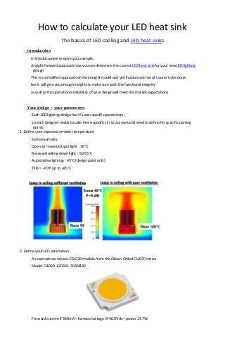
- 1. How to calculate your LED heat sink The basics of LED cooling and LED heat sinks Introduction In this document we give you a simple, straight forward approach how you can determine the correct LED heat sink for your new LED lighting design This is a simplified approach of the integral model and verification test has of course to be done, but it will give you enough insights to make sureboth the functionalintegrity as well as the operational reliability of your design will meet the market expectations Your design – your parameters Each LED lighting design has it’s own specific parameters, so each designer needs to take these specifics in to accountand need to define his specific starting points 1. Define your expected ambient temperature Someexamples: Open air mounted spotlight : 30°C Recessed ceiling down light : 50-55°C Automotive lighting : 45°C (design point only) Tlife = -40°C up to +85°C 2. Define your LED parameters As example we take a LED COBmodule fromthe Citizen Citiled CLL020 series Model CLL020-1203A1-303M1A2 Forward currentIf 360mA –forward voltageVf 40.9Vdc –power 14.7W
- 2. Luminous flux 1210lm –CCT 3000K Maximum casetemperature Tc 100°C - Maximum junction temperature Tj 150°C Thermal resistanceof the COB module Rj-c 2.6°C/W Citizen guarantees for this module a 50.000hrlifetime (conditional, 70% of remaining flux) MostLED COB module manufacturers justprovidelifetime expectations under ideal conditions, like 25°C ambient temperature We calculate with 90% reliability on these for the maximum junction temperature we want in our design – example below If a B10,L70 curveis available, we suggestyou determine your required lifetime and read out the maximum junction temperature Tj related In this case we wantto keep our junction temperature below 90% of the Tj max => Tj required < 150°C x 90% < 135°C 3. Calculate the required LED heat sink The basics to do that is to understand the scheme at the rightEach part of the design adds up some heat due to individual thermal resistances of each material – the adding up can be calculated as T = Pd x Rth In this case we havethe thermal resistanceof the Citizen LED COB module (Rj-c), the thermal resistance of a gap filler (thermal pad or grease) we want to place between the COB module and the heat sink (Rb), and the thermal resistancefromour heat sink (Rh) which has to make that the total design stays below the maximum required junction temperature Tj
- 3. If our led light is in a recessed environmentI want to calculate with an ambient temperature Ta of 45°C Means the maximum temperature added in the total design is Tj – Ta = 135°C – 45°C = 90°C The total power to dissipateis of courselower than the total power the LED consumes Some part of the power becomes light – the moreefficient your LED module, the bigger partof the total power will be transferred in to light, easy to verify if you compare the luminous flux to the power As a fist rule we use80% of the total power to be dissipated (Pd) Pd = 14.7W x80% = 11.76W Now we justdefine mathematically whatwould be the maximum thermal resistanceour heat sink should have, or define the maximum raise in temperature our heat sink will create when dissipating Pd 11.76W Supposewe will use a phasechange gap filler thickness 0.18mm(thermalpad which becomes fluid on firstheating cycle) with a thermal resistanceof 0.4°C/W Let’s see what weknow already and what is missing Only thing missing now is the needed thermal resistanceof the heat sink Rh
- 4. Choose a heat sink with an Rth value of < 4.65°C OR (see notes below) Choose a heat sink which guarantees less than (99.7°C – 45°C) = 54.7°C heating at a dissipated power Pd of 11.76W 4. Verify the design After applying the thermal pad and the heat sink, verify the design SomeLED COB module manufacturers foreseea thermal measurementpoint at the case Remember for this Citizen COBmodule Tc measurementmax was 100°C Since we designed with some safety margins you should measurea temperature around 87-92°C 5. Importantremarks -Somemanufacturers givea single thermal resistance value Rth for the heat sink, independent on ambient temperature and power to dissipate Please be awarethe Rth of the same heat sink will not be equal under all conditions -The approach made in this documents don’t take in effect that the heat spreading will become more and more difficult with the COB modules becoming smaller and smaller A COB LED module of 20x20mmfor 20W or a COB LED module of 40x40mmfor 20W can have a total different heat conduction towards the heat sink End of document