
Recomendados
Mais conteúdo relacionado
Mais procurados
Mais procurados (20)
Semelhante a Elect principles -_ac_circuits_year1
Semelhante a Elect principles -_ac_circuits_year1 (20)
Mais de sdacey
Mais de sdacey (15)
Último
Último (20)
Elect principles -_ac_circuits_year1
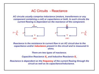
- 1. AC Circuits - Reactance AC circuits usually comprise inductance (motors, transformers or any component containing a coil) or capacitance or both. In such circuits the current flowing is dependant on the reactance of the component. I V (AC) C I V (AC) L Reactance is the resistance to current flow in an AC circuit due to the capacitance and/or inductance present in the circuit and is measured in ohms. There are two types of reactance; Capacitive Reactance XC and Inductive Reactance XL. Reactance is dependent on the frequency of the current flowing through the circuit as well as its capacitance/inductance. I = V XL I = V XC
- 2. AC Circuits - Reactance Inductive Reactance XL = 2πfL where f is the supply frequency in Hertz. and L is the inductance of the circuit in Henry’s Capacitive Reactance where f is the supply frequency in Hertz. and C is the capacitance of the circuit in Farad’s In each case the unit of reactance is the Ohm. AC circuits with purely resistive elements do not have reactance and can be treated using Ohm’s law. XC = 1 2πfC
- 3. AC Circuits - Reactance Activity Inductive (XL ) 1. Calculate the inductive reactance of a coil having an inductance of 150mH when connected to a 50Hz. supply. If the supply voltage is 230 V determine the current flowing. 2. Calculate the inductive reactance and current flowing if the supply frequency is doubled to 100Hz. Capacitive (XC ) 3. Calculate the capacitive reactance of a 470µF capacitor when connected to a 50Hz. supply. If the supply voltage is 230 V determine the current flowing. 4. Calculate the capacitive reactance and current flowing if the supply frequency is doubled to 100Hz.
- 4. AC Circuits – Phase Angle When an alternating current flows in a circuit containing reactance the current is no longer in step (phase) with the applied voltage. In an inductive circuit this is due to the magnetic effects causing opposition to the current flow. In capacitive circuits this is due to the electrostatic effects within the dielectric material. This effect is known as the circuit ‘phase angle’ and is used to represent the angle between applied voltage and the current flowing in the circuit. VC IC Current leading voltage by 90° (capacitive) Current lagging voltage by 90° (inductive) VL IL IR VR Current in step with voltage (resistive)
- 5. AC Circuits – The Phasor Diagram It is common practice to identify quantities in an electric circuit by use of vectors (phasor diagrams). As with force vectors, phasor’s are drawn to scale. The length of the phasor represents the magnitude of the quantity and the angle represents the circuit phase angle between the quantities. i Pure Capacitance v i Pure Resistance v In purely resistive circuits the phase angle is zero. The current is ‘in-step’ with the applied emf. i Pure Inductance v In purely inductive circuits the phase angle is 90° ‘lagging’. The current is behind the applied emf by 90° In purely capacitive circuits the phase angle is 90° ‘leading’. The current is ahead of the applied emf by 90° “CIVIL”
- 6. AC Circuits - The Phasor Diagram - Resistive Load It is common practice to identify quantities in an electric circuit by use of vectors (phasor diagrams). As with force vectors, phasor’s are drawn to scale. The length of the phasor represents the magnitude of the quantity and the angle represents the circuit phase angle between the quantities. Pure Resistance In purely resistive circuits the phase angle is 0°. The current is ‘in step’ with the applied emf. v i -1.5 -1 -0.5 0 0.5 1 1.5 0 40 80 120 160 200 240 280 320 360
- 7. AC Circuits – The Phasor Diagram – Capacitive Load It is common practice to identify quantities in an electric circuit by use of vectors (phasor diagrams). As with force vectors, phasor’s are drawn to scale. The length of the phasor represents the magnitude of the quantity and the angle represents the circuit phase angle between the quantities. In purely capacitive circuits the phase angle is 90° ‘leading’. The current is ahead of the applied emf by 90° i Pure Capacitance v -1.5 -1 -0.5 0 0.5 1 1.5 0 40 80 120 160 200 240 280 320 360 90°
- 8. AC Circuits – The Phasor Diagram – Inductive Load It is common practice to identify quantities in an electric circuit by use of vectors (phasor diagrams). As with force vectors, phasor’s are drawn to scale. The length of the phasor represents the magnitude of the quantity and the angle represents the circuit phase angle between the quantities. -1.5 -1 -0.5 0 0.5 1 1.5 0 40 80 120 160 200 240 280 320 360 In purely inductive circuits the phase angle is 90° ‘lagging’. The current is behind the applied emf by 90° Pure Inductance i v 90°
- 9. AC Circuits – Phasor Diagrams Activity 1. Draw the phasor diagram for a purely inductive electrical system having a supply voltage of 50 volts and a current of 20 amps. 2. Draw the phasor diagram for a purely capacitive electrical system having a supply voltage for 25 volts and a current of 10 amps flowing. 3. Draw the phasor diagram for a purely resistive circuit operating from a supply voltage of 100 volts with a load resistance of 20 ohms. In each case sketch the waveforms you would expect from the phasor diagrams and label the circuit phase angle and amplitude.
- 10. AC Circuits – What did we learn • Most AC circuits contain ‘reactance’. • There are two forms of reactance ‘Inductive (XL )’ and ‘capacitive (XC )’. • Reactance has units of Ohms. • Circuits containing pure inductance or pure capacitance cause the current to be out of phase (phase angle) with the applied emf by 90º. • Capacitive circuits cause the current to ‘lead’ the voltage. • Inductive circuits cause the current ‘lag’ the voltage. • Alternating quantities can be represented by ‘phasor diagrams’.