

Recomendados
Mais conteúdo relacionado
Semelhante a Cif l26
Semelhante a Cif l26 (20)
Último
Último (20)
Cif l26
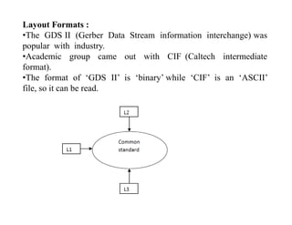
- 1. Layout Formats : •The GDS II (Gerber Data Stream information interchange) was popular with industry. •Academic group came out with CIF (Caltech intermediate format).o ). •The format of ‘GDS II’ is ‘binary’ while ‘CIF’ is an ‘ASCII’ file, so it can be read.
- 2. Other formats: OASISOASIS •Open Artwork System Interchange Standard •The OASIS is a trademark of the Semiconductor Equipment and Materials Institute (SEMI). DXF •Drawing Exchange format
- 3. Benefits of using CIF : •Standard machine-readable representation. h f b d f ifi / d i h•Other forms can be constructed for specific o/p devices such as: Plotters,, Video displays Pattern-generation machines. •Graphical layout language supports•Graphical-layout-language, supports Boxes, Polygon, Ci lCircle •Human readable/simple. •Unambiguous, machine readable syntax & semantics, Alsog , y , supports comments. •Captures layer information. •ASCII text fileASCII text file. •Exchanges design.
- 4. Boxes: Box length 25 width 60 center 80,40 Direction -20,20; OR B25 60 80 40 -20 20;
- 5. Polygons: Polygon A 0,0 B 10,20 C -30,40; OR P 0 0 10 20 -30 40; The edge connecting the last vertex with the first is implied.The edge connecting the last vertex with the first is implied.
- 6. Flashes: Round Flash Diam 200 center - 500 ,800 ; OR R 200 -500 800 ;
- 7. Wires: Wire width 10 A 0,0 B 10,20 c -30,40 ;Wire width 10 A 0,0 B 10,20 c 30,40 ; OR W 10 0 0 10 20 -30 40 ;
- 8. Layer Specification: L ND Diff iLayer ND nmos Diffusion ; OR LND ; (layer Technology)( y gy) ND nmos Diffusion; NP nmos Poly-silicon; NC nmos Contact cut; NM nmos Metal; NI nmos Depletion mode implant; iNB nmos Buried contact; NG nmos Over-glass opening;
- 9. Symbols: •A symbols is defined by proceeding the symbol geometry with they y p g y g y DS command and following it with the DF command. •Symbol definition may not nest, i.e. after a DS command is specified, the terminating DF must come before the next DS .specified, the terminating DF must come before the next DS . Definition start # 57 A/B = 100/1;e t o sta t # 5 / 00/ ; …..; Definition finish ; OR DS 57 100 1; ....….; DF;
- 10. e.g. (scaling 2000 CIF unit = 1 micron ); DS 1 100 1; L ND; B 25 60 80 40 -20 20; ( 25* 100/1 2500 i 1 25 i )( 25* 100/1 =2500 CIF units = 1.25 micron); P ----; L NP;L NP; P 0 0 10 20 -30 40; B ---- L NM; W 50 0 0 10 20 -30 40; B ---- DF;
- 11. Calling symbols : DS 2 100 1; LNM; R 6 20 0; C 1 T 45 13; (call symbol & transform); LNM; (This layer setting is not necessary. Layer settings are preserved across symbol callssettings are preserved across symbol calls and definitions.); R 3 0 0; DF;
- 12. Syntax : # i iCall symbol # 57 mirrored in x rotated to -1 ,1 then translated to 10 , 20 ; OROR C 57 MX R -1 1 T 10 20 ; The primitive transformations are : •MX :Mirror in x •MY Mi i•MY : Mirror in y •T point or T x, y •R point or R x, y
- 13. The primitive transformations are : •MX :Mirror in x •MY : Mirror in y •T point or T x, y: Translate the current symbol origin to this pointcu e sy bo o g o s po e.g. T 2 0
- 14. •R point or R x, y: Rotate symbol’s x axis to this directionsymbol s x-axis to this direction. e.g. R 1 1
- 15. Transformations: T = T1 .T2 .T3
- 16. Find primitive transformation matrix R(1,1) ?
- 18. Deleting Symbol Definition: Delete Definitions greater than or equal to 10; OR DD 10DD 10; •Symbol with indices greater than or equal to the argument to DD can be “ forgotten ” . •This will allow simultaneous processing of several CIF files appended in single CIF file .appended in single CIF file . •Euro Practice IC service : Low cost ASIC prototyping .
- 19. ( Definition of library symbols 0 to 99 ); DS 0 100 1 ; . (project 2) ; (second projects symbol definitions); . DF ; DS 1 100 1 ; DS 100 100 1 ; . . . . DF ; (project 1 ) ; DF ; DS 113 100 1 ; (second projects main symbol); C 1 T 3 45 ;(project 1 ) ; (first project symbol definitions); DS 100 100 1 ; C 57 T 45 13 ; C 1 T ‐3 45 ; DF ; E . DF ; DS 109 100 1 ; ( End of file) DS 109 100 1 ; (first project main symbol. Hierarchical mask layout data); . DF ; DD 100 ; (preserve only symbols 1 to 99);
- 20. Open Artwork System Interchange Standard (OASIS): •OASIS is a specification for hierarchical integrated circuit mask layout data format for interchange between EDA software, IC mask writing tools and mask inspection toolswriting tools and mask inspection tools. •Like GDSII, OASIS™ is a hardware- and software-independent bi d fbinary data format. •It delivers the following improvements over GDSII:g p An average of 10-50 times smaller file sizes Support of 64-bit arithmetic Unlimited design layersUnlimited design layers Richer data format for exchange of information between design and manufacturing stages.