SlideShare uma empresa Scribd logo
1 de 124
Baixar para ler offline
The Meadow F7 Board
A great board for .NET developers
ESP32 Doorbell
via Telegram
“The UPS Man
Always Rings Once”
Andonstar AD407 Analogue Electronics Design BASIC for the ESP32 and ESP8266 Developer’s Zone The Elektor ‘Intelekt’
Chess Computer (1981) The Elektor LoRa Node The Enviro+ RPi-HAT ESP32 Doorbell via Telegram Europe’s Most Successful
Start-up Accelerator? Hexadoku Homebrew PC for the Electronics Lab How-To: Calculate the PSCC Joy-IT DMSO2D72 Portable
3-in-1 Oscilloscope Lab, Sweet Lab Locating Wayward Wires The Meadow F7 Board My First LoRaWAN … and more
lektorSHAREDESIGN SELL ELECTRONICS
magazine
SELL
ESP32 DoorbellESP32 Doorbell
SHAREDESIGN
The Elektor
LoRa Node
Versatile, long-range, 868-MHz remote control
with state feedback and STM32 Inside
8-Page Supplement:Start-ups atproductronicaFast Forward 2019
Edition 2/2020 | March & April | www.elektormagazine.com
Edition2/2020–March&April2020
190356-B Cover 02-2020 EN.indd 1190356-B Cover 02-2020 EN.indd 1 06/02/2020 14:1006/02/2020 14:10
C
M
Y
CM
MY
CY
CMY
K
Untitled-4 1Untitled-4 1 06/02/2020 09:2106/02/2020 09:21
www.elektormagazine.com March & April 2020 3
In last November’s issue I hinted at our laboratory working on projects using
the LoRa radio protocol. This protocol allows data to be transmitted over
wide distances in a highly energy-efficient way. In the present issue you will
find two introductions to this exciting technology. The Elektor LoRa Node is a
flexible and configurable module that enables you to render your own projects
“LoRa compatible“. As an example application - also suitable of course for full
replication - we developed a remote control capable of switching an electric
appliance over distances of several hundred meters, with feedback on the
sender. As befits LoRa, such a node can be operated autonomously in the field
(using Li-Ion cells).
If you are keen to send sensor data to the Internet for access and use any-
where in the world you should take a look at the article My First LoRaWAN.
Here we describe how to connect a board to the open “The Things Network“
with minimal effort. You can either use an existing gateway in your area, or
install your own inexpensive gateway which receives the sensor data over
LoRa.
Of course there are many more intriguing developments in the world of
microcontrollers. One of them is Artificial Intelligence, and you can count on
my colleagues and me to discover some innovations at the Embedded World
exhibition, which we will report on later this year. Already available in our
online store is the MAix BiT Kit that permits entry-level explorations into the
fields of speech and image recognition, all programmable through the comfy
Arduino IDE! More about it in the next issues and of course up-to-date at
www.elektormagazine.com!
Jens Nickel
International Editor-in-Chief, Elektor Magazine
Data Transmission
with Ease
The Circuit
International Editor-in-Chief: Jens Nickel
Editor-in-Chief, English edition: Jan Buiting
Membership Manager: Denise Bodrone
International Editorial Staff: Eric Bogers, Rolf Gerstendorf, Denis Meyer,
Dr Thomas Scherer, Clemens Valens
Laboratory Staff: Mathias Claussen, Ton Giesberts,
Luc Lemmens, Clemens Valens, Jan Visser
Graphic Design & Prepress: Giel Dols
Publisher: Don Akkermans
Elektor Magazine,
English edition
Edition 2/2020
Volume 46, No. 500
March & April 2020
ISSN 1757-0875 (UK / US / ROW distribution)
www.elektor.com
www.elektormagazine.com
Elektor Magazine, English edition
is published 6 times a year by
Elektor International Media
78 York Street
London W1H 1DP
United Kingdom
Phone: (+44) (0)20 7692 8344
Head Office:
Elektor International Media b.v.
PO Box 11
NL-6114-ZG Susteren
The Netherlands
Phone: (+31) 46 4389444
Memberships:
Please use London address
E-mail: service@elektor.com
www.elektor.com/memberships
Advertising & Sponsoring:
Margriet Debeij
Phone: +49 170 5505 396
E-mail: margriet.debeij@elektor.com
www.elektor.com/advertising
Advertising rates and terms available on
request.
Copyright Notice
The circuits described in this magazine are for domes-
tic and educational use only. All drawings, photographs,
printed circuit board layouts, programmed integrated
circuits, disks, CD-ROMs, DVDs, software carriers, and
article texts published in our books and magazines
(other than third-party advertisements) are copyright
Elektor International Media b.v. and may not be repro-
duced or transmitted in any form or by any means,
including photocopying, scanning and recording, in
whole or in part without prior written permission from
the Publisher. Such written permission must also be
obtained before any part of this publication is stored
in a retrieval system of any nature. Patent protection
may exist in respect of circuits, devices, components
etc. described in this magazine. The Publisher does
not accept responsibility for failing to identify such
patent(s) or other protection. The Publisher disclaims
any responsibility for the safe and proper function
of reader-assembled projects based upon or from
schematics, descriptions or information published in or
in relation with Elektor magazine.
© Elektor International Media b.v. 2020
Printed in the Netherlands
190364-B EN colophon_editorial.indd 3190364-B EN colophon_editorial.indd 3 06/02/2020 08:3006/02/2020 08:30
4 March & April 2020 www.elektormagazine.com
This Edition
No. 500
Volume 47 – Edition 2/2020
March & April 2020
Features
Interview with
Wienke Giezeman,
Initiator of
The Things Network
45 electronica Fast Forward 2020
Sign up for the Start-up Platform Powered
by Elektor
46 “A Strong Supporter of Open Internet”
Interview with Wienke Giezeman,
initiator of The Things Network
49 The Meadow F7 Board
A great board for .NET developers
67 Raspberry Pi
Bash Command Cheat Sheet
68 Europe’s Most Successful
Start-up Accelerator?
HighTechXL, Eindhoven, The Netherlands
This Edition
Volume 47 – Edition 2/2020
March & April 2020
This Edition
Volume 47 – Edition 2/2020
March & April 2020
6
ESP32 Doorbell
via Telegram
“The UPS Man
Always Rings Once” 29
Regulars
16 Interactive
Corrections & Updates || Questions &
Answers
18 Analogue Electronics Design
Case Study #1 — Section 2: Preamplifier
optimized for MEMS microphone
34 Small Circuits Revival
Capita Selecta from the Elektor Project
Suggestions Box
74 Steeped in Electronics
Ordering components from Ukraine and
Russia
78 Lab, Sweet Lab
A glimpse of The Holy Place —
no unauthorized entry
84 How-To: Calculate the Prospective Short-
Circuit Current or PSCC
and choose the proper circuit breaker
87 Peculiar Parts, the series
TMS1000 Series Microcontrollers
88 Starting Out in Electronics (2)
Easier than imagined!
90 Developer’s Zone
Tips & Tricks, Best Practices and Other
Useful Information
104 Retronics: The Elektor ‘Intelekt’ Chess
Computer (1981)
Tiny Chess 86 ported to the Intel 8088
110 Beyond Electronics
PCB Art — Pushing the Limits of Industrial
Manufacturing
120 Elektor Store
what’s available @ www.elektor.com
122 Hexadoku
The original Elektorized Sudoku
190365-B EN Contents_Preview.indd 4190365-B EN Contents_Preview.indd 4 06/02/2020 08:3406/02/2020 08:34
www.elektormagazine.com March & April 2020 5
Projects
Next Edition
Elektor Magazine 3/2020
Weather Station 2020 • Experiments with AI • Nixie
Bargraph Thermometer 2.0 • Visualizing Sigfox Data •
E-Scooter Dismantled • Balancing Robot with Arduino
• Basic for ESP32: Applications • Triac Meets ATmega •
FreeRTOS and ESP32: Timers • Single-Chip ARM A7 and
M4 • Retronics • Small Circuits Revival • and more.
Elektor Magazine edition 3/2020 covering May & June 2020 is published
around 7 May 2020. Delivery of printed copies to Elektor Gold Members is
subject to transport. Contents and articles subject to change.
6 The Elektor LoRa Node
Versatile, long-range, 868-MHz remote
control with state feedback and STM32 Inside
21 My IoT Button: A Button for the Web
Part 1: IoT architecture
26 BASIC for the ESP32 and ESP8266
Programming with Annex WiFi RDS
29 ESP32 Doorbell via Telegram
“The UPS Man Always Rings Once”
36 My First LoRaWAN
With Blue Pill, LoRa Breakout Board and
The Things Network
54 Practical ESP32 Multitasking (2)
Task priorities
60 Sigfox and the IoT (3)
First steps on the network
80 Optical Probe for Oscilloscopes
Measure brightness fluctuations of lighting
systems
82 The ’TABULA’ Project — An Update
Tangibles with user feedback
93 Locating Wayward Wires
Track and trace concealed and defective
cables with ease and certainty
100 Homebrew PC for the Electronics Lab
Tips on component choice and construction
46n,
lektorSHAREDESIGN SELL ELECTRONICS
The Elektor
LoRa NodeLoRa Node
Versatile, long-range,
868-MHz remote control
with state feedback
and STM32 Inside
The
Meadow F7
Board
A great board for .NET developersA great board for .NET developers
49
71 Review: The Enviro+ RPi-HAT
Measure air quality with a Raspberry Pi and
the Enviro+ HAT
76 Review: Andonstar AD407
Better than its predecessor?
98 Review: Joy-IT DMSO2D72 Portable 3-in-
1 Oscilloscope
productronica 2019 Start-up Guide
(8-Page Supplement)
112 Distrelec - Powering the Future
Education is the foundation for
innovation, and innovation needs
advocates.
114 They’re All Winners!
Start-ups @ productronica 2019
117 Fast Forward Award Finals
The FFA 2019 Jury report
118 FFA 2019 Sponsors
Weller / Kurtz Ersa / Berstein / Almit
190365-B EN Contents_Preview.indd 5190365-B EN Contents_Preview.indd 5 06/02/2020 08:3406/02/2020 08:34
6 March & April 2020 www.elektormagazine.com
The Elektor LoRa Node
Versatile, long-range, 868-MHz remote control withVersatile, long-range, 868-MHz remote control with
state feedback and STM32 Insidestate feedback and STM32 Inside
PROJECTLABS
180666 EN The Elektor LoRa Node.indd 6180666 EN The Elektor LoRa Node.indd 6 06/02/2020 08:3706/02/2020 08:37
www.elektormagazine.com March & April 2020 7
the LoRaWAN Node Experimental
Platform, stuffed for ‘local’ LoRa
only.
• LoRa Button. Board no. 180666-2.
Two required for this project.
• LoRa AC Power Switch. Board no.
180666-1.
Together the three elements form not
only a remote control with a range of
10 to 20 times that of a consumer-level
WiFi link on 2.4 GHz, but also a LoRa
development platform with potential
for LoRaWAN. We kick off with the main
consumption, and size.
Read here how we did it. The story that
follows is kind of chronological, since with
this project we like to share not just the
final product and a quality write-up, but
also the real-life problems we ran into,
and the tools used to develop the project.
We do so at the request of many readers.
What’s being described
In this article we cover the three
elements mentioned above:
• LoRa Node. Board no. 180516-1,
The Elektor LoRa Node was born from the
idea to have a compact PCB with support
for rechargeable as well as non-recharge-
able batteries, a common microcontroller
like the LQFP48-cased STM32, and a type
RFM95 LoRa module, also, the PCB was
to fit in an enclosure that’s easily sourced
from one of the bigger distributors, also,
for the STM32 compiler, we… STOP!
As the enclosure will co-determine the
space available or the energy source, we
need to discuss this first. The initial idea
was to power the device from non-re-
chargeable batteries. This was rejected
since Elektor wants its contribution to
battery waste to be as small as possible.
So, a rechargeable battery solution was
sought, as well as ease of replacement
by the user. This would result in a small,
serviceable, water-resistant node capable
of operating not only in Elektor Labs’
comfy conditions, but also “out there in
the wild” and conveying real-life environ-
mental data. Further design aspects
heavily debated during the project devel-
opment period were the battery lifetime
and the sensors to accommodate on
or off the board. Clearly, we aimed to
have a flexible and useful platform to
explore LoRa and potentially LoRaWAN,
not for ‘academic’ use in the airco’d and
carpeted lab but ready to use in any
(rough) place out there for the purpose
of remote device on/off switching. From
here, the challenge is the ‘squaring of
the circle’ in terms of flexibility, power
By Mathias Clauβen and Luc Lemmens (Elektor Labs)
Convinced of the combined power of open-source hardware and
software, Elektor smashes the myth that LoRa is for pros only. This
article not only tells the story of persistence in electronics design in
the face of real challenges, but also of a 3-element LoRa Node you
can easily replicate for reliable on/off control with status feedback and
covering distances 10 to 20 times those of consumer-level WiFi and
433-MHz ISM LPR.
PROJECT DECODER
LoRa
intermediate levelÆ
entry level
expert level
4 hours approx.
€150 approx. excl. cases
USB UART,
Arduino IDE,
lab tool set
Arduino
STM32
Quick Features
Lora Node
• LoRaWAN Experimental Platform board with minimum parts stuffed
• Li-Ion battery powered
• User changeable cells
• STM32F072C8T6TR ARM Cortex-M0 MCU
• SPI F-RAM or Flash (optional)
• Crypto co-processor (optional)
• GPS module (optional)
• USB interface (optional)
LoRa AC Switch (slave device)
• Relay state feedback to Node central
• Switch contacts rated 5 A (1000 W at 230 VAC; (500 W at 115 VAC)
LoRa Button (master device)
• Low-energy design
• Optional OLED display
• Integral helical coil antenna
• 100–500 m range to LoRA slave
180666 EN The Elektor LoRa Node.indd 7180666 EN The Elektor LoRa Node.indd 7 06/02/2020 08:3706/02/2020 08:37
8 March & April 2020 www.elektormagazine.com
attempt to show the versatility of the
board.
PCB design and challenges
After building the first prototypes some
adjustments seemed in order. For the
GPS module we needed some tweaks
to get better reception. For sure, you
can build a miniaturized antenna but
you need to take the ground plane into
account. The GPS module datasheet
states a minimum PCB size for the
antenna to work. Still, we were not satis-
fied with the signal reception.
After Version 1 of the board we ditched
the Quectel L96 GPS module and replaced
it with the GPS Module from the Elektor
Store [2] as this was both cheaper
and, easier to connect to the board as
a quasi-external part. This caused further
redesigns for the connectors used, so
everything is now in a 0.1-inch raster
allowing you to plug the module onto a
breadboard.
Then we have the RFM95W LoRa module
that needs an antenna for sure. With
the size and enclosure we selected, we
wanted to use a DIY helical coil antenna
for 868 MHz. If you desire even better
reception, an external antenna is an
option. We realized the design was a
compromise between space, functionality
and RF performance. Lessons learned.
We already mentioned the use of Li-Ion
batteries in 10440 (AAA) format, as
found in e-cigarettes. These are easy to
replace by the user and charged outside
the device with a proper Li-Ion charger.
To protect the cells from deep discharge
a voltage monitor IC was included switch-
ing off the LDO for the 3.3-V supply.
Also added at this point was a 2-mm
pinhole part to attach LiPo battery packs
commonly used for drones. These small
and flat cell packs come with a Molex
510005 or JST connector and offer a
fine capacity/space ratio. This makes the
whole design more flexible and allows
the use of off-the-shelf rechargeable
batteries that can be sourced from big
warehouses starting with an A.
Reverse-current protection was imple-
mented using a ‘loadswitch’ device.
Eventually we used the MAX40200 ‘ideal
diode’ for this purpose, as it will discon-
nect the supply voltage if it passes a
certain amount of reverse current. A
second one was added for the power
supply towards the GPS module (K4),
enabling the MCU to cut the power to the
module in order to extend battery life. If
To meet certain design aspects and
requirements we stuck to thinking
‘modular’. With the full complement
of components fitted you’d have a
LoRaWAN device with a GPS module,
crypto coprocessor, SPI F-RAM or Flash
storage. All features are “nice to have”
but you may not need them. It also
implies that components not populated
on the board will save money in the
basic version, and no need to pay for
features you’ll never need. As the
pinout for the SPI F-RAM and SPI Flash
modules is standardized, you can add
your favourite module. The same for
the crypto coprocessor, an ATECC608a:
you can also choose to just add an
I²C-EEPROM or an F-RAM chip, meaning
you have a very flexible and use-con-
figurable device available.
The LQFP48-cased STM32F072 MCU
now on the PCB is a Cortex-M0 based
device with 64 kB of Flash and 16 kB of
RAM, allowing you to even have USB for
firmware updates or for use in your own
applications.
The nice thing about the STM32 series
is the utter pin compatibility, meaning
you can change the MCU without chang-
ing the board layout. For example, the
even lower power STM32L072, or an
STM32L151 in case you need more
computation power and Flash. The
STM32F103 you commonly find on the
‘Bluepill’ board can be fitted on the PCB,
too.
The Quick Features box is just an
element: the LoRa Node.
The early beginnings
The PCB was designed using KiCad,
a free, open source, multi-platform,
electronics design tool that’s gaining
users every day, and not just hobby-
ists. If you’d like to start out with KiCad
we have a fine book available in the
Elektor Store [1].
After a false start with “another” proces-
sor, and some more stumbling in the
dark, a board for the STM32F072 in
LQFP48 case was designed, benefiting
from that MCU’s Arduino IDE compat-
ibility. This makes development pretty
easy as you can now use most of your
well-known Arduino libraries. As we didn’t
have any incarnation of a quartz crystal
on the board we resorted to the internal
oscillator options. Here, this defaulted
to 8 MHz for the MCU in order to reduce
the power consumption, but ready for
cranking up to 48 MHz if desired.
The modular approach
The Elektor LoRa Node board pictured in
Figure 1 (early version) is not only the
basis for the present project but will be
used in spin-off projects to be published
later this year in Elektor magazine.
That’s why we will first take a tour of
the components and other options that
may be assembled on the board. The
hard-core electronics fans among you
may want to do a parallel tour by way of
the circuit diagram printed in Figure 2.
Figure 1. The LoRa Node control board with ’real estate’ allocated to functional blocks. Actually, you
are looking at a minimally-stuffed LoRaWAN Node Experimental Platform.
180666 EN The Elektor LoRa Node.indd 8180666 EN The Elektor LoRa Node.indd 8 06/02/2020 08:3806/02/2020 08:38
www.elektormagazine.com March & April 2020 9
runtime, and we also need to reconsider
the under-voltage lockout.
With our home-made antenna transmit-
ting fine, the biggest challenges at this
would be feasible but needs additional
circuitry, in this case a DC/DC boost
stage. As the boost stage will consume
power all the time this may reduce
you forfeit the GPS module you can have
the MCU control that 3.3-V rail to power
or disable other external circuitry.
Powering the device from NiMH cells
20
40
41
42
43
45
46
10
14
15
16
17
29
32
33
6
5
4
2
3
CS
18
19
21
NSS
SCK
MISO
MOSI
RESET
DIO0
DIO1
DIO2
16
15
14MOD1
RFM95W
ANT
1810
GND
GND
GND
9
13
C1
4µ7
C2
100n
12
11
DIO5
DIO4
DIO3
6524
37C7
100n
C12
100n
1
IC3
AT255F081-SSHD-X
GND
CS
__
SCK
SO/IO1
SI/IO0
WP/IO2
___
HOLD/IO3
_____
8
VCC
3V3
3V3
3V3
3V3
3V3
3V3
3V3
3V3
3V3
22
6
5
I2C_SCL
I2C_SDA
R8
4k7
R9
4k7
8
VCC
SCL
SDA
4
GND
1
2
3
7NC
NC
NC
NC
IC5
ATECC608A
12
13
GPSRXD
GPSTXD
2
GNDEN
3
1
VIN
5
OUT
4
NC
2GPS_ACTIVE_IN
K4
1
2
3
4
5
VCC
GND
GPSRX
GPSTX
11
VSupply
R6R7
150k150k
39
K6
K2
JTDO
JTDI
7
RST
3
2
1
R2R10
LED2LED1
680
680
K5
K3
VUSB
USBDM
USBDP
1
2
3
4
VBAT
GND
+
25
26
27
28
PB12
PB13
PB14
PB15
30
31
PA9
PA10
CAN_RX
CAN_TX
38
PB3
PA15
34
37
SWDIO
SWCLK
PA13
PA14
17
16
15
14
13
12
11
10
9
8
7
6
5
4
3
2
1
T1
SI2347DS
BT1BT2
R1
100k
C3
100n
3
VDD
1
2
IC1
TLV809K33
JP2
1
2
3OFF
ON
F1
0ZCK0050AF2E
F2
0ZCK0050AF2E
C15
4µ7
1
2
3
5
4
IC7
MAX40200
VIN
GND
EN
OUT
NC
D1
PMEG3010EJ
C16
100µ
C19
100µ
C20
100µ
C21
100µ
C4
470µ
C18
100n
C5
4µ7
1
3
2
5
GND
GND
IN
EN
OUT
IC2
TLV75533PDBV
C6
470n
RESET
______
19243648
VBAT
VDDA
VDD
VDD
VDDIO2
R5
10k
44
BOOT0
R4
10k
R3
4k7
X1
ASH7KW
1
4
2
3
OE
GNDOUTPUT
VDD
3
4
PC14
PC15
NRST
JP1
1
2
5
6
PF0
PF1
PC13
PB0
PB1
PB2
PB4
PB5
PB6
PB7
PB8
PB9
PB10
PB11
PA0
PA2
PA3
PA4
PA5
PA6
PA7
PA8
PA11
PA12
2335478
VSSVSSVSSVSSA
I2C_SCL
I2C_SDA
USBDM
USBDP
IC6
MAX40200
R11
10k
C14
4µ7
C13
100n
C8C9C10C11C17
100n100n100n100n4µ7
S1
S2
Reset
Boot
IC4
STM32F072C8Tx
ANT1
868MHz
K11
ANT1
32
1
UVL
PA1RST
____
3V3
SPI_NOR_NCS 7
VBAT
GND
3V3
PB12
PB13
PB14
PB15
PA9
PA10
SCL/PB6
SDA/PB7
PB8
PB9
GND
3V3
SWDIO
SWCLK
GND
Figure 2. Circuit diagram of the LoRa Node control board. This is basically the LoRaWAN Node Experimental Platform board with a specific outfit of ICs.
180666 EN The Elektor LoRa Node.indd 9180666 EN The Elektor LoRa Node.indd 9 06/02/2020 08:3806/02/2020 08:38
10 March & April 2020 www.elektormagazine.com
the input is below 2.97 V, it disables the
HS switch IC7 and the supply voltage is
cut as well for a period of 20 ms.
Without a large buffer capacitor, high
currents at start-up upset the UVLO and its
input voltage will drop below 2.97 V, result-
ing in a permanent loop of enabling and
disabling the LDO. Adding a ‘big’ electro-
lytic like C4 (Figure 3) made the power
path work as expected. Fit it only if you
find the two 100-µF MLCC solid caps too
expensive. Also according to the datasheet,
we don’t have a FET or diode protecting the
batteries from being charged from the VUSB
side. This job is done within the MAX40200
— if a reverse current flows the chip will
cut power. This is also true if the voltage
coming from VUSB
exceeds that provided
by the system batteries.
The two LEDs on the board flag the board
status reported by the MCU on port lines
PB3 and PA15 a.k.a. ‘JTDO’ and ‘JTDI’
on pinheader K6.
Software: the groundwork
Although system software increasingly
defines hardware functionality, to some
it’s just black magic that needs to be
‘flashed’ into a chip. A comparison of lab
time spent on software versus hardware
shows many more hours dedicated to the
former. How come?
As already mentioned, you can program
the board with your favourite Arduino
IDE. For this the stm32duino project [3]
did especially well in supporting a wide
range of STM32 MCUs and STM32 boards.
Formally adding the Elektor LoRa Node
Experimental Platform was the first ‘cleri-
cal’ task that needed to be done. In the
Arduino core for the STM32 we had to
edit a few files and add the board defini-
tion. After some errors and unexpected
software behaviour we got the template
running and were able to start coding the
first few lines.
One thing you normally don’t care much
about is the way the MCU generates the
clock. On the older AVR chips you had
a crystal and that was it. On the more
recent MCUs though you have more
options to generate the MCU main clock,
often from internal PLL / FLL sources or
high-speed internal RC oscillators. We
decided to use the internal clock sources.
They’re not great for frequency stabil-
ity, but good enough to get us going. By
allowing us to change the clock speed
during runtime, going ‘slow’ saves power
and going ‘fast’ yields higher throughput.
The default value of 8 MHz for the core
Down at the component level a few
problems arose, including one with a
470-µF capacitor previously ahead of
the undervoltage lockout device, IC1. If
point appeared to be within the project
software. Undeterred though we ran
point-to-point communication in the RAW
mode offered by the LMIC library.
K3
K8
K7
K6
K5
K4
3V3 OLED
GND
SCL
SDA
LED BLUE
GND
SW
K2
1
2
3
4
5
R1
GND
SW
1
2
3
2
1
1
2
VBAT
GND
R4R3
1
2
3
4
5
6
GND
VBAT
FTDI_TXD
FTDI_RXD
1
2
3
17
16
15
14
13
12
11
10
9
8
7
6
5
4
3
2
1
LED2LED1
180666-022-94 KD
680
680
270
3V3
R2
10k
LCD1
0.96 ’’
Figure 4. LoRa Button schematic. This is the ‘sending’ or ‘master’ part of the Elektor LoRa Node. The
OLED display is optional and its use requires deep thought about energy use!
Figure 5. A special method for mounting the
LEDs is applied on the LoRa Button board.
Figure 3. Board space reserved for electrolytic
capacitor C4, one of the largest parts on the
board.
180666 EN The Elektor LoRa Node.indd 10180666 EN The Elektor LoRa Node.indd 10 06/02/2020 08:3806/02/2020 08:38
www.elektormagazine.com March & April 2020 11
(Figure 6), then slowly lever the plastic
upward over the pins using a screw-
driver blade (Figure 7). If everything
goes well, the metal pins will be exposed
(Figure 8).
The OLED display can then be inserted
flat into the intended position, followed
by the pinheader sockets, the angled
pinheaders, and the PCB screw termi-
nal blocks. This almost completes the
construction, less the real button of
course (Figure 9).
Interlude:
a DIY 868-MHz antenna
The LoRa Button now needs an antenna
for transmitting and receiving at
868 MHz. A quarter-wave ‘Marconi’
nal blocks, pinsockets, and pinheaders.
These parts are essential for the basic
version of the Elektor LoRa Node. The
OLED display from the Elektor Store [3]
(component: LCD1) is optional.
When assembling the board, there are a
few things that need to be considered.
The LEDs, for example, have their bodies
bent over and inserted in PCB holes so
their faces are at the board underside,
see Figure 5.
For the OLED display more delicacy is in
order because you either have to unsol-
der the entire pinheader block or bodge
a bit by removing the plastic shroud-
ing around the pins in the pinheader.
To remove the excess plastic, first bite
into the plastic part between the pins
and peripherals keeps power consump-
tion modest yet is fast enough to process
the LoRa stack.
For accuracy in the RTC domain a 32.768-
kHz oscillator was added (X1). It is
optional. At the cost of a µA of current we
gain UARTs that can be clocked from the
crystal as well as an RTC that can wake
up the MCU after a given timeframe.
The LoRa Button
For a simple input device to convey its
state over radio and learn about things
we propose the second component in the
project, the ‘LoRa Button’.
The schematic in Figure 4 shows that
the LoRa Button has just a few resis-
tors, a pair of LEDs, PCB screw termi-
Figure 6. Use sharp cutters to snap into the plastic material between the
pins until they are no longer held together.
Figure 8. You now have a ‘naked’ pin row.
Figure 7. Using a flat screwdriver blade, carefully lever up the plastic
remnants surrounding the pins, and remove them.
Figure 9. The almost completed LoRa Button board.
180666 EN The Elektor LoRa Node.indd 11180666 EN The Elektor LoRa Node.indd 11 06/02/2020 08:3806/02/2020 08:38
12 March & April 2020 www.elektormagazine.com
sive solution for the project. Although the
documentation with the SMPSU does not
mention the need for a fuse at the AC
side, we added F1 just to be sure. NTC
(negative temperature coefficient) resistor
R1 limits the supply inrush current, which
can soar in these inverters. C1, C2 and
common-mode filter L1 at the output of
the AC/DC converter may appear overkill,
but we did not rely on Mean Well’s state-
ment that the module contains enough
internal EMI interference suppression.
Power switching. For this application
a device from Omron’s G5RL-K1 series
of bistable relays was chosen. These
have a Set and a Reset coil, and a short
excitation of either is enough to toggle
the contacts. Although the relay contacts
are rated for a maximum current of 16 A,
fuse F2 melts at about 5 A to protect the
copper tracks on the circuit board from
burning out.
Feedback. Theoretically the microcon-
troller on the LoRa Node board should
be able to keep track of the last action
sent to the Slave device, i.e. is it on or
off? But to be really sure of the condi-
tion, a physical feedback of the output
is no luxury thing, also because the
position of a bistable relay is not certain
when the project is reset. Remember:
the circuit around optocoupler IC1 only
indicates that RE1 is closed and that
the mains voltage is present on termi-
nal block K2. Whether the load actually
works (i.e. whether it consumes power)
is not revealed by the state feedback and
should therefore be checked for real and
on the spot.
Manual operation. The idea behind this
project is to be able to switch a load
from a (large) distance by pressing a
button. But if you are around anyway
at the receiver end it’s great to be able
to operate it manually without needing
the LoRa Button and the LoRa Node.
Moreover, if the LoRa connection is lost
for whatever reason, it’s comfy if you
can still switch gears.
Mounting and installation. The solder-
ing of the board has few challenges.
Apart from the common-mode filter
and (possibly) connector K3, it’s all
plain sailing with through-hole compo-
nents only. K3’s connector pads are quite
large and even L1 is unlikely to throw a
spanner in the solder works.
equal a rod antenna or wound into a
coil and compressed with 1-mm spaced
turns. Either way, the wire is soldered to
the ANT connector (Figure 10).
The LoRa AC Switch Slave
As an example of a slaved “output
device’’ controlled by the Elektor LoRa
Node as well as ‘listening’ to the LoRa
Button, a power switch was developed
for mains operated equipment consum-
ing up to 1 kilowatt (kW). An optocou-
pler returns the (on/off) state of the
AC Switch Slave to the Lora Node. The
board also houses a 100-230 VAC to
5 VDC power converter allowing the
Lora Node and the AC Switch Slave to
be powered directly from an AC power
outlet.
The real intelligence of the LoRa Switch
Slave resides in the LoRa Node hardware
and software, which is connected as a
plug-in board. None the less, the Switch
Slave provides these functions:
• a 5-VDC supply rail;
• load switching dimensioned for
115/230 VAC, 1 kW max.;
• switch state feedback;
• a local control (on/off) pushbutton.
The schematic of the LoRa Switch Slave
is given in Figure 11. We’ll look at the
main components and the construction.
Power supply. A 5-V, 2-W, AC/DC
converter from Mean Well proved to be
a compact, safe and relatively inexpen-
antenna made from 1-mm diameter
enamelled copper wire (AWG #18) is a
good and low-cost option. Assuming a
ground plane is present the wire should
have a length of 8.635 cm in a vacuum
but 8.2 cm in practice! That’s because
of the air velocity factor of 0.95 [4].
Depending on the space available, the
antenna wire may be left straight to
K1
K2
L
N
PE
PE
N
SW
F1
60 mA T
R1
-T
MOD1
IRM AC/DC 2W
1
2
3
4
C1
100n
C2
100n
L1
ACM4520-231-2P-T
+5V
+5V
C3
1µ
16V
F2
5A
+5V
D1
1N4148
D2
1N4148
Re1
G5RLK1AEDC5
T1 T2
BS170 BS170
R2
R3
R7 R8
1k
1k
R4
100k
R5
47k
R6
47k
C4
10µ
16V
IC1
CNY65
D3
1N4007
on
+3V3
+3V3
S1
1
3
5
7
9
11
13
15
K3
16
14
12
10
8
6
4
2
1
2 3
4
180666-1 KD
S R
on
reset
set
10
10
ACin
ACin
DCout +
DCout -
Figure 11. Schematic of the LoRa AC Switch. This is not a ‘dumb’ device but it feeds the actual relay
on/off state back to the LoRa Node.
Figure 10. The feedpoint of the home-wound,
quarter-wave antenna for the 868-MHz band
is soldered to the ANT pad on the LoRa Button
board (early prototype shown). Note the coiled
construction of the antenna.
180666 EN The Elektor LoRa Node.indd 12180666 EN The Elektor LoRa Node.indd 12 06/02/2020 08:3806/02/2020 08:38
www.elektormagazine.com March & April 2020 13
COMPONENT LIST
COMPONENT LIST
180666 EN The Elektor LoRa Node.indd 13180666 EN The Elektor LoRa Node.indd 13 06/02/2020 08:3806/02/2020 08:38
14 March & April 2020 www.elektormagazine.com
Software installation
The complete software package for the
Elektor LoRa Node is available at the
expected place [6]. The archive file also
includes a detailed installation proce-
dure which cannot be printed here due
to lack of space.
When it comes to firmware development
for the LoRa Node board you can choose
the hard-core “C” way using either the
STMCubeIDE, or the easy-peasy way
with the Arduino IDE. For the latter, you
need to download the Arduino IDE and
the STM32 Arduino Core. In the Arduino
IDE, add this url to the Additional Boards
Manager:
housing. We had to take the second row
of contacts for granted — we simply
couldn’t find a single-row socket strip
with a suitable height.
However, the footprint on the PCB for
connector K3 was adjusted in such a
way that normal 0.1-inch through-hole
socket strips can also be used. They are
useful if you choose a different, taller
housing. You can also omit K3 altogether
and solder the LoRa Node’s right-an-
gled connector the to both PCBs, but
then you can’t easily separate the PCB
anymore.
Pushbutton S1 is mounted on the housing
and connected to the PCB with two wires.
K3 employs only seven of the sixteen
pins on this PCB. It has two options
as discussed below but both assume
the LoRa Node board has a standard
0.1-inch pitched, angled connector in
position K5. The seven pins in positions
11 through 17 (see board 180516-1)
are enough, but K3 can also be a 17-pin
pinheader (cut to length) over the full
length of K5.
The Würth Elektronik connector identi-
fied as K3 in the parts list may be
more difficult to obtain compared to a
custom cut pinheader. Still, we went
for it because of its low height allow-
ing the two boards, mounted at right
angles, to be fitted in the recommended
Web Links
[1] KiCAD Like a Pro book: www.elektor.com/kicad-like-a-pro
[2] GPS module from Elektor Store: www.elektor.com/open-smart-gps-serial-gps-module-for-arduino-apm2-5-flight-control
[3] STM32duino project: https://github.com/stm32duino/Arduino_Core_STM32
[4] Velocity factor: https://en.wikipedia.org/wiki/Velocity_factor
[5] STM32CubeProgrammer: www.st.com/en/development-tools/stm32cubeprog.html
[6] Project software: www.elektormagazine.com/180666-01
[7] STM32 boards adding: https://github.com/stm32duino/wiki/wiki/Getting-Started
COMPONENT LIST
180666 EN The Elektor LoRa Node.indd 14180666 EN The Elektor LoRa Node.indd 14 06/02/2020 08:3806/02/2020 08:38
www.elektormagazine.com March & April 2020 15
STM32duino ‘gremium’ (Figure 13 —
thanks guys). As a happy consequence,
you no longer need to patch anything
as described above, and you can simply
select the Elektor LoRa Node board from
the list of approved items.
(180666-01)
toggling the Reset button. Now you can
upload new firmware to the board.
For your benefit
At the start of the article we said that
the story was going to be partly chrono-
logical. Since mid-December 2019, the
Elektor LoRaWAN Node Experimental
Platform board definitions have been
merged into the official STM32Arduino
Git repository, after complying with
the rather strict conditions set by the
https://github.com/stm32duino/
BoardManagerFiles/raw/master/
STM32/package_stm_index.json
and install the STM32 Boards following
the instructions posted at [7].
Now you have the STM32 core but for
the Elektor LoRa Node you need to add
a few things to your local filesystem. For
Windows go to:
%localappdata%Arduino15packages
STM32hardwarestm321.7.0
and at the end of ‘Boards.txt’ add the
contents of the file called Add_To_Board.
txt we wrote for you. Also copy the
folder:
ELEKTOR_LORA_NODE_CORE_F072xC
to the ’Versions’ folder. Now you should
be good to go and ready to compile the
software for the board. At the end you
need to define the Boardsettings shown
in Figure 12.
At this point you are good to go to
compile software for the board. To
do an upload you need to install the
STM32CubeProgrammer [5]. If you now
wish to upload code, put the board into
bootloader mode by pressing Boot and
Figure 12. Espy and copy these board settings. Figure 13. This was just one of the the steps taken by Elektor Labs to
get the LoRa Node (an incarnation of the LoRaWAN Node Experimental
Platform) approved and registered as an STM32Arduino device. Elektor
readers do not have to “enjoy” this administrative process; the project
software is ready to roll.
4 SALE @ WWW.ELEKTOR.COM
ªLoRaWAN Elektor Lora Node, 180516 V3.1
www.elektor.com/180516-1
ªLoRa Button board, 180666-2 v 1.2
www.elektor.com/180666-2
ªLoRa AC Switch board, 180666 1 V 1.1.
www.elektor.com/180666-1
ªRFM95W-868S2 LoRa Transceiver, Elektor SKU 18715
www.elektor.com/18715
ªKiCAD Like a Pro book:
www.elektor.com/kicad-like-a-pro
ªGPS module (optional):
www.elektor.com/open-smart-gps-serial-gps-module-for-arduino-apm2-5-flight-control
180666 EN The Elektor LoRa Node.indd 15180666 EN The Elektor LoRa Node.indd 15 06/02/2020 08:3806/02/2020 08:38
16 March & April 2020 www.elektormagazine.com
Arduino Uno issues involving the bootloader
Q: I recently bought the Elektor book C Programming with Arduino and started
working with it enthusiastically. For this I also bought an Atmel ICE programmer
from Microchip which works very well with Atmel Studio 7.0 (AS7), the IDE
used in the book. Now I have noticed that the Arduino Uno can no longer be
programmed by the Arduino IDE. Another Uno that I have still works well with
the Arduino IDE software. Reconnecting the board, restarting the computer
or the software and similar manipulations, doesn’t make any difference. I’ve
searched several forums on the Internet, but I can’t find a solution to this
problem. Do you have a suggestion or, even better, a solution?
A: The thing that turns a microcontroller into an Arduino-compatible micro-
controller is the Arduino bootloader. This is a small piece of software inside
the MCU’s memory capable of writing a program it received somehow (mostly
across a serial connection), to the MCU’s memory without overwriting itself.
The Arduino IDE knows about the bootloader and employs the serial port
(across USB) to program the Arduino board.
Atmel Studio is totally unaware of Arduino or the Arduino bootloader, hence
a special programming adapter is required to burn a program into the MCU’s
memory. The programming adapter, like the Atmel ICE, connects to the
MCU’s in-system programming (ISP) interface to gain direct access to the
MCU’s memory. Without special measures
it will overwrite all the memory contents
including the bootloader. This explains why
the Arduino Uno stopped working with the
Arduino IDE: the bootloader is gone!
AS7 with Atmel ICE can be used to repro-
gram the Arduino bootloader. The file
needed is [Arduino]hardwarearduino
avrbootloadersoptibootoptiboot_
atmega328.hex where [Arduino] is the
folder containing the file arduino.exe.
Once in AS7, open ‘Device Programming’
(Shift-Ctrl-P). Then, on the ‘Memories’
tab in the ‘Flash’ section, click the
‘Browse for file’ button and navigate to
the bootloader’s HEX file. Click ‘Program’
to flash the bootloader into the MCU.
There are many ways of configuring
AS7 to make it work with Arduino
without deleting the bootloader every
time you hit ‘Program’. Methods range
from installing AS7 extensions to
adapting linker settings. Search the
Internet to find the method that suits
you best.
Interactive
Corrections & Updates || Questions & Answers
By Clemens Valens
Updates of and additions to projects published in ElektorLabs Magazine spiced up with tips & tricks, tech
advice, and answers to reader's questions.
MCU’s memory. Without special measures
it will overwrite all the memory contents
including the bootloader. This explains why
the Arduino Uno stopped working with the
Arduino IDE: the bootloader is gone!
AS7 with Atmel ICE can be used to repro-
gram the Arduino bootloader. The file
needed is
avrbootloadersoptibootoptiboot_
atmega328.hex
folder containing the file
Once in AS7, open ‘Device Programming’
(Shift-Ctrl-P). Then, on the ‘Memories’
tab in the ‘Flash’ section, click the
‘Browse for file’ button and navigate to
the bootloader’s HEX file. Click ‘Program’
to flash the bootloader into the MCU.
There are many ways of configuring
AS7 to make it work with Arduino
without deleting the bootloader every
time you hit ‘Program’. Methods range
from installing AS7 extensions to
adapting linker settings. Search the
190379-B EN Interactive.indd 16190379-B EN Interactive.indd 16 06/02/2020 08:4306/02/2020 08:43
www.elektormagazine.com March & April 2020 17
changes, the serial port speed changes too. Unfortunately, the
Arduino IDE does not allow the user to specify the speed of the
serial port for uploading sketches. When you select an Arduino
Uno board in the Arduino IDE, the IDE supposes that it runs at
16 MHz and requires an upload speed of 115,200 baud. If an
Uno doesn’t run at 16 MHz, uploading a sketch will therefore
fail. Similarly, an AVR Playground is expected by the IDE to
run at 8 MHz with an upload speed of 57,600 baud.
The simplicity of the Arduino IDE is appreciated by most of its
users, but sometimes it can get in the way. The adventurous
IDE user can try to modify the file boards.txt which contains
all the information about the boards. However, there may be
more than one of these files in your Arduino IDE installation.
The keys to change are [Board].upload.speed and [Board].
build.f_cpu (where [Board] is the name of the board). The IDE
has to be restarted to take any changes to this file into account.
www.elektormagazine.com/labs/avr-playground-129009-2
Q: Is it possible to use the ATmega328 of an Arduino Uno board
on the AVR Playground and vice versa?
A: Even though the Arduino Uno and the AVR Playground are
based on the same ATmega328 microcontroller, you cannot
simply swap them. That’s due to the way the clock oscillator is
used on the boards. The Arduino Uno runs off a 16-MHz clock
driven by its 16-MHz crystal. By contrast, the AVR Playground
defaults to using the MCU’s internal 8-MHz RC-oscillator.
You can replace the MCU on an Arduino Uno by one used on
an AVR Playground. The Uno will then work exactly as an AVR
Playground running at 8 MHz. However, the other way around,
i.e. replacing the MCU on an AVR Playground by one taken from
an Arduino Uno, is only possible when the AVR Playground is
equipped with a 16-MHz crystal (X1) and when its jumpers on
K5 are on pins 1-3 and 2-4. With these conditions satisfied,
the AVR Playground will function exactly as an Arduino Uno.
But there is more to the story. The bootloader programmed
in the MCU of an Arduino-compatible board is tuned to the
MCU’s clock speed in order to configure the speed of the serial
port used for uploading sketches. When the clock frequency
New GPS for New Precise Nixie Clock
It appears that the Maestro type A2035-H GPS module used in
this project is no longer in production. However, Lantronix, who
acquired Maestro in the summer of 2019, offers the A2235-H,
a newer albeit smaller GPS module that does fit on our PCB.
It needs two additional 2.2-kΩ pull-up resistors from the I2
C
pins to the 1.8-V output of the module. You may also need
some (Kapton) isolation between the PCB and the module to
avoid a short circuit between the shielding of the module and
a via underneath it.
www.elektormagazine.com/labs/150189-6-digit-nixie-clock
190379-B-01
AVR Playground running from a 16-MHz crystal. AVR Playground running from its internal 8-MHz RC-oscillator.
190379-B EN Interactive.indd 17190379-B EN Interactive.indd 17 06/02/2020 08:4306/02/2020 08:43
18 March & April 2020 www.elektormagazine.com
This sub-installment in the Analogue Electronics Design article
series provides a documented and commented evaluation of
the original microphone preamplifier used in the Bat Detec-
torPLUS
project [1], and discusses solutions to optimizing it for
use with the MEMS microphone examined in Section 1 of this
Case Study [2].
For a full appreciation of the electronics design task done it’s
useful if not mandatory to refer to the circuit diagram of the
microphone preamplifier mentioned a number of times, so for
convenience it is shown as the highlighted section in Figure 1.
We purposely reprint the entire schematic of the Bat Detector-
PLUS
to explicitly show the way the preamplifier is:
•	driven (from the microphone connected on K1);
•	loaded (by IC4A);
•	powered (symmetrically at ±4.5 V by IC1).
 
So you have ’the full picture’. But first, an evaluation of the
original circuit. After all these years, the low-power opamp type
TL062 with its 200 µA of quiescent supply current per amplifier
is not so bad compared to many current low-power versions
almost exclusively to be found in ever smaller SMD versions.
Evidently there are now (much) better ones. The gain-band-
width product (GBW) is 1 MHz and that is a stumbling block
in the design, especially because substantial amplification is
needed: here a whopping 1845 times. If we include the 400 Ω
of the MEMS microphone in the total gain, then using only one
opamp would yield a measly 540-Hz bandwidth. To increase the
bandwidth, more successive amplifiers, each with less amplifi-
cation and therefore more bandwidth are needed, here, three
pieces. But how many should there be in practice, and does
this outweigh the proportionally higher power consumption
than a much faster opamp with higher power consumption?
Nowadays there are “wicked-fast“ fast opamps like the OPA2889
dual opamp with its 75-MHz GBW at 20 times amplification and
a current consumption of 0.92 mA for both amplifiers.
But back to the number of opamps needed. That’s difficult to
calculate because you should assume that the bandwidth per
amplifier may not track that of a first-order low-pass filter. In
addition, with more amplifiers in series, the bandwidth is also
smaller than is the case with one amplifier. But for the sake of
convenience, let’s consider this response to be like a first-order
RC network. This certainly applies to equal sections used to
dimension the lower limit; more sections then means a higher
roll-off point for the lower limit.
For a first-order high-pass RC filter, the transfer function is
expressed as:
 
jωRC / (1 + jωRC)	 (eq. 1)
 
Due to the phase rotation, the actual voltage distribution is
then:
 
ωRC / √(1 + (ωRC)2
)	 (eq. 2)
 
For the roll-off point this equals ½√2. That’s the well-known
‘–3 dB point’ but for sticklers we note:
 
20log ½√2 = –3.0103
 
However, we want to know what the actual bandwidth will be
when more sections are connected in series. Instead of ½√2
we take the factor x. Rearranging, we get:
 
ωRC = x / √(1 – x2
)	 (eq. 3)
 
For example, for a –3 dB point, enter the value ½√2 for x
and it turns out that this results in 1 exactly and with it the
well-known standard formula that applies to the frequency of
the –3 dB roll-off point:
 
f = 1 / (2πRC)	 (eq. 4)
Analogue Electronics Design
Case Study #1 — Section 2:
Preamplifier optimized for MEMS microphone
By Ton Giesberts (Elektor Labs)
In this article series, experts in the field explore aspects of analogue electronics design that should benefit
an increasingly ‘digital-only’ audience, and underpin that analogue is not black magic. In Case Study
#1, Section 1 we discussed the MEMS microphone used for the first time in an Elektor project called
Bat Detector-PLUS. In this installment we continue with design aspects of the sophisticated microphone
amplifier in the project.
all–analogue
191230 EN All-Analogue.indd 18191230 EN All-Analogue.indd 18 06/02/2020 08:4406/02/2020 08:44
www.elektormagazine.com March & April 2020 19
First simulate...
and only then design a PCB, or build a prototype on bread-
board or on a piece of veroboard. If only to find out if more
sections are needed or if something else needs to be adjusted.
Often, simulating a circuit is faster than doing the maths on it.
Simulation on the preamp showed that the final frequency range
was 23 kHz to 58 kHz — too low! In our prototype, the upper
frequency limit was even slightly lower at about 44 kHz. This is
probably due to tolerance on the opamps as well as the lower
supply voltage than stated in the datasheet for the GBW. The
1-MHz GBW rating for a TL062 is a typical value; maximum
and minimum are not specified. And as already mentioned,
the response of each section is probably not purely first-order.
How many sections then...
... in case we want to use that good old TL062? It is recom-
mended not to have the desired bandwidth determined by the
limit of the opamp, its GBW rating being subject to consid-
erable spread. The equally negative effects on distortion and
intermodulation are not much of a problem here. It is better
that this limit be substantially higher than necessary before
the filtering, say a factor of 2, preferably 3, and let a capac-
However, we want to learn the new roll-off if it’s known from
one section. For example, if we take three sections as in the
circuit, we should find the frequency where the attenuation is
1 dB. For convenience, we don’t take –3.0103/3 but just –1.
From 20log x = –1 it follows that:
 
x = 10(-1/20)
 	 (eq. 5)
 
The attenuation to be found for the –1 dB point then works
out at 0.891251.
Entering it into equation 3, ωRC equals 1.96523. Consequently,
for three equal sections, the new low roll-off will be almost twice
as high. In the case of a low-pass filter, the roll-off is then almost
a factor of two lower. For n sections, the following applies:
 
x = 10((-3/n)/20)
	 (eq. 6)
 
In the case of the TL062, a gain of 13.3 times (i.e. 100 / 7.5)
for the middle section, means a roll-off at 75 kHz. The additional
4.7-pF capacitor in the feedback path further lowers the
roll-off frequency to about 60 kHz per section and changes
the frequency response to a higher order.
C1
220µ
C2
100n
C3
100n
C4
100µ
R1
47k
C5
10µ
R2
47k
C6
100n
3
2
6
1
5
7
4
IC1
TL061CP
R35
100R
C7
100n
C8
100n
C9
10µ
C10
10µ
BT1
9V
K1
R3
4k7
0W5
D3
3V
C11
100n
+4V5
+4V5
-4V5
3
2
1
IC2A
5
6
7
IC2B
4
8
R6
100k
C13
4p7
R4
7k5
R5
10k
C12
1n
R9
100k
C15
4p7
R7
7k5
R8
10k
C14
1n
3
2
1
IC3A
R12
82k
C17
4p7
R10
7k5
R11
10k
5
6
7
IC3B
4
8
C16
1n
3
2
1
IC4A
C18
470p
R13
10k
R16
10k
R17
10kR14
10k
D1
BAT43
D2
BAT43
5
6
7
IC4B
C19
10n
R18
10k
R19
36k
R15
30k
4
8
R20
10k
C20
10n
T1
BC
548B
+5V_PIC
1 3
2
IC5
LP2950ACZ-5.0
P1
50k
C24
10µ
C23
100n
C22
100n
+4V5
-4V5
+5V_PIC
R21
10k
R22
100k
C21
1n
R23
1M
P2
100k
T2
BC
548B
R24
47k
R25
10k
-4V5
R26
10k
+5V_PIC
1
2
3
4
5
6
7
8
13
14
15
16
9
10
11
12
S1
-4V5
-4V5
+5V_PIC
R27
10k
R28
10k
LED1 LED2
-4V5
SIGNAL MUTE
T3
BC
558B
R30
4k7R2947k
T4
BC
548B
+4V5
K2
R31
39k
C25
10n
Line out
C28
10n
C26
10n
R33
10k
R34
47k
-4V5
T5
BC
548B
R32
4k7
C27
47µ
+4V5
RA0
17
RA1
18
RA2
1
RA3
2
RA4
3
RA5/MCLR/Vpp
4
RA6
15
RA7
16
RB0
6
RB1
7
RB2
8
RB3
9
RB4
10
RB5
11
RB6
12
RB7
13
VDD
14
VSS
5
IC6
PIC
16F1827
-I/P
OUT-
5
OUT+
8
VCC
6
GND
7
SVR
2
IN+
3
IN-
4
MODE
1
IC7
TDA8541T
/N1
LS1
IC2 IC3 IC4
TP3
Mod.
TP2
TP1
0V
-4V5
MIC.
+
P3
10k
IC2, IC3, IC4 = TL062CP
-4V5
150346 - 11
Figure 1: Full circuit of the Bat DetectorPLUS
with the 3-stage microphone preamplifier highlighted.
191230 EN All-Analogue.indd 19191230 EN All-Analogue.indd 19 06/02/2020 08:4406/02/2020 08:44
20 March & April 2020 www.elektormagazine.com
cation of 2.561), eight sections in series provide a bandwidth
of 107.3 kHz, as shown in Figure 2. It’s not the best solution.
Also, the 1-nF coupling capacitor has to be tweaked; if we really
assume 10 kHz this would result in an ‘awkward’ 7 nF. Using
a readily available 10-nF capacitor, the low roll-off frequency
will be 6.6 kHz. Another concept could be: fast opamp(s) and
active filters as an amplifier, with a Butterworth or Chebyshev
characteristic, for example.
Signal to noise ratio
For the signal-to-noise ratio this will not be a good design
either, the first stages ruling the roost. At the input a non-in-
verting amplifier may have suited better. It results in hardly any
attenuation due to the input resistance and the resistors in the
feedback of the first stage can be chosen considerably lower,
which benefits the signal-to-noise ratio and dynamic range.
The MEMS microphone used has a maximum output resistance
of 400 Ω. With an electret microphone, the value is even higher.
The frequency response is not matched to the microphone.
Unfortunately, most manufacturers do not specify the frequency
response above 20 kHz or so. Often it is only specified up to
10 kHz, which is exactly the information we need for our appli-
cation! It would be nice if we could measure and verify that
personally. Absolute accuracy is not needed — a comparison
with the known response of a wideband ultrasound source is
adequate. The ramifications though for home construction are
another problem.
Outlook
The closing Section 3 of this Case Study will be published in
edition 2/2020 (March & April) of Elektor Magazine. It will
discuss more all-analogue challenges and solutions including
preamplifier dynamic range, input noise, opamp bias currents,
and 2- and 3-pin microphone modelling. Stay tuned.
191230-01
itor in the feedback circuit determine the desired bandwidth.
Let’s see where we end up. The higher limit of the opamp’s
effective frequency range — and consequently the lower
maximum gain that can be set per section — naturally has an
impact on the number of sections required. With the conser-
vative use of a 3 times higher bandwidth, the amplification per
section should not exceed:
 
1 MHz / 360 kHz = 2.78 times.
 
Intuitively, it means a lot of sections will be needed! Let’s call
the amplification per section A (rounded off at 1850) and the
number of sections, n. Then:
 
An
= 1850	 (eq. 7)
 
To calculate n back we write:
 
n = (log1850) / (log A)	 (eq. 8)
 
Substituting 2.78 for A, then n equals 7.36. In that case at least
eight sections are needed, or two quad opamps, i.e. TL064 ICs
with a total current consumption of 1.6 mA. This is not very
practical and using a faster (dual) opamp seems a much better
choice, especially in regard of the number of parts and their
space consumption on the circuit board. The advantage of more
opamps is a larger physical distance between the relatively
large output signal and the amplifier input, resulting in less
risk of oscillation due to parasitic coupling. With the lighting
fast SMD opamp it is recommended to use SMDs for the other
parts too. Parasitic coupling to the microphone has no effect
as it is a shielded device. In really bad cases only, the effect
can occur on the connections such as connectors and cables
to and from the circuit boards.
Wanted: bandwidth!
As a check, the theoretical bandwidth can be calculated again.
With eight sections, less gain is needed per section. In the case
of n sections, the amplification per section is:
 
A = n
√1850	 (eq. 9)
 
With eight sections, the amplification needed per section is just
2.561 times. Equation 6 yields 0.95775 for x. Using equation 3
you can calculate that the new roll-off shifts by a factor of 3.33.
So the expected new roll-off frequency, without capacitors in
the feedback circuit, becomes:
 
1000 / (2.561 × 3.33) = 117.3 kHz.
 
This is just shy of the desired bandwidth while we have already
gone from three to eight sections. Yet it is not enough for
the previously mentioned reasons, because it is still short of
the desired bandwidth. In a simulation with 7.5 kΩ at the
input and 19.2075 kΩ for feedback (for a theoretical amplifi-
Web Links
[1] 	 Bat Dectector-PLUS article: www.elektormagazine.com/magazine/elektor-201607/29128
[2] 	 Analogue Electronics Design (1): www.elektormagazine.com/191143-01
Figure 2: The graph shows the effect of eight identical amplifiers in series
(source = 0 Ω).
191230 EN All-Analogue.indd 20191230 EN All-Analogue.indd 20 06/02/2020 08:4406/02/2020 08:44
www.elektormagazine.com March & April 2020 21
Ideas for new applications in the inter-
net of things (IoT) are arising all the
time. Many ideas are experimental or
are unlikely to quickly find a home in
the actual IoT. The vision of a self-re-
plenishing refrigerator will probably fail
to materialise because most of us prefer
to do our food shopping according to
our current taste and in a trusted shop.
The IoT button is an interesting idea
somewhere between a serious applica-
tion and a playful pastime. An IoT button
could be used, for example, to:
• start or stop something;
• order something;
• call someone;
• count something.
ment, and the same is true for using
cloud services. In the second article of
this series, we will use a bit of hardware,
some software and several configurations
to perform our first experiments, which
will enable us to try out our own ideas
with this sort of IoT.
IoT architecture
The architecture of a modern IoT appli-
cation, regardless of its specific purpose
or the ultimately chosen service, can be
represented as shown in Figure 1. The
individual devices on the left side of the
figure can be sensors, actuators, or a
combination of the two. Sensors measure
parameters – for example, environmental
conditions such as temperature, monitor
The potential
applications are manifold and could be
in the personal realm as well as the
business realm. The basic idea is to use a
hardware module in the form of a button
to send a signal. Where the signal is sent,
what actions are associated with it and
which systems are involved, as well as
whether it actually consists of a single
button, are initially undefined.
First we should take this idea as an
opportunity to describe and under-
stand modern IoT architecture. In the
first article of this series, we focus on
the interactions of the components and
explore the functions and possibilities of
cloud services. Very simple experiments
can be performed in the IoT environ-
My IoT Button:
A Button for the Web
Part 1: IoT architecture
By Dr Veikko Krypczyk (Germany)
There’s a never-ending stream
of new applications in the IoT
environment. One of them
is the IoT button – a button
that can be programmed
and used for any desired
purpose. It requires a
network connection
and draws its logic
from the cloud. The
first article of this
series is about the
IoT architecture based
on serverless cloud
computing, as well as the
interaction of hardware
and software.
190303 EN My IoT-Button – Part 1.indd 21190303 EN My IoT-Button – Part 1.indd 21 06/02/2020 08:4706/02/2020 08:47
22 March & April 2020 www.elektormagazine.com
and MQTT, for communication with the
devices.
IoT cloud services
The major cloud providers also offer
functions that are adapted to the specific
requirements of IoT. The market leaders
for IoT solutions are the Windows Azure,
Amazon Web Services, Q-loud and Oracle
Cloud platforms. Choosing the right
platform is not easy, and it is strongly
dependent on the intended purpose in
each case [1]. The following criteria
should be considered when choosing a
platform:
•	Platform features: Which specific
features are available — such as
device management, authentication,
authorisation and data forwarding.
•	Platform attributes: This includes
the aspects of data protection,
encryption, and the user interface
(dashboard).
•	Integration: Supported programming
languages, SDKs and interfaces.
•	Other: This includes criteria such
as community and documentation,
support, costs and the price model.
Most IoT cloud services can be tested
free of charge up to a certain level of
use. Documented examples in the form
of source code and configuration param-
eters are usually available on the provid-
er’s website.
IoT device integration
The IoT devices are connected to the
cloud service over the public Internet.
•	Device-based authentication: It
enables multiple login and authenti-
cation of devices, for example based
on tokens or certificates.
•	Secure communication: It provides
a secure communication channel
through which data can be
exchanged with the IoT devices.
•	Data forwarding: Some data can be
evaluated and processed directly
in the cloud, while other data must
be forwarded to other services for
further processing. In the figure
these services are shown as backend
services of an existing company IT
system. That would be the case with
an industrial IoT application. Simpler
applications only forward the data
to a program for evaluation and
visualisation.
 
In the case of the IoT button, the
responses triggered by pressing the
button must be defined. For example,
another IoT device in the form of an
actuator could be driven.
Along with these tasks, the IoT cloud
should be as communicative as possible,
which means it should be able to function
with a large number of devices. It should
be flexible enough to offer programming
interfaces for a variety of systems. These
interfaces should preferably be provided
by easily integrated SDKs (libraries) in
various target languages, such as C,
Python and Java. Generic communica-
tion via a REST interface (see the inset
“What is REST?”) should also be possible.
The IoT cloud should additionally support
various protocols, such as HTTPS, AMQP
the status of systems – or send a signal
when the state of a monitored system
changes. Actuators, by contrast, carry
out responses – such as opening or
closing a radiator valve. Some IoT appli-
cation use both sensors and actuators.
In a certain sense, these applications
act as closed-loop systems operating
under the control of a remote application
system. Other IoT scenarios only involve
the acquisition or monitoring of a state
or status. In the case of our simple IoT
button, the only thing that is monitored
is pushing the button.
The information, which is that the state
of the button has changed, is transmit-
ted over a network, which is usually the
Internet. The signal is received by a
service on a server. The specific services
tailored to the requirements IoT appli-
cations are grouped in what is called
an IoT cloud. This IoT cloud plays a key
role in all of this – it acts as a server,
making it the communication partner of
the IoT devices. This is called server-
less computing because only selected
functions are used in this case, rather
than a complete server. Of course, the
services run on the server of a service
provider, but you don’t have to worry
about configuration, administration,
or any other secondary activities. At a
higher load level, for example with a
large number of calls to the service,
additional resources are provided
automatically (horizontal scaling). This is
also something that you normally don’t
have to worry about as a user. The core
functions of the IoT cloud are:
Backend Services
Company IT
IoT Cloud as
Pre-Integration
Stage
Device
Device
190303-005 EB
Figure 1: Basic architecture of an IoT application with a cloud backend.
190303 EN My IoT-Button – Part 1.indd 22190303 EN My IoT-Button – Part 1.indd 22 06/02/2020 08:4706/02/2020 08:47
www.elektormagazine.com March & April 2020 23
MQTT and HTTP protocols, enabling a
large degree of compatibility with many
devices. The integrated device manager
is a core function of Cloud IoT. The
managed devices can be modified using
a dashboard, and control by software
code is also possible. The device manager
determines the identity of a device and
provides unambiguous authentication.
End-to-end encryption is used for secure
data transmission. In technical terms,
Cloud IoT Core is a serverless service
that can be scaled horizontally with
quantitative growth of demand without
noticeable delays. It is based on a REST
interface, making it largely independent
of the device systems. The fees for the
service depend on the usage and are
graduated. Cloud IoT Core from Google
is free up to a maximum monthly data
volume of 250 MB. This service is there-
fore suitable for experiments, proto-
typing, personal projects, or relatively
small commercial projects. Similar cloud
services for IoT — but almost exclusively
for industrial customers — are offered by
Oracle [5], Amazon (AWS) [6] and the
Q-loud platform [7].
The services from ThingsBoard [8]
also deserve mention. They offer an
open-source cloud platform for IoT
purposes. It can be used entirely free
of charge if you install the associated
software on your own computer. In
manner of speaking, you create your
own IoT backend, which is known as
‘on-premise’. You are personally respon-
sible for installation, maintenance and
operation. An attractive feature is the
variety of supported systems – among
other things, everything can run on
various Linux distributions (Ubuntu,
devices and the Azure cloud portal. It is a
cloud-hosted backend that supports the
connection of a large number of devices.
The devices are integrated through SDKs,
which are available for various platforms
and programming languages. The IoT
hub also offers functions for manag-
ing the connected devices. Each device
has its own identity with access data
or certificates, and each device can be
independently activated or deactivated
directly in the browser via the dashboard.
This functionality is also offered through
APIs, to allow developers to manage IoT
devices in their own applications The
online documentation provides compre-
hensive step-by-step instructions. For
example, reference [3] describes how
to integrate a Raspberry Pi with the IoT
hub and receive data from the device.
The Azure IoT Hub can be used free of
charge for prototyping and for commer-
cial or personal use, as long as you can
live with a restricted number of calls. The
Free Edition does not incur any charges
if you do not exchange more than 8,000
messages per day with the device and
the size of an individual message does
not exceed 0.5 KB.
The Cloud IoT Core service from Google
[4] has similar characteristics. This is a
fully managed service that can be used
to manage devices and exchange data
over the Internet. Cloud IoT Core can
also interact with other cloud services
from Google, such as Google Big Data
Analytics, or ML services such as
Dataflow, BigQuery, BigTable, ML, Data
Studio or BI tools from partners. This
enables effective evaluation, process-
ing and visualisation of IoT data in real
time. The service supports the usual
How this connection is established is not
important in the first instance. Along
with direct wired connection of station-
ary devices (LAN), wireless connec-
tion over a local network (WLAN) or a
mobile communication network (LTE)
is possible. This depends on the appli-
cation, the available infrastructure,
the selected hardware, and the power
consumption. For our IoT button, we
assume the simplest possible integra-
tion into an existing local WLAN. The
IoT button should be versatile and the
housing should be compact (for example,
similar to a light switch for a floor lamp),
so there are clearly defined require-
ments for the hardware. This means our
choice is limited to hardware platforms
(boards) with easy WLAN connectivity
and the lowest possible power consump-
tion, especially in standby mode. These
aspects will be addressed in more detail
in the second article of this series, in
the descriptions of the experiments and
initial prototypes.
If we ignore the restrictions with regard
to size, power supply and wireless
connection to the network, there is a
significantly larger selection of poten-
tial platforms for our IoT device. For
example, if the IoT button is intended to
be persistently located in one place, then
it can be powered from the AC mains, so
the power consumption in standby mode
is less critical, and a wired LAN connec-
tion is also an option.
IoT cloud providers
Next we have to choose a provider for
the IoT cloud services. The Azure IoT Hub
service from Microsoft [2] is intended for
bidirectional communication between IoT
Extruded enclosuresExtruded enclosures
standard and heatsinkstandard and heatsink
More than 5000 different enclosure styles:
hammfg.com/electronics/small-case
01256 81281201256 812812
sales@hammond-electronics.co.uksales@hammond-electronics.co.uk
Advertisement
190303 EN My IoT-Button – Part 1.indd 23190303 EN My IoT-Button – Part 1.indd 23 06/02/2020 08:4706/02/2020 08:47
24 March & April 2020 www.elektormagazine.com
Web Links
[1]	 Platforms comparison:
www.informatik-aktuell.de/betrieb/virtualisierung/iot-in-der-cloud-erkenntnisse-und-erfahrungen-eines-plattformvergleichs.html
[2]	 Microsoft Azure IoT Hub: https://azure.microsoft.com/en-us/services/iot-hub/
[3]	 RPi in Azure: https://docs.microsoft.com/en-us/azure/iot-hub/iot-hub-raspberry-pi-kit-c-get-started
[4]	 Google IoT Core: https://cloud.google.com/iot-core/
[5]	 Oracle IoT cloud: www.oracle.com/internet-of-things/
[6]	 Amazon IoT cloud: https://aws.amazon.com/de/iot/
[7]	 Q-loud cloud: www.q-loud.de/
[8]	 ThingsBoard: https://thingsboard.io/
[9]	 REST: www.codecademy.com/articles/what-is-rest
[10]	RESTful API: https://restfulapi.net/
The functions of this server or cloud
service include the typical tasks of an
IoT backend, which means managing
devices, collecting and visualising data,
The software from ThingsBoard is also
offered as a managed cloud solution with
graduated fees based on the volume
of use, starting at USD 10 per month.
CentOS, Red Hat), Windows, or a
Raspberry Pi 3. The latter option could
be particularly attractive for maker and
community projects or prototyping.
What is REST?
When a client and server communicate with
each other over the Internet, the relevant
API is usually based on REST [9][10]. REST
is the abbreviation of REpresentational
State Transfer. RESTful APIs are based on
standardised protocols such as HTTP(S),
URI, JSON or XML. The following criteria are
decisive:
 
•	 Client-server model: Communication takes
place on the basis of a client-server model.
The objective is flexible and generic use of
the services across platform boundaries.
•	 Stateless: Communication is always
stateless. Every request from the client to
the server must be complete. The server
cannot access any data from previous
requests.
•	 Caching: Clients can store (cache)
responses from the server. The allows
network outages to be bridged over and
enables temporary offline operation. The
cached data can be used as an alternative
for renewed requests, instead of using a
new response from the server.
•	 Uniformity: The services use a uniform
interface that is decoupled from the provided service.
 
A RESTful API is usually implemented with HTTP or HTTPS.
To use the services, the client sends a request to the server
and receives a response from the server. This is done by URL
using HTTP methods such as GET, POST and PUT. A request
consists of four components: endpoint, method, header, and
data. An endpoint is composed of a
root endpoint, a path, and optional
parameters. For example, https://
api.github.com is the root endpoint
of GitHub and /users/veikkoef/
repos is the path to the author’s
repository. Together they form the
endpoint https://api.github.com/
users/veikkoef/repos. Parameters
can also be added – for example,
?query1=value1&query2=value2.
For the methods you can choose from
GET, POST, PUT/PATCH and DELETE.
GET stands for read operations, which
means reading data. GET requests
only access the server for reading, so
they can be sent as often as desired.
GET is the default method. POST is
used for create operations, which
means creating a data set. POST can
have side-effects. For example, a POST
call can change fields in a database or
launch processes on the server. PUT/
PATCH is used for update operations,
and DELETE is used to delete data.
The third component of a request is
the header. The header serves to provide information for the
client and the server. This can be used for many purposes,
such as authentication or provision of information about the
subsequent content.
The fourth and final component of a request is the body,
which is the data to be sent to the server. The body area is
only relevant for the POST, PUT, PATCH and DELETE methods.
Request URL
HTTP Method
Request Headers
Request Body
190303-006 EB
Structure of a RESTful request.
190303 EN My IoT-Button – Part 1.indd 24190303 EN My IoT-Button – Part 1.indd 24 06/02/2020 08:4706/02/2020 08:47
www.elektormagazine.com March & April 2020 25
you a much better understanding of the
relationships and makes it easier to
design your own devices.
190303-03
processing events, and remote proce-
dure calls for controlling devices. The
functions are provided via a REST API,
making them system and device agnos-
tic. Graphic layers for processing incom-
ing events can be defined conveniently
using the Rule Engine (Figure 2).
Conclusion and outlook
We have presented an overview of the
architecture of an IoT solution whose
core component is a cloud service for
managing IoT devices and for receiv-
ing and forwarding data. In the second
article of this series, we aim to put this
knowledge into practice by designing a
prototype of an IoT device in the form
of an IoT button. Although such devices
can be purchased ready-made, experi-
mentation is worthwhile because it gives
4 SALE @ WWW.ELEKTOR.COM
ªMy Journey into the Cloud (book): 
www.elektor.com/my-journey-into-the-cloud
Figure 2: Event processing can be defined graphically (source: ThingsBoard).
4 SALE @ WWW.ELEKTOR.COM
www.elektor.com/my-journey-into-the-cloud
www.driven-by-kurtzersa.com
191007_Ersa_Anzeige_Elektor_Productronica-2019_185x59mm.indd 1 09.10.2019 13:00:13
Advertisement
190303 EN My IoT-Button – Part 1.indd 25190303 EN My IoT-Button – Part 1.indd 25 06/02/2020 09:1906/02/2020 09:19
26 March & April 2020 www.elektormagazine.com
Since an ESP32 is practically an ESP8266 with more power, after
the introduction of the first version for ESP8266, a function-
ally identical version was also designed for ESP32. At the time
of writing this article, it is still in beta stage, but it should be
final by March.
If you like to develop small projects with network connection,
you don’t have to struggle with the Arduino IDE and C/C++
anymore. BASIC is just simpler. In addition, the use of this
BASIC variant for non-commercial, private use does not incur
any costs. You might be tempted to give it a try?
Annex BASIC
Annex WiFi RDS [1] is based on the original concept of
ESPbasic [2], on which the developer Francesco Ceccarella
a.k.a. “chicciocb” collaborated at the time. However, Annex is
not just another BASIC variant, but a completely revised suite
BASIC for
the ESP32 and ESP8266
Programming with Annex WiFi RDS
By Peter Neufeld (Germany)
Annex WiFi RDS (Rapid Development Suite) is a development environment originally designed to use the
BASIC programming language on inexpensive ESP8266 modules. Meanwhile an ESP32 version is also
available. Those who have so far programmed the 8-bit controllers from Atmel/Microchip with AVR-BASIC
now have access to the 32-bit performance class.
Features
Annex WiFi RDS comprises these functions:
• Integrated IDE via web server, use with web browser
(optimized for Chrome and Firefox).
• BASIC interpreter with floating point (double precision) and
string variables, multidimensional arrays (float and string)
and subroutines.
• Syntax highlighting with context-sensitive help.
• Programmable web and file server.
• Supports OTA updates (firmware updates via WLAN).
• Supports asynchronous events (interrupts, timers, web
access, UDP etc.).
• Breakpoints, immediate execution of commands, display of
variables, single step.
• Access to all I/O pins, 1-Wire, SPI, I2C, PWM, Servo,
NeoPixel, USART.
• Error handling, watchdog.
• TCP (HTTP GET and POST).
• UDP communication.
• Sending e-mails via SMTP SSL server.
• AJAX, ESP-NOW, MQTT and FTP communication (client).
• IMU/AHRS fusion algorithms 6 and 9 DOF (Madgwick and
Mahony).
• PID controller (4 channels).
• Windows-based utility suite (Annex Toolkit) with:
• Flasher, File Manager, Backup/Restore, HTML Converter,
Serial Port Monitor, OTA Update Server, UDP Console and IP
Scan Tool.
190400 EN BASIC for ESP32.indd 26190400 EN BASIC for ESP32.indd 26 06/02/2020 08:4906/02/2020 08:49
www.elektormagazine.com March & April 2020 27
support — on the other hand, these functions also consume
memory and therefore limit the scope of your own programs.
However, the necessary means are available to communicate
with external devices on the protocol level from your own
BASIC subroutines. For example, it is also feasible to address
peripherals not listed here via SPI or I2
C with your own code.
Annex WiFi RDS is only available in English. However, the
developer is very active and responds quickly to feedback in
the forum on the project website [1]. From the project website
[3] the IDE for Windows systems can be downloaded as a
ZIP archive and unzipped anywhere. The included application
ANNEX-toolkit.exe allows the installation of the BASIC inter-
preter on ESP modules. Hints for the installation are given in
the Installation box.
Once the firmware including interpreter and IDE as well as
optional examples have been installed on the ESP controller
and the controller is accessible via WLAN, everything can be
done completely on the PC in the window of the browser which
has loaded the IDE website in the controller. The software is
specially optimized for Firefox and Chrome. In addition, it is
also possible to communicate over the serial interface using
the Annex Toolkit during development, which is helpful for
that offers improved functions, higher reliability and optimized
use of the capabilities of the Espressif controllers. In addition,
appropriate documentation was also created.
The functional range of the IDE including the BASIC inter-
preter is amazing (see Features box). The complete software
is in the microcontroller and runs in the web browser, which
shows the integrated website. The ESP module provides either
a WLAN access point and a web server under the IP address
192.168.4.1 or you connect the module to your WAN via
(static) DHCP and note the IP address received from the
router or configured there. Using the latter, the ESP can also
synchronize the time and date with an Internet time server
without an additional hardware clock.
IDE
Unlike compiler-based approaches for ESP controllers such as
the Arduino IDE, the Annex firmware contains a fixed, non-con-
figuration-dependent, integrated set of functions and drivers
for common peripherals (see Hardware Support box). This
is both a blessing and a curse: On the one hand, everything is
already stored in the module to address all common hardware
and immediately run any script code using this with full language
Installation
The installation and commissioning in your own WLAN is
described in detail at [4]. Below is a brief summary of the
most important points:
• The firmware and any other files are transferred to
an ESP module via the serial interface or USB and its
memory may be deleted beforehand.
• Log in in the access point mode (delivery status) of the
ESP module or better integrate the module into your own
WLAN as a WLAN client.
• Set basic configurations such as LAN parameters,
passwords, time zone/DST, Autostart BASIC program,
OTA server, etc.
Now everything is ready for browser-based loading, editing,
debugging and execution of BASIC programs.
Hardware Support
The following devices, actuators and sensors are
directly supported with dedicated commands and
functions:
• DHT11, DHT21 and DHT22 temperature/humidity sensors.
• DS18B20 temperature sensor.
• BME280 Temperature, humidity and air pressure sensor.
• APDS9960 Distance, light (intensity and colour) and
gesture sensor.
• BNO055 absolute orientation sensor.
• HC-SR04 ultrasonic sensor (distance measurement).
• DS1307 and DS3231 RTC clock module.
• PCA9685 PWM/SERVO module.
• LCD with HD44780 via I2
C; 1/2/4 lines of
16/20 characters each.
• LCD with ST7920 with 128 × 64 pixels monochrome.
• Graphic OLED display with SSD1306 or SH1106;
128 × 64 pixels monochrome.
• Graphical LCD with ILI9341; 320 × 240 pixels in 16 bit
color.
• 7-segment display with TM1637; 4 digits.
• 7-segment display with TM1638; 8 digits plus 8 LEDs and
8 buttons.
• 7-segment display with MAX7219; 8 digits.
• Dot-matrix display with MAX7219; 8 × 8 dots.
• Color LEDs Neopixel WS2812.
• Dot-matrix display with neopixel WS2812; 8 × 8 dots.
• Infrared interface; bidirectional (common RC protocols).
Figure 1: The Annex Serial Flasher tool for transferring the firmware to
an ESP module.
190400 EN BASIC for ESP32.indd 27190400 EN BASIC for ESP32.indd 27 06/02/2020 08:4906/02/2020 08:49
28 March & April 2020 www.elektormagazine.com
troubleshooting. In parallel to the output of data via the serial
interface, there is also an output to an area of the IDE called
Wlog, which allows development e.g. with a notebook without
a cable connection to the ESP module. It is even possible to
work with several modules in parallel.
Further aspects
To ensure that the BASIC interpreter requires as little RAM
as possible, the BASIC script is copied from SPIFF memory
to a designated area in flash memory for execution, so that
only the list of program lines, the branch identifiers and the
list of user-defined subroutines need to be loaded into the
scarce module memory. This is slightly slower than direct
execution in RAM, but it saves RAM in favour of variables,
thus allowing relatively large programs. This is less of a
problem with ESP32, which has four times more RAM than
the ESP8266.
Another performance consideration is that an ESP controlle
rmust always be able to execute multiple activities in the
background (web server, file server, etc.). It therefore needs
sufficient free RAM for these tasks. Parallel-performed actions
inevitably affect the execution speed of its own code.
The developer says that Annex-BASIC is largely compatible with
the well-known PC variants GW-BASIC and Visual Basic and
shares many concepts, ideas and syntax with these models.
There is also compatibility with the Micromite project [5], a
BASIC variant for PIC32 microcontrollers. The interpreter is
based on the MiniBasic project [6] and the text editor on the
EditArea project [7].
Naturally the execution speed of the interpreter cannot keep
up with that of BASIC compilers. But for the usual tasks the
interpreted BASIC is well suited on ESP controllers, suffi-
ciently fast, reliable and very easy to use thanks to its brows-
er-based nature. Again according to the developer, the BASIC
on an ESP8266 in the “1980s BASIC benchmark” is about
two to four times slower than under Micromite at 48 MHz
clock. Relative to what this IDE has to offer, this is not a
bad performance.
In the article “Hourglass with ESP8266 and Annex WiFi RDS” in
the next Elektor edition there is an instructive practical example
based on this attractive IDE. The version for ESP32 has been
equipped with some useful extensions for this SoC.
190400-03
Figure 2: The Annex Editor in the browser window with the example
“Hello World”.
Figure 3: Output of the example “Hello World”.
Web Links
[1] Annex WiFi RDS: https://sites.google.com/site/annexwifi/home
[2] ESPbasic: www.esp8266basic.com
[3] Downloads: https://sites.google.com/site/annexwifi/downloads
[4] First Steps: https://sites.google.com/site/annexwifi/home/first-steps
[5] Micromite: http://geoffg.net/micromite.html
[6] MiniBasic: https://malcolmmclean.github.io/minibasic/web/MiniBasicHome.html
[7] EditArea: www.cdolivet.com/editarea/
4 SALE @ WWW.ELEKTOR.COM
ªESP32 solo
www.elektor.com/esp32-solo-1-wifi-bt-ble
ªESP32 DevKitC
www.elektor.com/esp32-devkitc
190400 EN BASIC for ESP32.indd 28190400 EN BASIC for ESP32.indd 28 06/02/2020 08:4906/02/2020 08:49
www.elektormagazine.com March & April 2020 29
Delivery folks and some postmen don’t
usually have the patience or the time to
call again, and later in the day you’ll find a
Telegram for you!
As soon as the doorbell rings, the circuit
we’re about to describe sends a message
note in your mailbox either advising of the
parcel pickup location, or of a scheduled
alternative for the second delivery attempt.
ESP32 Doorbell via Telegram
“The UPS Man Always Rings Once”
It happens to all of us — you’re at home and there’s a caller at the door but for some reason or other you do
not hear the doorbell buzz or ring! No problem if the person at the door has your phone number handy as he
or she will be able to get hold of you. In all other cases, Catch-22 governs, which is especially annoying when
you stayed home desperately waiting for a parcel delivery within a certain time frame. Here now comes a DIY
project to end such inconvenience.
PROJECTLABS
By Luc Lemmens (Elektor Labs)
191145 EN ESP32 Doorbell via Telegram.indd 29191145 EN ESP32 Doorbell via Telegram.indd 29 06/02/2020 08:5106/02/2020 08:51
30 March & April 2020 www.elektormagazine.com
project we had to grapple with a most
unusual phenomenon that ultimately
took a lot more time to overcome than
expected and planned, see the ‘Close
Encounters’ text frame.
Hardware:
M5Stack ESP32 Basic Core
With minor modifications to the software,
this project can be used with any ESP32
or -8266 module. For this project though
we went for the delightful M5Stack ESP32
Basic Core module available from the
Elektor Store, see the @ www.elektor.
com promotion and Figure 1. It’s a
compact module in a neat housing with
all ot his thrown in:
• a graphics display;
• a set of pushbuttons;
• a loudspeaker;
• a built-in rechargeable battery.
The I/O lines on the M5Stack ESP32 Basic
Core are accessible on connectors at the
outside. However, if you open the back
of the box and remove a plug-in board,
you’ll find a 30-way extension connector
for your homebrew hardware.
For small extensions like this one, the
extra hardware fits on a board equal in
size to the M5Stack module itself. With
an extra part for the housing, for which
designs for 3D printing can be found
abound on the web [2], you have a neatly
finished device with not much extra effort
to boost the project from an experimen-
tal prototype to a box that also looks
good in the living room. In short: this
M5Stack module is great as a foundation
for many ESP32 designs, ranging from
project development platforms to ‘closed’
or ‘turnkey’ devices (start-ups,-r-u-lis-
monochrome cartoons [1].
Back to the doorbell, how could we
forget? Provided your Telegram app is
active and connected to the Telegram
server (by Wi-Fi or mobile network), it
will alert you of a visitor at your doorstep
no matter where you are. If you are dead
sure who it is and completely trust that
person, you can even return a ‘message’
that operates an electric door opener,
meaning you don’t even have to scurry
to the front door, or, as they used to do
in certain cities on Holland, holler down
the stairwell and pull the door rope.
Telegram meets ESP32 —
with a hiccup
In this article we will see that Telegram
is easy to set up and link to a ‘bot’ our
automated intelligent processing. In our
case we mean remote communication
and control using an ESP32, specifically,
to send a message when a key is pressed
and to translate a (possible) answer into
the activation of a relay. Naturally the
options are not limited to this relatively
simple application — the concept can
easily be adapted and expanded to meet
personal requirements.
The ESP32 (and its predecessor called
ESP8266), continues to get exten-
sive coverage in many Elektor projects
and books. Here, we’ll be using the
ESP32 as a smart module that interacts
with the outside world through Wi-Fi.
Together with the well-known Arduino
development environment and the
UniversalTelegram bot library, develop-
ing ‘simple’ applications like our doorbell
should be a piece of cake. In reality
though, during the development of this
to your smartphone or computer on
which an app called Telegram is running.
Telegram, its makers say, "is a cloud-
based mobile and desktop messag-
ing app with a focus on security and
speed.” For sticklers, the official name
is Telegram Messenger. Like many 100%
Internet driven communication tools for
the masses, Telegram comes in various
guises. Like mobile apps for:
• Phone/iPad;
• Android;
• Windows phone;
as well as desktop apps for:
• PC/Mac/Linux;
• MacOS;
• Web-browser.
Telegram is an instant messaging service
not unlike WhatsApp in terms of function-
ality. Both services are linked to your
mobile phone number. On top of that,
Telegram also offers to register your
username, enabling your account to
migrate with you when you get a new
mobile number. There are more subtle
and less subtle differences between the
two messaging services and as expected,
the Internet abounds with comparisons,
bashing, glorification, fans, haters, and
debate.
If you are curious now, stop reading here
for a moment and experience the sparse
if not Spartan, Telegram website with its
PROJECT DECODER
ESP32
intermediate levelÆ
entry level
expert level
3 hours approx.
€85 approx.
Arduino IDE,
regular lab tools
Arduino
M5Stack
IoT
Figure 1: The M5Stack ESP32 Basic Core module available from the Elektor Store.
191145 EN ESP32 Doorbell via Telegram.indd 30191145 EN ESP32 Doorbell via Telegram.indd 30 06/02/2020 08:5106/02/2020 08:51
www.elektormagazine.com March & April 2020 31
starts by downloading the Telegram
app from the App Store or Google Play.
Installing that app is plain sailing — the
account gets linked to the mobile phone
number. Once that’s done, it’s best to
install the corresponding Telegram
app on your PC or Mac as well, which
works out differently once the connec-
tion between Telegram and the ESP32
sketch is made.
inserted from the copper side (‘bottom’
of the PCB) upwards and get soldered on
the component side. The short pins are
inserted into the M5Stack module socket
and the plastic part of K2 also serves as
a spacer between the two circuit boards.
Telegram installation
The next step is to create an account on
Telegram on your mobile phone, which
tening?). In principle, you can also use
the M5Stack and our extension board to
build a complete doorbell installation. The
built-in loudspeaker can compete with a
‘real’ doorbell in terms of volume, and a
separate doorbell button can be wired in
parallel with, or in lieu of, the optocou-
pler’s output transistor. The ringing
signal should be added in the Arduino
sketch, and the logic level at GPIO17
inverted if the button is connected like
this. However, this will not be discussed
here, we will limit ourselves to a doorbell
extension that’s connected to an existing
installation!
Schematic
Figure 2 shows the schematic for the
‘Telegram’ed’ doorbell — it couldn’t be
simpler. We assume that the M5Stack
module is externally powered on USB,
meaning the additional hardware only
provides the control of a door opener
via T1 and RE1, as well as connection
to the doorbell button via optocoupler
IC1. Our doorbell extension can there-
fore be connected directly to an exist-
ing doorbell system, so the two wires
of the doorbell button are connected
to K1 of our circuit. Traditionally, an
electric doorbell is normally supplied
with an AC voltage, but the bell voltage
has never been a standard. Depending
on the installation, this can be anything
between 6 V and 24 V and there will
probably also be exotic variants outside
this range. This alternating voltage is
present on the button wires as long
as the button is not pressed and on
K1 as well. The optocoupler translates
the presence of this voltage into a logic
level at the ESP32’s GPIO17 line — the
level at rest (i.e. when not ringing)
is low, and high when the button is
pressed. Then there is the BT1 connec-
tion which is intended to optionally (re)
connect the 3.7-V lithium battery fitted
as standard in the M5Stack module.
Note the polarity: the red wire at the
positive, and black wire at the negative
terminal of BT1.
The extension board contains only
through-hole components and should
be easy to assemble. However, do pay
special attention to K2 because it’s
mounted in an unusual way for such a
standard part (Figure 3). Normally the
short sides of the pins get inserted into
the PCB from the component side and
then soldered. In this case though we do
it the other way around: the long pins are
K1
button
K2
opener
R1
2k2
R2
10k
IC1
FOD814
+3V3
+5V
D1
1N4148
RE1
G5V-H1 5DC
T1
BC337
R3
10k
GPIO17
GPIO5
+3V3
+5V
BT1
1
3
5
7
9
11
13
15
17
19
21
23
25
27
29
2
4
6
8
10
12
14
16
18
20
22
24
26
28
30
191145-1 KD
K3
Figure 2: Schematic for the doorbell using the powerful combination of Arduino, ESP32 and the free
online messaging app and service called ‘Telegram’.
Figure 3: Recommended method of mounting K2: the long pins are inserted from the copper side
(‘bottom’ of the PCB), pushed in upwards, and soldered at the component side.
191145 EN ESP32 Doorbell via Telegram.indd 31191145 EN ESP32 Doorbell via Telegram.indd 31 06/02/2020 08:5106/02/2020 08:51
32 March & April 2020 www.elektormagazine.com
API. Keep this token in a safe place, as
it can be used by anyone to control the
doorbell bot. Consequently, we blurred
the token in the setup dialogue of our
own bot pictured in Figure 4.
In this dialogue with BotFather, click on
the framed link (‘t.me/...’) to open a chat
window for the new bot which will also
be added to the contact list. This bot is
now ready for use, although it still needs
to be linked to the Arduino sketch for the
doorbell extender.
Arduino sketch
In the software download of this project
you can find the sketch DOORBELL.INO, i.e.
the source code for the ESP32 firmware
[3]. This sketch can be touched up and
in its current form is mainly intended
to showcase how Arduino/ESP32 and
Telegram work together to simplify
control systems. Especially the operation
of an electric door opener is a “vulnera-
bility” as people could hack into the bot
and open the door with no more than
their smartphone or computer. Elektor
accepts no liability whatsoever for any
damage that may result from the appli-
cation of this project!
In the sketch, our M5Stack module
requires registering on the local
wireless Wi-Fi network, and access
to the Telegram-bot you just created.
The credentials of your Wi-Fi network
are entered in lines 17 and 18, while
the token reported back by BotFather
has to be entered in line 21. Hence the
above advice to create the bot on your
computer, permitting the token to be
easily copied into the sketch. After all,
it’s not exactly a set of characters you
can easily recall and retype.
Once the Arduino IDE installation is
successfully completed, the sketch will
compile without any problems. In the
Tools menu — when the M5Stack gets
connected to a USB port of the computer
— the correct board (M5Stack-Core-
ESP32) and the virtual COM port have
to be set in order to upload the sketch
to the ESP32. That done, the sketch
will launch, connect to the network,
and the name of the Wi-Fi network and
the IP address of the doorbell extender
will appear on the M5Stack’s LCD.
The bot has to be activated after each
restart of the sketch by sending the
/start command via the chat window in
Telegram. The bot must then provide
feedback including an overview of the
commands it supports.
opener. This bot has to be created first
in Telegram and this is done by search-
ing for ’BotFather’ in the contacts list.
BotFather itself is a bot that helps to
create your doorbell bot using a chat
dialogue. After entering the command
/newbot the dialogue commences,
asking for a name (displayed later in
the Telegram contact list) and for a bot
username. The latter should always end
with the characters ‘bot’. Note the slash
( / ) at the start of each bot command.
When this process is successful, the
BotFather will notify you and display a
code (‘token’) needed to authorize the
new bot to send requests to the Bot
Using the mobile phone number,
sign in to the Telegram app on your
computer. The app on the phone will
display a verification code that needs to
be typed back into the computer, after
which Telegram will be active there.
The sketch on the ESP32 will work
with a ‘bot’, which is easy to imagine
as a kind of automatic answering
machine. It can respond to commands
received via a Telegram chat message
or send messages via Telegram that
are triggered by events in or near the
ESP, such as reporting a key press or
sending an ADC value. In this project,
the commands may control a door
Figure 4: Screendump showing how we fared in the lab with the use of BotFather. Token details
struck out on purpose.
Close Encounters of The ESP32 Kind
Just imagine: your carefully crafted source code compiles without error
messages, gets uploaded to the ESP32 just fine, and the circuit initially seems to
work as expected. Seems. Further research though reveals the microcontroller
is always resetting when a message arrives via Telegram! All checked & tried —
no obvious mistake found. So, you recompile and test the program on another
computer and to your amazement the ESP32 does just what’s expected of it! You
check again if both computers run the same versions of the Arduino IDE and the
libraries — no discrepancies to be found. At your wit’s end, on the first computer,
you completely remove ‘Arduino’. That’s no ordinary uninstall, which apparently
leaves debris in hidden folders anyway. You do a fresh install of ‘Arduino’ and all
problems are gone.
The exact nature of the problem at Labs? We still have no idea and we won’t be
bothered to find out. Since then we learned that the Arduino IDE _may_ behave
erratically. Even if it was the first occasion ever we ran into such an issue, as far
as Elektor Labs are concerned, it was the last occasion too!
191145 EN ESP32 Doorbell via Telegram.indd 32191145 EN ESP32 Doorbell via Telegram.indd 32 06/02/2020 08:5106/02/2020 08:51
www.elektormagazine.com March & April 2020 33
[4], and with the
examples that
come with it,
it doesn’t take
much effort to
get started. Our
doorbell sketch
is based on the
‘custom keyboard’
example, showing
h o w t o s e n d
control buttons to
the Telegram app,
w h i c h i s a v e r y
handy option, so
you don’t have to
bother typing control
commands yourself in
the chat window. The
must-have subrou-
tine is handleNewMes-
sages doing the processing of incom-
ing messages. In four If statements the
commands and messages are handled
which our bot understands:
• Start;
• status;
• Ignore;
• Open.
To be able to send messages, the sketch
needs the chat ID which gets saved in the
variable ThisChat after receiving the first
‘/start’ command. The pushbutton (i.e.
doorbell) is captured in an interrupt; note
the IRAM_ATTR attribute that’s required
for the declaration of an ESP interrupt
service routine, all for correct handling
of course.
(191145-01)
Daily use
When the doorbell rings, a message
gets sent via the Telegram app to your
computer or smartphone. You can
respond by opening the door yourself
or by using the /Open button to operate
an electric door opener (if there is
one). The /Ignore button waives
this option, and the /status button
(busy checking the connection to the
doorbell extender) appears again at
the bottom of the chat screen. These
commands can also be typed and
sent via the chat window, be aware
though they are case sensitive!
The UniversalTelegram bot library
actually does most of the work in
this project. This library and its
documentation can be found at
COMPONENT LIST
Web Links
[1] Telegram Messenger: https://telegram.org/
[2] 3D printer files for M5Stack case:
https://github.com/m4k3r-net/M5Stack-3DPrintFiles
[3] Arduino sketch: www.elektormagazine.com/191145-01
[4] UniversalTelegram bot library:
https://Github.com/witnessmenow/Universal-Arduino-Telegram-Bot
@ WWW.ELEKTOR.COM
ªM5Stack ESP32 Basic Core
www.elektor.com/m5stack-esp32-basic-core-development-kit
ªPCB no. 191145-1 V1.0
www.elektor.com/191145-1
191145 EN ESP32 Doorbell via Telegram.indd 33191145 EN ESP32 Doorbell via Telegram.indd 33 06/02/2020 08:5106/02/2020 08:51
Elektor 0304-2020
Elektor 0304-2020
Elektor 0304-2020
Elektor 0304-2020
Elektor 0304-2020
Elektor 0304-2020
Elektor 0304-2020
Elektor 0304-2020
Elektor 0304-2020
Elektor 0304-2020
Elektor 0304-2020
Elektor 0304-2020
Elektor 0304-2020
Elektor 0304-2020
Elektor 0304-2020
Elektor 0304-2020
Elektor 0304-2020
Elektor 0304-2020
Elektor 0304-2020
Elektor 0304-2020
Elektor 0304-2020
Elektor 0304-2020
Elektor 0304-2020
Elektor 0304-2020
Elektor 0304-2020
Elektor 0304-2020
Elektor 0304-2020
Elektor 0304-2020
Elektor 0304-2020
Elektor 0304-2020
Elektor 0304-2020
Elektor 0304-2020
Elektor 0304-2020
Elektor 0304-2020
Elektor 0304-2020
Elektor 0304-2020
Elektor 0304-2020
Elektor 0304-2020
Elektor 0304-2020
Elektor 0304-2020
Elektor 0304-2020
Elektor 0304-2020
Elektor 0304-2020
Elektor 0304-2020
Elektor 0304-2020
Elektor 0304-2020
Elektor 0304-2020
Elektor 0304-2020
Elektor 0304-2020
Elektor 0304-2020
Elektor 0304-2020
Elektor 0304-2020
Elektor 0304-2020
Elektor 0304-2020
Elektor 0304-2020
Elektor 0304-2020
Elektor 0304-2020
Elektor 0304-2020
Elektor 0304-2020
Elektor 0304-2020
Elektor 0304-2020
Elektor 0304-2020
Elektor 0304-2020
Elektor 0304-2020
Elektor 0304-2020
Elektor 0304-2020
Elektor 0304-2020
Elektor 0304-2020
Elektor 0304-2020
Elektor 0304-2020
Elektor 0304-2020
Elektor 0304-2020
Elektor 0304-2020
Elektor 0304-2020
Elektor 0304-2020
Elektor 0304-2020
Elektor 0304-2020
Elektor 0304-2020
Elektor 0304-2020
Elektor 0304-2020
Elektor 0304-2020
Elektor 0304-2020
Elektor 0304-2020
Elektor 0304-2020
Elektor 0304-2020
Elektor 0304-2020
Elektor 0304-2020
Elektor 0304-2020
Elektor 0304-2020
Elektor 0304-2020
Elektor 0304-2020

Mais conteúdo relacionado

Mais procurados

Automatic power factor controller by microcontroller
Automatic power factor controller by microcontrollerAutomatic power factor controller by microcontroller
Automatic power factor controller by microcontroller
Sanket Shitole
 
Instrumentation: Test and Measurement Methods and Solutions - VE2013
Instrumentation: Test and Measurement Methods and Solutions - VE2013Instrumentation: Test and Measurement Methods and Solutions - VE2013
Instrumentation: Test and Measurement Methods and Solutions - VE2013
Analog Devices, Inc.
 
Introduction To Microelectronics
Introduction To MicroelectronicsIntroduction To Microelectronics
Introduction To Microelectronics
Ankita Jaiswal
 
TO control the speed of DC Motor Simple Project
TO control the speed of DC Motor Simple ProjectTO control the speed of DC Motor Simple Project
TO control the speed of DC Motor Simple Project
ZunAib Ali
 

Mais procurados (20)

Electronic DC Voltmeter using PMMC
Electronic DC Voltmeter using PMMCElectronic DC Voltmeter using PMMC
Electronic DC Voltmeter using PMMC
 
SMPS
SMPSSMPS
SMPS
 
Low Power Techniques
Low Power TechniquesLow Power Techniques
Low Power Techniques
 
Power amplifier ppt
Power amplifier pptPower amplifier ppt
Power amplifier ppt
 
Automatic power factor controller by microcontroller
Automatic power factor controller by microcontrollerAutomatic power factor controller by microcontroller
Automatic power factor controller by microcontroller
 
Instrumentation: Test and Measurement Methods and Solutions - VE2013
Instrumentation: Test and Measurement Methods and Solutions - VE2013Instrumentation: Test and Measurement Methods and Solutions - VE2013
Instrumentation: Test and Measurement Methods and Solutions - VE2013
 
Scope of ECE.pptx
Scope of ECE.pptxScope of ECE.pptx
Scope of ECE.pptx
 
Introduction To Microelectronics
Introduction To MicroelectronicsIntroduction To Microelectronics
Introduction To Microelectronics
 
TO control the speed of DC Motor Simple Project
TO control the speed of DC Motor Simple ProjectTO control the speed of DC Motor Simple Project
TO control the speed of DC Motor Simple Project
 
Voltage divider bias circuit | Dept of ECE | ANITS
Voltage divider bias circuit | Dept of ECE | ANITSVoltage divider bias circuit | Dept of ECE | ANITS
Voltage divider bias circuit | Dept of ECE | ANITS
 
Diode and transistor
Diode and transistorDiode and transistor
Diode and transistor
 
Wi-Fi Esp8266 nodemcu
Wi-Fi Esp8266 nodemcu Wi-Fi Esp8266 nodemcu
Wi-Fi Esp8266 nodemcu
 
Mosfet
MosfetMosfet
Mosfet
 
Common Emitter circuit
Common Emitter circuitCommon Emitter circuit
Common Emitter circuit
 
Voltage to-frequency and frequency-to-voltage converter
Voltage to-frequency and frequency-to-voltage converterVoltage to-frequency and frequency-to-voltage converter
Voltage to-frequency and frequency-to-voltage converter
 
Electronics ppt
Electronics ppt Electronics ppt
Electronics ppt
 
Xilinx virtex 7 fpga - Semester Presentation
Xilinx virtex 7 fpga - Semester PresentationXilinx virtex 7 fpga - Semester Presentation
Xilinx virtex 7 fpga - Semester Presentation
 
Power electronics Introduction
Power electronics   IntroductionPower electronics   Introduction
Power electronics Introduction
 
Electronic passive components
Electronic passive componentsElectronic passive components
Electronic passive components
 
Self Switching Power Supply
Self Switching Power SupplySelf Switching Power Supply
Self Switching Power Supply
 

Semelhante a Elektor 0304-2020

Micro controller based projects
Micro controller based projectsMicro controller based projects
Micro controller based projects
Fajar Isnanto
 
Introducttion to robotics and microcontrollers
Introducttion to robotics and microcontrollersIntroducttion to robotics and microcontrollers
Introducttion to robotics and microcontrollers
Sandeep Kamath
 
Ijarcet vol-2-issue-7-2389-2397
Ijarcet vol-2-issue-7-2389-2397Ijarcet vol-2-issue-7-2389-2397
Ijarcet vol-2-issue-7-2389-2397
Editor IJARCET
 
Ijarcet vol-2-issue-7-2389-2397
Ijarcet vol-2-issue-7-2389-2397Ijarcet vol-2-issue-7-2389-2397
Ijarcet vol-2-issue-7-2389-2397
Editor IJARCET
 
Home Appliances Controlling using Android Mobile via Bluetooth
Home Appliances Controlling using Android Mobile via BluetoothHome Appliances Controlling using Android Mobile via Bluetooth
Home Appliances Controlling using Android Mobile via Bluetooth
MOKTARI MOSTOFA
 
Design Efficient Wireless Monitoring Platform for Recycling Point Spots
Design Efficient Wireless Monitoring Platform for Recycling Point SpotsDesign Efficient Wireless Monitoring Platform for Recycling Point Spots
Design Efficient Wireless Monitoring Platform for Recycling Point Spots
IJMTST Journal
 

Semelhante a Elektor 0304-2020 (20)

Decibel meter using IoT with notice board
Decibel meter using IoT with notice boardDecibel meter using IoT with notice board
Decibel meter using IoT with notice board
 
Webinar: Potencializando a Indústria 4.0 com tecnologias ST
Webinar: Potencializando a Indústria 4.0 com tecnologias STWebinar: Potencializando a Indústria 4.0 com tecnologias ST
Webinar: Potencializando a Indústria 4.0 com tecnologias ST
 
B1_25Jan21.pptx
B1_25Jan21.pptxB1_25Jan21.pptx
B1_25Jan21.pptx
 
Micro controller based projects
Micro controller based projectsMicro controller based projects
Micro controller based projects
 
Prototyping Embedded Devices_Internet of Things
Prototyping Embedded Devices_Internet of ThingsPrototyping Embedded Devices_Internet of Things
Prototyping Embedded Devices_Internet of Things
 
Introducttion to robotics and microcontrollers
Introducttion to robotics and microcontrollersIntroducttion to robotics and microcontrollers
Introducttion to robotics and microcontrollers
 
Ijarcet vol-2-issue-7-2389-2397
Ijarcet vol-2-issue-7-2389-2397Ijarcet vol-2-issue-7-2389-2397
Ijarcet vol-2-issue-7-2389-2397
 
Ijarcet vol-2-issue-7-2389-2397
Ijarcet vol-2-issue-7-2389-2397Ijarcet vol-2-issue-7-2389-2397
Ijarcet vol-2-issue-7-2389-2397
 
SKAD Electronics Training Manual.pdf
SKAD Electronics Training Manual.pdfSKAD Electronics Training Manual.pdf
SKAD Electronics Training Manual.pdf
 
Wireless appliances control report
Wireless appliances control reportWireless appliances control report
Wireless appliances control report
 
Home Appliances Controlling using Android Mobile via Bluetooth
Home Appliances Controlling using Android Mobile via BluetoothHome Appliances Controlling using Android Mobile via Bluetooth
Home Appliances Controlling using Android Mobile via Bluetooth
 
IRJET- Rescue of Psycological Infirmity People using Wirless Network
IRJET- Rescue of Psycological Infirmity People using Wirless NetworkIRJET- Rescue of Psycological Infirmity People using Wirless Network
IRJET- Rescue of Psycological Infirmity People using Wirless Network
 
IRJET- Android based Home Automation System with Power Optimization Modes
IRJET-  	  Android based Home Automation System with Power Optimization ModesIRJET-  	  Android based Home Automation System with Power Optimization Modes
IRJET- Android based Home Automation System with Power Optimization Modes
 
IRJET - Smart Washroom Cleaning System using Hub Technology
IRJET -  	  Smart Washroom Cleaning System using Hub Technology IRJET -  	  Smart Washroom Cleaning System using Hub Technology
IRJET - Smart Washroom Cleaning System using Hub Technology
 
Design Efficient Wireless Monitoring Platform for Recycling Point Spots
Design Efficient Wireless Monitoring Platform for Recycling Point SpotsDesign Efficient Wireless Monitoring Platform for Recycling Point Spots
Design Efficient Wireless Monitoring Platform for Recycling Point Spots
 
Home automatin
Home automatinHome automatin
Home automatin
 
A Smart Handheld Measuring and Testing Electronic Device with Touch Screen
A Smart Handheld Measuring and Testing Electronic Device with Touch ScreenA Smart Handheld Measuring and Testing Electronic Device with Touch Screen
A Smart Handheld Measuring and Testing Electronic Device with Touch Screen
 
IRJET- Arduino based Smart Grid Power Monitoring and Control by using IoT
IRJET-  	  Arduino based Smart Grid Power Monitoring and Control by using IoTIRJET-  	  Arduino based Smart Grid Power Monitoring and Control by using IoT
IRJET- Arduino based Smart Grid Power Monitoring and Control by using IoT
 
IoT support for .NET (Core/5/6)
IoT support for .NET (Core/5/6)IoT support for .NET (Core/5/6)
IoT support for .NET (Core/5/6)
 
Everyday Practical Electronics April 2015 UK
Everyday Practical Electronics April 2015 UKEveryday Practical Electronics April 2015 UK
Everyday Practical Electronics April 2015 UK
 

Último

Pests of cotton_Sucking_Pests_Dr.UPR.pdf
Pests of cotton_Sucking_Pests_Dr.UPR.pdfPests of cotton_Sucking_Pests_Dr.UPR.pdf
Pests of cotton_Sucking_Pests_Dr.UPR.pdf
PirithiRaju
 
Chemical Tests; flame test, positive and negative ions test Edexcel Internati...
Chemical Tests; flame test, positive and negative ions test Edexcel Internati...Chemical Tests; flame test, positive and negative ions test Edexcel Internati...
Chemical Tests; flame test, positive and negative ions test Edexcel Internati...
ssuser79fe74
 
Pests of mustard_Identification_Management_Dr.UPR.pdf
Pests of mustard_Identification_Management_Dr.UPR.pdfPests of mustard_Identification_Management_Dr.UPR.pdf
Pests of mustard_Identification_Management_Dr.UPR.pdf
PirithiRaju
 
Seismic Method Estimate velocity from seismic data.pptx
Seismic Method Estimate velocity from seismic  data.pptxSeismic Method Estimate velocity from seismic  data.pptx
Seismic Method Estimate velocity from seismic data.pptx
AlMamun560346
 
Pests of cotton_Borer_Pests_Binomics_Dr.UPR.pdf
Pests of cotton_Borer_Pests_Binomics_Dr.UPR.pdfPests of cotton_Borer_Pests_Binomics_Dr.UPR.pdf
Pests of cotton_Borer_Pests_Binomics_Dr.UPR.pdf
PirithiRaju
 
Biogenic Sulfur Gases as Biosignatures on Temperate Sub-Neptune Waterworlds
Biogenic Sulfur Gases as Biosignatures on Temperate Sub-Neptune WaterworldsBiogenic Sulfur Gases as Biosignatures on Temperate Sub-Neptune Waterworlds
Biogenic Sulfur Gases as Biosignatures on Temperate Sub-Neptune Waterworlds
Sérgio Sacani
 
Asymmetry in the atmosphere of the ultra-hot Jupiter WASP-76 b
Asymmetry in the atmosphere of the ultra-hot Jupiter WASP-76 bAsymmetry in the atmosphere of the ultra-hot Jupiter WASP-76 b
Asymmetry in the atmosphere of the ultra-hot Jupiter WASP-76 b
Sérgio Sacani
 
GUIDELINES ON SIMILAR BIOLOGICS Regulatory Requirements for Marketing Authori...
GUIDELINES ON SIMILAR BIOLOGICS Regulatory Requirements for Marketing Authori...GUIDELINES ON SIMILAR BIOLOGICS Regulatory Requirements for Marketing Authori...
GUIDELINES ON SIMILAR BIOLOGICS Regulatory Requirements for Marketing Authori...
Lokesh Kothari
 

Último (20)

Pests of cotton_Sucking_Pests_Dr.UPR.pdf
Pests of cotton_Sucking_Pests_Dr.UPR.pdfPests of cotton_Sucking_Pests_Dr.UPR.pdf
Pests of cotton_Sucking_Pests_Dr.UPR.pdf
 
GBSN - Microbiology (Unit 1)
GBSN - Microbiology (Unit 1)GBSN - Microbiology (Unit 1)
GBSN - Microbiology (Unit 1)
 
Pulmonary drug delivery system M.pharm -2nd sem P'ceutics
Pulmonary drug delivery system M.pharm -2nd sem P'ceuticsPulmonary drug delivery system M.pharm -2nd sem P'ceutics
Pulmonary drug delivery system M.pharm -2nd sem P'ceutics
 
Creating and Analyzing Definitive Screening Designs
Creating and Analyzing Definitive Screening DesignsCreating and Analyzing Definitive Screening Designs
Creating and Analyzing Definitive Screening Designs
 
Botany 4th semester series (krishna).pdf
Botany 4th semester series (krishna).pdfBotany 4th semester series (krishna).pdf
Botany 4th semester series (krishna).pdf
 
Biological Classification BioHack (3).pdf
Biological Classification BioHack (3).pdfBiological Classification BioHack (3).pdf
Biological Classification BioHack (3).pdf
 
Recombination DNA Technology (Nucleic Acid Hybridization )
Recombination DNA Technology (Nucleic Acid Hybridization )Recombination DNA Technology (Nucleic Acid Hybridization )
Recombination DNA Technology (Nucleic Acid Hybridization )
 
Chemical Tests; flame test, positive and negative ions test Edexcel Internati...
Chemical Tests; flame test, positive and negative ions test Edexcel Internati...Chemical Tests; flame test, positive and negative ions test Edexcel Internati...
Chemical Tests; flame test, positive and negative ions test Edexcel Internati...
 
Pests of mustard_Identification_Management_Dr.UPR.pdf
Pests of mustard_Identification_Management_Dr.UPR.pdfPests of mustard_Identification_Management_Dr.UPR.pdf
Pests of mustard_Identification_Management_Dr.UPR.pdf
 
Animal Communication- Auditory and Visual.pptx
Animal Communication- Auditory and Visual.pptxAnimal Communication- Auditory and Visual.pptx
Animal Communication- Auditory and Visual.pptx
 
Seismic Method Estimate velocity from seismic data.pptx
Seismic Method Estimate velocity from seismic  data.pptxSeismic Method Estimate velocity from seismic  data.pptx
Seismic Method Estimate velocity from seismic data.pptx
 
❤Jammu Kashmir Call Girls 8617697112 Personal Whatsapp Number 💦✅.
❤Jammu Kashmir Call Girls 8617697112 Personal Whatsapp Number 💦✅.❤Jammu Kashmir Call Girls 8617697112 Personal Whatsapp Number 💦✅.
❤Jammu Kashmir Call Girls 8617697112 Personal Whatsapp Number 💦✅.
 
Pests of cotton_Borer_Pests_Binomics_Dr.UPR.pdf
Pests of cotton_Borer_Pests_Binomics_Dr.UPR.pdfPests of cotton_Borer_Pests_Binomics_Dr.UPR.pdf
Pests of cotton_Borer_Pests_Binomics_Dr.UPR.pdf
 
Biogenic Sulfur Gases as Biosignatures on Temperate Sub-Neptune Waterworlds
Biogenic Sulfur Gases as Biosignatures on Temperate Sub-Neptune WaterworldsBiogenic Sulfur Gases as Biosignatures on Temperate Sub-Neptune Waterworlds
Biogenic Sulfur Gases as Biosignatures on Temperate Sub-Neptune Waterworlds
 
Asymmetry in the atmosphere of the ultra-hot Jupiter WASP-76 b
Asymmetry in the atmosphere of the ultra-hot Jupiter WASP-76 bAsymmetry in the atmosphere of the ultra-hot Jupiter WASP-76 b
Asymmetry in the atmosphere of the ultra-hot Jupiter WASP-76 b
 
COST ESTIMATION FOR A RESEARCH PROJECT.pptx
COST ESTIMATION FOR A RESEARCH PROJECT.pptxCOST ESTIMATION FOR A RESEARCH PROJECT.pptx
COST ESTIMATION FOR A RESEARCH PROJECT.pptx
 
GUIDELINES ON SIMILAR BIOLOGICS Regulatory Requirements for Marketing Authori...
GUIDELINES ON SIMILAR BIOLOGICS Regulatory Requirements for Marketing Authori...GUIDELINES ON SIMILAR BIOLOGICS Regulatory Requirements for Marketing Authori...
GUIDELINES ON SIMILAR BIOLOGICS Regulatory Requirements for Marketing Authori...
 
Recombinant DNA technology (Immunological screening)
Recombinant DNA technology (Immunological screening)Recombinant DNA technology (Immunological screening)
Recombinant DNA technology (Immunological screening)
 
GBSN - Biochemistry (Unit 1)
GBSN - Biochemistry (Unit 1)GBSN - Biochemistry (Unit 1)
GBSN - Biochemistry (Unit 1)
 
All-domain Anomaly Resolution Office U.S. Department of Defense (U) Case: “Eg...
All-domain Anomaly Resolution Office U.S. Department of Defense (U) Case: “Eg...All-domain Anomaly Resolution Office U.S. Department of Defense (U) Case: “Eg...
All-domain Anomaly Resolution Office U.S. Department of Defense (U) Case: “Eg...
 

Elektor 0304-2020

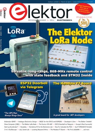
  • 1. The Meadow F7 Board A great board for .NET developers ESP32 Doorbell via Telegram “The UPS Man Always Rings Once” Andonstar AD407 Analogue Electronics Design BASIC for the ESP32 and ESP8266 Developer’s Zone The Elektor ‘Intelekt’ Chess Computer (1981) The Elektor LoRa Node The Enviro+ RPi-HAT ESP32 Doorbell via Telegram Europe’s Most Successful Start-up Accelerator? Hexadoku Homebrew PC for the Electronics Lab How-To: Calculate the PSCC Joy-IT DMSO2D72 Portable 3-in-1 Oscilloscope Lab, Sweet Lab Locating Wayward Wires The Meadow F7 Board My First LoRaWAN … and more lektorSHAREDESIGN SELL ELECTRONICS magazine SELL ESP32 DoorbellESP32 Doorbell SHAREDESIGN The Elektor LoRa Node Versatile, long-range, 868-MHz remote control with state feedback and STM32 Inside 8-Page Supplement:Start-ups atproductronicaFast Forward 2019 Edition 2/2020 | March & April | www.elektormagazine.com Edition2/2020–March&April2020 190356-B Cover 02-2020 EN.indd 1190356-B Cover 02-2020 EN.indd 1 06/02/2020 14:1006/02/2020 14:10
  • 2. C M Y CM MY CY CMY K Untitled-4 1Untitled-4 1 06/02/2020 09:2106/02/2020 09:21
  • 3. www.elektormagazine.com March & April 2020 3 In last November’s issue I hinted at our laboratory working on projects using the LoRa radio protocol. This protocol allows data to be transmitted over wide distances in a highly energy-efficient way. In the present issue you will find two introductions to this exciting technology. The Elektor LoRa Node is a flexible and configurable module that enables you to render your own projects “LoRa compatible“. As an example application - also suitable of course for full replication - we developed a remote control capable of switching an electric appliance over distances of several hundred meters, with feedback on the sender. As befits LoRa, such a node can be operated autonomously in the field (using Li-Ion cells). If you are keen to send sensor data to the Internet for access and use any- where in the world you should take a look at the article My First LoRaWAN. Here we describe how to connect a board to the open “The Things Network“ with minimal effort. You can either use an existing gateway in your area, or install your own inexpensive gateway which receives the sensor data over LoRa. Of course there are many more intriguing developments in the world of microcontrollers. One of them is Artificial Intelligence, and you can count on my colleagues and me to discover some innovations at the Embedded World exhibition, which we will report on later this year. Already available in our online store is the MAix BiT Kit that permits entry-level explorations into the fields of speech and image recognition, all programmable through the comfy Arduino IDE! More about it in the next issues and of course up-to-date at www.elektormagazine.com! Jens Nickel International Editor-in-Chief, Elektor Magazine Data Transmission with Ease The Circuit International Editor-in-Chief: Jens Nickel Editor-in-Chief, English edition: Jan Buiting Membership Manager: Denise Bodrone International Editorial Staff: Eric Bogers, Rolf Gerstendorf, Denis Meyer, Dr Thomas Scherer, Clemens Valens Laboratory Staff: Mathias Claussen, Ton Giesberts, Luc Lemmens, Clemens Valens, Jan Visser Graphic Design & Prepress: Giel Dols Publisher: Don Akkermans Elektor Magazine, English edition Edition 2/2020 Volume 46, No. 500 March & April 2020 ISSN 1757-0875 (UK / US / ROW distribution) www.elektor.com www.elektormagazine.com Elektor Magazine, English edition is published 6 times a year by Elektor International Media 78 York Street London W1H 1DP United Kingdom Phone: (+44) (0)20 7692 8344 Head Office: Elektor International Media b.v. PO Box 11 NL-6114-ZG Susteren The Netherlands Phone: (+31) 46 4389444 Memberships: Please use London address E-mail: service@elektor.com www.elektor.com/memberships Advertising & Sponsoring: Margriet Debeij Phone: +49 170 5505 396 E-mail: margriet.debeij@elektor.com www.elektor.com/advertising Advertising rates and terms available on request. Copyright Notice The circuits described in this magazine are for domes- tic and educational use only. All drawings, photographs, printed circuit board layouts, programmed integrated circuits, disks, CD-ROMs, DVDs, software carriers, and article texts published in our books and magazines (other than third-party advertisements) are copyright Elektor International Media b.v. and may not be repro- duced or transmitted in any form or by any means, including photocopying, scanning and recording, in whole or in part without prior written permission from the Publisher. Such written permission must also be obtained before any part of this publication is stored in a retrieval system of any nature. Patent protection may exist in respect of circuits, devices, components etc. described in this magazine. The Publisher does not accept responsibility for failing to identify such patent(s) or other protection. The Publisher disclaims any responsibility for the safe and proper function of reader-assembled projects based upon or from schematics, descriptions or information published in or in relation with Elektor magazine. © Elektor International Media b.v. 2020 Printed in the Netherlands 190364-B EN colophon_editorial.indd 3190364-B EN colophon_editorial.indd 3 06/02/2020 08:3006/02/2020 08:30
  • 4. 4 March & April 2020 www.elektormagazine.com This Edition No. 500 Volume 47 – Edition 2/2020 March & April 2020 Features Interview with Wienke Giezeman, Initiator of The Things Network 45 electronica Fast Forward 2020 Sign up for the Start-up Platform Powered by Elektor 46 “A Strong Supporter of Open Internet” Interview with Wienke Giezeman, initiator of The Things Network 49 The Meadow F7 Board A great board for .NET developers 67 Raspberry Pi Bash Command Cheat Sheet 68 Europe’s Most Successful Start-up Accelerator? HighTechXL, Eindhoven, The Netherlands This Edition Volume 47 – Edition 2/2020 March & April 2020 This Edition Volume 47 – Edition 2/2020 March & April 2020 6 ESP32 Doorbell via Telegram “The UPS Man Always Rings Once” 29 Regulars 16 Interactive Corrections & Updates || Questions & Answers 18 Analogue Electronics Design Case Study #1 — Section 2: Preamplifier optimized for MEMS microphone 34 Small Circuits Revival Capita Selecta from the Elektor Project Suggestions Box 74 Steeped in Electronics Ordering components from Ukraine and Russia 78 Lab, Sweet Lab A glimpse of The Holy Place — no unauthorized entry 84 How-To: Calculate the Prospective Short- Circuit Current or PSCC and choose the proper circuit breaker 87 Peculiar Parts, the series TMS1000 Series Microcontrollers 88 Starting Out in Electronics (2) Easier than imagined! 90 Developer’s Zone Tips & Tricks, Best Practices and Other Useful Information 104 Retronics: The Elektor ‘Intelekt’ Chess Computer (1981) Tiny Chess 86 ported to the Intel 8088 110 Beyond Electronics PCB Art — Pushing the Limits of Industrial Manufacturing 120 Elektor Store what’s available @ www.elektor.com 122 Hexadoku The original Elektorized Sudoku 190365-B EN Contents_Preview.indd 4190365-B EN Contents_Preview.indd 4 06/02/2020 08:3406/02/2020 08:34
  • 5. www.elektormagazine.com March & April 2020 5 Projects Next Edition Elektor Magazine 3/2020 Weather Station 2020 • Experiments with AI • Nixie Bargraph Thermometer 2.0 • Visualizing Sigfox Data • E-Scooter Dismantled • Balancing Robot with Arduino • Basic for ESP32: Applications • Triac Meets ATmega • FreeRTOS and ESP32: Timers • Single-Chip ARM A7 and M4 • Retronics • Small Circuits Revival • and more. Elektor Magazine edition 3/2020 covering May & June 2020 is published around 7 May 2020. Delivery of printed copies to Elektor Gold Members is subject to transport. Contents and articles subject to change. 6 The Elektor LoRa Node Versatile, long-range, 868-MHz remote control with state feedback and STM32 Inside 21 My IoT Button: A Button for the Web Part 1: IoT architecture 26 BASIC for the ESP32 and ESP8266 Programming with Annex WiFi RDS 29 ESP32 Doorbell via Telegram “The UPS Man Always Rings Once” 36 My First LoRaWAN With Blue Pill, LoRa Breakout Board and The Things Network 54 Practical ESP32 Multitasking (2) Task priorities 60 Sigfox and the IoT (3) First steps on the network 80 Optical Probe for Oscilloscopes Measure brightness fluctuations of lighting systems 82 The ’TABULA’ Project — An Update Tangibles with user feedback 93 Locating Wayward Wires Track and trace concealed and defective cables with ease and certainty 100 Homebrew PC for the Electronics Lab Tips on component choice and construction 46n, lektorSHAREDESIGN SELL ELECTRONICS The Elektor LoRa NodeLoRa Node Versatile, long-range, 868-MHz remote control with state feedback and STM32 Inside The Meadow F7 Board A great board for .NET developersA great board for .NET developers 49 71 Review: The Enviro+ RPi-HAT Measure air quality with a Raspberry Pi and the Enviro+ HAT 76 Review: Andonstar AD407 Better than its predecessor? 98 Review: Joy-IT DMSO2D72 Portable 3-in- 1 Oscilloscope productronica 2019 Start-up Guide (8-Page Supplement) 112 Distrelec - Powering the Future Education is the foundation for innovation, and innovation needs advocates. 114 They’re All Winners! Start-ups @ productronica 2019 117 Fast Forward Award Finals The FFA 2019 Jury report 118 FFA 2019 Sponsors Weller / Kurtz Ersa / Berstein / Almit 190365-B EN Contents_Preview.indd 5190365-B EN Contents_Preview.indd 5 06/02/2020 08:3406/02/2020 08:34
  • 6. 6 March & April 2020 www.elektormagazine.com The Elektor LoRa Node Versatile, long-range, 868-MHz remote control withVersatile, long-range, 868-MHz remote control with state feedback and STM32 Insidestate feedback and STM32 Inside PROJECTLABS 180666 EN The Elektor LoRa Node.indd 6180666 EN The Elektor LoRa Node.indd 6 06/02/2020 08:3706/02/2020 08:37
  • 7. www.elektormagazine.com March & April 2020 7 the LoRaWAN Node Experimental Platform, stuffed for ‘local’ LoRa only. • LoRa Button. Board no. 180666-2. Two required for this project. • LoRa AC Power Switch. Board no. 180666-1. Together the three elements form not only a remote control with a range of 10 to 20 times that of a consumer-level WiFi link on 2.4 GHz, but also a LoRa development platform with potential for LoRaWAN. We kick off with the main consumption, and size. Read here how we did it. The story that follows is kind of chronological, since with this project we like to share not just the final product and a quality write-up, but also the real-life problems we ran into, and the tools used to develop the project. We do so at the request of many readers. What’s being described In this article we cover the three elements mentioned above: • LoRa Node. Board no. 180516-1, The Elektor LoRa Node was born from the idea to have a compact PCB with support for rechargeable as well as non-recharge- able batteries, a common microcontroller like the LQFP48-cased STM32, and a type RFM95 LoRa module, also, the PCB was to fit in an enclosure that’s easily sourced from one of the bigger distributors, also, for the STM32 compiler, we… STOP! As the enclosure will co-determine the space available or the energy source, we need to discuss this first. The initial idea was to power the device from non-re- chargeable batteries. This was rejected since Elektor wants its contribution to battery waste to be as small as possible. So, a rechargeable battery solution was sought, as well as ease of replacement by the user. This would result in a small, serviceable, water-resistant node capable of operating not only in Elektor Labs’ comfy conditions, but also “out there in the wild” and conveying real-life environ- mental data. Further design aspects heavily debated during the project devel- opment period were the battery lifetime and the sensors to accommodate on or off the board. Clearly, we aimed to have a flexible and useful platform to explore LoRa and potentially LoRaWAN, not for ‘academic’ use in the airco’d and carpeted lab but ready to use in any (rough) place out there for the purpose of remote device on/off switching. From here, the challenge is the ‘squaring of the circle’ in terms of flexibility, power By Mathias Clauβen and Luc Lemmens (Elektor Labs) Convinced of the combined power of open-source hardware and software, Elektor smashes the myth that LoRa is for pros only. This article not only tells the story of persistence in electronics design in the face of real challenges, but also of a 3-element LoRa Node you can easily replicate for reliable on/off control with status feedback and covering distances 10 to 20 times those of consumer-level WiFi and 433-MHz ISM LPR. PROJECT DECODER LoRa intermediate levelÆ entry level expert level 4 hours approx. €150 approx. excl. cases USB UART, Arduino IDE, lab tool set Arduino STM32 Quick Features Lora Node • LoRaWAN Experimental Platform board with minimum parts stuffed • Li-Ion battery powered • User changeable cells • STM32F072C8T6TR ARM Cortex-M0 MCU • SPI F-RAM or Flash (optional) • Crypto co-processor (optional) • GPS module (optional) • USB interface (optional) LoRa AC Switch (slave device) • Relay state feedback to Node central • Switch contacts rated 5 A (1000 W at 230 VAC; (500 W at 115 VAC) LoRa Button (master device) • Low-energy design • Optional OLED display • Integral helical coil antenna • 100–500 m range to LoRA slave 180666 EN The Elektor LoRa Node.indd 7180666 EN The Elektor LoRa Node.indd 7 06/02/2020 08:3706/02/2020 08:37
  • 8. 8 March & April 2020 www.elektormagazine.com attempt to show the versatility of the board. PCB design and challenges After building the first prototypes some adjustments seemed in order. For the GPS module we needed some tweaks to get better reception. For sure, you can build a miniaturized antenna but you need to take the ground plane into account. The GPS module datasheet states a minimum PCB size for the antenna to work. Still, we were not satis- fied with the signal reception. After Version 1 of the board we ditched the Quectel L96 GPS module and replaced it with the GPS Module from the Elektor Store [2] as this was both cheaper and, easier to connect to the board as a quasi-external part. This caused further redesigns for the connectors used, so everything is now in a 0.1-inch raster allowing you to plug the module onto a breadboard. Then we have the RFM95W LoRa module that needs an antenna for sure. With the size and enclosure we selected, we wanted to use a DIY helical coil antenna for 868 MHz. If you desire even better reception, an external antenna is an option. We realized the design was a compromise between space, functionality and RF performance. Lessons learned. We already mentioned the use of Li-Ion batteries in 10440 (AAA) format, as found in e-cigarettes. These are easy to replace by the user and charged outside the device with a proper Li-Ion charger. To protect the cells from deep discharge a voltage monitor IC was included switch- ing off the LDO for the 3.3-V supply. Also added at this point was a 2-mm pinhole part to attach LiPo battery packs commonly used for drones. These small and flat cell packs come with a Molex 510005 or JST connector and offer a fine capacity/space ratio. This makes the whole design more flexible and allows the use of off-the-shelf rechargeable batteries that can be sourced from big warehouses starting with an A. Reverse-current protection was imple- mented using a ‘loadswitch’ device. Eventually we used the MAX40200 ‘ideal diode’ for this purpose, as it will discon- nect the supply voltage if it passes a certain amount of reverse current. A second one was added for the power supply towards the GPS module (K4), enabling the MCU to cut the power to the module in order to extend battery life. If To meet certain design aspects and requirements we stuck to thinking ‘modular’. With the full complement of components fitted you’d have a LoRaWAN device with a GPS module, crypto coprocessor, SPI F-RAM or Flash storage. All features are “nice to have” but you may not need them. It also implies that components not populated on the board will save money in the basic version, and no need to pay for features you’ll never need. As the pinout for the SPI F-RAM and SPI Flash modules is standardized, you can add your favourite module. The same for the crypto coprocessor, an ATECC608a: you can also choose to just add an I²C-EEPROM or an F-RAM chip, meaning you have a very flexible and use-con- figurable device available. The LQFP48-cased STM32F072 MCU now on the PCB is a Cortex-M0 based device with 64 kB of Flash and 16 kB of RAM, allowing you to even have USB for firmware updates or for use in your own applications. The nice thing about the STM32 series is the utter pin compatibility, meaning you can change the MCU without chang- ing the board layout. For example, the even lower power STM32L072, or an STM32L151 in case you need more computation power and Flash. The STM32F103 you commonly find on the ‘Bluepill’ board can be fitted on the PCB, too. The Quick Features box is just an element: the LoRa Node. The early beginnings The PCB was designed using KiCad, a free, open source, multi-platform, electronics design tool that’s gaining users every day, and not just hobby- ists. If you’d like to start out with KiCad we have a fine book available in the Elektor Store [1]. After a false start with “another” proces- sor, and some more stumbling in the dark, a board for the STM32F072 in LQFP48 case was designed, benefiting from that MCU’s Arduino IDE compat- ibility. This makes development pretty easy as you can now use most of your well-known Arduino libraries. As we didn’t have any incarnation of a quartz crystal on the board we resorted to the internal oscillator options. Here, this defaulted to 8 MHz for the MCU in order to reduce the power consumption, but ready for cranking up to 48 MHz if desired. The modular approach The Elektor LoRa Node board pictured in Figure 1 (early version) is not only the basis for the present project but will be used in spin-off projects to be published later this year in Elektor magazine. That’s why we will first take a tour of the components and other options that may be assembled on the board. The hard-core electronics fans among you may want to do a parallel tour by way of the circuit diagram printed in Figure 2. Figure 1. The LoRa Node control board with ’real estate’ allocated to functional blocks. Actually, you are looking at a minimally-stuffed LoRaWAN Node Experimental Platform. 180666 EN The Elektor LoRa Node.indd 8180666 EN The Elektor LoRa Node.indd 8 06/02/2020 08:3806/02/2020 08:38
  • 9. www.elektormagazine.com March & April 2020 9 runtime, and we also need to reconsider the under-voltage lockout. With our home-made antenna transmit- ting fine, the biggest challenges at this would be feasible but needs additional circuitry, in this case a DC/DC boost stage. As the boost stage will consume power all the time this may reduce you forfeit the GPS module you can have the MCU control that 3.3-V rail to power or disable other external circuitry. Powering the device from NiMH cells 20 40 41 42 43 45 46 10 14 15 16 17 29 32 33 6 5 4 2 3 CS 18 19 21 NSS SCK MISO MOSI RESET DIO0 DIO1 DIO2 16 15 14MOD1 RFM95W ANT 1810 GND GND GND 9 13 C1 4µ7 C2 100n 12 11 DIO5 DIO4 DIO3 6524 37C7 100n C12 100n 1 IC3 AT255F081-SSHD-X GND CS __ SCK SO/IO1 SI/IO0 WP/IO2 ___ HOLD/IO3 _____ 8 VCC 3V3 3V3 3V3 3V3 3V3 3V3 3V3 3V3 3V3 22 6 5 I2C_SCL I2C_SDA R8 4k7 R9 4k7 8 VCC SCL SDA 4 GND 1 2 3 7NC NC NC NC IC5 ATECC608A 12 13 GPSRXD GPSTXD 2 GNDEN 3 1 VIN 5 OUT 4 NC 2GPS_ACTIVE_IN K4 1 2 3 4 5 VCC GND GPSRX GPSTX 11 VSupply R6R7 150k150k 39 K6 K2 JTDO JTDI 7 RST 3 2 1 R2R10 LED2LED1 680 680 K5 K3 VUSB USBDM USBDP 1 2 3 4 VBAT GND + 25 26 27 28 PB12 PB13 PB14 PB15 30 31 PA9 PA10 CAN_RX CAN_TX 38 PB3 PA15 34 37 SWDIO SWCLK PA13 PA14 17 16 15 14 13 12 11 10 9 8 7 6 5 4 3 2 1 T1 SI2347DS BT1BT2 R1 100k C3 100n 3 VDD 1 2 IC1 TLV809K33 JP2 1 2 3OFF ON F1 0ZCK0050AF2E F2 0ZCK0050AF2E C15 4µ7 1 2 3 5 4 IC7 MAX40200 VIN GND EN OUT NC D1 PMEG3010EJ C16 100µ C19 100µ C20 100µ C21 100µ C4 470µ C18 100n C5 4µ7 1 3 2 5 GND GND IN EN OUT IC2 TLV75533PDBV C6 470n RESET ______ 19243648 VBAT VDDA VDD VDD VDDIO2 R5 10k 44 BOOT0 R4 10k R3 4k7 X1 ASH7KW 1 4 2 3 OE GNDOUTPUT VDD 3 4 PC14 PC15 NRST JP1 1 2 5 6 PF0 PF1 PC13 PB0 PB1 PB2 PB4 PB5 PB6 PB7 PB8 PB9 PB10 PB11 PA0 PA2 PA3 PA4 PA5 PA6 PA7 PA8 PA11 PA12 2335478 VSSVSSVSSVSSA I2C_SCL I2C_SDA USBDM USBDP IC6 MAX40200 R11 10k C14 4µ7 C13 100n C8C9C10C11C17 100n100n100n100n4µ7 S1 S2 Reset Boot IC4 STM32F072C8Tx ANT1 868MHz K11 ANT1 32 1 UVL PA1RST ____ 3V3 SPI_NOR_NCS 7 VBAT GND 3V3 PB12 PB13 PB14 PB15 PA9 PA10 SCL/PB6 SDA/PB7 PB8 PB9 GND 3V3 SWDIO SWCLK GND Figure 2. Circuit diagram of the LoRa Node control board. This is basically the LoRaWAN Node Experimental Platform board with a specific outfit of ICs. 180666 EN The Elektor LoRa Node.indd 9180666 EN The Elektor LoRa Node.indd 9 06/02/2020 08:3806/02/2020 08:38
  • 10. 10 March & April 2020 www.elektormagazine.com the input is below 2.97 V, it disables the HS switch IC7 and the supply voltage is cut as well for a period of 20 ms. Without a large buffer capacitor, high currents at start-up upset the UVLO and its input voltage will drop below 2.97 V, result- ing in a permanent loop of enabling and disabling the LDO. Adding a ‘big’ electro- lytic like C4 (Figure 3) made the power path work as expected. Fit it only if you find the two 100-µF MLCC solid caps too expensive. Also according to the datasheet, we don’t have a FET or diode protecting the batteries from being charged from the VUSB side. This job is done within the MAX40200 — if a reverse current flows the chip will cut power. This is also true if the voltage coming from VUSB exceeds that provided by the system batteries. The two LEDs on the board flag the board status reported by the MCU on port lines PB3 and PA15 a.k.a. ‘JTDO’ and ‘JTDI’ on pinheader K6. Software: the groundwork Although system software increasingly defines hardware functionality, to some it’s just black magic that needs to be ‘flashed’ into a chip. A comparison of lab time spent on software versus hardware shows many more hours dedicated to the former. How come? As already mentioned, you can program the board with your favourite Arduino IDE. For this the stm32duino project [3] did especially well in supporting a wide range of STM32 MCUs and STM32 boards. Formally adding the Elektor LoRa Node Experimental Platform was the first ‘cleri- cal’ task that needed to be done. In the Arduino core for the STM32 we had to edit a few files and add the board defini- tion. After some errors and unexpected software behaviour we got the template running and were able to start coding the first few lines. One thing you normally don’t care much about is the way the MCU generates the clock. On the older AVR chips you had a crystal and that was it. On the more recent MCUs though you have more options to generate the MCU main clock, often from internal PLL / FLL sources or high-speed internal RC oscillators. We decided to use the internal clock sources. They’re not great for frequency stabil- ity, but good enough to get us going. By allowing us to change the clock speed during runtime, going ‘slow’ saves power and going ‘fast’ yields higher throughput. The default value of 8 MHz for the core Down at the component level a few problems arose, including one with a 470-µF capacitor previously ahead of the undervoltage lockout device, IC1. If point appeared to be within the project software. Undeterred though we ran point-to-point communication in the RAW mode offered by the LMIC library. K3 K8 K7 K6 K5 K4 3V3 OLED GND SCL SDA LED BLUE GND SW K2 1 2 3 4 5 R1 GND SW 1 2 3 2 1 1 2 VBAT GND R4R3 1 2 3 4 5 6 GND VBAT FTDI_TXD FTDI_RXD 1 2 3 17 16 15 14 13 12 11 10 9 8 7 6 5 4 3 2 1 LED2LED1 180666-022-94 KD 680 680 270 3V3 R2 10k LCD1 0.96 ’’ Figure 4. LoRa Button schematic. This is the ‘sending’ or ‘master’ part of the Elektor LoRa Node. The OLED display is optional and its use requires deep thought about energy use! Figure 5. A special method for mounting the LEDs is applied on the LoRa Button board. Figure 3. Board space reserved for electrolytic capacitor C4, one of the largest parts on the board. 180666 EN The Elektor LoRa Node.indd 10180666 EN The Elektor LoRa Node.indd 10 06/02/2020 08:3806/02/2020 08:38
  • 11. www.elektormagazine.com March & April 2020 11 (Figure 6), then slowly lever the plastic upward over the pins using a screw- driver blade (Figure 7). If everything goes well, the metal pins will be exposed (Figure 8). The OLED display can then be inserted flat into the intended position, followed by the pinheader sockets, the angled pinheaders, and the PCB screw termi- nal blocks. This almost completes the construction, less the real button of course (Figure 9). Interlude: a DIY 868-MHz antenna The LoRa Button now needs an antenna for transmitting and receiving at 868 MHz. A quarter-wave ‘Marconi’ nal blocks, pinsockets, and pinheaders. These parts are essential for the basic version of the Elektor LoRa Node. The OLED display from the Elektor Store [3] (component: LCD1) is optional. When assembling the board, there are a few things that need to be considered. The LEDs, for example, have their bodies bent over and inserted in PCB holes so their faces are at the board underside, see Figure 5. For the OLED display more delicacy is in order because you either have to unsol- der the entire pinheader block or bodge a bit by removing the plastic shroud- ing around the pins in the pinheader. To remove the excess plastic, first bite into the plastic part between the pins and peripherals keeps power consump- tion modest yet is fast enough to process the LoRa stack. For accuracy in the RTC domain a 32.768- kHz oscillator was added (X1). It is optional. At the cost of a µA of current we gain UARTs that can be clocked from the crystal as well as an RTC that can wake up the MCU after a given timeframe. The LoRa Button For a simple input device to convey its state over radio and learn about things we propose the second component in the project, the ‘LoRa Button’. The schematic in Figure 4 shows that the LoRa Button has just a few resis- tors, a pair of LEDs, PCB screw termi- Figure 6. Use sharp cutters to snap into the plastic material between the pins until they are no longer held together. Figure 8. You now have a ‘naked’ pin row. Figure 7. Using a flat screwdriver blade, carefully lever up the plastic remnants surrounding the pins, and remove them. Figure 9. The almost completed LoRa Button board. 180666 EN The Elektor LoRa Node.indd 11180666 EN The Elektor LoRa Node.indd 11 06/02/2020 08:3806/02/2020 08:38
  • 12. 12 March & April 2020 www.elektormagazine.com sive solution for the project. Although the documentation with the SMPSU does not mention the need for a fuse at the AC side, we added F1 just to be sure. NTC (negative temperature coefficient) resistor R1 limits the supply inrush current, which can soar in these inverters. C1, C2 and common-mode filter L1 at the output of the AC/DC converter may appear overkill, but we did not rely on Mean Well’s state- ment that the module contains enough internal EMI interference suppression. Power switching. For this application a device from Omron’s G5RL-K1 series of bistable relays was chosen. These have a Set and a Reset coil, and a short excitation of either is enough to toggle the contacts. Although the relay contacts are rated for a maximum current of 16 A, fuse F2 melts at about 5 A to protect the copper tracks on the circuit board from burning out. Feedback. Theoretically the microcon- troller on the LoRa Node board should be able to keep track of the last action sent to the Slave device, i.e. is it on or off? But to be really sure of the condi- tion, a physical feedback of the output is no luxury thing, also because the position of a bistable relay is not certain when the project is reset. Remember: the circuit around optocoupler IC1 only indicates that RE1 is closed and that the mains voltage is present on termi- nal block K2. Whether the load actually works (i.e. whether it consumes power) is not revealed by the state feedback and should therefore be checked for real and on the spot. Manual operation. The idea behind this project is to be able to switch a load from a (large) distance by pressing a button. But if you are around anyway at the receiver end it’s great to be able to operate it manually without needing the LoRa Button and the LoRa Node. Moreover, if the LoRa connection is lost for whatever reason, it’s comfy if you can still switch gears. Mounting and installation. The solder- ing of the board has few challenges. Apart from the common-mode filter and (possibly) connector K3, it’s all plain sailing with through-hole compo- nents only. K3’s connector pads are quite large and even L1 is unlikely to throw a spanner in the solder works. equal a rod antenna or wound into a coil and compressed with 1-mm spaced turns. Either way, the wire is soldered to the ANT connector (Figure 10). The LoRa AC Switch Slave As an example of a slaved “output device’’ controlled by the Elektor LoRa Node as well as ‘listening’ to the LoRa Button, a power switch was developed for mains operated equipment consum- ing up to 1 kilowatt (kW). An optocou- pler returns the (on/off) state of the AC Switch Slave to the Lora Node. The board also houses a 100-230 VAC to 5 VDC power converter allowing the Lora Node and the AC Switch Slave to be powered directly from an AC power outlet. The real intelligence of the LoRa Switch Slave resides in the LoRa Node hardware and software, which is connected as a plug-in board. None the less, the Switch Slave provides these functions: • a 5-VDC supply rail; • load switching dimensioned for 115/230 VAC, 1 kW max.; • switch state feedback; • a local control (on/off) pushbutton. The schematic of the LoRa Switch Slave is given in Figure 11. We’ll look at the main components and the construction. Power supply. A 5-V, 2-W, AC/DC converter from Mean Well proved to be a compact, safe and relatively inexpen- antenna made from 1-mm diameter enamelled copper wire (AWG #18) is a good and low-cost option. Assuming a ground plane is present the wire should have a length of 8.635 cm in a vacuum but 8.2 cm in practice! That’s because of the air velocity factor of 0.95 [4]. Depending on the space available, the antenna wire may be left straight to K1 K2 L N PE PE N SW F1 60 mA T R1 -T MOD1 IRM AC/DC 2W 1 2 3 4 C1 100n C2 100n L1 ACM4520-231-2P-T +5V +5V C3 1µ 16V F2 5A +5V D1 1N4148 D2 1N4148 Re1 G5RLK1AEDC5 T1 T2 BS170 BS170 R2 R3 R7 R8 1k 1k R4 100k R5 47k R6 47k C4 10µ 16V IC1 CNY65 D3 1N4007 on +3V3 +3V3 S1 1 3 5 7 9 11 13 15 K3 16 14 12 10 8 6 4 2 1 2 3 4 180666-1 KD S R on reset set 10 10 ACin ACin DCout + DCout - Figure 11. Schematic of the LoRa AC Switch. This is not a ‘dumb’ device but it feeds the actual relay on/off state back to the LoRa Node. Figure 10. The feedpoint of the home-wound, quarter-wave antenna for the 868-MHz band is soldered to the ANT pad on the LoRa Button board (early prototype shown). Note the coiled construction of the antenna. 180666 EN The Elektor LoRa Node.indd 12180666 EN The Elektor LoRa Node.indd 12 06/02/2020 08:3806/02/2020 08:38
  • 13. www.elektormagazine.com March & April 2020 13 COMPONENT LIST COMPONENT LIST 180666 EN The Elektor LoRa Node.indd 13180666 EN The Elektor LoRa Node.indd 13 06/02/2020 08:3806/02/2020 08:38
  • 14. 14 March & April 2020 www.elektormagazine.com Software installation The complete software package for the Elektor LoRa Node is available at the expected place [6]. The archive file also includes a detailed installation proce- dure which cannot be printed here due to lack of space. When it comes to firmware development for the LoRa Node board you can choose the hard-core “C” way using either the STMCubeIDE, or the easy-peasy way with the Arduino IDE. For the latter, you need to download the Arduino IDE and the STM32 Arduino Core. In the Arduino IDE, add this url to the Additional Boards Manager: housing. We had to take the second row of contacts for granted — we simply couldn’t find a single-row socket strip with a suitable height. However, the footprint on the PCB for connector K3 was adjusted in such a way that normal 0.1-inch through-hole socket strips can also be used. They are useful if you choose a different, taller housing. You can also omit K3 altogether and solder the LoRa Node’s right-an- gled connector the to both PCBs, but then you can’t easily separate the PCB anymore. Pushbutton S1 is mounted on the housing and connected to the PCB with two wires. K3 employs only seven of the sixteen pins on this PCB. It has two options as discussed below but both assume the LoRa Node board has a standard 0.1-inch pitched, angled connector in position K5. The seven pins in positions 11 through 17 (see board 180516-1) are enough, but K3 can also be a 17-pin pinheader (cut to length) over the full length of K5. The Würth Elektronik connector identi- fied as K3 in the parts list may be more difficult to obtain compared to a custom cut pinheader. Still, we went for it because of its low height allow- ing the two boards, mounted at right angles, to be fitted in the recommended Web Links [1] KiCAD Like a Pro book: www.elektor.com/kicad-like-a-pro [2] GPS module from Elektor Store: www.elektor.com/open-smart-gps-serial-gps-module-for-arduino-apm2-5-flight-control [3] STM32duino project: https://github.com/stm32duino/Arduino_Core_STM32 [4] Velocity factor: https://en.wikipedia.org/wiki/Velocity_factor [5] STM32CubeProgrammer: www.st.com/en/development-tools/stm32cubeprog.html [6] Project software: www.elektormagazine.com/180666-01 [7] STM32 boards adding: https://github.com/stm32duino/wiki/wiki/Getting-Started COMPONENT LIST 180666 EN The Elektor LoRa Node.indd 14180666 EN The Elektor LoRa Node.indd 14 06/02/2020 08:3806/02/2020 08:38
  • 15. www.elektormagazine.com March & April 2020 15 STM32duino ‘gremium’ (Figure 13 — thanks guys). As a happy consequence, you no longer need to patch anything as described above, and you can simply select the Elektor LoRa Node board from the list of approved items. (180666-01) toggling the Reset button. Now you can upload new firmware to the board. For your benefit At the start of the article we said that the story was going to be partly chrono- logical. Since mid-December 2019, the Elektor LoRaWAN Node Experimental Platform board definitions have been merged into the official STM32Arduino Git repository, after complying with the rather strict conditions set by the https://github.com/stm32duino/ BoardManagerFiles/raw/master/ STM32/package_stm_index.json and install the STM32 Boards following the instructions posted at [7]. Now you have the STM32 core but for the Elektor LoRa Node you need to add a few things to your local filesystem. For Windows go to: %localappdata%Arduino15packages STM32hardwarestm321.7.0 and at the end of ‘Boards.txt’ add the contents of the file called Add_To_Board. txt we wrote for you. Also copy the folder: ELEKTOR_LORA_NODE_CORE_F072xC to the ’Versions’ folder. Now you should be good to go and ready to compile the software for the board. At the end you need to define the Boardsettings shown in Figure 12. At this point you are good to go to compile software for the board. To do an upload you need to install the STM32CubeProgrammer [5]. If you now wish to upload code, put the board into bootloader mode by pressing Boot and Figure 12. Espy and copy these board settings. Figure 13. This was just one of the the steps taken by Elektor Labs to get the LoRa Node (an incarnation of the LoRaWAN Node Experimental Platform) approved and registered as an STM32Arduino device. Elektor readers do not have to “enjoy” this administrative process; the project software is ready to roll. 4 SALE @ WWW.ELEKTOR.COM ªLoRaWAN Elektor Lora Node, 180516 V3.1 www.elektor.com/180516-1 ªLoRa Button board, 180666-2 v 1.2 www.elektor.com/180666-2 ªLoRa AC Switch board, 180666 1 V 1.1. www.elektor.com/180666-1 ªRFM95W-868S2 LoRa Transceiver, Elektor SKU 18715 www.elektor.com/18715 ªKiCAD Like a Pro book: www.elektor.com/kicad-like-a-pro ªGPS module (optional): www.elektor.com/open-smart-gps-serial-gps-module-for-arduino-apm2-5-flight-control 180666 EN The Elektor LoRa Node.indd 15180666 EN The Elektor LoRa Node.indd 15 06/02/2020 08:3806/02/2020 08:38
  • 16. 16 March & April 2020 www.elektormagazine.com Arduino Uno issues involving the bootloader Q: I recently bought the Elektor book C Programming with Arduino and started working with it enthusiastically. For this I also bought an Atmel ICE programmer from Microchip which works very well with Atmel Studio 7.0 (AS7), the IDE used in the book. Now I have noticed that the Arduino Uno can no longer be programmed by the Arduino IDE. Another Uno that I have still works well with the Arduino IDE software. Reconnecting the board, restarting the computer or the software and similar manipulations, doesn’t make any difference. I’ve searched several forums on the Internet, but I can’t find a solution to this problem. Do you have a suggestion or, even better, a solution? A: The thing that turns a microcontroller into an Arduino-compatible micro- controller is the Arduino bootloader. This is a small piece of software inside the MCU’s memory capable of writing a program it received somehow (mostly across a serial connection), to the MCU’s memory without overwriting itself. The Arduino IDE knows about the bootloader and employs the serial port (across USB) to program the Arduino board. Atmel Studio is totally unaware of Arduino or the Arduino bootloader, hence a special programming adapter is required to burn a program into the MCU’s memory. The programming adapter, like the Atmel ICE, connects to the MCU’s in-system programming (ISP) interface to gain direct access to the MCU’s memory. Without special measures it will overwrite all the memory contents including the bootloader. This explains why the Arduino Uno stopped working with the Arduino IDE: the bootloader is gone! AS7 with Atmel ICE can be used to repro- gram the Arduino bootloader. The file needed is [Arduino]hardwarearduino avrbootloadersoptibootoptiboot_ atmega328.hex where [Arduino] is the folder containing the file arduino.exe. Once in AS7, open ‘Device Programming’ (Shift-Ctrl-P). Then, on the ‘Memories’ tab in the ‘Flash’ section, click the ‘Browse for file’ button and navigate to the bootloader’s HEX file. Click ‘Program’ to flash the bootloader into the MCU. There are many ways of configuring AS7 to make it work with Arduino without deleting the bootloader every time you hit ‘Program’. Methods range from installing AS7 extensions to adapting linker settings. Search the Internet to find the method that suits you best. Interactive Corrections & Updates || Questions & Answers By Clemens Valens Updates of and additions to projects published in ElektorLabs Magazine spiced up with tips & tricks, tech advice, and answers to reader's questions. MCU’s memory. Without special measures it will overwrite all the memory contents including the bootloader. This explains why the Arduino Uno stopped working with the Arduino IDE: the bootloader is gone! AS7 with Atmel ICE can be used to repro- gram the Arduino bootloader. The file needed is avrbootloadersoptibootoptiboot_ atmega328.hex folder containing the file Once in AS7, open ‘Device Programming’ (Shift-Ctrl-P). Then, on the ‘Memories’ tab in the ‘Flash’ section, click the ‘Browse for file’ button and navigate to the bootloader’s HEX file. Click ‘Program’ to flash the bootloader into the MCU. There are many ways of configuring AS7 to make it work with Arduino without deleting the bootloader every time you hit ‘Program’. Methods range from installing AS7 extensions to adapting linker settings. Search the 190379-B EN Interactive.indd 16190379-B EN Interactive.indd 16 06/02/2020 08:4306/02/2020 08:43
  • 17. www.elektormagazine.com March & April 2020 17 changes, the serial port speed changes too. Unfortunately, the Arduino IDE does not allow the user to specify the speed of the serial port for uploading sketches. When you select an Arduino Uno board in the Arduino IDE, the IDE supposes that it runs at 16 MHz and requires an upload speed of 115,200 baud. If an Uno doesn’t run at 16 MHz, uploading a sketch will therefore fail. Similarly, an AVR Playground is expected by the IDE to run at 8 MHz with an upload speed of 57,600 baud. The simplicity of the Arduino IDE is appreciated by most of its users, but sometimes it can get in the way. The adventurous IDE user can try to modify the file boards.txt which contains all the information about the boards. However, there may be more than one of these files in your Arduino IDE installation. The keys to change are [Board].upload.speed and [Board]. build.f_cpu (where [Board] is the name of the board). The IDE has to be restarted to take any changes to this file into account. www.elektormagazine.com/labs/avr-playground-129009-2 Q: Is it possible to use the ATmega328 of an Arduino Uno board on the AVR Playground and vice versa? A: Even though the Arduino Uno and the AVR Playground are based on the same ATmega328 microcontroller, you cannot simply swap them. That’s due to the way the clock oscillator is used on the boards. The Arduino Uno runs off a 16-MHz clock driven by its 16-MHz crystal. By contrast, the AVR Playground defaults to using the MCU’s internal 8-MHz RC-oscillator. You can replace the MCU on an Arduino Uno by one used on an AVR Playground. The Uno will then work exactly as an AVR Playground running at 8 MHz. However, the other way around, i.e. replacing the MCU on an AVR Playground by one taken from an Arduino Uno, is only possible when the AVR Playground is equipped with a 16-MHz crystal (X1) and when its jumpers on K5 are on pins 1-3 and 2-4. With these conditions satisfied, the AVR Playground will function exactly as an Arduino Uno. But there is more to the story. The bootloader programmed in the MCU of an Arduino-compatible board is tuned to the MCU’s clock speed in order to configure the speed of the serial port used for uploading sketches. When the clock frequency New GPS for New Precise Nixie Clock It appears that the Maestro type A2035-H GPS module used in this project is no longer in production. However, Lantronix, who acquired Maestro in the summer of 2019, offers the A2235-H, a newer albeit smaller GPS module that does fit on our PCB. It needs two additional 2.2-kΩ pull-up resistors from the I2 C pins to the 1.8-V output of the module. You may also need some (Kapton) isolation between the PCB and the module to avoid a short circuit between the shielding of the module and a via underneath it. www.elektormagazine.com/labs/150189-6-digit-nixie-clock 190379-B-01 AVR Playground running from a 16-MHz crystal. AVR Playground running from its internal 8-MHz RC-oscillator. 190379-B EN Interactive.indd 17190379-B EN Interactive.indd 17 06/02/2020 08:4306/02/2020 08:43
  • 18. 18 March & April 2020 www.elektormagazine.com This sub-installment in the Analogue Electronics Design article series provides a documented and commented evaluation of the original microphone preamplifier used in the Bat Detec- torPLUS project [1], and discusses solutions to optimizing it for use with the MEMS microphone examined in Section 1 of this Case Study [2]. For a full appreciation of the electronics design task done it’s useful if not mandatory to refer to the circuit diagram of the microphone preamplifier mentioned a number of times, so for convenience it is shown as the highlighted section in Figure 1. We purposely reprint the entire schematic of the Bat Detector- PLUS to explicitly show the way the preamplifier is: • driven (from the microphone connected on K1); • loaded (by IC4A); • powered (symmetrically at ±4.5 V by IC1).   So you have ’the full picture’. But first, an evaluation of the original circuit. After all these years, the low-power opamp type TL062 with its 200 µA of quiescent supply current per amplifier is not so bad compared to many current low-power versions almost exclusively to be found in ever smaller SMD versions. Evidently there are now (much) better ones. The gain-band- width product (GBW) is 1 MHz and that is a stumbling block in the design, especially because substantial amplification is needed: here a whopping 1845 times. If we include the 400 Ω of the MEMS microphone in the total gain, then using only one opamp would yield a measly 540-Hz bandwidth. To increase the bandwidth, more successive amplifiers, each with less amplifi- cation and therefore more bandwidth are needed, here, three pieces. But how many should there be in practice, and does this outweigh the proportionally higher power consumption than a much faster opamp with higher power consumption? Nowadays there are “wicked-fast“ fast opamps like the OPA2889 dual opamp with its 75-MHz GBW at 20 times amplification and a current consumption of 0.92 mA for both amplifiers. But back to the number of opamps needed. That’s difficult to calculate because you should assume that the bandwidth per amplifier may not track that of a first-order low-pass filter. In addition, with more amplifiers in series, the bandwidth is also smaller than is the case with one amplifier. But for the sake of convenience, let’s consider this response to be like a first-order RC network. This certainly applies to equal sections used to dimension the lower limit; more sections then means a higher roll-off point for the lower limit. For a first-order high-pass RC filter, the transfer function is expressed as:   jωRC / (1 + jωRC) (eq. 1)   Due to the phase rotation, the actual voltage distribution is then:   ωRC / √(1 + (ωRC)2 ) (eq. 2)   For the roll-off point this equals ½√2. That’s the well-known ‘–3 dB point’ but for sticklers we note:   20log ½√2 = –3.0103   However, we want to know what the actual bandwidth will be when more sections are connected in series. Instead of ½√2 we take the factor x. Rearranging, we get:   ωRC = x / √(1 – x2 ) (eq. 3)   For example, for a –3 dB point, enter the value ½√2 for x and it turns out that this results in 1 exactly and with it the well-known standard formula that applies to the frequency of the –3 dB roll-off point:   f = 1 / (2πRC) (eq. 4) Analogue Electronics Design Case Study #1 — Section 2: Preamplifier optimized for MEMS microphone By Ton Giesberts (Elektor Labs) In this article series, experts in the field explore aspects of analogue electronics design that should benefit an increasingly ‘digital-only’ audience, and underpin that analogue is not black magic. In Case Study #1, Section 1 we discussed the MEMS microphone used for the first time in an Elektor project called Bat Detector-PLUS. In this installment we continue with design aspects of the sophisticated microphone amplifier in the project. all–analogue 191230 EN All-Analogue.indd 18191230 EN All-Analogue.indd 18 06/02/2020 08:4406/02/2020 08:44
  • 19. www.elektormagazine.com March & April 2020 19 First simulate... and only then design a PCB, or build a prototype on bread- board or on a piece of veroboard. If only to find out if more sections are needed or if something else needs to be adjusted. Often, simulating a circuit is faster than doing the maths on it. Simulation on the preamp showed that the final frequency range was 23 kHz to 58 kHz — too low! In our prototype, the upper frequency limit was even slightly lower at about 44 kHz. This is probably due to tolerance on the opamps as well as the lower supply voltage than stated in the datasheet for the GBW. The 1-MHz GBW rating for a TL062 is a typical value; maximum and minimum are not specified. And as already mentioned, the response of each section is probably not purely first-order. How many sections then... ... in case we want to use that good old TL062? It is recom- mended not to have the desired bandwidth determined by the limit of the opamp, its GBW rating being subject to consid- erable spread. The equally negative effects on distortion and intermodulation are not much of a problem here. It is better that this limit be substantially higher than necessary before the filtering, say a factor of 2, preferably 3, and let a capac- However, we want to learn the new roll-off if it’s known from one section. For example, if we take three sections as in the circuit, we should find the frequency where the attenuation is 1 dB. For convenience, we don’t take –3.0103/3 but just –1. From 20log x = –1 it follows that:   x = 10(-1/20)   (eq. 5)   The attenuation to be found for the –1 dB point then works out at 0.891251. Entering it into equation 3, ωRC equals 1.96523. Consequently, for three equal sections, the new low roll-off will be almost twice as high. In the case of a low-pass filter, the roll-off is then almost a factor of two lower. For n sections, the following applies:   x = 10((-3/n)/20) (eq. 6)   In the case of the TL062, a gain of 13.3 times (i.e. 100 / 7.5) for the middle section, means a roll-off at 75 kHz. The additional 4.7-pF capacitor in the feedback path further lowers the roll-off frequency to about 60 kHz per section and changes the frequency response to a higher order. C1 220µ C2 100n C3 100n C4 100µ R1 47k C5 10µ R2 47k C6 100n 3 2 6 1 5 7 4 IC1 TL061CP R35 100R C7 100n C8 100n C9 10µ C10 10µ BT1 9V K1 R3 4k7 0W5 D3 3V C11 100n +4V5 +4V5 -4V5 3 2 1 IC2A 5 6 7 IC2B 4 8 R6 100k C13 4p7 R4 7k5 R5 10k C12 1n R9 100k C15 4p7 R7 7k5 R8 10k C14 1n 3 2 1 IC3A R12 82k C17 4p7 R10 7k5 R11 10k 5 6 7 IC3B 4 8 C16 1n 3 2 1 IC4A C18 470p R13 10k R16 10k R17 10kR14 10k D1 BAT43 D2 BAT43 5 6 7 IC4B C19 10n R18 10k R19 36k R15 30k 4 8 R20 10k C20 10n T1 BC 548B +5V_PIC 1 3 2 IC5 LP2950ACZ-5.0 P1 50k C24 10µ C23 100n C22 100n +4V5 -4V5 +5V_PIC R21 10k R22 100k C21 1n R23 1M P2 100k T2 BC 548B R24 47k R25 10k -4V5 R26 10k +5V_PIC 1 2 3 4 5 6 7 8 13 14 15 16 9 10 11 12 S1 -4V5 -4V5 +5V_PIC R27 10k R28 10k LED1 LED2 -4V5 SIGNAL MUTE T3 BC 558B R30 4k7R2947k T4 BC 548B +4V5 K2 R31 39k C25 10n Line out C28 10n C26 10n R33 10k R34 47k -4V5 T5 BC 548B R32 4k7 C27 47µ +4V5 RA0 17 RA1 18 RA2 1 RA3 2 RA4 3 RA5/MCLR/Vpp 4 RA6 15 RA7 16 RB0 6 RB1 7 RB2 8 RB3 9 RB4 10 RB5 11 RB6 12 RB7 13 VDD 14 VSS 5 IC6 PIC 16F1827 -I/P OUT- 5 OUT+ 8 VCC 6 GND 7 SVR 2 IN+ 3 IN- 4 MODE 1 IC7 TDA8541T /N1 LS1 IC2 IC3 IC4 TP3 Mod. TP2 TP1 0V -4V5 MIC. + P3 10k IC2, IC3, IC4 = TL062CP -4V5 150346 - 11 Figure 1: Full circuit of the Bat DetectorPLUS with the 3-stage microphone preamplifier highlighted. 191230 EN All-Analogue.indd 19191230 EN All-Analogue.indd 19 06/02/2020 08:4406/02/2020 08:44
  • 20. 20 March & April 2020 www.elektormagazine.com cation of 2.561), eight sections in series provide a bandwidth of 107.3 kHz, as shown in Figure 2. It’s not the best solution. Also, the 1-nF coupling capacitor has to be tweaked; if we really assume 10 kHz this would result in an ‘awkward’ 7 nF. Using a readily available 10-nF capacitor, the low roll-off frequency will be 6.6 kHz. Another concept could be: fast opamp(s) and active filters as an amplifier, with a Butterworth or Chebyshev characteristic, for example. Signal to noise ratio For the signal-to-noise ratio this will not be a good design either, the first stages ruling the roost. At the input a non-in- verting amplifier may have suited better. It results in hardly any attenuation due to the input resistance and the resistors in the feedback of the first stage can be chosen considerably lower, which benefits the signal-to-noise ratio and dynamic range. The MEMS microphone used has a maximum output resistance of 400 Ω. With an electret microphone, the value is even higher. The frequency response is not matched to the microphone. Unfortunately, most manufacturers do not specify the frequency response above 20 kHz or so. Often it is only specified up to 10 kHz, which is exactly the information we need for our appli- cation! It would be nice if we could measure and verify that personally. Absolute accuracy is not needed — a comparison with the known response of a wideband ultrasound source is adequate. The ramifications though for home construction are another problem. Outlook The closing Section 3 of this Case Study will be published in edition 2/2020 (March & April) of Elektor Magazine. It will discuss more all-analogue challenges and solutions including preamplifier dynamic range, input noise, opamp bias currents, and 2- and 3-pin microphone modelling. Stay tuned. 191230-01 itor in the feedback circuit determine the desired bandwidth. Let’s see where we end up. The higher limit of the opamp’s effective frequency range — and consequently the lower maximum gain that can be set per section — naturally has an impact on the number of sections required. With the conser- vative use of a 3 times higher bandwidth, the amplification per section should not exceed:   1 MHz / 360 kHz = 2.78 times.   Intuitively, it means a lot of sections will be needed! Let’s call the amplification per section A (rounded off at 1850) and the number of sections, n. Then:   An = 1850 (eq. 7)   To calculate n back we write:   n = (log1850) / (log A) (eq. 8)   Substituting 2.78 for A, then n equals 7.36. In that case at least eight sections are needed, or two quad opamps, i.e. TL064 ICs with a total current consumption of 1.6 mA. This is not very practical and using a faster (dual) opamp seems a much better choice, especially in regard of the number of parts and their space consumption on the circuit board. The advantage of more opamps is a larger physical distance between the relatively large output signal and the amplifier input, resulting in less risk of oscillation due to parasitic coupling. With the lighting fast SMD opamp it is recommended to use SMDs for the other parts too. Parasitic coupling to the microphone has no effect as it is a shielded device. In really bad cases only, the effect can occur on the connections such as connectors and cables to and from the circuit boards. Wanted: bandwidth! As a check, the theoretical bandwidth can be calculated again. With eight sections, less gain is needed per section. In the case of n sections, the amplification per section is:   A = n √1850 (eq. 9)   With eight sections, the amplification needed per section is just 2.561 times. Equation 6 yields 0.95775 for x. Using equation 3 you can calculate that the new roll-off shifts by a factor of 3.33. So the expected new roll-off frequency, without capacitors in the feedback circuit, becomes:   1000 / (2.561 × 3.33) = 117.3 kHz.   This is just shy of the desired bandwidth while we have already gone from three to eight sections. Yet it is not enough for the previously mentioned reasons, because it is still short of the desired bandwidth. In a simulation with 7.5 kΩ at the input and 19.2075 kΩ for feedback (for a theoretical amplifi- Web Links [1] Bat Dectector-PLUS article: www.elektormagazine.com/magazine/elektor-201607/29128 [2] Analogue Electronics Design (1): www.elektormagazine.com/191143-01 Figure 2: The graph shows the effect of eight identical amplifiers in series (source = 0 Ω). 191230 EN All-Analogue.indd 20191230 EN All-Analogue.indd 20 06/02/2020 08:4406/02/2020 08:44
  • 21. www.elektormagazine.com March & April 2020 21 Ideas for new applications in the inter- net of things (IoT) are arising all the time. Many ideas are experimental or are unlikely to quickly find a home in the actual IoT. The vision of a self-re- plenishing refrigerator will probably fail to materialise because most of us prefer to do our food shopping according to our current taste and in a trusted shop. The IoT button is an interesting idea somewhere between a serious applica- tion and a playful pastime. An IoT button could be used, for example, to: • start or stop something; • order something; • call someone; • count something. ment, and the same is true for using cloud services. In the second article of this series, we will use a bit of hardware, some software and several configurations to perform our first experiments, which will enable us to try out our own ideas with this sort of IoT. IoT architecture The architecture of a modern IoT appli- cation, regardless of its specific purpose or the ultimately chosen service, can be represented as shown in Figure 1. The individual devices on the left side of the figure can be sensors, actuators, or a combination of the two. Sensors measure parameters – for example, environmental conditions such as temperature, monitor The potential applications are manifold and could be in the personal realm as well as the business realm. The basic idea is to use a hardware module in the form of a button to send a signal. Where the signal is sent, what actions are associated with it and which systems are involved, as well as whether it actually consists of a single button, are initially undefined. First we should take this idea as an opportunity to describe and under- stand modern IoT architecture. In the first article of this series, we focus on the interactions of the components and explore the functions and possibilities of cloud services. Very simple experiments can be performed in the IoT environ- My IoT Button: A Button for the Web Part 1: IoT architecture By Dr Veikko Krypczyk (Germany) There’s a never-ending stream of new applications in the IoT environment. One of them is the IoT button – a button that can be programmed and used for any desired purpose. It requires a network connection and draws its logic from the cloud. The first article of this series is about the IoT architecture based on serverless cloud computing, as well as the interaction of hardware and software. 190303 EN My IoT-Button – Part 1.indd 21190303 EN My IoT-Button – Part 1.indd 21 06/02/2020 08:4706/02/2020 08:47
  • 22. 22 March & April 2020 www.elektormagazine.com and MQTT, for communication with the devices. IoT cloud services The major cloud providers also offer functions that are adapted to the specific requirements of IoT. The market leaders for IoT solutions are the Windows Azure, Amazon Web Services, Q-loud and Oracle Cloud platforms. Choosing the right platform is not easy, and it is strongly dependent on the intended purpose in each case [1]. The following criteria should be considered when choosing a platform: • Platform features: Which specific features are available — such as device management, authentication, authorisation and data forwarding. • Platform attributes: This includes the aspects of data protection, encryption, and the user interface (dashboard). • Integration: Supported programming languages, SDKs and interfaces. • Other: This includes criteria such as community and documentation, support, costs and the price model. Most IoT cloud services can be tested free of charge up to a certain level of use. Documented examples in the form of source code and configuration param- eters are usually available on the provid- er’s website. IoT device integration The IoT devices are connected to the cloud service over the public Internet. • Device-based authentication: It enables multiple login and authenti- cation of devices, for example based on tokens or certificates. • Secure communication: It provides a secure communication channel through which data can be exchanged with the IoT devices. • Data forwarding: Some data can be evaluated and processed directly in the cloud, while other data must be forwarded to other services for further processing. In the figure these services are shown as backend services of an existing company IT system. That would be the case with an industrial IoT application. Simpler applications only forward the data to a program for evaluation and visualisation.   In the case of the IoT button, the responses triggered by pressing the button must be defined. For example, another IoT device in the form of an actuator could be driven. Along with these tasks, the IoT cloud should be as communicative as possible, which means it should be able to function with a large number of devices. It should be flexible enough to offer programming interfaces for a variety of systems. These interfaces should preferably be provided by easily integrated SDKs (libraries) in various target languages, such as C, Python and Java. Generic communica- tion via a REST interface (see the inset “What is REST?”) should also be possible. The IoT cloud should additionally support various protocols, such as HTTPS, AMQP the status of systems – or send a signal when the state of a monitored system changes. Actuators, by contrast, carry out responses – such as opening or closing a radiator valve. Some IoT appli- cation use both sensors and actuators. In a certain sense, these applications act as closed-loop systems operating under the control of a remote application system. Other IoT scenarios only involve the acquisition or monitoring of a state or status. In the case of our simple IoT button, the only thing that is monitored is pushing the button. The information, which is that the state of the button has changed, is transmit- ted over a network, which is usually the Internet. The signal is received by a service on a server. The specific services tailored to the requirements IoT appli- cations are grouped in what is called an IoT cloud. This IoT cloud plays a key role in all of this – it acts as a server, making it the communication partner of the IoT devices. This is called server- less computing because only selected functions are used in this case, rather than a complete server. Of course, the services run on the server of a service provider, but you don’t have to worry about configuration, administration, or any other secondary activities. At a higher load level, for example with a large number of calls to the service, additional resources are provided automatically (horizontal scaling). This is also something that you normally don’t have to worry about as a user. The core functions of the IoT cloud are: Backend Services Company IT IoT Cloud as Pre-Integration Stage Device Device 190303-005 EB Figure 1: Basic architecture of an IoT application with a cloud backend. 190303 EN My IoT-Button – Part 1.indd 22190303 EN My IoT-Button – Part 1.indd 22 06/02/2020 08:4706/02/2020 08:47
  • 23. www.elektormagazine.com March & April 2020 23 MQTT and HTTP protocols, enabling a large degree of compatibility with many devices. The integrated device manager is a core function of Cloud IoT. The managed devices can be modified using a dashboard, and control by software code is also possible. The device manager determines the identity of a device and provides unambiguous authentication. End-to-end encryption is used for secure data transmission. In technical terms, Cloud IoT Core is a serverless service that can be scaled horizontally with quantitative growth of demand without noticeable delays. It is based on a REST interface, making it largely independent of the device systems. The fees for the service depend on the usage and are graduated. Cloud IoT Core from Google is free up to a maximum monthly data volume of 250 MB. This service is there- fore suitable for experiments, proto- typing, personal projects, or relatively small commercial projects. Similar cloud services for IoT — but almost exclusively for industrial customers — are offered by Oracle [5], Amazon (AWS) [6] and the Q-loud platform [7]. The services from ThingsBoard [8] also deserve mention. They offer an open-source cloud platform for IoT purposes. It can be used entirely free of charge if you install the associated software on your own computer. In manner of speaking, you create your own IoT backend, which is known as ‘on-premise’. You are personally respon- sible for installation, maintenance and operation. An attractive feature is the variety of supported systems – among other things, everything can run on various Linux distributions (Ubuntu, devices and the Azure cloud portal. It is a cloud-hosted backend that supports the connection of a large number of devices. The devices are integrated through SDKs, which are available for various platforms and programming languages. The IoT hub also offers functions for manag- ing the connected devices. Each device has its own identity with access data or certificates, and each device can be independently activated or deactivated directly in the browser via the dashboard. This functionality is also offered through APIs, to allow developers to manage IoT devices in their own applications The online documentation provides compre- hensive step-by-step instructions. For example, reference [3] describes how to integrate a Raspberry Pi with the IoT hub and receive data from the device. The Azure IoT Hub can be used free of charge for prototyping and for commer- cial or personal use, as long as you can live with a restricted number of calls. The Free Edition does not incur any charges if you do not exchange more than 8,000 messages per day with the device and the size of an individual message does not exceed 0.5 KB. The Cloud IoT Core service from Google [4] has similar characteristics. This is a fully managed service that can be used to manage devices and exchange data over the Internet. Cloud IoT Core can also interact with other cloud services from Google, such as Google Big Data Analytics, or ML services such as Dataflow, BigQuery, BigTable, ML, Data Studio or BI tools from partners. This enables effective evaluation, process- ing and visualisation of IoT data in real time. The service supports the usual How this connection is established is not important in the first instance. Along with direct wired connection of station- ary devices (LAN), wireless connec- tion over a local network (WLAN) or a mobile communication network (LTE) is possible. This depends on the appli- cation, the available infrastructure, the selected hardware, and the power consumption. For our IoT button, we assume the simplest possible integra- tion into an existing local WLAN. The IoT button should be versatile and the housing should be compact (for example, similar to a light switch for a floor lamp), so there are clearly defined require- ments for the hardware. This means our choice is limited to hardware platforms (boards) with easy WLAN connectivity and the lowest possible power consump- tion, especially in standby mode. These aspects will be addressed in more detail in the second article of this series, in the descriptions of the experiments and initial prototypes. If we ignore the restrictions with regard to size, power supply and wireless connection to the network, there is a significantly larger selection of poten- tial platforms for our IoT device. For example, if the IoT button is intended to be persistently located in one place, then it can be powered from the AC mains, so the power consumption in standby mode is less critical, and a wired LAN connec- tion is also an option. IoT cloud providers Next we have to choose a provider for the IoT cloud services. The Azure IoT Hub service from Microsoft [2] is intended for bidirectional communication between IoT Extruded enclosuresExtruded enclosures standard and heatsinkstandard and heatsink More than 5000 different enclosure styles: hammfg.com/electronics/small-case 01256 81281201256 812812 sales@hammond-electronics.co.uksales@hammond-electronics.co.uk Advertisement 190303 EN My IoT-Button – Part 1.indd 23190303 EN My IoT-Button – Part 1.indd 23 06/02/2020 08:4706/02/2020 08:47
  • 24. 24 March & April 2020 www.elektormagazine.com Web Links [1] Platforms comparison: www.informatik-aktuell.de/betrieb/virtualisierung/iot-in-der-cloud-erkenntnisse-und-erfahrungen-eines-plattformvergleichs.html [2] Microsoft Azure IoT Hub: https://azure.microsoft.com/en-us/services/iot-hub/ [3] RPi in Azure: https://docs.microsoft.com/en-us/azure/iot-hub/iot-hub-raspberry-pi-kit-c-get-started [4] Google IoT Core: https://cloud.google.com/iot-core/ [5] Oracle IoT cloud: www.oracle.com/internet-of-things/ [6] Amazon IoT cloud: https://aws.amazon.com/de/iot/ [7] Q-loud cloud: www.q-loud.de/ [8] ThingsBoard: https://thingsboard.io/ [9] REST: www.codecademy.com/articles/what-is-rest [10] RESTful API: https://restfulapi.net/ The functions of this server or cloud service include the typical tasks of an IoT backend, which means managing devices, collecting and visualising data, The software from ThingsBoard is also offered as a managed cloud solution with graduated fees based on the volume of use, starting at USD 10 per month. CentOS, Red Hat), Windows, or a Raspberry Pi 3. The latter option could be particularly attractive for maker and community projects or prototyping. What is REST? When a client and server communicate with each other over the Internet, the relevant API is usually based on REST [9][10]. REST is the abbreviation of REpresentational State Transfer. RESTful APIs are based on standardised protocols such as HTTP(S), URI, JSON or XML. The following criteria are decisive:   • Client-server model: Communication takes place on the basis of a client-server model. The objective is flexible and generic use of the services across platform boundaries. • Stateless: Communication is always stateless. Every request from the client to the server must be complete. The server cannot access any data from previous requests. • Caching: Clients can store (cache) responses from the server. The allows network outages to be bridged over and enables temporary offline operation. The cached data can be used as an alternative for renewed requests, instead of using a new response from the server. • Uniformity: The services use a uniform interface that is decoupled from the provided service.   A RESTful API is usually implemented with HTTP or HTTPS. To use the services, the client sends a request to the server and receives a response from the server. This is done by URL using HTTP methods such as GET, POST and PUT. A request consists of four components: endpoint, method, header, and data. An endpoint is composed of a root endpoint, a path, and optional parameters. For example, https:// api.github.com is the root endpoint of GitHub and /users/veikkoef/ repos is the path to the author’s repository. Together they form the endpoint https://api.github.com/ users/veikkoef/repos. Parameters can also be added – for example, ?query1=value1&query2=value2. For the methods you can choose from GET, POST, PUT/PATCH and DELETE. GET stands for read operations, which means reading data. GET requests only access the server for reading, so they can be sent as often as desired. GET is the default method. POST is used for create operations, which means creating a data set. POST can have side-effects. For example, a POST call can change fields in a database or launch processes on the server. PUT/ PATCH is used for update operations, and DELETE is used to delete data. The third component of a request is the header. The header serves to provide information for the client and the server. This can be used for many purposes, such as authentication or provision of information about the subsequent content. The fourth and final component of a request is the body, which is the data to be sent to the server. The body area is only relevant for the POST, PUT, PATCH and DELETE methods. Request URL HTTP Method Request Headers Request Body 190303-006 EB Structure of a RESTful request. 190303 EN My IoT-Button – Part 1.indd 24190303 EN My IoT-Button – Part 1.indd 24 06/02/2020 08:4706/02/2020 08:47
  • 25. www.elektormagazine.com March & April 2020 25 you a much better understanding of the relationships and makes it easier to design your own devices. 190303-03 processing events, and remote proce- dure calls for controlling devices. The functions are provided via a REST API, making them system and device agnos- tic. Graphic layers for processing incom- ing events can be defined conveniently using the Rule Engine (Figure 2). Conclusion and outlook We have presented an overview of the architecture of an IoT solution whose core component is a cloud service for managing IoT devices and for receiv- ing and forwarding data. In the second article of this series, we aim to put this knowledge into practice by designing a prototype of an IoT device in the form of an IoT button. Although such devices can be purchased ready-made, experi- mentation is worthwhile because it gives 4 SALE @ WWW.ELEKTOR.COM ªMy Journey into the Cloud (book):  www.elektor.com/my-journey-into-the-cloud Figure 2: Event processing can be defined graphically (source: ThingsBoard). 4 SALE @ WWW.ELEKTOR.COM www.elektor.com/my-journey-into-the-cloud www.driven-by-kurtzersa.com 191007_Ersa_Anzeige_Elektor_Productronica-2019_185x59mm.indd 1 09.10.2019 13:00:13 Advertisement 190303 EN My IoT-Button – Part 1.indd 25190303 EN My IoT-Button – Part 1.indd 25 06/02/2020 09:1906/02/2020 09:19
  • 26. 26 March & April 2020 www.elektormagazine.com Since an ESP32 is practically an ESP8266 with more power, after the introduction of the first version for ESP8266, a function- ally identical version was also designed for ESP32. At the time of writing this article, it is still in beta stage, but it should be final by March. If you like to develop small projects with network connection, you don’t have to struggle with the Arduino IDE and C/C++ anymore. BASIC is just simpler. In addition, the use of this BASIC variant for non-commercial, private use does not incur any costs. You might be tempted to give it a try? Annex BASIC Annex WiFi RDS [1] is based on the original concept of ESPbasic [2], on which the developer Francesco Ceccarella a.k.a. “chicciocb” collaborated at the time. However, Annex is not just another BASIC variant, but a completely revised suite BASIC for the ESP32 and ESP8266 Programming with Annex WiFi RDS By Peter Neufeld (Germany) Annex WiFi RDS (Rapid Development Suite) is a development environment originally designed to use the BASIC programming language on inexpensive ESP8266 modules. Meanwhile an ESP32 version is also available. Those who have so far programmed the 8-bit controllers from Atmel/Microchip with AVR-BASIC now have access to the 32-bit performance class. Features Annex WiFi RDS comprises these functions: • Integrated IDE via web server, use with web browser (optimized for Chrome and Firefox). • BASIC interpreter with floating point (double precision) and string variables, multidimensional arrays (float and string) and subroutines. • Syntax highlighting with context-sensitive help. • Programmable web and file server. • Supports OTA updates (firmware updates via WLAN). • Supports asynchronous events (interrupts, timers, web access, UDP etc.). • Breakpoints, immediate execution of commands, display of variables, single step. • Access to all I/O pins, 1-Wire, SPI, I2C, PWM, Servo, NeoPixel, USART. • Error handling, watchdog. • TCP (HTTP GET and POST). • UDP communication. • Sending e-mails via SMTP SSL server. • AJAX, ESP-NOW, MQTT and FTP communication (client). • IMU/AHRS fusion algorithms 6 and 9 DOF (Madgwick and Mahony). • PID controller (4 channels). • Windows-based utility suite (Annex Toolkit) with: • Flasher, File Manager, Backup/Restore, HTML Converter, Serial Port Monitor, OTA Update Server, UDP Console and IP Scan Tool. 190400 EN BASIC for ESP32.indd 26190400 EN BASIC for ESP32.indd 26 06/02/2020 08:4906/02/2020 08:49
  • 27. www.elektormagazine.com March & April 2020 27 support — on the other hand, these functions also consume memory and therefore limit the scope of your own programs. However, the necessary means are available to communicate with external devices on the protocol level from your own BASIC subroutines. For example, it is also feasible to address peripherals not listed here via SPI or I2 C with your own code. Annex WiFi RDS is only available in English. However, the developer is very active and responds quickly to feedback in the forum on the project website [1]. From the project website [3] the IDE for Windows systems can be downloaded as a ZIP archive and unzipped anywhere. The included application ANNEX-toolkit.exe allows the installation of the BASIC inter- preter on ESP modules. Hints for the installation are given in the Installation box. Once the firmware including interpreter and IDE as well as optional examples have been installed on the ESP controller and the controller is accessible via WLAN, everything can be done completely on the PC in the window of the browser which has loaded the IDE website in the controller. The software is specially optimized for Firefox and Chrome. In addition, it is also possible to communicate over the serial interface using the Annex Toolkit during development, which is helpful for that offers improved functions, higher reliability and optimized use of the capabilities of the Espressif controllers. In addition, appropriate documentation was also created. The functional range of the IDE including the BASIC inter- preter is amazing (see Features box). The complete software is in the microcontroller and runs in the web browser, which shows the integrated website. The ESP module provides either a WLAN access point and a web server under the IP address 192.168.4.1 or you connect the module to your WAN via (static) DHCP and note the IP address received from the router or configured there. Using the latter, the ESP can also synchronize the time and date with an Internet time server without an additional hardware clock. IDE Unlike compiler-based approaches for ESP controllers such as the Arduino IDE, the Annex firmware contains a fixed, non-con- figuration-dependent, integrated set of functions and drivers for common peripherals (see Hardware Support box). This is both a blessing and a curse: On the one hand, everything is already stored in the module to address all common hardware and immediately run any script code using this with full language Installation The installation and commissioning in your own WLAN is described in detail at [4]. Below is a brief summary of the most important points: • The firmware and any other files are transferred to an ESP module via the serial interface or USB and its memory may be deleted beforehand. • Log in in the access point mode (delivery status) of the ESP module or better integrate the module into your own WLAN as a WLAN client. • Set basic configurations such as LAN parameters, passwords, time zone/DST, Autostart BASIC program, OTA server, etc. Now everything is ready for browser-based loading, editing, debugging and execution of BASIC programs. Hardware Support The following devices, actuators and sensors are directly supported with dedicated commands and functions: • DHT11, DHT21 and DHT22 temperature/humidity sensors. • DS18B20 temperature sensor. • BME280 Temperature, humidity and air pressure sensor. • APDS9960 Distance, light (intensity and colour) and gesture sensor. • BNO055 absolute orientation sensor. • HC-SR04 ultrasonic sensor (distance measurement). • DS1307 and DS3231 RTC clock module. • PCA9685 PWM/SERVO module. • LCD with HD44780 via I2 C; 1/2/4 lines of 16/20 characters each. • LCD with ST7920 with 128 × 64 pixels monochrome. • Graphic OLED display with SSD1306 or SH1106; 128 × 64 pixels monochrome. • Graphical LCD with ILI9341; 320 × 240 pixels in 16 bit color. • 7-segment display with TM1637; 4 digits. • 7-segment display with TM1638; 8 digits plus 8 LEDs and 8 buttons. • 7-segment display with MAX7219; 8 digits. • Dot-matrix display with MAX7219; 8 × 8 dots. • Color LEDs Neopixel WS2812. • Dot-matrix display with neopixel WS2812; 8 × 8 dots. • Infrared interface; bidirectional (common RC protocols). Figure 1: The Annex Serial Flasher tool for transferring the firmware to an ESP module. 190400 EN BASIC for ESP32.indd 27190400 EN BASIC for ESP32.indd 27 06/02/2020 08:4906/02/2020 08:49
  • 28. 28 March & April 2020 www.elektormagazine.com troubleshooting. In parallel to the output of data via the serial interface, there is also an output to an area of the IDE called Wlog, which allows development e.g. with a notebook without a cable connection to the ESP module. It is even possible to work with several modules in parallel. Further aspects To ensure that the BASIC interpreter requires as little RAM as possible, the BASIC script is copied from SPIFF memory to a designated area in flash memory for execution, so that only the list of program lines, the branch identifiers and the list of user-defined subroutines need to be loaded into the scarce module memory. This is slightly slower than direct execution in RAM, but it saves RAM in favour of variables, thus allowing relatively large programs. This is less of a problem with ESP32, which has four times more RAM than the ESP8266. Another performance consideration is that an ESP controlle rmust always be able to execute multiple activities in the background (web server, file server, etc.). It therefore needs sufficient free RAM for these tasks. Parallel-performed actions inevitably affect the execution speed of its own code. The developer says that Annex-BASIC is largely compatible with the well-known PC variants GW-BASIC and Visual Basic and shares many concepts, ideas and syntax with these models. There is also compatibility with the Micromite project [5], a BASIC variant for PIC32 microcontrollers. The interpreter is based on the MiniBasic project [6] and the text editor on the EditArea project [7]. Naturally the execution speed of the interpreter cannot keep up with that of BASIC compilers. But for the usual tasks the interpreted BASIC is well suited on ESP controllers, suffi- ciently fast, reliable and very easy to use thanks to its brows- er-based nature. Again according to the developer, the BASIC on an ESP8266 in the “1980s BASIC benchmark” is about two to four times slower than under Micromite at 48 MHz clock. Relative to what this IDE has to offer, this is not a bad performance. In the article “Hourglass with ESP8266 and Annex WiFi RDS” in the next Elektor edition there is an instructive practical example based on this attractive IDE. The version for ESP32 has been equipped with some useful extensions for this SoC. 190400-03 Figure 2: The Annex Editor in the browser window with the example “Hello World”. Figure 3: Output of the example “Hello World”. Web Links [1] Annex WiFi RDS: https://sites.google.com/site/annexwifi/home [2] ESPbasic: www.esp8266basic.com [3] Downloads: https://sites.google.com/site/annexwifi/downloads [4] First Steps: https://sites.google.com/site/annexwifi/home/first-steps [5] Micromite: http://geoffg.net/micromite.html [6] MiniBasic: https://malcolmmclean.github.io/minibasic/web/MiniBasicHome.html [7] EditArea: www.cdolivet.com/editarea/ 4 SALE @ WWW.ELEKTOR.COM ªESP32 solo www.elektor.com/esp32-solo-1-wifi-bt-ble ªESP32 DevKitC www.elektor.com/esp32-devkitc 190400 EN BASIC for ESP32.indd 28190400 EN BASIC for ESP32.indd 28 06/02/2020 08:4906/02/2020 08:49
  • 29. www.elektormagazine.com March & April 2020 29 Delivery folks and some postmen don’t usually have the patience or the time to call again, and later in the day you’ll find a Telegram for you! As soon as the doorbell rings, the circuit we’re about to describe sends a message note in your mailbox either advising of the parcel pickup location, or of a scheduled alternative for the second delivery attempt. ESP32 Doorbell via Telegram “The UPS Man Always Rings Once” It happens to all of us — you’re at home and there’s a caller at the door but for some reason or other you do not hear the doorbell buzz or ring! No problem if the person at the door has your phone number handy as he or she will be able to get hold of you. In all other cases, Catch-22 governs, which is especially annoying when you stayed home desperately waiting for a parcel delivery within a certain time frame. Here now comes a DIY project to end such inconvenience. PROJECTLABS By Luc Lemmens (Elektor Labs) 191145 EN ESP32 Doorbell via Telegram.indd 29191145 EN ESP32 Doorbell via Telegram.indd 29 06/02/2020 08:5106/02/2020 08:51
  • 30. 30 March & April 2020 www.elektormagazine.com project we had to grapple with a most unusual phenomenon that ultimately took a lot more time to overcome than expected and planned, see the ‘Close Encounters’ text frame. Hardware: M5Stack ESP32 Basic Core With minor modifications to the software, this project can be used with any ESP32 or -8266 module. For this project though we went for the delightful M5Stack ESP32 Basic Core module available from the Elektor Store, see the @ www.elektor. com promotion and Figure 1. It’s a compact module in a neat housing with all ot his thrown in: • a graphics display; • a set of pushbuttons; • a loudspeaker; • a built-in rechargeable battery. The I/O lines on the M5Stack ESP32 Basic Core are accessible on connectors at the outside. However, if you open the back of the box and remove a plug-in board, you’ll find a 30-way extension connector for your homebrew hardware. For small extensions like this one, the extra hardware fits on a board equal in size to the M5Stack module itself. With an extra part for the housing, for which designs for 3D printing can be found abound on the web [2], you have a neatly finished device with not much extra effort to boost the project from an experimen- tal prototype to a box that also looks good in the living room. In short: this M5Stack module is great as a foundation for many ESP32 designs, ranging from project development platforms to ‘closed’ or ‘turnkey’ devices (start-ups,-r-u-lis- monochrome cartoons [1]. Back to the doorbell, how could we forget? Provided your Telegram app is active and connected to the Telegram server (by Wi-Fi or mobile network), it will alert you of a visitor at your doorstep no matter where you are. If you are dead sure who it is and completely trust that person, you can even return a ‘message’ that operates an electric door opener, meaning you don’t even have to scurry to the front door, or, as they used to do in certain cities on Holland, holler down the stairwell and pull the door rope. Telegram meets ESP32 — with a hiccup In this article we will see that Telegram is easy to set up and link to a ‘bot’ our automated intelligent processing. In our case we mean remote communication and control using an ESP32, specifically, to send a message when a key is pressed and to translate a (possible) answer into the activation of a relay. Naturally the options are not limited to this relatively simple application — the concept can easily be adapted and expanded to meet personal requirements. The ESP32 (and its predecessor called ESP8266), continues to get exten- sive coverage in many Elektor projects and books. Here, we’ll be using the ESP32 as a smart module that interacts with the outside world through Wi-Fi. Together with the well-known Arduino development environment and the UniversalTelegram bot library, develop- ing ‘simple’ applications like our doorbell should be a piece of cake. In reality though, during the development of this to your smartphone or computer on which an app called Telegram is running. Telegram, its makers say, "is a cloud- based mobile and desktop messag- ing app with a focus on security and speed.” For sticklers, the official name is Telegram Messenger. Like many 100% Internet driven communication tools for the masses, Telegram comes in various guises. Like mobile apps for: • Phone/iPad; • Android; • Windows phone; as well as desktop apps for: • PC/Mac/Linux; • MacOS; • Web-browser. Telegram is an instant messaging service not unlike WhatsApp in terms of function- ality. Both services are linked to your mobile phone number. On top of that, Telegram also offers to register your username, enabling your account to migrate with you when you get a new mobile number. There are more subtle and less subtle differences between the two messaging services and as expected, the Internet abounds with comparisons, bashing, glorification, fans, haters, and debate. If you are curious now, stop reading here for a moment and experience the sparse if not Spartan, Telegram website with its PROJECT DECODER ESP32 intermediate levelÆ entry level expert level 3 hours approx. €85 approx. Arduino IDE, regular lab tools Arduino M5Stack IoT Figure 1: The M5Stack ESP32 Basic Core module available from the Elektor Store. 191145 EN ESP32 Doorbell via Telegram.indd 30191145 EN ESP32 Doorbell via Telegram.indd 30 06/02/2020 08:5106/02/2020 08:51
  • 31. www.elektormagazine.com March & April 2020 31 starts by downloading the Telegram app from the App Store or Google Play. Installing that app is plain sailing — the account gets linked to the mobile phone number. Once that’s done, it’s best to install the corresponding Telegram app on your PC or Mac as well, which works out differently once the connec- tion between Telegram and the ESP32 sketch is made. inserted from the copper side (‘bottom’ of the PCB) upwards and get soldered on the component side. The short pins are inserted into the M5Stack module socket and the plastic part of K2 also serves as a spacer between the two circuit boards. Telegram installation The next step is to create an account on Telegram on your mobile phone, which tening?). In principle, you can also use the M5Stack and our extension board to build a complete doorbell installation. The built-in loudspeaker can compete with a ‘real’ doorbell in terms of volume, and a separate doorbell button can be wired in parallel with, or in lieu of, the optocou- pler’s output transistor. The ringing signal should be added in the Arduino sketch, and the logic level at GPIO17 inverted if the button is connected like this. However, this will not be discussed here, we will limit ourselves to a doorbell extension that’s connected to an existing installation! Schematic Figure 2 shows the schematic for the ‘Telegram’ed’ doorbell — it couldn’t be simpler. We assume that the M5Stack module is externally powered on USB, meaning the additional hardware only provides the control of a door opener via T1 and RE1, as well as connection to the doorbell button via optocoupler IC1. Our doorbell extension can there- fore be connected directly to an exist- ing doorbell system, so the two wires of the doorbell button are connected to K1 of our circuit. Traditionally, an electric doorbell is normally supplied with an AC voltage, but the bell voltage has never been a standard. Depending on the installation, this can be anything between 6 V and 24 V and there will probably also be exotic variants outside this range. This alternating voltage is present on the button wires as long as the button is not pressed and on K1 as well. The optocoupler translates the presence of this voltage into a logic level at the ESP32’s GPIO17 line — the level at rest (i.e. when not ringing) is low, and high when the button is pressed. Then there is the BT1 connec- tion which is intended to optionally (re) connect the 3.7-V lithium battery fitted as standard in the M5Stack module. Note the polarity: the red wire at the positive, and black wire at the negative terminal of BT1. The extension board contains only through-hole components and should be easy to assemble. However, do pay special attention to K2 because it’s mounted in an unusual way for such a standard part (Figure 3). Normally the short sides of the pins get inserted into the PCB from the component side and then soldered. In this case though we do it the other way around: the long pins are K1 button K2 opener R1 2k2 R2 10k IC1 FOD814 +3V3 +5V D1 1N4148 RE1 G5V-H1 5DC T1 BC337 R3 10k GPIO17 GPIO5 +3V3 +5V BT1 1 3 5 7 9 11 13 15 17 19 21 23 25 27 29 2 4 6 8 10 12 14 16 18 20 22 24 26 28 30 191145-1 KD K3 Figure 2: Schematic for the doorbell using the powerful combination of Arduino, ESP32 and the free online messaging app and service called ‘Telegram’. Figure 3: Recommended method of mounting K2: the long pins are inserted from the copper side (‘bottom’ of the PCB), pushed in upwards, and soldered at the component side. 191145 EN ESP32 Doorbell via Telegram.indd 31191145 EN ESP32 Doorbell via Telegram.indd 31 06/02/2020 08:5106/02/2020 08:51
  • 32. 32 March & April 2020 www.elektormagazine.com API. Keep this token in a safe place, as it can be used by anyone to control the doorbell bot. Consequently, we blurred the token in the setup dialogue of our own bot pictured in Figure 4. In this dialogue with BotFather, click on the framed link (‘t.me/...’) to open a chat window for the new bot which will also be added to the contact list. This bot is now ready for use, although it still needs to be linked to the Arduino sketch for the doorbell extender. Arduino sketch In the software download of this project you can find the sketch DOORBELL.INO, i.e. the source code for the ESP32 firmware [3]. This sketch can be touched up and in its current form is mainly intended to showcase how Arduino/ESP32 and Telegram work together to simplify control systems. Especially the operation of an electric door opener is a “vulnera- bility” as people could hack into the bot and open the door with no more than their smartphone or computer. Elektor accepts no liability whatsoever for any damage that may result from the appli- cation of this project! In the sketch, our M5Stack module requires registering on the local wireless Wi-Fi network, and access to the Telegram-bot you just created. The credentials of your Wi-Fi network are entered in lines 17 and 18, while the token reported back by BotFather has to be entered in line 21. Hence the above advice to create the bot on your computer, permitting the token to be easily copied into the sketch. After all, it’s not exactly a set of characters you can easily recall and retype. Once the Arduino IDE installation is successfully completed, the sketch will compile without any problems. In the Tools menu — when the M5Stack gets connected to a USB port of the computer — the correct board (M5Stack-Core- ESP32) and the virtual COM port have to be set in order to upload the sketch to the ESP32. That done, the sketch will launch, connect to the network, and the name of the Wi-Fi network and the IP address of the doorbell extender will appear on the M5Stack’s LCD. The bot has to be activated after each restart of the sketch by sending the /start command via the chat window in Telegram. The bot must then provide feedback including an overview of the commands it supports. opener. This bot has to be created first in Telegram and this is done by search- ing for ’BotFather’ in the contacts list. BotFather itself is a bot that helps to create your doorbell bot using a chat dialogue. After entering the command /newbot the dialogue commences, asking for a name (displayed later in the Telegram contact list) and for a bot username. The latter should always end with the characters ‘bot’. Note the slash ( / ) at the start of each bot command. When this process is successful, the BotFather will notify you and display a code (‘token’) needed to authorize the new bot to send requests to the Bot Using the mobile phone number, sign in to the Telegram app on your computer. The app on the phone will display a verification code that needs to be typed back into the computer, after which Telegram will be active there. The sketch on the ESP32 will work with a ‘bot’, which is easy to imagine as a kind of automatic answering machine. It can respond to commands received via a Telegram chat message or send messages via Telegram that are triggered by events in or near the ESP, such as reporting a key press or sending an ADC value. In this project, the commands may control a door Figure 4: Screendump showing how we fared in the lab with the use of BotFather. Token details struck out on purpose. Close Encounters of The ESP32 Kind Just imagine: your carefully crafted source code compiles without error messages, gets uploaded to the ESP32 just fine, and the circuit initially seems to work as expected. Seems. Further research though reveals the microcontroller is always resetting when a message arrives via Telegram! All checked & tried — no obvious mistake found. So, you recompile and test the program on another computer and to your amazement the ESP32 does just what’s expected of it! You check again if both computers run the same versions of the Arduino IDE and the libraries — no discrepancies to be found. At your wit’s end, on the first computer, you completely remove ‘Arduino’. That’s no ordinary uninstall, which apparently leaves debris in hidden folders anyway. You do a fresh install of ‘Arduino’ and all problems are gone. The exact nature of the problem at Labs? We still have no idea and we won’t be bothered to find out. Since then we learned that the Arduino IDE _may_ behave erratically. Even if it was the first occasion ever we ran into such an issue, as far as Elektor Labs are concerned, it was the last occasion too! 191145 EN ESP32 Doorbell via Telegram.indd 32191145 EN ESP32 Doorbell via Telegram.indd 32 06/02/2020 08:5106/02/2020 08:51
  • 33. www.elektormagazine.com March & April 2020 33 [4], and with the examples that come with it, it doesn’t take much effort to get started. Our doorbell sketch is based on the ‘custom keyboard’ example, showing h o w t o s e n d control buttons to the Telegram app, w h i c h i s a v e r y handy option, so you don’t have to bother typing control commands yourself in the chat window. The must-have subrou- tine is handleNewMes- sages doing the processing of incom- ing messages. In four If statements the commands and messages are handled which our bot understands: • Start; • status; • Ignore; • Open. To be able to send messages, the sketch needs the chat ID which gets saved in the variable ThisChat after receiving the first ‘/start’ command. The pushbutton (i.e. doorbell) is captured in an interrupt; note the IRAM_ATTR attribute that’s required for the declaration of an ESP interrupt service routine, all for correct handling of course. (191145-01) Daily use When the doorbell rings, a message gets sent via the Telegram app to your computer or smartphone. You can respond by opening the door yourself or by using the /Open button to operate an electric door opener (if there is one). The /Ignore button waives this option, and the /status button (busy checking the connection to the doorbell extender) appears again at the bottom of the chat screen. These commands can also be typed and sent via the chat window, be aware though they are case sensitive! The UniversalTelegram bot library actually does most of the work in this project. This library and its documentation can be found at COMPONENT LIST Web Links [1] Telegram Messenger: https://telegram.org/ [2] 3D printer files for M5Stack case: https://github.com/m4k3r-net/M5Stack-3DPrintFiles [3] Arduino sketch: www.elektormagazine.com/191145-01 [4] UniversalTelegram bot library: https://Github.com/witnessmenow/Universal-Arduino-Telegram-Bot @ WWW.ELEKTOR.COM ªM5Stack ESP32 Basic Core www.elektor.com/m5stack-esp32-basic-core-development-kit ªPCB no. 191145-1 V1.0 www.elektor.com/191145-1 191145 EN ESP32 Doorbell via Telegram.indd 33191145 EN ESP32 Doorbell via Telegram.indd 33 06/02/2020 08:5106/02/2020 08:51