SlideShare uma empresa Scribd logo
1 de 24
1 
 
CHAPTER II 
Introduction 
Sodium carboxymethyl cellulose (Na‐CMC or only CMC) is water soluble cellulose ether which permits 
the preparation of water solutions with a viscosity which may vary between a few mPa‐sec and several 
thousand mPa‐sec. 
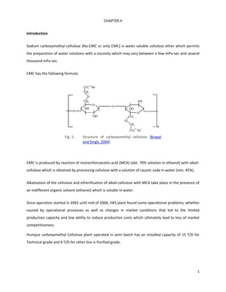
CMC has the following formula: 
 
Fig. 1:  Structure  of  carboxymethyl  cellulose  (Biswal 
and Singh, 2004) 
 
CMC is produced by reaction of monochloroacetic‐acid (MCA) (abt. 70% solution in ethanol) with alkali‐
cellulose which is obtained by processing cellulose with a solution of caustic soda in water (min. 45%). 
Alkalization of the cellulose and etherification of alkali‐cellulose with MCA take place in the presence of 
an indifferent organic solvent (ethanol) which is soluble in water. 
Since operation started in 2001 until mid of 2006, HKS plant found some operational problems, whether 
caused  by  operational  processes  as  well  as  changes  in  market  conditions  that  led  to  the  limited 
production capacity and low ability to reduce production costs which ultimately lead to loss of market 
competitiveness. 
Humpus carboxymethyl Cellulose plant operated in semi batch has an installed capacity of 15 T/D for 
Technical grade and 4 T/D for other line is Purified grade. 
 
 
2 
 
2.1  PROCESS DESCRIPTION 
The entire CMC‐plant consists of the following process groups:  
Tank farm 
Here,  all  the  liquid  raw  materials  introduced  into  the  process  are  stored  and  prepared.  Likewise  the 
dosing is effected from here according to the respective formula. 
Cellulose preparation 
Here, the cellulose raw‐material, delivered in sheets, is ground, stored and dosed. 
Production line for technical CMC 
a) Reaction and stripping unit 
b) Drying unit 
c) Milling and screening unit  
d) Blending unit 
e) Weighing and packing unit 
Production line for  purified CMC 
a) Reaction  unit 
b) Washing  and  extraction  unit 
c) Alcohol  stripping and  recovery  unit  
d) Drying  unit 
e) Milling  and  screening  unit 
f) Blending  unit 
g) Weighing  and  packing unit 
 
Utilities 
 
Here, the supply of steam, cooling water (32 °C), chilled water (5 °C), compressed air and process water 
are prepared and kept ready for operation of the production of CMC. 
3 
 
Rectification  and purification  of  the entire diluted and polluted ethanol from the above‐mentioned 
process lines 
  2.1.1  Tank Farm  
The concentrated   ethyl‐alcohol, needed for   the reaction is delivered   by a tank‐truck and filled by 
pump P‐1.08 into storage tank B‐1.04.  If required, the alcohol temperature may be reduced by spray 
cooling. The used water of this spray cooling is collected in tank B‐7.01 and delivered by pump P‐7.01 
back to cooling tower W‐7.01. 
The required  amount  of  alcohol for  every  reactor‐batch  is  delivered   by pump P‐1.05  via heat‐
exchanger  W‐1.01 to the respective reactor R‐3.01  for technical CMC or R‐4.01 for purified CMC. 
Prerequisite  for  this  dosing  of  alcohol  to  one  of  the  reactors  is  the  correct adjustment of the 
temperature. As long as the temperature is too high, the piping route for the alcohol remains in reflux 
operation back to tank B‐1.04. As soon as the adjusted temperature value is reached, the piping route 
for dosage of alcohol into the reactors is automatically released. 
The  amount  of  alcohol  needed  for  the  reaction  is  controlled  fully  automatically  by  a  computerized 
system according to the recipe needed for the required type of CMC. 
The concentrated alcohol needed for the preparation of the MCA‐solution in tank R‐1.01 is affected by 
means of pump P‐1.04. 
Diluted Ethyl‐Alcohol 
The  diluted  and  purified  ethyl‐alcohol  with  a  concentration  of  approx.  75  %,  received  from  the 
rectification unit after heat‐exchanger W‐5.05, is collected in tank B‐1.05. 
For the first production of this diluted washing alcohol, concentrated alcohol from tank B‐1.04 via pump 
P‐1.05 and process‐water are delivered to tank B‐1.05. 
The batch‐wise required amount of diluted alcohol to the slurry‐tanks R‐4.02 and R‐4.03 is delivered to   
these slurry‐tanks by pump P‐1.06 after passing heat‐exchanger W‐1.02 for temperature adjustment. 
4 
 
By manual operation of three‐way valve HVK 1160 it is possible to run the alcohol in a closed cooling 
loop via heat‐exchanger W‐1.02  back to tank B‐1.05, and thereafter if the adjusted alcohol temperature 
is reached, start the delivery to the slurry‐tanks R‐4.02 and R‐4.03. 
The continuous feed of diluted alcohol to belt‐filter F‐4.02 is done by means of pump P‐1.07. 
Soda‐Lye 
The soda lye, delivered by a tank‐truck, is stored in a tank B‐1.02. The amount of soda‐lye required for 
every reactor‐batch is delivered by pump P‐1.03 to the respective reactor R‐3.01 for technical CMC or R‐
4.01 for purified CMC, being controlled fully automatically by a computerized system according to the 
recipe needed for the required type of CMC. 
The tank for soda‐lye B‐1.02 and all soda‐lye pipes can be get heated by steam in order to prevent soda‐
lye from solidification (approx. 10‐12 °C). 
MCA‐Solution 
The MCA is delivered in solid state in plastic bags. These bags are opened manually and the MCA is 
conveyed into the dissolving tank R‐1.01 equipped with an agitator R‐1.01.1. Alcohol from tank B‐1.04 is 
conveyed into this dissolving tank R‐1.01 by means of pump P‐1.04. 
To prevent environmental pollution and to protect the personnel, the MCA‐dust containing air is sucked 
off by ventilator V‐1.01, and the MCA dust separated in cyclone separator F‐1.01 is recycled into tank R‐
1.01. 
For completion of the dissolution of MCA in alcohol, the double jacket of tank R‐1.01 is heated by hot 
water. The internal hot water circuit is established by pump P‐6.01. Steam is fed to this internal circuit 
by injector P‐6.08. 
The  prepared  MCA  solution  is  delivered  to  the  storage  tank  B‐1.01  by  means  of  pump  P‐1.01,  and 
further on the amount of MCA‐solution required for each batch is transported to the reactors R‐3.01 
and R‐4.01 via pump P‐1.02 being controlled fully automatically by a computerized system according to 
the recipe needed for the required type of CMC. 
2.1.2 Cellulose Preparation and Dosing  
5 
 
This operational group is designed for purified linters and for wood‐pulp produced in form of sheets. 
For CMC  production  it  is  necessary  to grind  the  cellulose  mainly  to  make it powdery. Only in that 
form, the cellulose can be used to produce CMC of very high quality. 
The  wood  pulp  sheets  are  fed  manually  to  belt‐conveyor  H‐2.01  with  integrated  metal  detector  H‐
2.01.1.   As metal parts are hazardous and may cause dust‐explosions in the cellulose mills, the motor of 
the belt   is stopped automatically if any metal is detected. 
From the belt‐conveyor H‐2.01 the cellulose sheets are fed to the pre‐cutter Z‐2.01 where the sheets 
are cut in order to get a free flowing product which can be transported pneumatically and which can 
easily be dosed to the fine‐grinding mills Z‐2.02 and Z‐2.03. 
The precut cellulose is transported pneumatically by ventilator V‐2.01 via pressure‐release vessel A‐
2.01 (safety installation) to filter‐cyclone F‐2.01 where all the cellulose (including the dust) is separated 
and falling via cell‐feeder X‐2.01 into the intermediate storage bunker B‐2.01 which is used as head 
container for the subsequent fine grinding mills Z‐2.02 and Z‐2.03. 
The filter‐tubes of the filter‐cyclone F‐2.01 are cleaned automatically by pulsed air jet. 
The filtered transport air passes ventex‐valve A‐2.04 (safety installation) and is discharged by ventilator 
V‐2.01 through the roof of the building. 
The intermediate bunker B‐2.01 is equipped with a distribution device B‐2.01.1 for precut cellulose so  
that the filling  level  of  the  integrated  discharge  screw‐conveyors  H‐2.02  and  H‐2.03  is  always  kept  in 
optimum position. 
By these screw‐conveyors H‐2.02 and H‐2.03 the cellulose is dosed via magnet cascades A.2.02 and A‐
2.03  to  the  subsequent  fine‐grinding  mills  Z‐2.02  and  Z‐2.03.  Here  the  cellulose  is  powderized  to  an 
optimal particle size for the reactivity in the reactors R‐3.01 and R‐4.01. 
In  order  to  minimize  the  hazard  risk  of  thermal  depolymerization  of  the  cellulose  by  the  released 
grinding energy, the mills Z‐2.02 and Z‐2.03 are cooled by cold water. 
The fine‐ground cellulose is transported pneumatically by ventilator V‐2.02 via pressure‐release vessel 
A‐2.05  (safety  installation)  to  cyclone  F‐2.02  where  most  of  the  cellulose  is  separated  from  the 
transport‐air and falls via cell‐feeder X‐2.02 into the dosing bunker B‐2.02. 
6 
 
As the total load  of cellulose‐dust and transport‐air is too  big for the cyclone F‐2.02, the transport‐air 
containing most of the cellulose dust is passing the total filter separator  F‐2.03  where  all the  cellulose 
dust is separated  and  returned automatically via cell‐feeder X‐2.03 into the dosing bunker B‐2.02. 
Afterwards the filtered transport‐air is discharged via pressure‐release vessel A‐2.06 (safety installation) 
by ventilator V‐2.02 through the roof of the building. 
The filter‐tubes of the total filter separator F‐2.02 are cleaned automatically by pulsed air jet. 
This  dosing  bunker  B‐2.02  is  placed  on  load‐cells  and  equipped  with  a  weighing  computer  for  exact 
dosing  of  the  required  quantity  of  cellulose  to  the  reactors  R‐3.01  for  technical  CMC  and  R‐4.01  for 
purified CMC, according to the recipe needed for the required grade of CMC. 
In  order  to  have  always  an  optimum  filling  level  available  for  the  integrated  shaft  of  the  discharge 
double  screw‐conveyor  H‐2.02.2,  this  dosing  bunker  B‐2.02  is  equipped  with  a  distribution  device  B‐
2.02.1. 
By means of the bi‐directional screw‐conveyor H‐2.04 either reactor R‐3.01 for technical CMC or reactor 
R‐4.01 for purified CMC are charged with the required amount of cellulose. 
2.1.3. Reaction Unit for Technical CMC 
The reactor must facilitate the diffusion operation of the liquid reaction components into the cellulose 
after distribution of the reactants and control the thermodynamic and kinetic preconditions required for 
all chemical reactions. 
The complete batch is controlled fully automatically by a computerized system. A typical reactor batch is 
consisting of the following single process steps: 
a) Dosing of alcohol 
According to the recipe the required quantity is dosed by pump P‐1.05 via heat‐exchanger W‐1.01 to the 
reactor R‐3.01. 
For the adjustment of special alcohol concentrations in the reactor for special recipes it is also possible 
to feed water via the alcohol line into the reactor. 
7 
 
Prerequisite for any dosing of alcohol or water is to operate the jacket cooling of the reactor R‐3.01 with 
chilled water. 
b)   Dosing of cellulose 
Shortly after the start of alcohol dosing, the required amount of cellulose is charged from dosing bunker 
B‐2.02 via screw‐conveyor H‐2.04 into the reactor R‐3.01. 
c) Evacuation of reactor R‐3.01 
When  the dosing  of alcohol  and cellulose  is finished  the reactor  is closed, cooling of condensers W‐
3.01 and W‐3.02  is started, reflux of alcohol from condensers W‐3.01 and  W‐3.02 is  switched  on  via  
valve  3126  HVK  in direction to reactor R‐3.01 and vacuum‐pump  V‐3.01 is started. 
The reason for operation under vacuum is: 
Adiabatic  cooling  of  the  reactor  content  by  evaporation  and  condensing  of  alcohol  and  discharge  of 
atmospheric  oxygen  in  order  to  avoid  a  decrease  of  the  degree  of  polymerization  of  cellulose  by 
oxidation during alkalization. 
It is also   possible   to exchange   the   atmospheric   oxygen   by nitrogen, especially for the production 
of very high viscosities of purified CMC. 
d) Dosing of soda‐lye 
When the required  vacuum in reactor R‐3.01 is reached  and the temperature of  the  alcohol/cellulose 
mixture  is  below  15 °C,  the  required  quantity  of soda‐lye  from  tank B‐1.02  via pump P‐1.03 is 
dosed  to the reactor.  For an optimum  and  homogeneous activation  of the cellulose  the  temperature  
of the  alkalization   mixture  should  not  be  too  high. So  if the  temperature reaches  18 °C,  the  
dosing  of  soda‐lye  is  stopped  automatically   and  only started again when the temperature  is below 
15 °C. 
e) Alkalization 
When  all  the  required  soda‐lye  is  dosed  the  alkalization  time  is  running.  Depending  on  the  required 
grade of technical CMC, between 60 and 90 minutes are needed. 
8 
 
For  viscosity  adjustment  an  exact  quantity  of  hydrogen  peroxide  solution  from  tank  B‐9.02  may  be 
added  to  reactor  R‐3.01.  By  application  of  H2O2  of  course  only  a  decrease  of  the  degree  of 
polymerization or viscosity, respectively is possible. 
f) Dosing of MCA‐solution 
According  to  the  recipe  the  required  quantity  is  dosed  by  pump  P‐1.02  to  the  reactor  R‐3.01. 
Precondition is that the jacket cooling of the reactor is running with cooling water. Depending on the 
required grade ∙of technical CMC more alcohol has to be added to change from a paste process to a 
slurry process in order to ensure a homogeneous etherification during the next process step. 
g) Etherification 
For an optimum and homogeneous etherification the temperature of the reaction mixture should be 
within the range of 65‐75 °C. So, when all the required MCA‐solution is dosed, the reactor R‐3.01 is 
heated with steam via injector P‐6.03 and hot water circulation pump P‐6.02. 
The chopper mills have to be switched on during this etherification process. They are accelerating the 
mixing process and also producing energy which is needed for the etherification. 
When the etherification temperature is reached, the etherification time is running.  Depending on the 
required grade of technical CMC between 60 and 90 minutes are needed. 
At the end of the etherification time a sample has to be taken in order to test whether the reaction has 
been completed and the pH of the final reaction mixture is within the correct range. 
For pH adjustment it is possible to dose an exact quantity of acetic‐acid from tank B‐9.03 to the reactor 
R‐3.01. 
h)   Recovery  of alcohol 
When all chemical reactions have been completed, the alcohol needed for the control of the process 
conditions for the alkalization and the etherification has to be recovered. 
This is done in two steps. 
9 
 
 Valve 3126 HVK is switched over from reflux to reactor R‐3.01 to alcohol condensate collecting 
vessel B‐9.01,  
 Heating of the jacket of reactor R‐3.01 with hot water and steam,  
 Application of a controlled vacuum on reactor R‐3.01 by vacuum pump V‐3.01,  
 Cooling of condensers W‐3.01 and W‐3.02 with chilled water (5 °C), collecting diluted alcohol in 
vessel B‐9.01. 
The chopper mills have to be switched on during this recovery process. They are accelerating the mixing 
process and also producing energy which is needed for the recovery. 
After a certain time, a sample has to be taken in order to check the final alcohol moisture and to decide 
whether to switch over to the next process step. 
The above mentioned second step is described in the next process step. 
i) Stripping 
As an evaporation of all the alcohol absorbed and adsorbed by the technical CMC fibers is not possible 
by the combination of vacuum and heat, a stripping of the technical CMC with life steam is necessary in 
order to reduce the alcohol content, adhered to the technical CMC to a value below 0.1 %. 
 Valve 3126 HVK should remain in direction to alcohol condensate collecting vessel B‐9.01, 
 Heating of the jacket of reactor R‐3.01 with hot water and steam, 
 Application of a controlled  vacuum of 700 to 800 mbar to the reactor  R‐3.01 by vacuum pump  
V‐3.01, 
 Cooling of condensers W‐3.01 and W‐3.02 with cooling water (32°C), collecting diluted alcohol in 
vessel B‐9.01. 
The chopper mills have to be switched on during this stripping process. They are accelerating the mixing 
process and also producing energy which is needed for the stripping. 
After a certain time, a sample has to be taken in order to check the final alcohol moisture and to decide 
whether to switch over to the next process step. 
The final water moisture content should be within the range of 40 to 50 %. 
j) Cooling of reactor 
10 
 
When  the  stripping  process  is finished,  the  reactor  R‐3.01,  including  the technical  CMC  batch,  is 
cooled  down  to approximately  30 °C with cooling water of approximately 32 °C and afterwards with 
chilled water of approx. 5 °C in order to prepare the next batch. 
k) Discharge of the technical CMC batch 
When the cooling process is finished and in order to prepare the reactor for a next batch, the complete 
contents of technical CMC is discharged via discharge flap 3148/3149 HVK into the discharge unit R‐3.02 
which is specially designed for handling the water‐wet technical CMC and also for application as a buffer 
for the subsequent continuous process steps. 
 
2.1.4 Drying of Technical CMC 
After the stripping process, the technical CMC contains a considerable amount of moisture. With this 
water content the possible fields of application for the CMC are rather limited. 
Drying of technical CMC is done continuously in three steps, with hot air, with warm air, and with cold 
air. 
From discharge unit R‐3.02 the water‐wet technical CMC of approximately 40 % moisture is conveyed by 
screw‐conveyor H‐3.01 into the dryer T‐3.01. 
The water‐moisture content of the technical CMC has to be reduced to a value of about 8 %. 
The  dryer  is  a  so‐called  vibrational  transport,  fluidized  bed  dryer.  This  means  the  complete  dryer  is 
vibrating and the powdery material is transported by this vibrational action through the dryer. 
In the first section of the dryer T‐3.01 the material is equalized in order to get a plane surface. 
Hot air with approximately 150 °C temperature is introduced via filter F‐3.04, ventilator V‐3.02, and air‐
heater W‐3.03 into this first drying section of the dryer T‐3.01. 
Warm air with approximately 100 °C temperature is introduced via filter F‐3.05, ventilator V‐3.03, and 
air‐heater W‐3.04 into the second and third drying sections of the dryer T‐3.01. 
Ambient air is introduced via filter F‐3.06 and ventilator V‐3.04 into the last section of the dryer T‐3.01. 
11 
 
The feed of cold (ambient) air has the following reason: 
As the subsequent  process  after the drying is the milling, and  as  this milling process of CMC generates 
energy which increases the temperature of the product, the CMC has to be cooled down before entering 
the mill in order not to exceed a temperature of approximately 80 °C. Otherwise, at temperatures higher 
than 80 °C, the product is depolymerized and you will loose of viscosity of the final bagged product. Also 
the color may change to a more yellowish product. 
The wet air after the drying process, charged with all the moisture, is sucked off by ventilator V‐3.05 
after passing dust‐filter F‐3.03. In this filter F‐3.03 all the CMC dust (valuable product) is separated from 
the transport‐air and transported by screw‐conveyor H‐3.02 via cell feeder X‐3.03 back into the process. 
The dried technical CMC and the CMC dust from filter F‐3.03 is leaving the drying process via cell feeder 
X‐3.04. 
  2.1.5  Milling and Screening of Technical CMC 
The dried technical CMC is falling by gravity from cell feeder X‐3.04 into the mill Z‐3.01. The ground  
technical  CMC  is  transported  pneumatically  by  ventilator  V‐3.06  via  pressure‐release  vessel  A‐3.01 
(safety installation) to filter separator F‐3.07 where the CMC is separated from the transport‐air and  
falling via cell‐feeder X‐3.05 to the tumbling screen F‐3.09. 
For  safety  reasons  the  separated  transport  air  after  filter‐separator  F‐3.07  is passing an additional 
pressure‐release vessel A‐3.02, before getting discharged through the roof of the building. 
The filter‐tubes of the total filter separator F‐3.07 are cleaned automatically by pulsed air jet. 
In  order  to  adjust  the  particle‐size  to  tight  limits,  the  dried  technical  CMC  is  sieved  by  the  tumbling 
screen F‐3.09. 
The passed material is the final product and is transported to the storage and blending process group. 
The coarse material is conveyed back to the mill Z‐3.01, is ground again and transported the same way 
back to the screen F‐3.09. 
 
12 
 
2.1.6 Storage, Blending, and Packing of Technical CMC 
The screened technical CMC is falling by gravity from screen F‐3.09 through three‐way distributor A‐3.03 
into one of the three storage bins B‐3.02, B‐3.03 or B‐3.04.  These bins are equipped with corresponding 
filters F‐3.08, F‐3.10, and F‐3.11 for separating technical CMC dust from air. 
As the technical CMC  batches from reactor  R‐3.01,  even with the same recipes, may  be  of  various  
granulometric  compositions  and  viscosities,  these characteristics have to be homogenized. 
To facilitate blending of these different batches of technical CMC from the reactor R‐3.01 and in order to 
have  flexibility  regarding  the  blending  of  off‐spec  batches,  it  is  possible  to  mix  defined  amounts  of 
technical CMC from the bins B‐3.02, B‐3.03, and B‐3.04. 
For this purpose the technical CMC is discharged from these bins into the conical mixer R‐3.03 by screw‐
conveyor H‐3.04. 
In order to avoid bridge‐building of technical CMC in the bins, a fluidization system is integrated in the 
conical part of the bins. 
Every time, before a discharge of technical CMC to the screw conveyor H‐3.04 is taking  place,  a  pulse  
of  compressed  air  from  compressed  air  tank  B‐8.01  is introduced into the bins and any possibly 
existing bridge of technical CMC is destroyed. 
The compressed air tank B‐8.01 is fed from the compressed‐air system. 
In  the  conical  mixer  R‐3.03,  which  is  located  on  load  cells  in  order  to  be  able  of  blending  defined 
quantities of different technical CMC batches, a very intensive and therefore effective mixing within a 
very short time is taking place. 
From  this  conical  mixer  R‐3.03  the  ready  prepared  technical  CMC  lot  is  discharged  via  intermediate 
vessel B‐3.05 into the packing machine A‐3.05. 
According to international standards the technical CMC is bagged in 25 kg paper bags with PE liners. 
The  CMC  dust  containing  air  is  sucked‐off  from  the  packing  machine  A‐3.05  by  the  ventilator/filter 
combination F‐3.12 and the separated technical CMC is collected. 
13 
 
2.1.7 Reaction Unit for Purified CMC 
The reactor must facilitate the diffusion operation of the liquid reaction components into the cellulose 
after distribution of the reactants and control the thermodynamic and kinetic preconditions required for 
all chemical reactions. 
The complete batch is controlled fully automatically by a computerized system. A typical reactor batch is 
consisting of the following single process steps: 
a) Dosing of alcohol 
According to the recipe the required quantity is dosed by pump P‐1.05 via heat‐exchanger W‐1.01 to the 
reactor R‐4.01. 
For the adjustment of special alcohol concentrations in the reactor for special recipes it is also possible 
to feed water via the alcohol line into the reactor. 
Prerequisite for any dosing of alcohol or water is to operate the jacket cooling of the reactor R‐4.01 with 
chilled water. 
b)   Dosing of cellulose 
Shortly after the start of alcohol dosing, the required amount of cellulose is charged from dosing bunker 
B‐2.02 via screw‐conveyor H‐2.04 into the reactor R‐4.01. 
c) Evacuation of reactor R‐4.01 
When the dosing of alcohol and cellulose is finished, the reactor is closed, cooling of condenser W‐4.01 
and vacuum‐pump V‐4.01 are started. 
The reason for the operation under vacuum is: 
 Adiabatic cooling of the reactor content by evaporation and condensing of alcohol 
 Discharge of atmospheric oxygen in order to avoid a decrease of the degree of polymerization of 
cellulose by oxidation during alkalization. 
It is also possible to exchange the atmospheric oxygen by nitrogen, especially for the production of very 
high viscosities of purified CMC. 
14 
 
d) Dosing of soda‐lye 
When the required vacuum in reactor R‐4.01 is reached and the temperature of the alcohol/cellulose 
mixture is below l5 °C, the required quantity of soda‐lye from tank B‐1.02 via pump P‐1.03 is dosed to 
the  reactor.  For  an  optimum  and  homogeneous  activation  of  the  cellulose  the  temperature  of  the 
alkalization mixture should not be too high.  So, if the temperature reaches l8 °C, the dosing of soda‐lye 
is stopped automatically and only started again when the temperature is below l5 °C. 
e) Alkalization 
When all the required soda‐lye is dosed, the alkalization time is running. Depending on the required 
grade of purified CMC, between 60 and 90 minutes are needed. 
For  viscosity  adjustment  an  exact  quantity  of  hydrogen  peroxide  solution  from  tank  B‐9.02  may  be 
added  to  reactor  R‐4.01.  By  application  of  H2O2  of  course  only  a  decrease  of  the  degree  of 
polymerization or viscosity, respectively is possible. 
f) Dosing of MCA‐solution 
According  to  the  recipe  the  required  quantity  is  dosed  by  pump  P‐1.02  to  the  reactor  R‐4.01. 
Precondition is that the jacket cooling of the reactor is running with cooling water. Depending on the 
required grade of purified CMC more alcohol has to be added to change from a paste process to a slurry 
process in order to ensure a homogeneous etherification during the next process step. 
g) Etherification 
For an optimum and homogeneous etherification the temperature of the reaction mixture should be 
within the range of 65 – 75 °C. So, when all the required MCA‐solution is dosed, the reactor R‐4.01 is 
heated with steam via injector P‐6.05 and hot water circulation pump P‐6.04. 
The chopper mills have to be switched on during this etherification process. They are accelerating the 
mixing process and also producing energy which is needed for the etherification. 
When the etherification temperature is reached the etherification time is running. Depending on the 
required grade of purified CMC between 60 and 90 minutes are needed. 
15 
 
At the end of the etherification time, a sample has to be taken in order to test whether the reaction has 
been completed and the pH of the final reaction mixture is within the correct range. 
For pH adjustment it is possible to dose an exact quantity of acetic‐acid from tank B‐9.03 to the reactor 
R‐4.01.  
h) Cooling of reactor R‐4.01 
When all chemical reactions have been completed, the reactor R‐4.01, including the crude CMC batch, is 
cooled  down  with  cooling  water  of  approximately  32  °C,  and  afterwards  with  chilled  water  of 
approximately 5 °C in order to prepare the next batch. 
i) Discharge of the crude CMC batch for purification 
When the cooling process is finished and in order to prepare the reactor for a  next  batch  the  complete  
contents  of  crude  CMC  is  discharged  via discharge  flaps  4148/4149  HVK  into  one  of  the slurry  
tanks  R‐4.02  or R‐4.03 of the washing process group. 
 
2.1.8 Washing Unit for Purified CMC 
As soon as all reaction steps are completed, the crude mixture of CMC and alcohol, received directly 
from the reactor R‐4.01, is discharged via slurry distributor A‐4.06 into one of the slurry‐tanks R‐4.02 or 
R‐4.03. 
Here the CMC is suspended in  diluted alcohol from tank B‐1.05 or, in order to minimize the alcohol 
consumption, in the spent alcohol from belt filter F‐4.02 (see P & I diagram 42041147/2). By means of 
intensive  stirring  with  agitator  R‐4.02.1  or  R‐4.03.1  the  by‐products  as  sodium‐chloride  and  sodium‐
glycolate are dissolved. 
After a short residence time this suspension is conveyed by means of a special slurry‐pump P‐4.02 to the 
continuously, pressure enclosed and under inert‐gas (nitrogen) working belt filter F‐4.02. Here the CMC 
is washed in counter‐current flow with diluted alcohol in several washing sections. 
The belt filter F‐4.02 is working principally as following: 
16 
 
The CMC/alcohol slurry is conveyed by means of pump P‐4.02 onto the intake section of the belt‐filter F‐
4.02 where the CMC cake is formed and the mother‐lye is separated. This mother‐lye is separated from 
the CMC cake with the aid of a vacuum which is drawn by vacuum pump V‐4.03. 
Also all other filtration and washing steps with alcohol on the belt‐filter F‐4.02 are supported by the 
vacuum pump V‐4.03. 
The mother‐lye is flowing into tank B‐4.02 and discharged to collecting vessel B‐9.01 by pump P‐4.05. 
Diluted alcohol from tank B‐1.05 is charged onto the first washing section of the belt‐filter F‐4.02.  After 
passing  the CMC  cake,  the alcohol filtrate with  traces  of  by‐products  is collected  in tank B‐4.09  and  
conveyed  by pump P‐4.12 onto the second washing section of the belt filter F‐4.02. 
Diluted alcohol from tank B‐1.05 is also used for cleaning the filter belt from adhered CMC fines. These 
fines plus the cleaning alcohol are collected in tank B‐4.10 and conveyed by pump P‐4.13 also onto the 
first washing area of the belt‐filter F‐4.02. 
The alcohol filtrate from the second washing section is collected in tank B‐4.08 and conveyed by pump 
P‐4.11 onto the third washing section of the belt filter. 
The  alcohol  filtrate  from  the  third  washing  section  is  collected  in tank B‐4.07  and conveyed  by 
pump P‐4.10  onto the fourth washing  section of the belt filter. 
The alcohol filtrate from the fourth washing section is collected in tank B‐4.06 and conveyed by pump P‐
4.09 onto the fifth washing section of the belt filter. 
The  alcohol  filtrate  from  the  fifth  washing  section  is  collected  in  tank B‐4.05 and conveyed by 
pump P‐4.08 onto the sixth washing section of the belt filter. 
The alcohol filtrate from the sixth washing section is collected in tank B‐4.04 and conveyed by pump P‐
4.07 onto the seventh washing section of the belt filter. 
The alcohol filtrate from the seventh washing section is collected in tank B‐4.03 and conveyed by pump 
P‐4.06 via three way valve 4173 HVK either to the slurry‐tanks R‐4.02 or R‐4.03 or to the collecting vessel 
B‐9.01. 
17 
 
The sealing liquid for all pumps P‐4.05 to P‐4.13 is water which is stored in tank B‐4.12 and transported 
by pump P‐4.03 via heat exchanger W‐4.10 to the above‐mentioned pumps P‐4.05 to P‐4.13. 
The  final  area  of  belt‐filter  F‐4.02  is  foreseen  for  mechanical  drying  of  the  CMC  cake  by  means  of 
vacuum‐pump V.4.03. 
As soon as the purified CMC cake has been mechanically dried it is disintegrated by double paddle mixer 
X‐4.01 in order to get a free flowing powdery material and afterwards this purified CMC is dosed via cell 
feeder X‐4.02 into the next processing step, the alcohol recovery. 
2.1.9 Alcohol Recovery Unit – Stripping Process 
For removing and recovering of the alcoholic residual moisture, adhering to the CMC after the washing 
unit, the CMC is treated with live‐steam under vacuum in an alcohol stripper R‐4.04.  Hereby the alcohol 
adhered to the CMC is removed and exchanged against water. 
The alcohol‐wet purified CMC from belt‐filter F‐4.02 is dosed via cell‐feeder X‐4.02 into the stripper R‐
4.04.  Here the purified CMC mass is treated with life steam under constant mixing. The mixing tools are 
designed in such a way that they are additionally provided with a transport function to the discharge 
area of the stripper R‐4.04. 
The alcohol and water vapors are sucked ‐off the stripper by vacuum pump V‐4.02, passing the filter F‐
4.03 where CMC fines are separated and are condensed in heat exchanger W‐4.06. 
A controlled vacuum of 700 to 800 mbar is adjusted in the stripper R‐4.04. 
The  double  jacket  of  the  stripper  R‐4.04  is  heated  with  steam  via  injector  P‐6.07  and  hot  water 
circulation pump P‐6.06. 
The condenser W‐4.06 is cooled with cooling water (30 °C). 
The diluted alcohol of approximately 60 %, discharged from the condenser W‐4.06, is flowing to the 
collecting vessel B‐9.01. 
The alcohol content, adhered to the purified CMC after the stripping process, must have a value below 
0.1 %. 
18 
 
At  the end  of the  stripping  process  the  now  only water‐wet  purified  CMC  is discharged via a cell 
feeder X‐4.07 into the next process step, the drying unit. 
2.1.10 Drying of Purified CMC 
After  the  stripping  process  the  purified  CMC  contains  a  considerable  amount  of  moisture.  With  this 
water content the possible fields of application for the purified CMC are rather limited. 
Drying of purified CMC is done continuously in three steps, with hot air, with warm air and with cold air. 
From cell feeder X‐4.07 the water wet purified CMC of approx. 40 % moisture is falling by gravity into 
the dryer T‐4.01. 
The water‐moisture content of the purified CMC has to be reduced to a value of about 8 %. 
The  dryer  is  a  so‐called  vibrational  transport,  fluidized  bed  dryer.  This  means  the  complete  dryer  is 
vibrating and the powdery material is transported by this vibrational action through the dryer. 
In the first section of the dryer T‐4.01 the material is equalized in order to get a plane surface. 
Hot air with approx. 150 °C temperature is introduced via filter F‐4.04, ventilator V‐4.04 and air‐heater 
W‐4.08 into the first drying section of the dryer. 
Warm air with approximately 100 °C temperature is introduced via filter F‐4.05, ventilator V‐4.05, and 
air‐heater W‐4.09 into the second and third drying section of the dryer. 
Ambient  air  is  introduced via  filter  F‐4.06   and  ventilator   V‐4.06  into  the  last section  of the dryer. 
The feed of cold (ambient) air has the following reason: 
As the subsequent process after the drying is the milling, and as this milling process of purified CMC 
generates energy which increases the temperature of the product, the purified CMC has to be cooled 
down before entering the mill in order not to exceed a temperature of approximately 80 °C. Otherwise, 
with temperatures higher than 80 °C, the product is depolymerized and you will lose of viscosity of the 
final bagged product. Also the color may change to a more yellowish product. 
19 
 
The wet air after the drying process, charged with all the moisture, is sucked‐off by ventilator V‐4.07. In 
filter F‐4.07 all the CMC dust (valuable product) is separated from the transport‐air and charged via cell 
feeder X‐4.03 back into the process. 
The dried purified CMC and the purified CMC dust from filter F‐4.07 is leaving the drying process via cell 
feeder X‐4.04. 
2.1.11 Milling and Screening of Purified CMC 
The dried purified CMC is falling by gravity from cell feeder X‐4.04 into the mill Z‐4.01.  The  ground  
purified CMC  is  transported  pneumatically  by  ventilator V‐4.08 via pressure‐release vessel A‐4.01 
(safety installation) to filter separator F‐4.08  where  the  CMC  is  separated  from  the  transport‐air  
and  falling  via cell‐feeder X‐4.05 to the tumbling screen F‐4.09. 
For  safety  reasons  the  separated  transport  air  after  filter‐separator  F‐4.08  is  passing  an  additional 
pressure‐release vessel A‐4.02, before getting discharged through the roof of the building. 
The filter‐tubes of the total filter separator F‐4.08 are cleaned automatically by pulsed air jet. 
In order to adjust the particle‐size to tight limits, the dried purified CMC is sieved by this tumbling screen 
F‐4.09. 
The passed material is the final product and is transported to the storage and blending process group. 
The coarse material is conveyed back by screw‐conveyor H‐4.01 to the mill Z‐4.01, getting ground again 
and transported the same way back to the screen F‐4.09. 
2.1.12 Storage, Blending, and Packing of Purified CMC 
The screened purified CMC is falling by gravity from screen F‐4.09 through three‐way distributor A‐4.04 
into one of the three storage bins B‐4.14, B‐4.15, or B‐4.16. These bins are equipped with corresponding 
filters F‐4.10, F‐4.11, and F‐4.12 for separating purified CMC dust from air. 
As  the  purified  CMC  batches  from  reactor  R‐4.01,  even  with  the  same  recipes,  may  be  of  various 
granulometric compositions and viscosities, these characteristics have to be homogenized. 
20 
 
To facilitate blending of these different batches of purified CMC from the reactor R‐4.01 and in order to 
have flexibility regarding the blending of off‐spec batches, it  is possible  to mix  defined  amounts  of 
purified  CMC  from  the  bins B‐4.10, B‐4.11 and B‐4.12. 
For this purpose the purified CMC is discharged from these bins into the conical mixer R‐4.05 by screw‐
conveyor H‐4.03. 
In  order  to  avoid  bridge‐building  of  purified  CMC  in  the  bins,  a  fluidization system is integrated in 
the conical part of the bins. 
Every time, before a discharge of purified CMC to the screw‐conveyor  H‐4.03  is taking  place,  a  pulse  
of  compressed  air  from  compressed  air  tank  B‐8.01  is introduced into the bins and any possibly  
existing bridge of purified CMC is destroyed. 
The compressed air tank B‐8.01 is fed from the compressed air system. 
In  the  conical  mixer  R‐4.05,  which  is  located  on  load  cells  in  order  to  be  able  of  blending  defined 
quantities of different purified CMC batches, a very intensive and therefore effective mixing within a 
very short time is taking place. 
From this conical mixer R‐4.05 the ready prepared purified CMC lot is discharged via intermediate vessel 
B‐4.17 into the packing machine A‐4.03. 
According to international standards the purified CMC is bagged in 25 kg plastic bags. 
The  CMC  dust  containing  air  is  sucked  off  from  the  packing  machine  A‐4.03  by  the  ventilator/filter 
combination F‐4.13   and the separated   purified CMC is collected. 
2.1.13 Alcohol Rectification and Purification 
All  the  diluted  and  polluted  alcohol  from  the  level‐controlled  intermediate  collecting  tank  B‐9.01  is 
transported into main collecting tank B‐5.01 by pump P‐9.01. 
This diluted and polluted alcohol has to be purified and reconcentrated to approximately 93 % by weight 
for the reaction from cellulose to CMC and it has only to be purified and obtained as diluted alcohol of 
approximately  75  %  by  weight  for  the  purification  process  of  the  crude  CMC.  This  is  effected  in  a 
continuously working rectification system. 
21 
 
The distillation column K‐5.01 is heated with live steam from steam generator D‐6.01. 
The salt‐containing diluted alcohol from tank B‐5.01 is delivered by  means  of pump  P‐5.04  to   the  
condenser  (dephlegmator)  W‐5.01   on  the  top  of  the distillation column K‐5.01. Here the diluted 
alcohol becomes preheated by the alcohol vapors from the column K‐5.01. 
The  preheated,  diluted  alcohol  is  passing  either  plate  heat  exchanger  W‐5.02  or  W‐5.07  where  this 
alcohol is heated up to nearly the boiling point temperature using waste water (approx. 103 °C) from the 
sump of the column K‐5.01. The flow of this sump water is effected by pump P‐5.01 and the level of the 
sump Is controlled. The waste water is going to the waste water treatment unit. 
The reason for the installation of two plate heat exchangers W‐5.02 and W‐5.07 is based on the fact that 
if one is blocked and has to be cleaned, a second one is available so that the production must not be 
stopped. 
The heated diluted alcohol is fed to the distillation column K‐5.01.  Depending on the  concentration of  
this  alcohol   you  can  choose  three  different  trays  of  the column K‐5.01 for feeding this alcohol, tray 
No. 23, 25 or 27. 
The  alcohol  vapors  from  distillation  column  K‐5.01  are  preheating the  diluted alcohol (from tank  B‐
5.01) in condenser W‐5.01 (as mentioned above) and afterwards becoming condensed in condenser W‐
5.03 and in the additional condenser W‐5.04. 
The concentrated alcohol condensate is collected in tank B‐5.02. The level of this tank is controlled. 
By means of pump P‐5.02 the concentrated alcohol is conveyed via a three way valve either back to the  
top of the distillation column K‐5.01, depending the temperature of the alcohol vapors at the top of the 
column (reflux of the alcohol), or via heat exchanger W‐5.05 to tank B‐1.01 for concentrated alcohol in 
the tank farm. 
The purified, diluted alcohol of approximately 75 % by weight is discharged through three possible side 
outlets (trays) of the distillation column K‐5.01, tray No. 21, 23, or 25, depending on the concentration 
needed. 
This diluted alcohol is conveyed by pump P‐5.03 via heat exchanger W‐5.06 to tank B‐1.05 for diluted 
alcohol in the tank farm. 
22 
 
2.1.14 Utilities  
Prerequisite for any production of any grade of CMC is the continuous and constant supply of all utilities 
according to the specified qualities and quantities. 
Cooling Water (32 °C)  
The first utility plant which has to be started is the cooling water supply system.  
The cooling tower W‐7.01 must be filled with water and the ventilator has to run. 
Pump P‐7.04 for supply of cooling water to compressed‐air station and chiller W‐7.11 has to be started. 
Pump P‐7.03 for supply of cooling water to tank farm and distillation has to be started. 
Pump P‐7.02 for supply of cooling water to CMC production line has to be started. 
Chilled Water (5 °C)  
The circulation pumps P‐7.15 and P‐7.16 for the circulation  of chilled water return from  buffer  basin  B‐
7.10  back  to the  chiller  W‐7.11  and  the  chiller  compressor W‐7.11 must run. 
The supply pump P‐7.11 for chilled water to the reactor R‐4.01 for purified CMC and to condenser W‐
4.01 must run. 
The    supply    pump    P‐7.12  for    chilled    water    to    the    reactor    R‐3.01  for    technical  CMC    and  to 
condensers W‐3.01 and W‐3.02 must run. 
The supply pump P‐7.13 for chilled water to the belt filter F‐4.02, to vacuum unit V‐4.02, to H2O2 tank B‐
9.02 and to heat exchanger W‐1.02 must run. 
The supply pump P‐7.14 for chilled water to heat exchanger W‐1.01 must run. 
Compressed Air  
The  compressor  must  run  and  all  valves  to  all  consumers  of  compressed  air  in  the  plant  must  be 
opened. 
Process Water  
23 
 
Process  water      must  be  prepared      ready  for  consumption      and  all  valves  to  all  consumers  of 
compressed air in the plant must be opened. 
Steam  
The  steam  generator  including the  water  preparation  system  D‐6.01 has  to  be started. 
The condensate collector B‐6.01  and the condenser W‐6.01 have to  be put ready for operation. 
 
 
24 
 
Production  capacity  per  batch  depends  on  capacity  of  reactor  R‐3.01  and  R‐4.01,  beside  also  the 
performance of the unit and other equipment such as utilities are very important, ie; cooling water, chill 
water, boiler or steam regeneration, compress air, and so on. 
Highest production capacity during operation achieved in November 2003 was 2.6 T/D for purified and 
4.5 T/D for Technical grades, while average production during 2001 to 2006 reach 1.4 T/D and 2.1 T/D 
for each grades such as Purified and Technical. 


Figure 1. Block Diagram Humpuss Carboxymethyl Cellulose Plant 

Mais conteúdo relacionado

Mais procurados

How to Manufacture Herbal Soaps & Detergents
 How to Manufacture Herbal Soaps & Detergents How to Manufacture Herbal Soaps & Detergents
How to Manufacture Herbal Soaps & Detergents
Ajjay Kumar Gupta
 
Green Surfactants Powerpoint New Italy
Green Surfactants Powerpoint New ItalyGreen Surfactants Powerpoint New Italy
Green Surfactants Powerpoint New Italy
Colonial Chemical
 
PolyIsoPrene Rubber Prepared By Devang Mehta
PolyIsoPrene Rubber Prepared By Devang Mehta PolyIsoPrene Rubber Prepared By Devang Mehta
PolyIsoPrene Rubber Prepared By Devang Mehta
Devang_Mehta22
 
Cellulose Based -Biodegradable Polymers.pptx
Cellulose Based -Biodegradable Polymers.pptxCellulose Based -Biodegradable Polymers.pptx
Cellulose Based -Biodegradable Polymers.pptx
SYAMDAVULURI
 

Mais procurados (20)

DESIGN AND EVALUATION OF LIPOSOMAL ENCAPSULATED ACYCLOVIR GEL FOR TOPICA...
DESIGN AND  EVALUATION  OF  LIPOSOMAL ENCAPSULATED  ACYCLOVIR  GEL FOR TOPICA...DESIGN AND  EVALUATION  OF  LIPOSOMAL ENCAPSULATED  ACYCLOVIR  GEL FOR TOPICA...
DESIGN AND EVALUATION OF LIPOSOMAL ENCAPSULATED ACYCLOVIR GEL FOR TOPICA...
 
How to Manufacture Herbal Soaps & Detergents
 How to Manufacture Herbal Soaps & Detergents How to Manufacture Herbal Soaps & Detergents
How to Manufacture Herbal Soaps & Detergents
 
Green Surfactants Powerpoint New Italy
Green Surfactants Powerpoint New ItalyGreen Surfactants Powerpoint New Italy
Green Surfactants Powerpoint New Italy
 
UV-Visible spectroscopy
UV-Visible spectroscopyUV-Visible spectroscopy
UV-Visible spectroscopy
 
Uplc ppt
Uplc ppt Uplc ppt
Uplc ppt
 
HPLC
HPLCHPLC
HPLC
 
PolyIsoPrene Rubber Prepared By Devang Mehta
PolyIsoPrene Rubber Prepared By Devang Mehta PolyIsoPrene Rubber Prepared By Devang Mehta
PolyIsoPrene Rubber Prepared By Devang Mehta
 
Column chromatography
Column chromatographyColumn chromatography
Column chromatography
 
Evaluation of polymer
Evaluation of polymer Evaluation of polymer
Evaluation of polymer
 
Saponification Presentation
Saponification PresentationSaponification Presentation
Saponification Presentation
 
Rosin Research
Rosin ResearchRosin Research
Rosin Research
 
Synthesis cellulose acetate fiber
Synthesis cellulose acetate fiberSynthesis cellulose acetate fiber
Synthesis cellulose acetate fiber
 
Isolation of nanocellulose
Isolation of nanocelluloseIsolation of nanocellulose
Isolation of nanocellulose
 
A Report on Preparation of soap
A Report on Preparation of soapA Report on Preparation of soap
A Report on Preparation of soap
 
Cellulose Based -Biodegradable Polymers.pptx
Cellulose Based -Biodegradable Polymers.pptxCellulose Based -Biodegradable Polymers.pptx
Cellulose Based -Biodegradable Polymers.pptx
 
Soap industry
Soap industry Soap industry
Soap industry
 
Poly lactic acid
Poly lactic acidPoly lactic acid
Poly lactic acid
 
Production, properties and applications of cellulose acetate
Production, properties and applications of cellulose acetate Production, properties and applications of cellulose acetate
Production, properties and applications of cellulose acetate
 
Column Chromatography
Column ChromatographyColumn Chromatography
Column Chromatography
 
HIGH PERFORMANCE LIQUID CHROMATOGRAPHY
HIGH PERFORMANCE LIQUID CHROMATOGRAPHYHIGH PERFORMANCE LIQUID CHROMATOGRAPHY
HIGH PERFORMANCE LIQUID CHROMATOGRAPHY
 

Destaque (11)

Bhagavatgitasimplified 090728063022 Phpapp02
Bhagavatgitasimplified 090728063022 Phpapp02Bhagavatgitasimplified 090728063022 Phpapp02
Bhagavatgitasimplified 090728063022 Phpapp02
 
Maack 2004
Maack 2004Maack 2004
Maack 2004
 
Motivational Posters75
Motivational Posters75Motivational Posters75
Motivational Posters75
 
Syarwan 2009 T E U N G K U C H I K D I T I R O H P S Tobe Sent
Syarwan 2009  T E U N G K U  C H I K  D I  T I R O    H P S Tobe SentSyarwan 2009  T E U N G K U  C H I K  D I  T I R O    H P S Tobe Sent
Syarwan 2009 T E U N G K U C H I K D I T I R O H P S Tobe Sent
 
Motivational Posters63
Motivational Posters63Motivational Posters63
Motivational Posters63
 
Fangbin J A P S2
Fangbin J A P S2Fangbin J A P S2
Fangbin J A P S2
 
MEDCO SINGA CPP PROCESSING
MEDCO SINGA CPP PROCESSINGMEDCO SINGA CPP PROCESSING
MEDCO SINGA CPP PROCESSING
 
Carboxyl Methyl cellulose
Carboxyl Methyl celluloseCarboxyl Methyl cellulose
Carboxyl Methyl cellulose
 
Diseminasi Pergub 122thn2005 Jan
Diseminasi  Pergub 122thn2005  JanDiseminasi  Pergub 122thn2005  Jan
Diseminasi Pergub 122thn2005 Jan
 
Carboxymethyl cellulose
Carboxymethyl celluloseCarboxymethyl cellulose
Carboxymethyl cellulose
 
U S4168972
U S4168972U S4168972
U S4168972
 

Semelhante a Carboxymethyl Cellulose HKS

Alkaline flooding
Alkaline floodingAlkaline flooding
Alkaline flooding
shinaskm
 
Senior Design Poster.pptx
Senior Design Poster.pptxSenior Design Poster.pptx
Senior Design Poster.pptx
James McCall
 
1-s2.0-S0896844615001138-main
1-s2.0-S0896844615001138-main1-s2.0-S0896844615001138-main
1-s2.0-S0896844615001138-main
Jacob Varun Dev
 

Semelhante a Carboxymethyl Cellulose HKS (14)

Alkaline flooding
Alkaline floodingAlkaline flooding
Alkaline flooding
 
Application of Nanofiltration
Application of NanofiltrationApplication of Nanofiltration
Application of Nanofiltration
 
pmr-v44-i3-094-105 (1).pdf
pmr-v44-i3-094-105 (1).pdfpmr-v44-i3-094-105 (1).pdf
pmr-v44-i3-094-105 (1).pdf
 
Senior Design Poster.pptx
Senior Design Poster.pptxSenior Design Poster.pptx
Senior Design Poster.pptx
 
Crimson Publishers-Temperature Assessment and Process Optimization of Alkali ...
Crimson Publishers-Temperature Assessment and Process Optimization of Alkali ...Crimson Publishers-Temperature Assessment and Process Optimization of Alkali ...
Crimson Publishers-Temperature Assessment and Process Optimization of Alkali ...
 
Metakaolin ecs final
Metakaolin ecs finalMetakaolin ecs final
Metakaolin ecs final
 
Microcrystalline cellulose
Microcrystalline celluloseMicrocrystalline cellulose
Microcrystalline cellulose
 
Anaerobic-Aerobic Treatment of Sewage
Anaerobic-Aerobic Treatment of SewageAnaerobic-Aerobic Treatment of Sewage
Anaerobic-Aerobic Treatment of Sewage
 
Chemistry of the viscose process 1
Chemistry of the viscose process 1Chemistry of the viscose process 1
Chemistry of the viscose process 1
 
A Novel Carboxymethyl Cellulose-based Polymer
A Novel Carboxymethyl Cellulose-based PolymerA Novel Carboxymethyl Cellulose-based Polymer
A Novel Carboxymethyl Cellulose-based Polymer
 
1-s2.0-S0896844615001138-main
1-s2.0-S0896844615001138-main1-s2.0-S0896844615001138-main
1-s2.0-S0896844615001138-main
 
F1083844
F1083844F1083844
F1083844
 
International Journal of Engineering Research and Development
International Journal of Engineering Research and DevelopmentInternational Journal of Engineering Research and Development
International Journal of Engineering Research and Development
 
Admixtures in concrete
Admixtures in concreteAdmixtures in concrete
Admixtures in concrete
 

Mais de Yose Rizal

Mais de Yose Rizal (19)

Motivational Posters05
Motivational Posters05Motivational Posters05
Motivational Posters05
 
111 Al Lahab
111  Al  Lahab111  Al  Lahab
111 Al Lahab
 
Ssp
SspSsp
Ssp
 
S I T I R O H A Y A A P040309 D2008 T T P
S I T I R O H A Y A A P040309 D2008 T T PS I T I R O H A Y A A P040309 D2008 T T P
S I T I R O H A Y A A P040309 D2008 T T P
 
E P0836921 A2
E P0836921 A2E P0836921 A2
E P0836921 A2
 
Biodiesel Process Flow Diagr.
Biodiesel  Process  Flow  Diagr.Biodiesel  Process  Flow  Diagr.
Biodiesel Process Flow Diagr.
 
U S20020165341
U S20020165341U S20020165341
U S20020165341
 
U S5773555
U S5773555U S5773555
U S5773555
 
U S4607080
U S4607080U S4607080
U S4607080
 
U S4540774
U S4540774U S4540774
U S4540774
 
C4 Thiele
C4  ThieleC4  Thiele
C4 Thiele
 
U S Patent
U S PatentU S Patent
U S Patent
 
Thermochemical Processing Of Biomass Brown
Thermochemical  Processing Of  Biomass   BrownThermochemical  Processing Of  Biomass   Brown
Thermochemical Processing Of Biomass Brown
 
R S E Sjournal 5 03
R S E Sjournal 5 03R S E Sjournal 5 03
R S E Sjournal 5 03
 
Polymer Book.Pdf Y R
Polymer Book.Pdf Y RPolymer Book.Pdf Y R
Polymer Book.Pdf Y R
 
R S E Sjournal 4 03
R S E Sjournal 4 03R S E Sjournal 4 03
R S E Sjournal 4 03
 
Index2
Index2Index2
Index2
 
Index21
Index21Index21
Index21
 
Index22
Index22Index22
Index22
 

Último

Insurers' journeys to build a mastery in the IoT usage
Insurers' journeys to build a mastery in the IoT usageInsurers' journeys to build a mastery in the IoT usage
Insurers' journeys to build a mastery in the IoT usage
Matteo Carbone
 
Chandigarh Escorts Service 📞8868886958📞 Just📲 Call Nihal Chandigarh Call Girl...
Chandigarh Escorts Service 📞8868886958📞 Just📲 Call Nihal Chandigarh Call Girl...Chandigarh Escorts Service 📞8868886958📞 Just📲 Call Nihal Chandigarh Call Girl...
Chandigarh Escorts Service 📞8868886958📞 Just📲 Call Nihal Chandigarh Call Girl...
Sheetaleventcompany
 
FULL ENJOY Call Girls In Majnu Ka Tilla, Delhi Contact Us 8377877756
FULL ENJOY Call Girls In Majnu Ka Tilla, Delhi Contact Us 8377877756FULL ENJOY Call Girls In Majnu Ka Tilla, Delhi Contact Us 8377877756
FULL ENJOY Call Girls In Majnu Ka Tilla, Delhi Contact Us 8377877756
dollysharma2066
 
Call Girls Electronic City Just Call 👗 7737669865 👗 Top Class Call Girl Servi...
Call Girls Electronic City Just Call 👗 7737669865 👗 Top Class Call Girl Servi...Call Girls Electronic City Just Call 👗 7737669865 👗 Top Class Call Girl Servi...
Call Girls Electronic City Just Call 👗 7737669865 👗 Top Class Call Girl Servi...
amitlee9823
 
FULL ENJOY Call Girls In Mahipalpur Delhi Contact Us 8377877756
FULL ENJOY Call Girls In Mahipalpur Delhi Contact Us 8377877756FULL ENJOY Call Girls In Mahipalpur Delhi Contact Us 8377877756
FULL ENJOY Call Girls In Mahipalpur Delhi Contact Us 8377877756
dollysharma2066
 
Russian Call Girls In Gurgaon ❤️8448577510 ⊹Best Escorts Service In 24/7 Delh...
Russian Call Girls In Gurgaon ❤️8448577510 ⊹Best Escorts Service In 24/7 Delh...Russian Call Girls In Gurgaon ❤️8448577510 ⊹Best Escorts Service In 24/7 Delh...
Russian Call Girls In Gurgaon ❤️8448577510 ⊹Best Escorts Service In 24/7 Delh...
lizamodels9
 

Último (20)

Organizational Transformation Lead with Culture
Organizational Transformation Lead with CultureOrganizational Transformation Lead with Culture
Organizational Transformation Lead with Culture
 
Eluru Call Girls Service ☎ ️93326-06886 ❤️‍🔥 Enjoy 24/7 Escort Service
Eluru Call Girls Service ☎ ️93326-06886 ❤️‍🔥 Enjoy 24/7 Escort ServiceEluru Call Girls Service ☎ ️93326-06886 ❤️‍🔥 Enjoy 24/7 Escort Service
Eluru Call Girls Service ☎ ️93326-06886 ❤️‍🔥 Enjoy 24/7 Escort Service
 
Insurers' journeys to build a mastery in the IoT usage
Insurers' journeys to build a mastery in the IoT usageInsurers' journeys to build a mastery in the IoT usage
Insurers' journeys to build a mastery in the IoT usage
 
Chandigarh Escorts Service 📞8868886958📞 Just📲 Call Nihal Chandigarh Call Girl...
Chandigarh Escorts Service 📞8868886958📞 Just📲 Call Nihal Chandigarh Call Girl...Chandigarh Escorts Service 📞8868886958📞 Just📲 Call Nihal Chandigarh Call Girl...
Chandigarh Escorts Service 📞8868886958📞 Just📲 Call Nihal Chandigarh Call Girl...
 
(Anamika) VIP Call Girls Napur Call Now 8617697112 Napur Escorts 24x7
(Anamika) VIP Call Girls Napur Call Now 8617697112 Napur Escorts 24x7(Anamika) VIP Call Girls Napur Call Now 8617697112 Napur Escorts 24x7
(Anamika) VIP Call Girls Napur Call Now 8617697112 Napur Escorts 24x7
 
Phases of Negotiation .pptx
 Phases of Negotiation .pptx Phases of Negotiation .pptx
Phases of Negotiation .pptx
 
FULL ENJOY Call Girls In Majnu Ka Tilla, Delhi Contact Us 8377877756
FULL ENJOY Call Girls In Majnu Ka Tilla, Delhi Contact Us 8377877756FULL ENJOY Call Girls In Majnu Ka Tilla, Delhi Contact Us 8377877756
FULL ENJOY Call Girls In Majnu Ka Tilla, Delhi Contact Us 8377877756
 
Call Girls Electronic City Just Call 👗 7737669865 👗 Top Class Call Girl Servi...
Call Girls Electronic City Just Call 👗 7737669865 👗 Top Class Call Girl Servi...Call Girls Electronic City Just Call 👗 7737669865 👗 Top Class Call Girl Servi...
Call Girls Electronic City Just Call 👗 7737669865 👗 Top Class Call Girl Servi...
 
Mysore Call Girls 8617370543 WhatsApp Number 24x7 Best Services
Mysore Call Girls 8617370543 WhatsApp Number 24x7 Best ServicesMysore Call Girls 8617370543 WhatsApp Number 24x7 Best Services
Mysore Call Girls 8617370543 WhatsApp Number 24x7 Best Services
 
FULL ENJOY Call Girls In Mahipalpur Delhi Contact Us 8377877756
FULL ENJOY Call Girls In Mahipalpur Delhi Contact Us 8377877756FULL ENJOY Call Girls In Mahipalpur Delhi Contact Us 8377877756
FULL ENJOY Call Girls In Mahipalpur Delhi Contact Us 8377877756
 
A DAY IN THE LIFE OF A SALESMAN / WOMAN
A DAY IN THE LIFE OF A  SALESMAN / WOMANA DAY IN THE LIFE OF A  SALESMAN / WOMAN
A DAY IN THE LIFE OF A SALESMAN / WOMAN
 
RSA Conference Exhibitor List 2024 - Exhibitors Data
RSA Conference Exhibitor List 2024 - Exhibitors DataRSA Conference Exhibitor List 2024 - Exhibitors Data
RSA Conference Exhibitor List 2024 - Exhibitors Data
 
Russian Call Girls In Gurgaon ❤️8448577510 ⊹Best Escorts Service In 24/7 Delh...
Russian Call Girls In Gurgaon ❤️8448577510 ⊹Best Escorts Service In 24/7 Delh...Russian Call Girls In Gurgaon ❤️8448577510 ⊹Best Escorts Service In 24/7 Delh...
Russian Call Girls In Gurgaon ❤️8448577510 ⊹Best Escorts Service In 24/7 Delh...
 
Value Proposition canvas- Customer needs and pains
Value Proposition canvas- Customer needs and painsValue Proposition canvas- Customer needs and pains
Value Proposition canvas- Customer needs and pains
 
Katrina Personal Brand Project and portfolio 1
Katrina Personal Brand Project and portfolio 1Katrina Personal Brand Project and portfolio 1
Katrina Personal Brand Project and portfolio 1
 
Enhancing and Restoring Safety & Quality Cultures - Dave Litwiller - May 2024...
Enhancing and Restoring Safety & Quality Cultures - Dave Litwiller - May 2024...Enhancing and Restoring Safety & Quality Cultures - Dave Litwiller - May 2024...
Enhancing and Restoring Safety & Quality Cultures - Dave Litwiller - May 2024...
 
VVVIP Call Girls In Greater Kailash ➡️ Delhi ➡️ 9999965857 🚀 No Advance 24HRS...
VVVIP Call Girls In Greater Kailash ➡️ Delhi ➡️ 9999965857 🚀 No Advance 24HRS...VVVIP Call Girls In Greater Kailash ➡️ Delhi ➡️ 9999965857 🚀 No Advance 24HRS...
VVVIP Call Girls In Greater Kailash ➡️ Delhi ➡️ 9999965857 🚀 No Advance 24HRS...
 
Famous Olympic Siblings from the 21st Century
Famous Olympic Siblings from the 21st CenturyFamous Olympic Siblings from the 21st Century
Famous Olympic Siblings from the 21st Century
 
B.COM Unit – 4 ( CORPORATE SOCIAL RESPONSIBILITY ( CSR ).pptx
B.COM Unit – 4 ( CORPORATE SOCIAL RESPONSIBILITY ( CSR ).pptxB.COM Unit – 4 ( CORPORATE SOCIAL RESPONSIBILITY ( CSR ).pptx
B.COM Unit – 4 ( CORPORATE SOCIAL RESPONSIBILITY ( CSR ).pptx
 
Cracking the Cultural Competence Code.pptx
Cracking the Cultural Competence Code.pptxCracking the Cultural Competence Code.pptx
Cracking the Cultural Competence Code.pptx
 

Carboxymethyl Cellulose HKS