SlideShare uma empresa Scribd logo
1 de 58
Flynn’s Taxonomy
• The purpose of parallel processing is to speed up the computer
process and also increase its throughput, so the hardware will also
increase for this purpose which will make the system costly.
• Michael Flynn proposed a classification for computer architectures
based on the number of instruction steams and data streams (Flynn’s
Taxonomy).
• The instruction stream is defined as the sequence of instructions
performed by the processing unit or fetched from memory.
• The data stream is defined as the operations performed on the data
in the processor.
• A stream simply means a sequence of items (data or instructions).
Flynn’s Taxonomy:
• SISD: Single instruction single data (executing 1 instruction or data
at a time)
– Classical von Neumann architecture
Isha Padhy,CSE Dept, CBIT
• SIMD: Single instruction multiple data
There are no. of processing elements: no. of registers but control unit is
same. All the processing elements are executing same instruction. Ex image
processing , add 2 images: 2 matrix m*n, every matrix point will represent
a intensity value in digitized form. same operation(add) to be performed on
all the elements of the matrix.
• MISD: Multiple instructions single data
- Non existent, just listed for completeness.
- Theoretical true because multiple operation on same data is hardly possible.
• MIMD: Multiple instructions multiple data
- Most common and general parallel machine
- Leads to a type of computing called distributed computing. no. of
independent computers , each computer is executing diff instruction ,each
instruction working on diff data set. If different instructions belong to same
task then each computer has to interact with each other and that can be
done LAN, closely n/w.
Isha Padhy,CSE Dept, CBIT
SISD SIMD
MISD MIMDIsha Padhy,CSE Dept, CBIT
Non- pipeline process
Pipeline process
- Pipelining is a technique of decomposing a sequential process into sub- processes, with
each sub-process being executed in a special dedicated segment that operates concurrently with
all other segments. It is an implementation technique whereby multiple instructions are executed
in an overlapped manner. Min aim is to increase the throughput of the processor.
- This technique is efficient for applications that are going to repeat the same task on
different set of data.
Isha Padhy,CSE Dept, CBIT
Non- pipeline process Pipeline process
Isha Padhy,CSE Dept, CBIT
General considerations: 4 segment pipeline
• The operands pass through all the segments in a fixed
sequence.
• Task T is divided into sub task:t1,t2,t3, t4.
• Assume there are 4 computing block S1,S2,S3,S4 is capable
of executing S1(t1),S2(t2),S3(t3),S4(t4), each taking same
amount of time to execute (τ)
• So for completion of 4 subtask or task T in case of single
instruction is 4 τ. If n no. of task, then completion time is 4n
τ.
• If we have identical jobs to be done, pipeline concept can be
used to increase the throughput.
• Once the pipeline is full, when every processing element
has a job to execute, now at every τ time we can get an
output. In single inst after every 4 τ we will get an output.
Isha Padhy,CSE Dept, CBIT
• if there are K stages in the pipeline, where every stage
takes τ time to execute, and n jobs to be executed,
- In a non-pipeline architecture: amount of time taken is
nkτ.
- In a pipeline architecture: (n+(k-1)) τ
Ex. No. of stages=4(k)
no. of sub task= 6(n), so 9 clock cycles.
- In general all stages will not take equal amount of time:
τ=max{τi}1
K +τl , τi :time taken by the ith stage, K: K
no. of stages, τl : latching delay
τ : time taken to operate, depends on which stage is taking
max time.
• 2 areas where pipeline organization is applicable:
arithmetic pipeline, instruction pipeline.
Isha Padhy,CSE Dept, CBIT
Arithmetic Pipeline
• Units are found in high speed computers for floating point operations.
• Ex. 2 floating point number we r going to add,
• a,b are mantissas p,q are exponents
• Steps to execute:
1. Compare the exponents
2. Align the mantissa
3. Add or subtract mantissa
4. Normalize the result.
• A=a*2p 0.5*103 equalize the power values:
0.005*105
B=b*2q 0.3*105 0.3*105
0.305*105
• Always after point, 0 values are removed so depending on power of 10 is
reduced. ex.003*104=.3*102
Isha Padhy,CSE Dept, CBIT
Pipeline for floating addition
1. 1st latch will take fraction and exponent part: a , p.
2nd latch will take b , q
2. Compare the exponents 10 power(p,q)-> result, depending on the result
we have to normalize the fraction part(to same exponents ex 105 )
3. Fraction selector: input a,b , result from comparator, then make right
shift(.5->.005) depending between difference between p,q.
4. |p-q| will denote how many bits shift will take place.
5. No. of latches should be equal both sides( exponent and fraction) other
wise time delay will lead to data loss(we will get fraction and no
exponent or vice versa).
6. From exp comparator we get max exponent.
7. Leading 0 counter: gives no. of bits left shift (re -normalization of result.)
8. Now depending on leading 0’s we have to give left shift.
9. Exp subtractor: no. of left shift will be the no. that will be deducted from
exponent.(ex.003*104=.3*102 ) No. of left shift= subtract that factor from
exponent.
10. Final result will be d*2s.
Isha Padhy,CSE Dept, CBIT
Nt: ex. Addition of 2 linear array of floating numbers, pipeline can be used.
Latches are required only when the computation speed is different in different pipeline
stages. This type is called execution pipeline.
s d
Isha Padhy,CSE Dept, CBIT
Instruction Pipeline
• An instruction pipeline reads consecutive instructions from memory while previous
instructions are getting executed in other segments.
• Dividing the instruction execution across several stages ,require each stage access
only a subset of CPU’s resources(ALU, Registers, Bus etc). Ideally(may change) a
new instruction can be issued in every cycle.
• Any instruction can be done in following steps:-
- Fetch the instruction
- Decode the instruction
- Calculate the effective address
- Fetch the operands from memory
- Execute the instruction
- Store the result in the proper place
• Sometimes there will be difficulty in pipelining instructions because all the
segments do not require same amount of time, some segments are skipped(ex in
register transfers effective address calc is not required),2 segments may require to
read memory same time etc.
Isha Padhy,CSE Dept, CBIT
4 segment instruction pipeline
• We assume all segments take same time.
• Step 2,3 are combined, steps 5,6 can be combined and
executed. We assume that we use processor registers to
hold the result.
• Fig 1. When an instruction is executed in segment 4,
another instruction is busy fetching operand from
memory in segment3.
• When the instruction is program control type(a branch
out of normal sequence), the pending operations in the
last 2 segments are completed and all the instructions in
instruction buffer is deleted. Then a new address is
entered to PC.
Isha Padhy,CSE Dept, CBIT
Timing of instruction pipeline
Isha Padhy,CSE Dept, CBIT
-We assume that the
processor has separate
instruction and data
memories so FI and FO
can be done at same
time.
- No branch instruction,
each segment operates
on different instructions.
-When DA of 3rd
instruction was decoded
and found that it was a
branch instruction, FI of
4th instruction is halted
till the branch instruction
is executed. If branch is
taken new instruction is
send to step 7 or else
normal 4th step is
executed.
FI: segment 1 that fetches the instruction.
DA: segment 2 that decodes the instruction and
calculates the effective address.
FO: segment 3 that fetches the operands.
EX: segment 4 that executes the instruction.
Problems with instruction pipeline (Pipeline Hazards).
• A pipeline hazard occurs when the instruction pipeline
deviates at some phases, some operational conditions
that do not permit the continued execution. The major
pipeline hazards are described below:
• Resource hazard (Resource conflict).
• Data hazard (data dependency).
• Branch hazard (branch difficulties).
1. Resource hazard
It is caused by the access to shared memory by 2
segments at the same time. This can be resolved by
using separate instruction and data memories.
Isha Padhy,CSE Dept, CBIT
• 2. Data Hazard
It arises when instructions depend on the result of previous instruction but
the previous instruction is not available yet. Ex. An instruction in FO
segment may need to fetch an operand which is produced by previous
instruction. The most common techniques used to resolve data hazard are:
(a) Hardware interlock - a hardware interlock is a circuit that detects
instructions whose source operands are destinations of instructions farther
up in the pipeline. It then inserts enough number of clock cycles to delays
the execution of such instructions.
(b) Operand forwarding - This method uses a special hardware to detect
conflicts in instruction execution and then avoid it by routing the data
through special path between pipeline segments.
for example, instead of transferring an ALU result into a destination result,
the hardware checks the destination operand, and if it is needed in next
instruction, it passes the result directly into ALU input, bypassing the
register.
c) Delayed load - It is software solution where the compiler is designed in
such a way that it can detect the conflicts; re-order the instructions to delay
the loading of conflicting data by inserting no operation instruction.
Isha Padhy,CSE Dept, CBIT
• 3. Branch hazard
The major obstruction that a instruction pipeline is branch instructions. Such
instructions can be conditional(depend on the condition, if yes branch to target
inst address or next inst in sequence will be executed) or unconditional(PC is
assigned the target instruction address).Computers use hardware technique to
minimize this hazard.
(a) Multiple streaming - It is an approach which replicates the initial portions of the
pipeline and allows the pipeline to fetch both instructions(target instruction of
branch and instruction next to branch), making use of two streams (branches). If
condition is successful then target is selected or the next is selected.
(b) Branch target buffer (BTB)- BTB is a memory present in fetch segment of an
instruction. Each entry consists of address of previously executed branch
instruction and their target instruction. After decoding the instruction as branch
instruction it refers its own BTB, if any information of the required branch
instruction is available then use it or pipeline shifts to a new instruction stream
and stores the target instruction in BTB. Thus branch instructions previously used
are readily available.
Isha Padhy,CSE Dept, CBIT
(c) Loop buffer - A variation of BTB. A loop buffer is a small, very-high-
speed memory maintained by the instruction fetch stage of the pipeline.
When a loop is detected in the program , complete instruction set is kept in
this memory area along with any branches present in the loop. And this
loop can be executed without disturbing the memory until loop breaks.
• (d) Branch prediction - uses additional logic to predict the outcomes of a
(conditional) branch before it is executed.
• (e) Delayed branch - This technique is employed in most RISC
processors. In this technique, compiler detects the branch instructions and
re-arranges the instructions by inserting no-operation instruction after
branch instructions to avoid pipeline hazards.
Isha Padhy,CSE Dept, CBIT
RISC PIPELINE
• In RISC, all the instruction formats are of same
length so decoding of instruction and register
selection will occur at same time. Every operand is
present in registers so no calculation of effective
address.
• The pipeline can be done in 2 or 3 segments. So the
steps can be:
- Fetching instruction from memory.
- Executing operation in ALU.
- Storing the result in destination register.
• For register transfers , only 2 instructions are present
load, store.
• To prevent conflicts between a memory access to
fetch an instruction and to load /store operand,
there are 2 separate memories ,one for instruction
and one for data.
• RISC has ability to complete an instruction in 1 clock
cycles so pipeline segments can be achieved easily,
but CISC will have many segments with the longest
segment taking 2 or 3 clock cycles.
Isha Padhy, CSE Dept, CBIT
-Fetch the instruction
-Decode the instruction
-Calculate the effective
address
-Fetch the operands from
memory
-Execute the instruction
-Store the result in the
proper place
• RISC instruction formats: 32 bit, 31 instructions.
• Addressing modes: register addressing, immediate addressing, relative to PC
addressing for branch instructions.
• 138 registers: 8 windows of 32 registers each(10 global, 10 local, 6 low
overlapping, 6 high overlapping)
• Instruction format: 32 bit: 8(7bits operation+ 1 b status bit depending on ALU
oper), 5(5b to specify 1 out of 32 reg), 13 bit=0(low order of S2 specifies another
source reg),13th bit=1(13 b operand), Y(relative address to jump), COND.
• 31 instructions: Data manipulation, transfer, program control.
• All instructions have 3 operands: 2nd operand can be a register, immediate
operand,3rd register can be specified as R0(all bits 0).
• LDL (R22)#150,R5 //R5<-M[R22]+150
LDL(R22)#0, R5 //R5<-M[R22]
Isha Padhy,CSE Dept, CBIT
Opcode Rd Rs 0 Not Used S2
Opcode Rd Rs 1 S2
Opcode COND Y
8 5 5 1 8 5
8 5 5 1 13
8 5 19
Register Mode
Register imm Mode
PC Relative Mode
3 segment Instruction pipeline
Isha Padhy,CSE Dept, CBIT
The instruction cycle is divided into 3 segments:-
- (I) Instruction fetch: fetches the instruction from program
memory and decoded, the registers needed for execution are also
selected.
- (A) ALU performs the operation depending on the decoded
instruction. There are 3 operations that can be done by ALU.
a. Data manipulation instruction.
b. Evaluate the effective address for a load or store
instruction(register indirect method)
c. Calculates the branch address for a program control instruction.
PC<-PC+Y
- (E) directs the output of the ALU to any 1 destination(destination
register/data memory/ branch address to PC)
Delayed Load
• LOAD : R1<- M[address 1]
LOAD: R2<-M[address 2]
ADD: R3<-R1+R2
STORE: M[address 3]<- R3
• For the above instructions to be pipeline: A segment in cycle 4 is using the
data from R2, but the value of R2 is not a correct value as the data is not
transferred from memory at that time. So to solve this problem we can
insert a no- operation instruction between the 2 conflicting instruction such
that a clock cycle is wasted and thus use of data loaded from memory is
delayed.
Isha Padhy,CSE Dept, CBIT
Vector processing
Isha Padhy,CSE Dept, CBIT
In computing, a vector processor or array processor is a CPU that implements an
instruction set containing instructions that operate on 1- dim arrays of data called
vectors, compared to scalar processors, whose instructions operate on single data
items.
Vector processors have high-level operations that work on linear arrays of numbers:
"vectors“
=> Each result independent of previous result
=> long pipeline, compiler ensures no dependencies
=> high clock rate
• Five basic types of vector operations:
1. V <- V Example: Complement all elements
2. S <- V Examples: Min, Max, Sum
3. V <- V x V Examples: Vector addition, multiplication,
division
4. V <- V x S Examples: Multiply or add a scalar to a
vector
5. S <- V x V Example: Calculate an element of a matrix
• Application areas where vector processing is used:
Long range weather fore-casting, biological modeling, car
crash simulation, speech, image processing etc.
Isha Padhy,CSE Dept, CBIT
Vector Operations
Isha Padhy,CSE Dept, CBIT
• V=[V1, V2,…..Vn] row vector of length n.
• The element Vi of vector V is written as V[I], I is index refers
to memory address or register where the number is stored.
• int a[10], b[10]; Initialize i=0
int c[10]; Read a[I], Read b[I]
…. for (i = 0; i < n; i++) Store C[I]=a[I]+b[I]
c[i] = a[i] + b[i]; Increment I=I+1
//pointing to next location
If I<10, continue.
// Vector processors have the ability to remove overhead of
instruction fetch and execution in loop.
• Instruction can be written as
c(1:10)=A(1:10)+B(1:10)
• Any vector instruction has:
• Addition is done with pipelined floating point
adder in same process as scalar.
Isha Padhy,CSE Dept, CBIT
Complexity =27
operations
N*N mul requires, n3
multiply- add
operations. Ex
C11=((c11+a11b11)+a
12b21)+a13b31. so
9*3=27 operations.
Isha Padhy,CSE Dept, CBIT
• Every inner product consists of sum of k- products
C= A1B1+A2B2+….AkBk
• The multiplier and adder have 4 segments pipeline.To each segment 1 mul
is allowed in clock cycle, so in 1st 4 cycles: A1B1, A2B2, A3B3, A4B4 are
finished and mean time the outputs of adder are all 0.
• For next 4 cycles 0 is added to 1st 4 multiplications . So in next 8 cycles ,
A1B1 to A4B4 are in adder and A5B5 to A8B8 are in multiplier segment.At
beginning of 9th cycle the output of adder A1B1 is added to A5B5, then
A2b2+A6B6….
• So we get 4 sections:
A1B1+A5B5+A9B9+..
+A2B2+A6B6+…
+A3B3+A7B7+…
+A4B4+….
Memory Interleaving
Isha Padhy,CSE Dept, CBIT
- For pipelining and vector processing, memory can be required to access
simultaneously by 2 sources.
- The memory can be partitioned into a no. of modules connected to common
address bus and data bus.
- A memory module consists of memory array, its own registers. The least 2 sig bits in
the address can be used to distinguish between the 4 modules and the rest bits for
exact location.
Array Processors
• Suitable for scientific computations involving two dimensional matrices
• An array processor has single instruction for mathematical operations, for example,
SUM a, b, N, M
a ─ an array base address , b ─ another vector base address, N─ the number of elements in
the column vector, M ─ the number of elements in row vector
• 2 types:
- Attached array processor:
1. In this an auxiliary processor is attached to a general purpose computer. It enhances the
performance of the host computer in specific numerical computation tasks.
2. This attachment is done by parallel processing i.e. it contains one or more pipelined
floating point adders and multipliers.
3. Can be programmed by user.
4. The array processor is connected through an i/p-o/p controller to the computer. Data is
received from main memory through high speed bus.
Isha Padhy,CSE Dept, CBIT
SIMD Array Processor Ex ILLIAC IV
Isha Padhy,CSE Dept, CBIT
Why use array processor
Isha Padhy,CSE Dept, CBIT
Computer arithmetic
• Addition , subtraction, multiplication and
division of :-
1. fixed-point(total,fraction) binary data in
signed magnitude representation.
2. Fixed point binary data in signed 2’s
complement representation
3. Floating point binary data
4. Binary coded decimal data(BCD)
Isha Padhy,CSE Dept, CBIT
Addition and subtraction
• Negative fixed point binary numbers can be represented as: signed magnitude, signed- 1’s
complement, signed 2’s complement.
• This representation of negative numbers are used to represent number in registers before and
after arithmetic operation.
• Addition(subtraction) algorithms:
- When the signs of A and B are identical(different), add(subtract) the 2 magnitudes and attach
the sign of A to the result,
- when different (identical), compare the magnitudes and subtract the smaller from the larger,
choose the sign of the result to be same as A if A>B, or complement the sign of A if A<B. If
A=B , then subtract B from A make the result sign +.
- Hardware Implementation: 2 registers(Ra,Rb) to hold 2 operands, 2 flip-flops(As, Bs) to store
the signs, parallel adder(A+B), a comparator circuit to compare (A>B, B>A, A=B) , 2 parallel
subtractor circuits (A-B,B-A). Sign can be formed from an X-OR gate with As,Bs as inputs.
This can be implemented as:
- Subtraction can be done as A+2’s comp of B.
- E flip-flop determines the relative magnitude of A,B
- AVF holds the overflow bit when A,B are added.
- M –signal=0,the B is transferred to adder, input carry is 0, so the sum=A+B.
- M=1, 1’s complement of B(complementer)+A+1(input carry)= A-B
Isha Padhy,CSE Dept, CBIT
Addition and subtraction with signed-
magnitude
Isha Padhy,CSE Dept, CBIT
Multiplication Algorithms
• Multiplication: If the multiplier is a 1, then copy the multiplicand ,if 0 then
all the bits are 0. the numbers copied down in successive lines are shifted to
left by 1 position from the previous number, finally all the numbers are
added.
• Steps:
1. Initially the multiplicand is in B, multiplier in Q with their signs in Bs,Qs.
2. Registers A, E are cleared(A<-0,E<-0), sequence counter= number equal
to number of bits of the multiplier(SC<-n-1). We assume n-bit
word(operand) is transferred from memory, where magnitude=n-1 bits, 1
bit for sign.
3. Low order bit of Qn is tested, if 1, the multiplicand is added to A(0
initially).if 0 then nothing is done. Register EAQ is shifted right.
Sequence counter is decremented by 1 and new value checked, if not 0
then process is repeated.
4. The partial product formed in A is shifted into Q slowly and ultimately
the low order bits are in Q and MSB bits of the result in A.
Isha Padhy,CSE Dept, CBIT
10111
*10011
10111
10111
00000
.
.
10111
110110101
Isha Padhy,CSE Dept, CBIT
Booth’s Algorithm
Isha Padhy,CSE Dept, CBIT
-Algorithm is used for
multiplying binary
integers in signed 2’s
compl.
- mp:2p
- multiply multiplicand
M by 14(23+1-
21)[multiplier]
- Algorithm also
requires checking
multiplier bits and
shifting of partial
product, but prior to
shifting following
steps may be done:
Isha Padhy,CSE Dept, CBIT
Ex of booth algorithm
• 6*2 ,6:0110 2:0010
6 in BR(multiplicand register)
2 in QR(multiplier register)
Isha Padhy,CSE Dept, CBIT
Q0 Qn+1 Action
0 0 RS
1 1 RS
1 0 A<-A-BR
0 1 A<-A+BR
BR A QR Qn+1 SC
0110 0000 0010 0 100
00 shift 0000 0001 0 011
10 subtract
shift
0000-0110
1010
1101
0001
0000
0
1
010
01 Add,
shift
1101+0110
0011
0001
0000
1000
1
0
001
00 shift 0000 1100 0 000
Ex. -9(10111)*-
13(10011)
2 bit by 2 bit array multiplier
Isha Padhy,CSE Dept, CBIT
- Why AND gate: a0=1 b0=1 a0b0
will be 1 only if a0*b0=1, otherwise
0.
- For j multiplier bits, k multiplicand
bits, we need j*k AND gates and (j-
1) k bits adders to produce product
of (j+k) bits.
4 bit by 3 bit array multiplier
Isha Padhy,CSE Dept, CBIT
Division
• 1000)1001010(0001
001
1000
10
101
1010
- 1000
10
Isha Padhy,CSE Dept, CBIT
-Shift divisor right and compare it with
current dividend
-If divisor is larger, shift 0 as the next bit of
the quotient
-If divisor is smaller, subtract to get new
dividend and shift 1 as the next bit of the
quotient
Division Algorithm
Isha Padhy,CSE Dept, CBIT
Steps:
- Divisor is in B, double length dividend
is stored in A and Q.
-Dividend is shifted to left and divisor
is subtracted by adding 2’s
complement value.
- E gives the relative value of B and A.
-If E=1(A>=B), I is inserted in Qn, shift
left, subtract B(2’s comp of B+1)
-If E=0, Qn=0, add B to restore the
value of B, shift left + subtract B.
Divide Overflow
• Condition for overflow:
1. High order half bits of dividend is greater than or equal to divisor.
2. Division by 0.
• Overflow condition can be checked by a flip flop called DVF.
• Handling of overflow:
- Check the overflow condition after every divide operation and if
DVF is set then there will be branch to a subroutine which will
take measures to rescale the data.
- Divide stop: stop the operation of computer.
- Interrupt request is sent .
- Stop the program and send to user an error message explaining
the reason why program is stopped.
Isha Padhy,CSE Dept, CBIT
Explanation of flow-chart
• Dividend is kept in AQ, divisor in B
• Sign bit of A=As, B=Bs, As XOR Bs= Qs(Both A and B are of same
magnitude or not, If yes Qs=0,or Qs=1)
• EA:A+B’+1 //A-B to check whether A>B(Dividend>divisor)
• E=1, DVF<-1, Dividend > divisor, so hardware will not allow, DVF
condition prevails.
E=0, A<B, DVF<-0, so we move on to next step.
For both above steps, B is added(A+B) to get back the value of
A(previous step it was deducted(A-B) to check whether A>B)
Step 1. E=0: 1. shl EAQ
• E=0, EA<-A+B’+1(ADD B 2’s complement)
• E=1, A<-A+B’+1
• E=1, Qn=1
• E=0, EA<- A+B
Isha Padhy,CSE Dept, CBIT
SC<-SC+1
Continue the process from step-1
Floating –point arithmetic operations
• Floating point number register consists of 2 parts:
mantissa m and exponent e --- m*re
• A floating point number that has a 0 in the MSB
of the mantissa is said to have an underflow. To
normalize the number it is necessary to shift the
mantissa to the left and decrement the exponent
until a nonzero digit appears in the 1st position.
Ex .00345*105= .345*103
• Register configuration: same as for fixed point
operation. The difference lies in the way
exponents are handled.
Isha Padhy,CSE Dept, CBIT
Registers for floating point arithmetic
operations
• 3 registers :BR,AC,QR
• All have 2 parts: mantissa(upper case
letter), exponent(lower case letter)
• Assumed that each floating point
number has a mantissa in signed
magnitude and a biased exponent(bias is
no. that is added to exponent. Ex exp
that ranges from -50 to 49, we consider
00 to 99 as +ve number. Positive
exponents range from 99 to 50 and 49 to
00 as negative exponent)
• Comparator: used to compare the +ve
exponents to adjust mantissa part for
normalization.
• As:sign bit of A, Qs: sign bit of Q, Bs: sign
bit of B., A1: 1 if the number is to
normalized.
• 2 parallel adder, A: mantissa Q+B, E:carry
bit
a: exponent b+q
Isha Padhy,CSE Dept, CBIT
Addition and subtraction
Isha Padhy,CSE Dept, CBIT
Multiplication of floating point numbers
Isha Padhy,CSE Dept, CBIT
Division of floating point numbers
Isha Padhy,CSE Dept, CBIT
BCD ADD
- To add 2 BCD decimal numbers, max value for a operand allowed is 9. So 2
nos addition will be 9+9+1(carry)=19.The adder will form addition in form
of binary and result will be within 19.
- The binary representation should be converted to BCD form, we see till
1001 the corresponding BCD is equal but after that if we add binary
6(0110) to the binary sum converts correctly to BCD form.
- The ckt detects the necessry condition to know which binary nos. are to
converted to BCD. Correction is required when
1. K bit =1
2. For 1010 to 1111, k8 bit =1
3. K8 bit of 1001 and 1000 is also 1, so k8 with K4 or K2 bit =1
- We can get the boolean function
C= K+Z8Z4+Z8Z2
- When C=1, add 0110 to binary sum and provide carry to next stage.
Isha Padhy,CSE Dept, CBIT

Mais conteúdo relacionado

Mais procurados

Register transfer and micro-operation
Register transfer and micro-operationRegister transfer and micro-operation
Register transfer and micro-operationNikhil Pandit
 
Data manipulation instructions
Data manipulation instructionsData manipulation instructions
Data manipulation instructionsMahesh Kumar Attri
 
Computer architecture control unit
Computer architecture control unitComputer architecture control unit
Computer architecture control unitMazin Alwaaly
 
bus and memory tranfer (computer organaization)
bus and memory tranfer (computer organaization)bus and memory tranfer (computer organaization)
bus and memory tranfer (computer organaization)Siddhi Viradiya
 
Chapter 3 instruction level parallelism and its exploitation
Chapter 3 instruction level parallelism and its exploitationChapter 3 instruction level parallelism and its exploitation
Chapter 3 instruction level parallelism and its exploitationsubramaniam shankar
 
Timing and control
Timing and controlTiming and control
Timing and controlchauhankapil
 
Pipeline hazard
Pipeline hazardPipeline hazard
Pipeline hazardAJAL A J
 
BLOCK DIAGRAM OF HARDWIRED CONTROL UNIT
BLOCK DIAGRAM OF HARDWIRED CONTROL UNITBLOCK DIAGRAM OF HARDWIRED CONTROL UNIT
BLOCK DIAGRAM OF HARDWIRED CONTROL UNITRahul Sharma
 
Instruction Execution Cycle
Instruction Execution CycleInstruction Execution Cycle
Instruction Execution Cycleutsav_shah
 
Register Reference Instructions | Computer Science
Register Reference Instructions | Computer ScienceRegister Reference Instructions | Computer Science
Register Reference Instructions | Computer ScienceTransweb Global Inc
 
Data transfer and manipulation
Data transfer and manipulationData transfer and manipulation
Data transfer and manipulationSanjeev Patel
 
Datapath Design of Computer Architecture
Datapath Design of Computer ArchitectureDatapath Design of Computer Architecture
Datapath Design of Computer ArchitectureAbu Zaman
 

Mais procurados (20)

Computer arithmetic
Computer arithmeticComputer arithmetic
Computer arithmetic
 
Register transfer and micro-operation
Register transfer and micro-operationRegister transfer and micro-operation
Register transfer and micro-operation
 
Data manipulation instructions
Data manipulation instructionsData manipulation instructions
Data manipulation instructions
 
Computer architecture control unit
Computer architecture control unitComputer architecture control unit
Computer architecture control unit
 
Data Hazard and Solution for Data Hazard
Data Hazard and Solution for Data HazardData Hazard and Solution for Data Hazard
Data Hazard and Solution for Data Hazard
 
Interrupts
InterruptsInterrupts
Interrupts
 
bus and memory tranfer (computer organaization)
bus and memory tranfer (computer organaization)bus and memory tranfer (computer organaization)
bus and memory tranfer (computer organaization)
 
Branch prediction
Branch predictionBranch prediction
Branch prediction
 
Chapter 3 instruction level parallelism and its exploitation
Chapter 3 instruction level parallelism and its exploitationChapter 3 instruction level parallelism and its exploitation
Chapter 3 instruction level parallelism and its exploitation
 
Timing and control
Timing and controlTiming and control
Timing and control
 
Processes and threads
Processes and threadsProcesses and threads
Processes and threads
 
Pipeline hazard
Pipeline hazardPipeline hazard
Pipeline hazard
 
BLOCK DIAGRAM OF HARDWIRED CONTROL UNIT
BLOCK DIAGRAM OF HARDWIRED CONTROL UNITBLOCK DIAGRAM OF HARDWIRED CONTROL UNIT
BLOCK DIAGRAM OF HARDWIRED CONTROL UNIT
 
Instruction Execution Cycle
Instruction Execution CycleInstruction Execution Cycle
Instruction Execution Cycle
 
Register Reference Instructions | Computer Science
Register Reference Instructions | Computer ScienceRegister Reference Instructions | Computer Science
Register Reference Instructions | Computer Science
 
Interrupts and types of interrupts
Interrupts and types of interruptsInterrupts and types of interrupts
Interrupts and types of interrupts
 
Recognition-of-tokens
Recognition-of-tokensRecognition-of-tokens
Recognition-of-tokens
 
ADDRESSING MODES
ADDRESSING MODESADDRESSING MODES
ADDRESSING MODES
 
Data transfer and manipulation
Data transfer and manipulationData transfer and manipulation
Data transfer and manipulation
 
Datapath Design of Computer Architecture
Datapath Design of Computer ArchitectureDatapath Design of Computer Architecture
Datapath Design of Computer Architecture
 

Destaque

Acido acetico edwin lazo 43
Acido acetico edwin lazo 43Acido acetico edwin lazo 43
Acido acetico edwin lazo 43Edwiin Lazo
 
Flynns classification
Flynns classificationFlynns classification
Flynns classificationYasir Khan
 
Circuitos eléctricos en serie
Circuitos eléctricos en serieCircuitos eléctricos en serie
Circuitos eléctricos en seriemaría torrez
 
Kd presentation 8.1.16
Kd presentation 8.1.16Kd presentation 8.1.16
Kd presentation 8.1.16Kevin Burrows
 
Life on the goldfields |Rodger Allen Gold Mine
Life on the goldfields |Rodger Allen Gold MineLife on the goldfields |Rodger Allen Gold Mine
Life on the goldfields |Rodger Allen Gold Mine1510501 Alberta Ltd
 
Madurai Travel Club - All about Madurai , Tamilnadu
Madurai Travel Club - All about Madurai , TamilnaduMadurai Travel Club - All about Madurai , Tamilnadu
Madurai Travel Club - All about Madurai , TamilnaduSoftlets IT Services
 
Presentation on flynn’s classification
Presentation on flynn’s classificationPresentation on flynn’s classification
Presentation on flynn’s classificationvani gupta
 
How to Become a Thought Leader in Your Niche
How to Become a Thought Leader in Your NicheHow to Become a Thought Leader in Your Niche
How to Become a Thought Leader in Your NicheLeslie Samuel
 
Teaching Students with Emojis, Emoticons, & Textspeak
Teaching Students with Emojis, Emoticons, & TextspeakTeaching Students with Emojis, Emoticons, & Textspeak
Teaching Students with Emojis, Emoticons, & TextspeakShelly Sanchez Terrell
 
Creative Traction Methodology - For Early Stage Startups
Creative Traction Methodology - For Early Stage StartupsCreative Traction Methodology - For Early Stage Startups
Creative Traction Methodology - For Early Stage StartupsTommaso Di Bartolo
 
IT in Healthcare
IT in HealthcareIT in Healthcare
IT in HealthcareNetApp
 
What I Carry: 10 Tools for Success
What I Carry: 10 Tools for SuccessWhat I Carry: 10 Tools for Success
What I Carry: 10 Tools for SuccessJonathon Colman
 
UX, ethnography and possibilities: for Libraries, Museums and Archives
UX, ethnography and possibilities: for Libraries, Museums and ArchivesUX, ethnography and possibilities: for Libraries, Museums and Archives
UX, ethnography and possibilities: for Libraries, Museums and ArchivesNed Potter
 

Destaque (19)

1. aprendamos haciendo uno (6 7)
1. aprendamos haciendo uno (6 7)1. aprendamos haciendo uno (6 7)
1. aprendamos haciendo uno (6 7)
 
Acido acetico edwin lazo 43
Acido acetico edwin lazo 43Acido acetico edwin lazo 43
Acido acetico edwin lazo 43
 
Seo class
Seo classSeo class
Seo class
 
Amcrest ProHD
Amcrest ProHDAmcrest ProHD
Amcrest ProHD
 
Flynns classification
Flynns classificationFlynns classification
Flynns classification
 
Circuitos eléctricos en serie
Circuitos eléctricos en serieCircuitos eléctricos en serie
Circuitos eléctricos en serie
 
Kd presentation 8.1.16
Kd presentation 8.1.16Kd presentation 8.1.16
Kd presentation 8.1.16
 
Life on the goldfields |Rodger Allen Gold Mine
Life on the goldfields |Rodger Allen Gold MineLife on the goldfields |Rodger Allen Gold Mine
Life on the goldfields |Rodger Allen Gold Mine
 
Applications of rac
Applications of racApplications of rac
Applications of rac
 
Sistemas Operativos
Sistemas Operativos Sistemas Operativos
Sistemas Operativos
 
Madurai Travel Club - All about Madurai , Tamilnadu
Madurai Travel Club - All about Madurai , TamilnaduMadurai Travel Club - All about Madurai , Tamilnadu
Madurai Travel Club - All about Madurai , Tamilnadu
 
MLA Guidelines
MLA GuidelinesMLA Guidelines
MLA Guidelines
 
Presentation on flynn’s classification
Presentation on flynn’s classificationPresentation on flynn’s classification
Presentation on flynn’s classification
 
How to Become a Thought Leader in Your Niche
How to Become a Thought Leader in Your NicheHow to Become a Thought Leader in Your Niche
How to Become a Thought Leader in Your Niche
 
Teaching Students with Emojis, Emoticons, & Textspeak
Teaching Students with Emojis, Emoticons, & TextspeakTeaching Students with Emojis, Emoticons, & Textspeak
Teaching Students with Emojis, Emoticons, & Textspeak
 
Creative Traction Methodology - For Early Stage Startups
Creative Traction Methodology - For Early Stage StartupsCreative Traction Methodology - For Early Stage Startups
Creative Traction Methodology - For Early Stage Startups
 
IT in Healthcare
IT in HealthcareIT in Healthcare
IT in Healthcare
 
What I Carry: 10 Tools for Success
What I Carry: 10 Tools for SuccessWhat I Carry: 10 Tools for Success
What I Carry: 10 Tools for Success
 
UX, ethnography and possibilities: for Libraries, Museums and Archives
UX, ethnography and possibilities: for Libraries, Museums and ArchivesUX, ethnography and possibilities: for Libraries, Museums and Archives
UX, ethnography and possibilities: for Libraries, Museums and Archives
 

Semelhante a Computer arithmetic in computer architecture

Pipelining in Computer System Achitecture
Pipelining in Computer System AchitecturePipelining in Computer System Achitecture
Pipelining in Computer System AchitectureYashiUpadhyay3
 
Pipelining and vector processing
Pipelining and vector processingPipelining and vector processing
Pipelining and vector processingKamal Acharya
 
Advanced Pipelining in ARM Processors.pptx
Advanced Pipelining  in ARM Processors.pptxAdvanced Pipelining  in ARM Processors.pptx
Advanced Pipelining in ARM Processors.pptxJoyChowdhury30
 
pipeline in computer architecture design
pipeline in computer architecture  designpipeline in computer architecture  design
pipeline in computer architecture designssuser87fa0c1
 
Pipeline & Nonpipeline Processor
Pipeline & Nonpipeline ProcessorPipeline & Nonpipeline Processor
Pipeline & Nonpipeline ProcessorSmit Shah
 
Pipelining 16 computers Artitacher pdf
Pipelining   16 computers Artitacher  pdfPipelining   16 computers Artitacher  pdf
Pipelining 16 computers Artitacher pdfMadhuGupta99385
 
Pipelining of Processors
Pipelining of ProcessorsPipelining of Processors
Pipelining of ProcessorsGaditek
 
Pipeline and Vector Processing Computer Org. Architecture.pptx
Pipeline and Vector Processing Computer Org. Architecture.pptxPipeline and Vector Processing Computer Org. Architecture.pptx
Pipeline and Vector Processing Computer Org. Architecture.pptxitofficial07
 
A survey of paradigms for building and
A survey of paradigms for building andA survey of paradigms for building and
A survey of paradigms for building andcseij
 
Pipelining of Processors Computer Architecture
Pipelining of  Processors Computer ArchitecturePipelining of  Processors Computer Architecture
Pipelining of Processors Computer ArchitectureHaris456
 
pipelining ppt.pdf
pipelining ppt.pdfpipelining ppt.pdf
pipelining ppt.pdfWilliamTom9
 

Semelhante a Computer arithmetic in computer architecture (20)

Pipelining in Computer System Achitecture
Pipelining in Computer System AchitecturePipelining in Computer System Achitecture
Pipelining in Computer System Achitecture
 
Unit 4 COA.pptx
Unit 4 COA.pptxUnit 4 COA.pptx
Unit 4 COA.pptx
 
Pipeline Computing by S. M. Risalat Hasan Chowdhury
Pipeline Computing by S. M. Risalat Hasan ChowdhuryPipeline Computing by S. M. Risalat Hasan Chowdhury
Pipeline Computing by S. M. Risalat Hasan Chowdhury
 
Pipelining and vector processing
Pipelining and vector processingPipelining and vector processing
Pipelining and vector processing
 
COA Unit-5.pptx
COA Unit-5.pptxCOA Unit-5.pptx
COA Unit-5.pptx
 
Advanced Pipelining in ARM Processors.pptx
Advanced Pipelining  in ARM Processors.pptxAdvanced Pipelining  in ARM Processors.pptx
Advanced Pipelining in ARM Processors.pptx
 
Unit - 5 Pipelining.pptx
Unit - 5 Pipelining.pptxUnit - 5 Pipelining.pptx
Unit - 5 Pipelining.pptx
 
CO Module 5
CO Module 5CO Module 5
CO Module 5
 
pipeline in computer architecture design
pipeline in computer architecture  designpipeline in computer architecture  design
pipeline in computer architecture design
 
Pipeline & Nonpipeline Processor
Pipeline & Nonpipeline ProcessorPipeline & Nonpipeline Processor
Pipeline & Nonpipeline Processor
 
Pipelining 16 computers Artitacher pdf
Pipelining   16 computers Artitacher  pdfPipelining   16 computers Artitacher  pdf
Pipelining 16 computers Artitacher pdf
 
Pipelining of Processors
Pipelining of ProcessorsPipelining of Processors
Pipelining of Processors
 
CA UNIT III.pptx
CA UNIT III.pptxCA UNIT III.pptx
CA UNIT III.pptx
 
Pipeline and Vector Processing Computer Org. Architecture.pptx
Pipeline and Vector Processing Computer Org. Architecture.pptxPipeline and Vector Processing Computer Org. Architecture.pptx
Pipeline and Vector Processing Computer Org. Architecture.pptx
 
A survey of paradigms for building and
A survey of paradigms for building andA survey of paradigms for building and
A survey of paradigms for building and
 
pipelining
pipeliningpipelining
pipelining
 
Pipelining of Processors Computer Architecture
Pipelining of  Processors Computer ArchitecturePipelining of  Processors Computer Architecture
Pipelining of Processors Computer Architecture
 
pipelining ppt.pdf
pipelining ppt.pdfpipelining ppt.pdf
pipelining ppt.pdf
 
Pipelining slides
Pipelining slides Pipelining slides
Pipelining slides
 
Coa.ppt2
Coa.ppt2Coa.ppt2
Coa.ppt2
 

Mais de ishapadhy

Undecidability1
Undecidability1Undecidability1
Undecidability1ishapadhy
 
Memory organization
Memory organizationMemory organization
Memory organizationishapadhy
 
Computer organization
Computer organizationComputer organization
Computer organizationishapadhy
 
Remote invocation
Remote invocationRemote invocation
Remote invocationishapadhy
 
Domain name service
Domain name serviceDomain name service
Domain name serviceishapadhy
 
System models 2 in distributed system
System models 2 in distributed systemSystem models 2 in distributed system
System models 2 in distributed systemishapadhy
 
System models in distributed system
System models in distributed systemSystem models in distributed system
System models in distributed systemishapadhy
 
Operating system support in distributed system
Operating system support in distributed systemOperating system support in distributed system
Operating system support in distributed systemishapadhy
 
Introduction to distributed system
Introduction to distributed systemIntroduction to distributed system
Introduction to distributed systemishapadhy
 

Mais de ishapadhy (9)

Undecidability1
Undecidability1Undecidability1
Undecidability1
 
Memory organization
Memory organizationMemory organization
Memory organization
 
Computer organization
Computer organizationComputer organization
Computer organization
 
Remote invocation
Remote invocationRemote invocation
Remote invocation
 
Domain name service
Domain name serviceDomain name service
Domain name service
 
System models 2 in distributed system
System models 2 in distributed systemSystem models 2 in distributed system
System models 2 in distributed system
 
System models in distributed system
System models in distributed systemSystem models in distributed system
System models in distributed system
 
Operating system support in distributed system
Operating system support in distributed systemOperating system support in distributed system
Operating system support in distributed system
 
Introduction to distributed system
Introduction to distributed systemIntroduction to distributed system
Introduction to distributed system
 

Último

Disha NEET Physics Guide for classes 11 and 12.pdf
Disha NEET Physics Guide for classes 11 and 12.pdfDisha NEET Physics Guide for classes 11 and 12.pdf
Disha NEET Physics Guide for classes 11 and 12.pdfchloefrazer622
 
Presentation by Andreas Schleicher Tackling the School Absenteeism Crisis 30 ...
Presentation by Andreas Schleicher Tackling the School Absenteeism Crisis 30 ...Presentation by Andreas Schleicher Tackling the School Absenteeism Crisis 30 ...
Presentation by Andreas Schleicher Tackling the School Absenteeism Crisis 30 ...EduSkills OECD
 
BAG TECHNIQUE Bag technique-a tool making use of public health bag through wh...
BAG TECHNIQUE Bag technique-a tool making use of public health bag through wh...BAG TECHNIQUE Bag technique-a tool making use of public health bag through wh...
BAG TECHNIQUE Bag technique-a tool making use of public health bag through wh...Sapna Thakur
 
POINT- BIOCHEMISTRY SEM 2 ENZYMES UNIT 5.pptx
POINT- BIOCHEMISTRY SEM 2 ENZYMES UNIT 5.pptxPOINT- BIOCHEMISTRY SEM 2 ENZYMES UNIT 5.pptx
POINT- BIOCHEMISTRY SEM 2 ENZYMES UNIT 5.pptxSayali Powar
 
Mastering the Unannounced Regulatory Inspection
Mastering the Unannounced Regulatory InspectionMastering the Unannounced Regulatory Inspection
Mastering the Unannounced Regulatory InspectionSafetyChain Software
 
Grant Readiness 101 TechSoup and Remy Consulting
Grant Readiness 101 TechSoup and Remy ConsultingGrant Readiness 101 TechSoup and Remy Consulting
Grant Readiness 101 TechSoup and Remy ConsultingTechSoup
 
Software Engineering Methodologies (overview)
Software Engineering Methodologies (overview)Software Engineering Methodologies (overview)
Software Engineering Methodologies (overview)eniolaolutunde
 
Measures of Central Tendency: Mean, Median and Mode
Measures of Central Tendency: Mean, Median and ModeMeasures of Central Tendency: Mean, Median and Mode
Measures of Central Tendency: Mean, Median and ModeThiyagu K
 
Call Girls in Dwarka Mor Delhi Contact Us 9654467111
Call Girls in Dwarka Mor Delhi Contact Us 9654467111Call Girls in Dwarka Mor Delhi Contact Us 9654467111
Call Girls in Dwarka Mor Delhi Contact Us 9654467111Sapana Sha
 
Arihant handbook biology for class 11 .pdf
Arihant handbook biology for class 11 .pdfArihant handbook biology for class 11 .pdf
Arihant handbook biology for class 11 .pdfchloefrazer622
 
Q4-W6-Restating Informational Text Grade 3
Q4-W6-Restating Informational Text Grade 3Q4-W6-Restating Informational Text Grade 3
Q4-W6-Restating Informational Text Grade 3JemimahLaneBuaron
 
mini mental status format.docx
mini    mental       status     format.docxmini    mental       status     format.docx
mini mental status format.docxPoojaSen20
 
Nutritional Needs Presentation - HLTH 104
Nutritional Needs Presentation - HLTH 104Nutritional Needs Presentation - HLTH 104
Nutritional Needs Presentation - HLTH 104misteraugie
 
9548086042 for call girls in Indira Nagar with room service
9548086042  for call girls in Indira Nagar  with room service9548086042  for call girls in Indira Nagar  with room service
9548086042 for call girls in Indira Nagar with room servicediscovermytutordmt
 
Web & Social Media Analytics Previous Year Question Paper.pdf
Web & Social Media Analytics Previous Year Question Paper.pdfWeb & Social Media Analytics Previous Year Question Paper.pdf
Web & Social Media Analytics Previous Year Question Paper.pdfJayanti Pande
 
1029 - Danh muc Sach Giao Khoa 10 . pdf
1029 -  Danh muc Sach Giao Khoa 10 . pdf1029 -  Danh muc Sach Giao Khoa 10 . pdf
1029 - Danh muc Sach Giao Khoa 10 . pdfQucHHunhnh
 
Measures of Dispersion and Variability: Range, QD, AD and SD
Measures of Dispersion and Variability: Range, QD, AD and SDMeasures of Dispersion and Variability: Range, QD, AD and SD
Measures of Dispersion and Variability: Range, QD, AD and SDThiyagu K
 

Último (20)

Mattingly "AI & Prompt Design: The Basics of Prompt Design"
Mattingly "AI & Prompt Design: The Basics of Prompt Design"Mattingly "AI & Prompt Design: The Basics of Prompt Design"
Mattingly "AI & Prompt Design: The Basics of Prompt Design"
 
Disha NEET Physics Guide for classes 11 and 12.pdf
Disha NEET Physics Guide for classes 11 and 12.pdfDisha NEET Physics Guide for classes 11 and 12.pdf
Disha NEET Physics Guide for classes 11 and 12.pdf
 
Presentation by Andreas Schleicher Tackling the School Absenteeism Crisis 30 ...
Presentation by Andreas Schleicher Tackling the School Absenteeism Crisis 30 ...Presentation by Andreas Schleicher Tackling the School Absenteeism Crisis 30 ...
Presentation by Andreas Schleicher Tackling the School Absenteeism Crisis 30 ...
 
BAG TECHNIQUE Bag technique-a tool making use of public health bag through wh...
BAG TECHNIQUE Bag technique-a tool making use of public health bag through wh...BAG TECHNIQUE Bag technique-a tool making use of public health bag through wh...
BAG TECHNIQUE Bag technique-a tool making use of public health bag through wh...
 
POINT- BIOCHEMISTRY SEM 2 ENZYMES UNIT 5.pptx
POINT- BIOCHEMISTRY SEM 2 ENZYMES UNIT 5.pptxPOINT- BIOCHEMISTRY SEM 2 ENZYMES UNIT 5.pptx
POINT- BIOCHEMISTRY SEM 2 ENZYMES UNIT 5.pptx
 
Advance Mobile Application Development class 07
Advance Mobile Application Development class 07Advance Mobile Application Development class 07
Advance Mobile Application Development class 07
 
Mastering the Unannounced Regulatory Inspection
Mastering the Unannounced Regulatory InspectionMastering the Unannounced Regulatory Inspection
Mastering the Unannounced Regulatory Inspection
 
Grant Readiness 101 TechSoup and Remy Consulting
Grant Readiness 101 TechSoup and Remy ConsultingGrant Readiness 101 TechSoup and Remy Consulting
Grant Readiness 101 TechSoup and Remy Consulting
 
Software Engineering Methodologies (overview)
Software Engineering Methodologies (overview)Software Engineering Methodologies (overview)
Software Engineering Methodologies (overview)
 
Measures of Central Tendency: Mean, Median and Mode
Measures of Central Tendency: Mean, Median and ModeMeasures of Central Tendency: Mean, Median and Mode
Measures of Central Tendency: Mean, Median and Mode
 
Call Girls in Dwarka Mor Delhi Contact Us 9654467111
Call Girls in Dwarka Mor Delhi Contact Us 9654467111Call Girls in Dwarka Mor Delhi Contact Us 9654467111
Call Girls in Dwarka Mor Delhi Contact Us 9654467111
 
Mattingly "AI & Prompt Design: Structured Data, Assistants, & RAG"
Mattingly "AI & Prompt Design: Structured Data, Assistants, & RAG"Mattingly "AI & Prompt Design: Structured Data, Assistants, & RAG"
Mattingly "AI & Prompt Design: Structured Data, Assistants, & RAG"
 
Arihant handbook biology for class 11 .pdf
Arihant handbook biology for class 11 .pdfArihant handbook biology for class 11 .pdf
Arihant handbook biology for class 11 .pdf
 
Q4-W6-Restating Informational Text Grade 3
Q4-W6-Restating Informational Text Grade 3Q4-W6-Restating Informational Text Grade 3
Q4-W6-Restating Informational Text Grade 3
 
mini mental status format.docx
mini    mental       status     format.docxmini    mental       status     format.docx
mini mental status format.docx
 
Nutritional Needs Presentation - HLTH 104
Nutritional Needs Presentation - HLTH 104Nutritional Needs Presentation - HLTH 104
Nutritional Needs Presentation - HLTH 104
 
9548086042 for call girls in Indira Nagar with room service
9548086042  for call girls in Indira Nagar  with room service9548086042  for call girls in Indira Nagar  with room service
9548086042 for call girls in Indira Nagar with room service
 
Web & Social Media Analytics Previous Year Question Paper.pdf
Web & Social Media Analytics Previous Year Question Paper.pdfWeb & Social Media Analytics Previous Year Question Paper.pdf
Web & Social Media Analytics Previous Year Question Paper.pdf
 
1029 - Danh muc Sach Giao Khoa 10 . pdf
1029 -  Danh muc Sach Giao Khoa 10 . pdf1029 -  Danh muc Sach Giao Khoa 10 . pdf
1029 - Danh muc Sach Giao Khoa 10 . pdf
 
Measures of Dispersion and Variability: Range, QD, AD and SD
Measures of Dispersion and Variability: Range, QD, AD and SDMeasures of Dispersion and Variability: Range, QD, AD and SD
Measures of Dispersion and Variability: Range, QD, AD and SD
 

Computer arithmetic in computer architecture

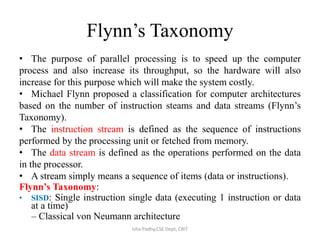
  • 1. Flynn’s Taxonomy • The purpose of parallel processing is to speed up the computer process and also increase its throughput, so the hardware will also increase for this purpose which will make the system costly. • Michael Flynn proposed a classification for computer architectures based on the number of instruction steams and data streams (Flynn’s Taxonomy). • The instruction stream is defined as the sequence of instructions performed by the processing unit or fetched from memory. • The data stream is defined as the operations performed on the data in the processor. • A stream simply means a sequence of items (data or instructions). Flynn’s Taxonomy: • SISD: Single instruction single data (executing 1 instruction or data at a time) – Classical von Neumann architecture Isha Padhy,CSE Dept, CBIT
  • 2. • SIMD: Single instruction multiple data There are no. of processing elements: no. of registers but control unit is same. All the processing elements are executing same instruction. Ex image processing , add 2 images: 2 matrix m*n, every matrix point will represent a intensity value in digitized form. same operation(add) to be performed on all the elements of the matrix. • MISD: Multiple instructions single data - Non existent, just listed for completeness. - Theoretical true because multiple operation on same data is hardly possible. • MIMD: Multiple instructions multiple data - Most common and general parallel machine - Leads to a type of computing called distributed computing. no. of independent computers , each computer is executing diff instruction ,each instruction working on diff data set. If different instructions belong to same task then each computer has to interact with each other and that can be done LAN, closely n/w. Isha Padhy,CSE Dept, CBIT
  • 3. SISD SIMD MISD MIMDIsha Padhy,CSE Dept, CBIT
  • 4. Non- pipeline process Pipeline process - Pipelining is a technique of decomposing a sequential process into sub- processes, with each sub-process being executed in a special dedicated segment that operates concurrently with all other segments. It is an implementation technique whereby multiple instructions are executed in an overlapped manner. Min aim is to increase the throughput of the processor. - This technique is efficient for applications that are going to repeat the same task on different set of data. Isha Padhy,CSE Dept, CBIT
  • 5. Non- pipeline process Pipeline process Isha Padhy,CSE Dept, CBIT
  • 6. General considerations: 4 segment pipeline • The operands pass through all the segments in a fixed sequence. • Task T is divided into sub task:t1,t2,t3, t4. • Assume there are 4 computing block S1,S2,S3,S4 is capable of executing S1(t1),S2(t2),S3(t3),S4(t4), each taking same amount of time to execute (τ) • So for completion of 4 subtask or task T in case of single instruction is 4 τ. If n no. of task, then completion time is 4n τ. • If we have identical jobs to be done, pipeline concept can be used to increase the throughput. • Once the pipeline is full, when every processing element has a job to execute, now at every τ time we can get an output. In single inst after every 4 τ we will get an output. Isha Padhy,CSE Dept, CBIT
  • 8. • if there are K stages in the pipeline, where every stage takes τ time to execute, and n jobs to be executed, - In a non-pipeline architecture: amount of time taken is nkτ. - In a pipeline architecture: (n+(k-1)) τ Ex. No. of stages=4(k) no. of sub task= 6(n), so 9 clock cycles. - In general all stages will not take equal amount of time: τ=max{τi}1 K +τl , τi :time taken by the ith stage, K: K no. of stages, τl : latching delay τ : time taken to operate, depends on which stage is taking max time. • 2 areas where pipeline organization is applicable: arithmetic pipeline, instruction pipeline. Isha Padhy,CSE Dept, CBIT
  • 9. Arithmetic Pipeline • Units are found in high speed computers for floating point operations. • Ex. 2 floating point number we r going to add, • a,b are mantissas p,q are exponents • Steps to execute: 1. Compare the exponents 2. Align the mantissa 3. Add or subtract mantissa 4. Normalize the result. • A=a*2p 0.5*103 equalize the power values: 0.005*105 B=b*2q 0.3*105 0.3*105 0.305*105 • Always after point, 0 values are removed so depending on power of 10 is reduced. ex.003*104=.3*102 Isha Padhy,CSE Dept, CBIT
  • 10. Pipeline for floating addition 1. 1st latch will take fraction and exponent part: a , p. 2nd latch will take b , q 2. Compare the exponents 10 power(p,q)-> result, depending on the result we have to normalize the fraction part(to same exponents ex 105 ) 3. Fraction selector: input a,b , result from comparator, then make right shift(.5->.005) depending between difference between p,q. 4. |p-q| will denote how many bits shift will take place. 5. No. of latches should be equal both sides( exponent and fraction) other wise time delay will lead to data loss(we will get fraction and no exponent or vice versa). 6. From exp comparator we get max exponent. 7. Leading 0 counter: gives no. of bits left shift (re -normalization of result.) 8. Now depending on leading 0’s we have to give left shift. 9. Exp subtractor: no. of left shift will be the no. that will be deducted from exponent.(ex.003*104=.3*102 ) No. of left shift= subtract that factor from exponent. 10. Final result will be d*2s. Isha Padhy,CSE Dept, CBIT
  • 11. Nt: ex. Addition of 2 linear array of floating numbers, pipeline can be used. Latches are required only when the computation speed is different in different pipeline stages. This type is called execution pipeline. s d Isha Padhy,CSE Dept, CBIT
  • 12. Instruction Pipeline • An instruction pipeline reads consecutive instructions from memory while previous instructions are getting executed in other segments. • Dividing the instruction execution across several stages ,require each stage access only a subset of CPU’s resources(ALU, Registers, Bus etc). Ideally(may change) a new instruction can be issued in every cycle. • Any instruction can be done in following steps:- - Fetch the instruction - Decode the instruction - Calculate the effective address - Fetch the operands from memory - Execute the instruction - Store the result in the proper place • Sometimes there will be difficulty in pipelining instructions because all the segments do not require same amount of time, some segments are skipped(ex in register transfers effective address calc is not required),2 segments may require to read memory same time etc. Isha Padhy,CSE Dept, CBIT
  • 13. 4 segment instruction pipeline • We assume all segments take same time. • Step 2,3 are combined, steps 5,6 can be combined and executed. We assume that we use processor registers to hold the result. • Fig 1. When an instruction is executed in segment 4, another instruction is busy fetching operand from memory in segment3. • When the instruction is program control type(a branch out of normal sequence), the pending operations in the last 2 segments are completed and all the instructions in instruction buffer is deleted. Then a new address is entered to PC. Isha Padhy,CSE Dept, CBIT
  • 15. Timing of instruction pipeline Isha Padhy,CSE Dept, CBIT -We assume that the processor has separate instruction and data memories so FI and FO can be done at same time. - No branch instruction, each segment operates on different instructions. -When DA of 3rd instruction was decoded and found that it was a branch instruction, FI of 4th instruction is halted till the branch instruction is executed. If branch is taken new instruction is send to step 7 or else normal 4th step is executed. FI: segment 1 that fetches the instruction. DA: segment 2 that decodes the instruction and calculates the effective address. FO: segment 3 that fetches the operands. EX: segment 4 that executes the instruction.
  • 16. Problems with instruction pipeline (Pipeline Hazards). • A pipeline hazard occurs when the instruction pipeline deviates at some phases, some operational conditions that do not permit the continued execution. The major pipeline hazards are described below: • Resource hazard (Resource conflict). • Data hazard (data dependency). • Branch hazard (branch difficulties). 1. Resource hazard It is caused by the access to shared memory by 2 segments at the same time. This can be resolved by using separate instruction and data memories. Isha Padhy,CSE Dept, CBIT
  • 17. • 2. Data Hazard It arises when instructions depend on the result of previous instruction but the previous instruction is not available yet. Ex. An instruction in FO segment may need to fetch an operand which is produced by previous instruction. The most common techniques used to resolve data hazard are: (a) Hardware interlock - a hardware interlock is a circuit that detects instructions whose source operands are destinations of instructions farther up in the pipeline. It then inserts enough number of clock cycles to delays the execution of such instructions. (b) Operand forwarding - This method uses a special hardware to detect conflicts in instruction execution and then avoid it by routing the data through special path between pipeline segments. for example, instead of transferring an ALU result into a destination result, the hardware checks the destination operand, and if it is needed in next instruction, it passes the result directly into ALU input, bypassing the register. c) Delayed load - It is software solution where the compiler is designed in such a way that it can detect the conflicts; re-order the instructions to delay the loading of conflicting data by inserting no operation instruction. Isha Padhy,CSE Dept, CBIT
  • 18. • 3. Branch hazard The major obstruction that a instruction pipeline is branch instructions. Such instructions can be conditional(depend on the condition, if yes branch to target inst address or next inst in sequence will be executed) or unconditional(PC is assigned the target instruction address).Computers use hardware technique to minimize this hazard. (a) Multiple streaming - It is an approach which replicates the initial portions of the pipeline and allows the pipeline to fetch both instructions(target instruction of branch and instruction next to branch), making use of two streams (branches). If condition is successful then target is selected or the next is selected. (b) Branch target buffer (BTB)- BTB is a memory present in fetch segment of an instruction. Each entry consists of address of previously executed branch instruction and their target instruction. After decoding the instruction as branch instruction it refers its own BTB, if any information of the required branch instruction is available then use it or pipeline shifts to a new instruction stream and stores the target instruction in BTB. Thus branch instructions previously used are readily available. Isha Padhy,CSE Dept, CBIT
  • 19. (c) Loop buffer - A variation of BTB. A loop buffer is a small, very-high- speed memory maintained by the instruction fetch stage of the pipeline. When a loop is detected in the program , complete instruction set is kept in this memory area along with any branches present in the loop. And this loop can be executed without disturbing the memory until loop breaks. • (d) Branch prediction - uses additional logic to predict the outcomes of a (conditional) branch before it is executed. • (e) Delayed branch - This technique is employed in most RISC processors. In this technique, compiler detects the branch instructions and re-arranges the instructions by inserting no-operation instruction after branch instructions to avoid pipeline hazards. Isha Padhy,CSE Dept, CBIT
  • 20. RISC PIPELINE • In RISC, all the instruction formats are of same length so decoding of instruction and register selection will occur at same time. Every operand is present in registers so no calculation of effective address. • The pipeline can be done in 2 or 3 segments. So the steps can be: - Fetching instruction from memory. - Executing operation in ALU. - Storing the result in destination register. • For register transfers , only 2 instructions are present load, store. • To prevent conflicts between a memory access to fetch an instruction and to load /store operand, there are 2 separate memories ,one for instruction and one for data. • RISC has ability to complete an instruction in 1 clock cycles so pipeline segments can be achieved easily, but CISC will have many segments with the longest segment taking 2 or 3 clock cycles. Isha Padhy, CSE Dept, CBIT -Fetch the instruction -Decode the instruction -Calculate the effective address -Fetch the operands from memory -Execute the instruction -Store the result in the proper place
  • 21. • RISC instruction formats: 32 bit, 31 instructions. • Addressing modes: register addressing, immediate addressing, relative to PC addressing for branch instructions. • 138 registers: 8 windows of 32 registers each(10 global, 10 local, 6 low overlapping, 6 high overlapping) • Instruction format: 32 bit: 8(7bits operation+ 1 b status bit depending on ALU oper), 5(5b to specify 1 out of 32 reg), 13 bit=0(low order of S2 specifies another source reg),13th bit=1(13 b operand), Y(relative address to jump), COND. • 31 instructions: Data manipulation, transfer, program control. • All instructions have 3 operands: 2nd operand can be a register, immediate operand,3rd register can be specified as R0(all bits 0). • LDL (R22)#150,R5 //R5<-M[R22]+150 LDL(R22)#0, R5 //R5<-M[R22] Isha Padhy,CSE Dept, CBIT Opcode Rd Rs 0 Not Used S2 Opcode Rd Rs 1 S2 Opcode COND Y 8 5 5 1 8 5 8 5 5 1 13 8 5 19 Register Mode Register imm Mode PC Relative Mode
  • 22. 3 segment Instruction pipeline Isha Padhy,CSE Dept, CBIT The instruction cycle is divided into 3 segments:- - (I) Instruction fetch: fetches the instruction from program memory and decoded, the registers needed for execution are also selected. - (A) ALU performs the operation depending on the decoded instruction. There are 3 operations that can be done by ALU. a. Data manipulation instruction. b. Evaluate the effective address for a load or store instruction(register indirect method) c. Calculates the branch address for a program control instruction. PC<-PC+Y - (E) directs the output of the ALU to any 1 destination(destination register/data memory/ branch address to PC)
  • 23. Delayed Load • LOAD : R1<- M[address 1] LOAD: R2<-M[address 2] ADD: R3<-R1+R2 STORE: M[address 3]<- R3 • For the above instructions to be pipeline: A segment in cycle 4 is using the data from R2, but the value of R2 is not a correct value as the data is not transferred from memory at that time. So to solve this problem we can insert a no- operation instruction between the 2 conflicting instruction such that a clock cycle is wasted and thus use of data loaded from memory is delayed. Isha Padhy,CSE Dept, CBIT
  • 24. Vector processing Isha Padhy,CSE Dept, CBIT In computing, a vector processor or array processor is a CPU that implements an instruction set containing instructions that operate on 1- dim arrays of data called vectors, compared to scalar processors, whose instructions operate on single data items. Vector processors have high-level operations that work on linear arrays of numbers: "vectors“ => Each result independent of previous result => long pipeline, compiler ensures no dependencies => high clock rate
  • 25. • Five basic types of vector operations: 1. V <- V Example: Complement all elements 2. S <- V Examples: Min, Max, Sum 3. V <- V x V Examples: Vector addition, multiplication, division 4. V <- V x S Examples: Multiply or add a scalar to a vector 5. S <- V x V Example: Calculate an element of a matrix • Application areas where vector processing is used: Long range weather fore-casting, biological modeling, car crash simulation, speech, image processing etc. Isha Padhy,CSE Dept, CBIT
  • 26. Vector Operations Isha Padhy,CSE Dept, CBIT • V=[V1, V2,…..Vn] row vector of length n. • The element Vi of vector V is written as V[I], I is index refers to memory address or register where the number is stored. • int a[10], b[10]; Initialize i=0 int c[10]; Read a[I], Read b[I] …. for (i = 0; i < n; i++) Store C[I]=a[I]+b[I] c[i] = a[i] + b[i]; Increment I=I+1 //pointing to next location If I<10, continue. // Vector processors have the ability to remove overhead of instruction fetch and execution in loop.
  • 27. • Instruction can be written as c(1:10)=A(1:10)+B(1:10) • Any vector instruction has: • Addition is done with pipelined floating point adder in same process as scalar. Isha Padhy,CSE Dept, CBIT
  • 28. Isha Padhy,CSE Dept, CBIT Complexity =27 operations N*N mul requires, n3 multiply- add operations. Ex C11=((c11+a11b11)+a 12b21)+a13b31. so 9*3=27 operations.
  • 29. Isha Padhy,CSE Dept, CBIT • Every inner product consists of sum of k- products C= A1B1+A2B2+….AkBk • The multiplier and adder have 4 segments pipeline.To each segment 1 mul is allowed in clock cycle, so in 1st 4 cycles: A1B1, A2B2, A3B3, A4B4 are finished and mean time the outputs of adder are all 0. • For next 4 cycles 0 is added to 1st 4 multiplications . So in next 8 cycles , A1B1 to A4B4 are in adder and A5B5 to A8B8 are in multiplier segment.At beginning of 9th cycle the output of adder A1B1 is added to A5B5, then A2b2+A6B6…. • So we get 4 sections: A1B1+A5B5+A9B9+.. +A2B2+A6B6+… +A3B3+A7B7+… +A4B4+….
  • 30. Memory Interleaving Isha Padhy,CSE Dept, CBIT - For pipelining and vector processing, memory can be required to access simultaneously by 2 sources. - The memory can be partitioned into a no. of modules connected to common address bus and data bus. - A memory module consists of memory array, its own registers. The least 2 sig bits in the address can be used to distinguish between the 4 modules and the rest bits for exact location.
  • 31. Array Processors • Suitable for scientific computations involving two dimensional matrices • An array processor has single instruction for mathematical operations, for example, SUM a, b, N, M a ─ an array base address , b ─ another vector base address, N─ the number of elements in the column vector, M ─ the number of elements in row vector • 2 types: - Attached array processor: 1. In this an auxiliary processor is attached to a general purpose computer. It enhances the performance of the host computer in specific numerical computation tasks. 2. This attachment is done by parallel processing i.e. it contains one or more pipelined floating point adders and multipliers. 3. Can be programmed by user. 4. The array processor is connected through an i/p-o/p controller to the computer. Data is received from main memory through high speed bus. Isha Padhy,CSE Dept, CBIT
  • 32. SIMD Array Processor Ex ILLIAC IV Isha Padhy,CSE Dept, CBIT
  • 34. Why use array processor Isha Padhy,CSE Dept, CBIT
  • 35. Computer arithmetic • Addition , subtraction, multiplication and division of :- 1. fixed-point(total,fraction) binary data in signed magnitude representation. 2. Fixed point binary data in signed 2’s complement representation 3. Floating point binary data 4. Binary coded decimal data(BCD) Isha Padhy,CSE Dept, CBIT
  • 36. Addition and subtraction • Negative fixed point binary numbers can be represented as: signed magnitude, signed- 1’s complement, signed 2’s complement. • This representation of negative numbers are used to represent number in registers before and after arithmetic operation. • Addition(subtraction) algorithms: - When the signs of A and B are identical(different), add(subtract) the 2 magnitudes and attach the sign of A to the result, - when different (identical), compare the magnitudes and subtract the smaller from the larger, choose the sign of the result to be same as A if A>B, or complement the sign of A if A<B. If A=B , then subtract B from A make the result sign +. - Hardware Implementation: 2 registers(Ra,Rb) to hold 2 operands, 2 flip-flops(As, Bs) to store the signs, parallel adder(A+B), a comparator circuit to compare (A>B, B>A, A=B) , 2 parallel subtractor circuits (A-B,B-A). Sign can be formed from an X-OR gate with As,Bs as inputs. This can be implemented as: - Subtraction can be done as A+2’s comp of B. - E flip-flop determines the relative magnitude of A,B - AVF holds the overflow bit when A,B are added. - M –signal=0,the B is transferred to adder, input carry is 0, so the sum=A+B. - M=1, 1’s complement of B(complementer)+A+1(input carry)= A-B Isha Padhy,CSE Dept, CBIT
  • 37. Addition and subtraction with signed- magnitude Isha Padhy,CSE Dept, CBIT
  • 38. Multiplication Algorithms • Multiplication: If the multiplier is a 1, then copy the multiplicand ,if 0 then all the bits are 0. the numbers copied down in successive lines are shifted to left by 1 position from the previous number, finally all the numbers are added. • Steps: 1. Initially the multiplicand is in B, multiplier in Q with their signs in Bs,Qs. 2. Registers A, E are cleared(A<-0,E<-0), sequence counter= number equal to number of bits of the multiplier(SC<-n-1). We assume n-bit word(operand) is transferred from memory, where magnitude=n-1 bits, 1 bit for sign. 3. Low order bit of Qn is tested, if 1, the multiplicand is added to A(0 initially).if 0 then nothing is done. Register EAQ is shifted right. Sequence counter is decremented by 1 and new value checked, if not 0 then process is repeated. 4. The partial product formed in A is shifted into Q slowly and ultimately the low order bits are in Q and MSB bits of the result in A. Isha Padhy,CSE Dept, CBIT
  • 39. Isha Padhy,CSE Dept, CBIT 10111 *10011 10111 10111 00000 . . 10111 110110101
  • 41. Booth’s Algorithm Isha Padhy,CSE Dept, CBIT -Algorithm is used for multiplying binary integers in signed 2’s compl. - mp:2p - multiply multiplicand M by 14(23+1- 21)[multiplier] - Algorithm also requires checking multiplier bits and shifting of partial product, but prior to shifting following steps may be done:
  • 43. Ex of booth algorithm • 6*2 ,6:0110 2:0010 6 in BR(multiplicand register) 2 in QR(multiplier register) Isha Padhy,CSE Dept, CBIT Q0 Qn+1 Action 0 0 RS 1 1 RS 1 0 A<-A-BR 0 1 A<-A+BR BR A QR Qn+1 SC 0110 0000 0010 0 100 00 shift 0000 0001 0 011 10 subtract shift 0000-0110 1010 1101 0001 0000 0 1 010 01 Add, shift 1101+0110 0011 0001 0000 1000 1 0 001 00 shift 0000 1100 0 000 Ex. -9(10111)*- 13(10011)
  • 44. 2 bit by 2 bit array multiplier Isha Padhy,CSE Dept, CBIT - Why AND gate: a0=1 b0=1 a0b0 will be 1 only if a0*b0=1, otherwise 0. - For j multiplier bits, k multiplicand bits, we need j*k AND gates and (j- 1) k bits adders to produce product of (j+k) bits.
  • 45. 4 bit by 3 bit array multiplier Isha Padhy,CSE Dept, CBIT
  • 46. Division • 1000)1001010(0001 001 1000 10 101 1010 - 1000 10 Isha Padhy,CSE Dept, CBIT -Shift divisor right and compare it with current dividend -If divisor is larger, shift 0 as the next bit of the quotient -If divisor is smaller, subtract to get new dividend and shift 1 as the next bit of the quotient
  • 47. Division Algorithm Isha Padhy,CSE Dept, CBIT Steps: - Divisor is in B, double length dividend is stored in A and Q. -Dividend is shifted to left and divisor is subtracted by adding 2’s complement value. - E gives the relative value of B and A. -If E=1(A>=B), I is inserted in Qn, shift left, subtract B(2’s comp of B+1) -If E=0, Qn=0, add B to restore the value of B, shift left + subtract B.
  • 48. Divide Overflow • Condition for overflow: 1. High order half bits of dividend is greater than or equal to divisor. 2. Division by 0. • Overflow condition can be checked by a flip flop called DVF. • Handling of overflow: - Check the overflow condition after every divide operation and if DVF is set then there will be branch to a subroutine which will take measures to rescale the data. - Divide stop: stop the operation of computer. - Interrupt request is sent . - Stop the program and send to user an error message explaining the reason why program is stopped. Isha Padhy,CSE Dept, CBIT
  • 50. Explanation of flow-chart • Dividend is kept in AQ, divisor in B • Sign bit of A=As, B=Bs, As XOR Bs= Qs(Both A and B are of same magnitude or not, If yes Qs=0,or Qs=1) • EA:A+B’+1 //A-B to check whether A>B(Dividend>divisor) • E=1, DVF<-1, Dividend > divisor, so hardware will not allow, DVF condition prevails. E=0, A<B, DVF<-0, so we move on to next step. For both above steps, B is added(A+B) to get back the value of A(previous step it was deducted(A-B) to check whether A>B) Step 1. E=0: 1. shl EAQ • E=0, EA<-A+B’+1(ADD B 2’s complement) • E=1, A<-A+B’+1 • E=1, Qn=1 • E=0, EA<- A+B Isha Padhy,CSE Dept, CBIT SC<-SC+1 Continue the process from step-1
  • 51. Floating –point arithmetic operations • Floating point number register consists of 2 parts: mantissa m and exponent e --- m*re • A floating point number that has a 0 in the MSB of the mantissa is said to have an underflow. To normalize the number it is necessary to shift the mantissa to the left and decrement the exponent until a nonzero digit appears in the 1st position. Ex .00345*105= .345*103 • Register configuration: same as for fixed point operation. The difference lies in the way exponents are handled. Isha Padhy,CSE Dept, CBIT
  • 52. Registers for floating point arithmetic operations • 3 registers :BR,AC,QR • All have 2 parts: mantissa(upper case letter), exponent(lower case letter) • Assumed that each floating point number has a mantissa in signed magnitude and a biased exponent(bias is no. that is added to exponent. Ex exp that ranges from -50 to 49, we consider 00 to 99 as +ve number. Positive exponents range from 99 to 50 and 49 to 00 as negative exponent) • Comparator: used to compare the +ve exponents to adjust mantissa part for normalization. • As:sign bit of A, Qs: sign bit of Q, Bs: sign bit of B., A1: 1 if the number is to normalized. • 2 parallel adder, A: mantissa Q+B, E:carry bit a: exponent b+q Isha Padhy,CSE Dept, CBIT
  • 53. Addition and subtraction Isha Padhy,CSE Dept, CBIT
  • 54. Multiplication of floating point numbers Isha Padhy,CSE Dept, CBIT
  • 55. Division of floating point numbers Isha Padhy,CSE Dept, CBIT
  • 56. BCD ADD - To add 2 BCD decimal numbers, max value for a operand allowed is 9. So 2 nos addition will be 9+9+1(carry)=19.The adder will form addition in form of binary and result will be within 19. - The binary representation should be converted to BCD form, we see till 1001 the corresponding BCD is equal but after that if we add binary 6(0110) to the binary sum converts correctly to BCD form. - The ckt detects the necessry condition to know which binary nos. are to converted to BCD. Correction is required when 1. K bit =1 2. For 1010 to 1111, k8 bit =1 3. K8 bit of 1001 and 1000 is also 1, so k8 with K4 or K2 bit =1 - We can get the boolean function C= K+Z8Z4+Z8Z2 - When C=1, add 0110 to binary sum and provide carry to next stage. Isha Padhy,CSE Dept, CBIT