In the Vector Control method of induction motors, one of the advantages of the separately excited DC motor of being able to decouple the flux control and the torque is thereby opened up. The field orientation control of induction motor allows decoupling the control of magnetic flux and the control of the torque produced by the stator current. To drive three phase squirrel cage induction motor with a constant speed, vector control technique is used. In this paper, the development of speed control system for three phase squirrel cage induction motor using a vector control method is presented and simulation for proposed system is done with the help of MATLAB SIMULINK. Soe Sandar Aung | Thet Naing Htun "Speed Control System of Induction Motor by using Vector Control Method" Published in International Journal of Trend in Scientific Research and Development (ijtsrd), ISSN: 2456-6470, Volume-3 | Issue-5 , August 2019, URL: https://www.ijtsrd.com/papers/ijtsrd27914.pdfPaper URL: https://www.ijtsrd.com/engineering/electrical-engineering/27914/speed-control-system-of-induction-motor-by-using-vector-control-method/soe-sandar-aung
2. International Journal of Trend in Scientific Research and Development (IJTSRD) @ www.ijtsrd.com eISSN: 2456-6470
@ IJTSRD | Unique Paper ID – IJTSRD27914 | Volume – 3 | Issue – 5 | July - August 2019 Page 2255
parameters used in and indirect field-oriented controller to
ensure proper operation.
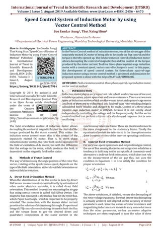
Figure.1 Indirect Field-oriented Control of Current-
regulated PWM Inverter Induction Motor Drive
III. Mathematical Model of Induction Motor
There are three main references of motion, which could be
used to model the three phase induction machineinitsthree
main regions of operation. These are stationary reference
frame for startup, the synchronous reference frame for
equilibrium motion, and the rotor reference frame for
changing speeds by acceleration or deceleration. The two
commonly employed coordinate transformations with the
induction machine are the stationary and the synchronous
referenceframe.Thesemathematical transformations,which
are known as Park Transformation, can facilitate the
understanding of the variation of mutual inductance
between the stator and the rotor under differing rotation
conditions. In this paper, the modeling is done in
synchronous reference frame where the variables appear as
DC quantities facilitating smooth control. Here, the three
phase variables (a-b-c variables) are first transformed into
stationary reference frame using Clark’s transformationand
the d-q axis variables are obtained using Park’s
transformation, there by facilitating controller design and
evaluation of transient phenomena in the drive system.
Figure 2 shows the equivalent circuit ofd-qaxes ofinduction
motor.
Figure.2 Equivalent Circuit in d-q Axes of Induction Motor
Figure.3 Three-phase to d-q Stationary Reference Frame
Transformation
Figure.4 d-q Stationary Frame to d-q Synchronous Frame
Transformation
Where P is the number of pole and Te is the electromagnetic
torque TL is load torque, J is the inertia of the rotor and
connected load B is the friction. The Simulink block of
electromagnetic torque is shown in Figure 5 and the
Simulink block of motor speed is shown in Figure 6.
Figure.5 Simulink Blocks of Electromagnetic Torque
Figure6. Simulink Blocks of Motor Speed
3. International Journal of Trend in Scientific Research and Development (IJTSRD) @ www.ijtsrd.com eISSN: 2456-6470
@ IJTSRD | Unique Paper ID – IJTSRD27914 | Volume – 3 | Issue – 5 | July - August 2019 Page 2256
IV. Propose Control System of Induction Motor
Using Vector Control Scheme
Figure.7 Overall Simulink Model of Vector Control for
Induction Motor
Figure8.Simulation Diagram for PWM Inverter
Figure.9 Simulink Model of Vector Control Block
The overall Simulink model of vector control system for
induction motor is shown in figure 7. Figure 8 is PWM
Inverter generation block and figure 9 is Vector Control
Block. For the induction motor control, the modeling and
simulation is carriedoutwithMATLAB/SIMULINKsoftware.
For the modeling 11kW, 400V induction motor is used and
parameters of induction motor are shown in table 1.
Table.1 Parameters of induction motor
Rated Power, kW 11
Rated Voltage, V 400
Rated speed, rpm 2460
Numbers of pole (p) 4 poles
Stator resistance (r1) 0.35 Ω
Stator reactance (x1) 0.88 Ω
Rotor resistance (r2) 0.4 Ω
Rotor reactance (x2) 1.67 Ω
Magnetizing reactance ( xm) 1.209 Ω
V. Result
The vector control drivefor11 kWthree-phasesquirrel-cage
inductions motor is shown in figure 7. In this drive, the
speed is set at 750 rpm and the flux reference is maintained
at 0.8. At 0.6 sec the load torque change from no-load to3.48
Nm, at 1.8 sec the load torque change from 3.49 Nm to 17.4
Nm, at 3 sec the load change from 17.4 Nm to 41.76 Nm, at
4.2 sec the load torque change from 41.76 Nm to 3.48 Nm
and at 5.4 sec the load torque change from 3.48 Nm to 0. The
resultant three-phase current of vector control of induction
motor is shown in figure 10. The load is increased at 0.6 sec,
1.8 sec, 3 sec and decreased at 4.2 sec, 5.4 sec. In this case it
seen that, when the load on the motor is increasedthemotor
currents are increased and when the load on the motor is
decreased the motor currents are decreased. At maximum
load torque (41.76 Nm), the currents are reaching to 18 A.
Figure.10 Three-phase Currents Response of Vector
Control
Figure 11 shows the rotor speed of the machine at different
load torque. This demonstrates that high dynamic
performance speed response to change in demand torque.
The sudden application of the load on the motor shaft cause
a small dip or rise in the rotor speed, which recovers quickly
resulting in zero steady state speed error. In figure 11, the
speed reaching to the desired speed at 0.2 sec and is loaded
3.48 Nm, the speed decreases to the 745 rpm and return to
the desired speed in 0.1 sec. When the load torque is
changed from 3.8 Nm to 17.4 Nm, the speed decreases to the
710 rpm and return to the desired speedin0.2sec.Whenthe
load torque is changed from 17.4 Nm to 41.76 Nm, thespeed
decreases till 690 rpm and return to the desired speed in0.3
sec. When the load torque is changed from 41.76 Nm to 3.48
Nm, the speed increases till 850 rpm and return to the
desired speed in 0.3 sec. When the load torque is changed
from 3.8 Nm to 0 for no load, the speed increases to the 755
rpm and return to the desired speed in 0.1 sec.It is seemthat
the speed responses were smooth at different load torques
and the speed follow perfectly the speed reference. The
speed response is fast, accurate and gives a good result for
variable load torque of induction motor.
4. International Journal of Trend in Scientific Research and Development (IJTSRD) @ www.ijtsrd.com eISSN: 2456-6470
@ IJTSRD | Unique Paper ID – IJTSRD27914 | Volume – 3 | Issue – 5 | July - August 2019 Page 2257
Figure.11 Speed Response of Vector Control
Figure 12 shows the resultant torque response of vector
control of three-phase squirrel-cage induction motor.
Figure.12 Torque Response of Vector Control
An increase and decrease of the load on the shaft of the
motor are developing increase and decrease of
electromagnetic torque. When the load torque is suddenly
changed, there is the spike torque (it reaches 49 Nm) that
carries more current. According to the switchingpulsethree
level bridge switches turned on and off simultaneous, step
input is given for as mechanical input. In this method, the
deviation of the speed due to the load is so small and speed
returns to the desired speed in a very small time.
VI. Conclusion
This paper presents the speed control of induction motor
using vector control method was implemented using
MATLAB/ SIMULINK. In vector control system,a closedloop
speed control technique is used for induction motor. The
induction motor control system based on vector control
method produces the best speed error and no steady state
error. Therefore, the results ofvectorcontrolsystemare able
to perfect the stability of the speed variation and less error
speed for induction motor.
References
[1] Rakesh, P.: AC Induction Motor Fundamental, AN
887Microchip Technology Inc., (2003).
[2] Krishnan, R.: Electric Motor Drives Modeling, Analysis
and Control, Prentice Hall, Inc., Upper Saddle River,
New Jersey 07458, (2001).
[3] Sprecher, S. A. G. R. A.: Application Basics of Operation
of Three-phase Induction Motors, (1996).
[4] Ashfaq, A.: Power Electronics for Technology, Hall
International, Inc., International Edition, (1999).
[5] Ong, C. M.: Dynamic simulation of electric machinery:
using MATLAB/SIMULINK, vol. 5, Prentice Hall PTR
Upper Saddle River, NJ, (1998).
[6] Chee-Mun, O.: DynamicSimulationof ElectricMachinery
using Matlab/Simulink, A Simon and Schuster
Company, Upper Saddle River, New Jersey, (1997).
[7] Wang, X., Yang, Y. and Liu, W.: Simulation of vector
controlled adjustable speed System of induction motor
based on Simulink, pp. 2563-2566,(2011).