SlideShare uma empresa Scribd logo
1 de 9
Baixar para ler offline
International Journal of Recent advances in Mechanical Engineering (IJMECH) Vol.4, No.4, November 2015
DOI : 10.14810/ijmech.2015.4406 67
COMPARATIVE STUDY OF DIFFERENT
COMBINED CYCLE POWER PLANT
SCHEMES
Nikhil Dev and Rajesh Attri
Department of Mechanical Engineering, YMCA University of Science and
Technology, Faridabad, Haryana, India
ABSTRACT
Combined Cycle Power Plants (CCPPs) are imperative for power generation with the capability for
deciphering power shortage during peak and off peak hours. To perk up the recital of the plant, foremost
locations of exergy losses are to be identified and analyzed. In the present work, exergetic analysis of a
CCPP is carried out using the computer programming tool Engineering Equation Solver (EES). The effects
of overall pressure ratio and turbine inlet temperature on the exergy destruction in the CPR are
investigated. The results obtained are compared with that of simple gas turbine cycle power plant. During
real time operation of CCPP exergy destruction in different components is associated with change in
overall pressure ratio and turbine inlet temperature (TIT). Out of the total exergy destruction in the cycle it
is the combustion chamber (CC) which is responsible for the maximum exergy destruction. Nearly 60% of
the total exergy is destroyed in CC. Results clearly show that with increase in complicacy of the power
plant structure, irreversibility of the processes can be improved.
KEYWORDS
First-law, Second-law, Exergy Destruction, Gas Turbine Cycle, Combined Cycle Power Plant, Waste Heat
Recovery Boiler.
1. INTRODUCTION
India is swift developing economy, with a need for independent and reliable supply of electricity
and to be a power sufficient country is one of its prime concerns. At present total installed
capacity of electricity generation in India by large scale power plants is 132,110.21 MW and per
capita electricity consumption in 2005-06 was about 631 KWH as calculated by CEA (Central
Electricity Authority). This electric power consumption may be compared with other developed
countries. Such as in U.S.A. per capita consumption of electric power is 13,338 KWH. The NEP
(National Electricity Policy) decided that to make the country a developed country it is required
the per capita consumption of electricity should be over 1000 units by 2012. Therefore, to achieve
the objective of developed nation, large number of new power plant erection projects are
currently in progress.
Power plants are numerous nature and out of these power plants TPP (thermal power plants)
generates 64.7% of the total installed electricity power generation capacity. Because of their
higher efficiency and reduced pollution emission gas turbine and CCPPs are becoming more and
more attractive. India is spending a great amount of money to import the fuels, alternatively it
could be used the in the development and growth of our country. In order to reduce power
International Journal of Recent advances in Mechanical Engineering (IJMECH) Vol.4, No.4, November 2015
68
shortage efforts are required to improve the performance of existing plants. The present work is
concentrated on determination of the exergy destruction of each component of the CCPP, and
comparison of exergy destruction in exhaust gas and each component of the plant by varying
overall CPR and turbine inlet temperature (TIT).
In recent times, exergy analysis has been used by scores of researchers for analysis of thermal
systems, especially for power plants (Caton, 2000). Exergetic analysis is a part of thermodynamic
analysis and it is based upon the second law of thermodynamics. Exergetic analysis takes care of
energy, exergy and mass balance across each component. Therefore, with the help of this analysis
it is possible to determine the magnitude of exergy and energy losses in different components.
Exergetic analysis is based upon the entropy generation and it is stated in thermodynamics that
every real time process increases the entropy of the universe. There are some real time processes
which are responsible for entropy generation or exergy destruction. Dev et al (2012) stressed that
it is the ambient temperature which decides the availability.
In literature (Dev et al., 2013a) exergy is defined as maximum possible work potential of a
thermal system w.r.t. the ambient environment being considered as the datum state. Any flow
stream with a temperature higher or lower than ambient is capable of performing some useful
work. The potential of work is further dependent upon the difference in between system and
surrounding. In a system entropy generation is due to heat transfer through finite temperature
difference (Dev et al., 2013a), chemical reaction (Dev et al., 2013b), mechanical friction (Dev et
al., 2013c), mixing of fluids at different temperature (Dev et al., 2013a) and vibration (Dev et al.,
2013b). In a CCPP chemical reaction in between air and fuel takes place in CC. The potential of
chemical reaction and exergy destruction is based upon the Gibbs free energy. Friction is present
in flow path due to surface tension of fluids (Dev et al., 2015).
In the literature (Dev et al., 2014a; 2014b) it is also reported that reliability is also one of the most
important parameter for the performance evaluation of the combined and cogeneration cycle
power plants. One approach named as Graph Theoretic Approach (GTA) was used for the
reliability analysis. This approach was extended further for the efficiency analysis also (Dev et
al., 2015). The results obtained with that methodology were in comparison to the results obtained
with exergetic analysis.
Butcher and Reddy (2007) carried out 2nd
law analysis of a WHRB (waste heat recovery boiler)
for different design and operating parameters. WHRB is used for steam generation in different
industries. Therefore, it is required to analyse its performance. The temperature profiles across
WHRB, work output, 2nd
law efficiency and entropy generation were the main parameters to be
analysed. In literature many computational techniques are suggested for the gas turbine (GT)
analysis. Ahmadi and Dincer (2011) used Non-dominated Sorting Genetic Algorithm (NSGA-II)
for efficiency and multi-objective optimization of a GT power plant. The results were to improve
the cycle performance. Khaliq and Kaushik (2004) analysed performance of a GT cogeneration
system using exergetic analysis. Second law analysis was found to be useful for improving the
cycle performance. In another work Kotowicz and Bartela (2010) considered the more than one
parameters for the performance analysis. They carried out thermo-economic analysis by using
genetic algorithm based optimization programme. Poma et al. (2010) also used thermal and
economic based design optimization to improve thermal system. Woudstra et al. (2010) and
Regulagadda et al. (2010) conducted first and second law analysis for a coal-fired power plant. In
the present analysis exergetic analysis of the CCPP system shown in Figure 1 is carried out for
different operating parameters.
International Journal of Recent advances in Mechanical Engineering (IJMECH) Vol.4, No.4, November 2015
69
2. CCPP SYSTEM DESCRIPTION
In the Figure 1 schematic diagram of a GT based CCPP with inlet air cooling and evaporative
after cooling of the compressor discharge is represented. Ambient air is filtered, cooled and
humidified in the air filter (AF), air humidifier (AH1) before it counter passes the inlet air to the
low-pressure compressor (LPC) in the air cooler (AC), cooling the inlet air. Air at 3 is cooled to a
temperature that is close to the wet bulb temperature at 1. Compressed air from the low pressure
compressor at 4 is cooled to 5 in an indirect intercooler using ambient humidified air that is
humidified in the air humidifier (AH2) and has a lower temperature than ambient temperature.
This cooled air enters the high-pressure compressor (HPC) and is compressed from state 5 to state
6. The outlet air of HPC at 6 is heated in heat exchanger with the exhaust flue gas coming out
from turbine. Ambient air at point 6 enters the regenerative type heat exchanger (HE), and it
exchanges heat with power turbine (PT). Afterward exhaust at point 11 is heated at point 7 after
gaining heat and it is supplied to CC where fuel i.e. CNG is burned, producing hot gases at point
8. The hot flue gases are expanded at point 9 in the high-pressure turbine (HPT) and achieve
lower pressure and temperature before re-combusted in the re-heater, after which the reheat flue
gases are expands through a PT to drive air compressor and turbo-generator. Part of the heat of
hot exhaust gas is used in the HE, and part of this heat is utilized in the WHRB to generate steam,
and hence to produce the process heat.
Fig. 1. Schematic line diagram of CCPP for the analysis
International Journal of Recent advances in Mechanical Engineering (IJMECH) Vol.4, No.4, November 2015
70
3. MATHEMATICAL MODEL
Exergy analysis is the combination of the first and second laws of thermodynamics to evaluate
the efficiencies of processes and devices. If the system operates in a steady-state, steady flow
condition and all the nonreacting gases are arbitrarily assigned as zero thermo-mechanical
enthalpy, entropy, and exergy at the condition of ambient pressure and temperature regardless of
their chemical composition, then the entropy of mixing different gaseous components can be
neglected, and the general exergy-balance equation is given by:
. . . . .
1
( )
n
W Q D
i in out
E E i me me E
=
= + − −∑ ∑ ∑ (1)
For single stream flow,
. . . . .
( )W Q in out DE E me me me= + − − (2)
The mathematical equations for different components of the CCPP are tabulated in Table 1.
Table 1. The exergy destruction rate equations for plant components
Components Exergy Destruction Rate
Air Compressor
,D AC in out ACe e e W= − + &
Combustion Chamber ,D CC in f oute e e e= + −
Gas Turbine
, ( )D GT in out GTe e e W= − − &
Heat Exchanger
, m ( ) m ( )D HE air ai ao gas gi goe e e e e= − + −
WHRB , m ( ) m ( )D WHRB gas gin gout w wout wine e e e e= − − −
Air Filter , ( )D AF a ai aoe m e e= −
Air Humidifier ,D AH ai ai w w ao aoe m e m e m e= + −
Steam Turbine , ( )D ST s win wout STe m e e W= − −
Feed Water Heater First , 1 1 14 1 20 21( )D FWH s s s se m e m m e m e= + − −
Feed Water Heater Second , 2 2 15 1 2 18 1 19( ) ( )D FWH s s s s s se m e m m m e m m e= + − − − −
Condenser , 1( )( ) ( )D COND s s win wout cw cwin cwoute m m e e m e e= − − + −
Pump , ( )D P P s win woute W m e e= + −
International Journal of Recent advances in Mechanical Engineering (IJMECH) Vol.4, No.4, November 2015
71
4. RESULTS AND DISCUSSION
In this work, the dependencies of first-law efficiency second-law efficiency and power-to-heat
ratio (PHR) on the operating parameters: pressure ratio (rp) and turbine inlet temperature (TIT) is
examined with energy and exergy balance across each component of the CCPP represented in
Figure 1.
Table 2. Effect of CPR on efficiency and heat rate of the proposed CCPP and simple GT cycle
Pressure
Ratio
Ist
law
efficiency of
gas turbine
(%)
IInd
law
efficiency of
gas turbine
(%)
Ist
law
efficiency
of CCPP
(%)
IInd
law
efficiency
of CCPP
(%)
Power to
heat ratio
12 51.3 50.8 54.5 51 14.2
20 52.1 51.1 56.2 51.8 12.8
28 52.3 51.4 57 52 11.2
36 52.4 51.5 57.4 52.1 10.1
44 52.1 51 56.8 52 9.6
52 52 50.5 56.3 51.9 8.9
Table 2 shows the variation of PHR, first law efficiency, and second-law efficiency for the
proposed CCPP and simple gas turbine cycle with variation in compressor CPR from 12 to 52 at
TIT=1600 K and RH=60%. As the CPR rp augment the compressor work is increased due to
higher aerodynamic resistance forces. It results in raising the temperature at the compressor outlet
due to absorption of higher work by the air. Air compressor and gas turbine are interconnected
and interdependencies is in such a manner that both energy absorbed by air compressor and work
generated by gas turbine are increased. Net result is dependent upon the increase in TIT also, if
possible. Higher flow of the air is adjusted with the inlet guide vanes with increase in
compression ratio. All the components of the cycle are interdependent. Therefore, as rp increases
the air temperature at the creek of HE decreases, that reduces the facility of HE due to lesser
amount of heat transfer. Hence, the flue gas temperature at HE outlet is augmented. As rp
increases the power-to-heat ratio decreases, since at much higher CPR the process heat increases
significantly. As the CPR increases, it is observed that air temperature at the inlet of the
combustion chamber decreases due to decrease in capacity of the HE, domino effect in increasing
the heat added. The ratio of net work output to the heat added represents the first-law efficiency
of the cycle. Hence, as rp increases, the first-law and second law efficiencies of the CCPP is
strong function at rp =36 with the values of 57.4% and 52.1% respectively (Table 2). Results
obtained are in line with the available in literature. Additional increase in rp reduces the
efficiencies significantly because, at much higher CPRs, air mass flow rate is to be increased to
fulfill the net requirement of work. Increase in air flow rate at compressor inlet increases fuel
addition in combustion chamber.
International Journal of Recent advances in Mechanical Engineering (IJMECH) Vol.4, No.4, November 2015
72
Table 3. Effect of TIT on efficiency and heat rate of the proposed CCPP and simple GT cycle
TIT (K) Ist law
efficiency of gas
turbine (%)
IInd law
efficiency of
gas turbine
(%)
Ist law
efficiency of
CCPP (%)
IInd law
efficiency
of CCPP
(%)
Power to
heat ratio
1300 44.2 44 47 44.1 23.1
1400 47.1 46.9 50.8 47 16.3
1500 49.2 49 53.9 49.1 12.2
1600 51.4 51.2 57 51.3 11.1
1700 53.2 53 59.7 53.1 9.7
1800 54.3 54.1 62 54.2 8.5
1900 56.2 56.1 64.8 56.2 8
Table 3 represents the deviation of the first-law, second-law efficiency, and PHR with the
alteration in turbine inlet temperature at rp =36 and RH=60% for the proposed CCPP and simple
gas turbine cycle. TIT is one of the most important design parameter. Its limiting value is
dependent upon the thermal stress bearing capacity of gas turbine blade material. First stage
turbine blades are more affected with the flue gas temperature than higher stage. Generally
compressor of the gas turbine cycle is with seventeen stages of compression aerodynamic and gas
turbine is with three stages of expansion. For a designed CPR and ambient relative humidity, the
first-law and second-law efficiencies are added up due to better utilization of waste heat and
increase in efficiency of gas turbine cycle. The increase in designed value of TIT enhances the
heat transfer rate by absorbing greater heat from turbine exhaust in the heat exchanger, and hence
the temperature of air inlet to the combustion chamber would increase, which in turn would
increase the mean temperature of heat addition that leads to reduction of the cycle heat addition.
Therefore, cycle efficiency increases with an increase in TIT. But the power-to-heat ratio
decreases noticeably for the reason that increase in generation of process heat is greater than the
electric power output at higher TIT (Table 3).
Table 4. Results of CPR on exergy destruction in different components of the cycle for TIT = 1600 K, φ =
60%, Patm = 1 bar, Tatm = 298 K
pr ,D LPEe
(kJ/kg
)
,D Ie
(kJ/kg
)
,D HPCe
(kJ/kg
)
,D HEe
(kJ/kg)
,D CCe
(kJ/kg
)
,D HPTe
(kJ/kg
)
,D RHe
(kJ/kg)
,D PTe
(kJ/kg
)
,D WHRBe
(kJ/kg
)
12 13.43 5.57 11.01 63.14 182.3 21.81 129.8 23.21 9.95
20 14.89 7.64 13.13 60.07 204.2 27.69 161.4 27.32 13.61
28 14.73 9.47 14.27 51.53 218 29.83 184.9 32.51 15.32
36 15.69 10.83 14.93 41.27 228 35.17 198.7 32.58 17.48
44 15.97 11.79 15.21 36.76 235.7 36.15 209.5 34.67 22.18
52 17.82 12.63 15.72 35.21 242.1 43.32 218.5 40.17 22.17
Table 4 gives an idea about the exergy destruction in each component of CCPP with the change
in overall cycle pressure ratio (CPR) for TIT=1600 K and RH=60%. Results in the Table 4
represents exergy destruction in the combustion process and it is found that combustion process
dominates the exergy destruction in CCPP, as expected; it represents over 60% of the total exergy
destruction in the overall system. The exergy destruction in the regenerative HE is next in the
International Journal of Recent advances in Mechanical Engineering (IJMECH) Vol.4, No.4, November 2015
73
line. As CPR increases, the exergy destruction in the CC and re-heater increases significantly.
This is because the increase in CPR implies higher combustion pressure, which leads to larger
destruction. As CPR increases the temperature at the inlet of the intercooler increases. Thus, the
temperature gradient for heat transfer in it increases with higher CPR. This explains more exergy
destruction in the intercooler for higher CPR. On the other hand, the exergy destruction in the
regenerative HE decreases as the CPR increases. This is because the higher CPR consequences in
the lower power turbine egress temperature as well as higher temperature at the inlet of the
WHRB. As a result, the exergy destruction in the WHRB increases with higher CPR. As CPR
increases, the exergy destruction in WH decreases because the gas temperature at the exit of the
WHRB decreases for a given PP (pinch point) temperature. At a given TIT, as the CPR increases
the exergy destruction in the compressor and turbine increases. The exergy destruction in AH and
AC are constant because at all CPR it has been used for the same working condition. The exergy
destruction in the evaporative after cooler increases as CPR increases.
Table 5. Effect of variation of TIT on exergy destruction in different components of the cycle for pr = 36,
φ = 60%, Patm = 1 bar, Tatm = 298 K
TIT
(K)
,D LPEe
(kJ/kg
)
,D Ie
(kJ/k
g)
,D HPCe
(kJ/k
g)
,D HEe
(kJ/k
g)
,D CCe
(kJ/k
g)
,D HPTe
(kJ/kg
)
,D RHe
(kJ/k
g)
,D PTe
(kJ/k
g)
,D WHRBe
(kJ/k
g)
130
0
16.1 10.73 14.93 26.41 208 35.32 189.2 29.86 6.13
140
0
16.1 10.73 14.93 37.23 215.3 35.67 192.6 29.91 10.18
150
0
16.1 10.73 14.93 39.71 221.9 35.42 195.7 31.83 13.12
160
0
16.1 10.73 14.93 43.62 228 35.33 198.7 31.94 15.67
170
0
16.1 10.73 14.93 53.74 233.7 35.36 201.5 33.41 20.96
180
0
16.1 10.73 14.93 59.13 239.1 35.72 204.3 34.24 25.27
190
0
16.1 10.73 14.93 64.65 244.3 35.83 207.2 31.78 29.96
Results in Table 5 shows the disparity of exergy obliteration in every constituent of CCPP with
the alteration in TIT at rp =36 and RH=60%. TIT is very much dependent upon the turbine blade
material. For the higher cycle efficiency it is desired that TIT should be as high as possible. For
higher TIT exergy destruction in the regenerative HE increases because the heat-transfer
temperature gradient in it is also increased. It is discussed earlier that higher is the temperature
difference amongst fluids more exergy is wasted. Constant heat transfer across higher
temperature leads to higher exergy destruction in comparison to lower temperature gradient. It is
due to higher degradation in energy quality. The exergy destruction in the CC and RH also
increases because the logarithmic mean combustion temperature for the whole cycle increases.
The exergy destruction in the WHRB increases because the temperature variation between the
two heat exchanging fluids (flue gas and steam) increases, and for the designed CPR, more steam
is generated by the WHRB with the higher TIT, which produces larger process heat. With
increase in TIT the exergy destruction in WH decreases as the gas temperature at the exit of the
WHRB decreases for a given pinch point temperature. The exergy destructions in AH, AC, EC,
International Journal of Recent advances in Mechanical Engineering (IJMECH) Vol.4, No.4, November 2015
74
intercooler, AC, and power turbines are also shown in Table 5 and are constant. Again, CC and
reheater are found to be a major source of irreversibility.
5. CONCLUSION
The proposed CCPP in the present work is more complex than the simple cycle gas turbine cycle.
It will increase the cost of installation and operation. For the life time cycle cost analysis
represents that major part of it is due to fuel cost. Therefore, increased efficiency of the proposed
CCPP will compensate for the installation and operation cost. Exergy analysis gives better insight
into causes of cycle inefficiencies. Therefore, it is recommended to carry out energy and exergy
analysis of a CCPP for the better understanding of the system.
Nomenclature
E

Exergy rate (kJ/s)
LHV Lower Heating Value
R Gas constant (kJ/kg K)
T Absolute temperature (K)
TP Process heat temperature (°C)
W Work (kJ/kg (dry air))
cp Specific heat at constant pressure (kJ/kg K)
cv Specific heat at constant volume (kJ/kg K)
e Specific exergy (kJ/kg (dry air))
eP Specific exergy associated with process heat (kJ/kg)
gr Gibbs function of fuel (kJ/kg)
h Enthalpy (kJ/kg (dry air))
hf Enthalpy of saturated water at process steam pressure
hg Enthalpy of saturated vapor at process steam pressure
m Mass (kg)
n Number of moles
p Pressure (bar)
Qp Process heat (kJ/kg (dry air))
rp Compression ratio
s Entropy (kJ/kg K)
t Temperature (°C)
v Specific volume (m3
/kg)
Greek Symbols
ω Humidity ratio (kg of water vapor per kg of dry air)
φ Relative humidity (%)
ε Effectiveness (%)
η Efficiency (%)
γ Specific heat ratio
Subscripts
AC Air compressor
CC Combustion chamber
D Destruction
GT Gas Turbine
P Product
International Journal of Recent advances in Mechanical Engineering (IJMECH) Vol.4, No.4, November 2015
75
Q Heat
R Regenerator
SG Steam Generator
W Work
a Ambient air
av Average
f Fuel
g Gas
i Inlet
l Liquid
o Outlet
sat Saturated
v Water vapor
w Water
1,2,3,… State points in the cycle
REFERENCES
[1] Ahmadi P., Dincer I., (2011). Thermodynamic and exergoenvironmental analyses, and multi-
objective optimization of a gas turbine power plant. Applied Thermal Engineering. 31, 2529-2540.
[2] Butcher, C. J., Reddy, B. V. (2007). Second law analysis of a waste heat recovery based power
generation system. International Journal of Heat and Mass Transfer. 50, 2355-2363.
[3] Caton, J. A. (2000). A review of investigations using second law of thermodynamics to study internal
combustion engines. SAE 2000-01-1081.
[4] Dev, N., Attri, R., Goyal G. K., Kumar, N. (2013a). Exergetic Analysis of Combined Cycle Power
Plant with Single Steam Extraction. ASME Gas Turbine India Conference, Bangalore.
[5] Dev, N., Attri, R., Goyal G. K., Kumar, N. (2013b) Graph Theoretic Analysis of Advance Combined
Cycle Power Plants Alternatives with Latest Gas Turbines. ASME Gas Turbine India Conference,
Bangalore.
[6] Dev, N., Attri, R., Sharma, V., Kumar, K. (2013c). Economic analysis of a cogeneration cycle power
plant. International Journal of Management and Behavioural Sciences. 4, 184-189.
[7] Dev, N., Attri, R. (2013). System modelling and analysis of a Gas turbine power plant using graph
theoretic approach. International Journal of Energy, Environment and Economics. 21(1), 21-33.
[8] Dev, N., Samsher, Kachhwaha, S. S., Attri, R. (2012). GTA based frame work for evaluating the role
of design parameters in Cogeneration Cycle Power plant efficiency. Ain Shames Engineering Journal.
4(2), 273-284.
[9] Dev N, Samsher, Kachhwaha SS and Attri R (2014a). Development of Reliability Index for
Combined Cycle Power Plant using graph theoretic approach. Ain Shams Engineering Journal. 5,
193–203.
[10] Dev N, Samsher, Kachhwaha SS and Attri R, (2014b). Development of Reliability Index for
Cogeneration Cycle Power Plant Using Graph Theoretic approach. International Journal of Systems
Assurance Engineering and Management. DOI 10.1007/s13198-014-0235-4.
[11] Dev N, Samsher, Kachhwaha SS and Attri R. (2015). GTA Modelling of combined cycle power plant
efficiency analysis. Ain Shams Engineering Journal. vol 6 (1), 217-237.
[12] Khaliq, A., Kaushik, S. C. (2004). Thermodynamic performance evaluation of combustion gas turbine
cogeneration system with reheat. Applied Thermal Engineering. 24, 1785-1795.
[13] Kotowicz, J., Bartela, L. (2010). The influence of economic parameters on the optimal values of the
design variables of a combined cycle plant. Energy. 35, 911-919.
[14] Poma, C., Verda, V., Consonni, S. (2010). Design and performance evaluation of a waste-to-energy
plant integrated with a combined cycle. Energy. 35, 786-793.
[15] Regulagadda, P., Dincer, I., Naterer, G. F. (2010). Exergy analysis of a thermal power plant with
measured boiler and turbine losses. Applied Thermal Engineering. 30, 970-976.
[16] Woudstra, N., Woudstra, T., Pirone, A., Van der Stelt, T. (2010). Thermodynamic evaluation of
combined cycle plants. Energy Conversation Management. 51, 1099-1110.

Mais conteúdo relacionado

Mais procurados

8th sem project review
8th sem project review8th sem project review
8th sem project review
Ankush Doshi
 

Mais procurados (19)

OPTIMIZATION OF A TURBINE USED IN COAL FIRED THERMAL POWER PLANTS BASED ON IN...
OPTIMIZATION OF A TURBINE USED IN COAL FIRED THERMAL POWER PLANTS BASED ON IN...OPTIMIZATION OF A TURBINE USED IN COAL FIRED THERMAL POWER PLANTS BASED ON IN...
OPTIMIZATION OF A TURBINE USED IN COAL FIRED THERMAL POWER PLANTS BASED ON IN...
 
Exergy analysis and igcc plant technology to improve the efficiency and to re...
Exergy analysis and igcc plant technology to improve the efficiency and to re...Exergy analysis and igcc plant technology to improve the efficiency and to re...
Exergy analysis and igcc plant technology to improve the efficiency and to re...
 
Fatigue Analysis of Acetylene converter reactor
Fatigue Analysis of Acetylene converter reactorFatigue Analysis of Acetylene converter reactor
Fatigue Analysis of Acetylene converter reactor
 
Enhancing the Performance of 75mw Steam Power Plant with Second Law Efficienc...
Enhancing the Performance of 75mw Steam Power Plant with Second Law Efficienc...Enhancing the Performance of 75mw Steam Power Plant with Second Law Efficienc...
Enhancing the Performance of 75mw Steam Power Plant with Second Law Efficienc...
 
IRJET- Energy and Exergy Analysis of Multiple Extraction Cum Condensing Stea...
IRJET-	 Energy and Exergy Analysis of Multiple Extraction Cum Condensing Stea...IRJET-	 Energy and Exergy Analysis of Multiple Extraction Cum Condensing Stea...
IRJET- Energy and Exergy Analysis of Multiple Extraction Cum Condensing Stea...
 
IRJET - Performance Evaluation and Parametric Study of Basic and Reheated Coo...
IRJET - Performance Evaluation and Parametric Study of Basic and Reheated Coo...IRJET - Performance Evaluation and Parametric Study of Basic and Reheated Coo...
IRJET - Performance Evaluation and Parametric Study of Basic and Reheated Coo...
 
Energy and Exergy Analysis of a Country Sectors - Advanced Thermodynamics
Energy and Exergy Analysis of a Country Sectors - Advanced ThermodynamicsEnergy and Exergy Analysis of a Country Sectors - Advanced Thermodynamics
Energy and Exergy Analysis of a Country Sectors - Advanced Thermodynamics
 
01_A Study of Heat Exchanger Produces Hot Water from Air Conditioning Incorp...
01_A Study of Heat Exchanger Produces Hot Water from Air Conditioning  Incorp...01_A Study of Heat Exchanger Produces Hot Water from Air Conditioning  Incorp...
01_A Study of Heat Exchanger Produces Hot Water from Air Conditioning Incorp...
 
THERMODYNAMIC ANALYSIS OF YEAR ROUND AIR CONDITIONING SYSTEM FOR VARIABLE WET...
THERMODYNAMIC ANALYSIS OF YEAR ROUND AIR CONDITIONING SYSTEM FOR VARIABLE WET...THERMODYNAMIC ANALYSIS OF YEAR ROUND AIR CONDITIONING SYSTEM FOR VARIABLE WET...
THERMODYNAMIC ANALYSIS OF YEAR ROUND AIR CONDITIONING SYSTEM FOR VARIABLE WET...
 
Combined heat and power - optimal power flow based on thermodynamic model wit...
Combined heat and power - optimal power flow based on thermodynamic model wit...Combined heat and power - optimal power flow based on thermodynamic model wit...
Combined heat and power - optimal power flow based on thermodynamic model wit...
 
Performance analysis of partially covered photovoltaic thermal (pvt) water co...
Performance analysis of partially covered photovoltaic thermal (pvt) water co...Performance analysis of partially covered photovoltaic thermal (pvt) water co...
Performance analysis of partially covered photovoltaic thermal (pvt) water co...
 
B03501007026
B03501007026B03501007026
B03501007026
 
8th sem project review
8th sem project review8th sem project review
8th sem project review
 
02 GTP-14-1384
02 GTP-14-138402 GTP-14-1384
02 GTP-14-1384
 
Analysis of Process Parameters to Improve Power Plant Efficiency
Analysis of Process Parameters to Improve Power Plant EfficiencyAnalysis of Process Parameters to Improve Power Plant Efficiency
Analysis of Process Parameters to Improve Power Plant Efficiency
 
Final report
Final reportFinal report
Final report
 
EXPERIMENTAL AND NUMERICAL STUDY OF A MICRO-COGENERATION STIRLING ENGINE FOR ...
EXPERIMENTAL AND NUMERICAL STUDY OF A MICRO-COGENERATION STIRLING ENGINE FOR ...EXPERIMENTAL AND NUMERICAL STUDY OF A MICRO-COGENERATION STIRLING ENGINE FOR ...
EXPERIMENTAL AND NUMERICAL STUDY OF A MICRO-COGENERATION STIRLING ENGINE FOR ...
 
Gas turbine exergy analysis
Gas turbine exergy analysisGas turbine exergy analysis
Gas turbine exergy analysis
 
Brain emotional learning based intelligent controller and its application to ...
Brain emotional learning based intelligent controller and its application to ...Brain emotional learning based intelligent controller and its application to ...
Brain emotional learning based intelligent controller and its application to ...
 

Destaque

13 dasar internet
13 dasar internet13 dasar internet
13 dasar internet
teddyhadia
 
PREDICTIONS AT THE BLOW END OF THE LD-KGC CONVERTER BY A SEMI-DYNAMIC CONTROL...
PREDICTIONS AT THE BLOW END OF THE LD-KGC CONVERTER BY A SEMI-DYNAMIC CONTROL...PREDICTIONS AT THE BLOW END OF THE LD-KGC CONVERTER BY A SEMI-DYNAMIC CONTROL...
PREDICTIONS AT THE BLOW END OF THE LD-KGC CONVERTER BY A SEMI-DYNAMIC CONTROL...
ijmech
 
tcStatistical and regression analysis of vibration of carbon steel cutting to...
tcStatistical and regression analysis of vibration of carbon steel cutting to...tcStatistical and regression analysis of vibration of carbon steel cutting to...
tcStatistical and regression analysis of vibration of carbon steel cutting to...
ijmech
 

Destaque (20)

13 dasar internet
13 dasar internet13 dasar internet
13 dasar internet
 
EFFECT OF PROCESS PARAMETERS ON SURFACE ROUGHNESS OF NICKEL BASED ALLOYS IN WEDM
EFFECT OF PROCESS PARAMETERS ON SURFACE ROUGHNESS OF NICKEL BASED ALLOYS IN WEDMEFFECT OF PROCESS PARAMETERS ON SURFACE ROUGHNESS OF NICKEL BASED ALLOYS IN WEDM
EFFECT OF PROCESS PARAMETERS ON SURFACE ROUGHNESS OF NICKEL BASED ALLOYS IN WEDM
 
Comparison of fuzzy logic and neural network for modelling surface roughness ...
Comparison of fuzzy logic and neural network for modelling surface roughness ...Comparison of fuzzy logic and neural network for modelling surface roughness ...
Comparison of fuzzy logic and neural network for modelling surface roughness ...
 
THE EFFECT OF GEOMETRICAL PARAMETERS ON HEAT TRANSFER AND HYDRO DYNAMICAL CHA...
THE EFFECT OF GEOMETRICAL PARAMETERS ON HEAT TRANSFER AND HYDRO DYNAMICAL CHA...THE EFFECT OF GEOMETRICAL PARAMETERS ON HEAT TRANSFER AND HYDRO DYNAMICAL CHA...
THE EFFECT OF GEOMETRICAL PARAMETERS ON HEAT TRANSFER AND HYDRO DYNAMICAL CHA...
 
techDynamic characteristics and stability of cylindrical textured journal bea...
techDynamic characteristics and stability of cylindrical textured journal bea...techDynamic characteristics and stability of cylindrical textured journal bea...
techDynamic characteristics and stability of cylindrical textured journal bea...
 
USAGE BASED COST ALLOCATION TECHNIQUE FOR EHV NETWORKS USING NON-LINEAR UTILI...
USAGE BASED COST ALLOCATION TECHNIQUE FOR EHV NETWORKS USING NON-LINEAR UTILI...USAGE BASED COST ALLOCATION TECHNIQUE FOR EHV NETWORKS USING NON-LINEAR UTILI...
USAGE BASED COST ALLOCATION TECHNIQUE FOR EHV NETWORKS USING NON-LINEAR UTILI...
 
Design of quick connect disconnect hydraulic coupling
Design of quick connect disconnect hydraulic couplingDesign of quick connect disconnect hydraulic coupling
Design of quick connect disconnect hydraulic coupling
 
A review on abrasive water jet cutting
A review on abrasive water jet cuttingA review on abrasive water jet cutting
A review on abrasive water jet cutting
 
Designing, implementation, evolution and execution of an intelligent manufact...
Designing, implementation, evolution and execution of an intelligent manufact...Designing, implementation, evolution and execution of an intelligent manufact...
Designing, implementation, evolution and execution of an intelligent manufact...
 
DIMINUTION OF TEMPERATURE FLUCTUATION INSIDE THE CABIN OF A HOUSEHOLD REFRIGE...
DIMINUTION OF TEMPERATURE FLUCTUATION INSIDE THE CABIN OF A HOUSEHOLD REFRIGE...DIMINUTION OF TEMPERATURE FLUCTUATION INSIDE THE CABIN OF A HOUSEHOLD REFRIGE...
DIMINUTION OF TEMPERATURE FLUCTUATION INSIDE THE CABIN OF A HOUSEHOLD REFRIGE...
 
SENSITIVITY ANALYSIS OF NANO-NEWTON CMOS-MEMS CAPACITIVE FORCE SENSOR FOR BIO...
SENSITIVITY ANALYSIS OF NANO-NEWTON CMOS-MEMS CAPACITIVE FORCE SENSOR FOR BIO...SENSITIVITY ANALYSIS OF NANO-NEWTON CMOS-MEMS CAPACITIVE FORCE SENSOR FOR BIO...
SENSITIVITY ANALYSIS OF NANO-NEWTON CMOS-MEMS CAPACITIVE FORCE SENSOR FOR BIO...
 
LAB SCALE PREPARATION AND EVALUATION OF YTTRIA STABILIZED ZIRCONIA THERMAL BA...
LAB SCALE PREPARATION AND EVALUATION OF YTTRIA STABILIZED ZIRCONIA THERMAL BA...LAB SCALE PREPARATION AND EVALUATION OF YTTRIA STABILIZED ZIRCONIA THERMAL BA...
LAB SCALE PREPARATION AND EVALUATION OF YTTRIA STABILIZED ZIRCONIA THERMAL BA...
 
PREDICTIONS AT THE BLOW END OF THE LD-KGC CONVERTER BY A SEMI-DYNAMIC CONTROL...
PREDICTIONS AT THE BLOW END OF THE LD-KGC CONVERTER BY A SEMI-DYNAMIC CONTROL...PREDICTIONS AT THE BLOW END OF THE LD-KGC CONVERTER BY A SEMI-DYNAMIC CONTROL...
PREDICTIONS AT THE BLOW END OF THE LD-KGC CONVERTER BY A SEMI-DYNAMIC CONTROL...
 
Precision robotic assembly using attractive regions
Precision robotic assembly using attractive regionsPrecision robotic assembly using attractive regions
Precision robotic assembly using attractive regions
 
VISION ALGORITHM FOR SEAM TRACKING IN AUTOMATIC WELDING SYSTEM
VISION ALGORITHM FOR SEAM TRACKING IN AUTOMATIC WELDING SYSTEMVISION ALGORITHM FOR SEAM TRACKING IN AUTOMATIC WELDING SYSTEM
VISION ALGORITHM FOR SEAM TRACKING IN AUTOMATIC WELDING SYSTEM
 
tcStatistical and regression analysis of vibration of carbon steel cutting to...
tcStatistical and regression analysis of vibration of carbon steel cutting to...tcStatistical and regression analysis of vibration of carbon steel cutting to...
tcStatistical and regression analysis of vibration of carbon steel cutting to...
 
ELECTRONIC SYNCHRONOUS SHAFT FOR SWIVEL AXES DRIVEN BY COUPLED SELFLOCKING WO...
ELECTRONIC SYNCHRONOUS SHAFT FOR SWIVEL AXES DRIVEN BY COUPLED SELFLOCKING WO...ELECTRONIC SYNCHRONOUS SHAFT FOR SWIVEL AXES DRIVEN BY COUPLED SELFLOCKING WO...
ELECTRONIC SYNCHRONOUS SHAFT FOR SWIVEL AXES DRIVEN BY COUPLED SELFLOCKING WO...
 
Smart fluid self adaptive damper system (sfsads)
Smart fluid self adaptive damper system (sfsads)Smart fluid self adaptive damper system (sfsads)
Smart fluid self adaptive damper system (sfsads)
 
OPTIMIZATION OF AN OPEN CYCLE GAS TURBINE POWER PLANT USING EXERGOECONOMICS
OPTIMIZATION OF AN OPEN CYCLE GAS TURBINE POWER PLANT USING EXERGOECONOMICSOPTIMIZATION OF AN OPEN CYCLE GAS TURBINE POWER PLANT USING EXERGOECONOMICS
OPTIMIZATION OF AN OPEN CYCLE GAS TURBINE POWER PLANT USING EXERGOECONOMICS
 
USE OF HIGH VOLTAGE AMPLIFIER IN EXTRAPORATION FOR TRANSFECTION RELATED MEDIC...
USE OF HIGH VOLTAGE AMPLIFIER IN EXTRAPORATION FOR TRANSFECTION RELATED MEDIC...USE OF HIGH VOLTAGE AMPLIFIER IN EXTRAPORATION FOR TRANSFECTION RELATED MEDIC...
USE OF HIGH VOLTAGE AMPLIFIER IN EXTRAPORATION FOR TRANSFECTION RELATED MEDIC...
 

Semelhante a COMPARATIVE STUDY OF DIFFERENT COMBINED CYCLE POWER PLANT SCHEMES

Application of energy and exergy analyses to a ci engine usig biodiesel fuel
Application of energy and exergy analyses to a ci engine usig biodiesel fuelApplication of energy and exergy analyses to a ci engine usig biodiesel fuel
Application of energy and exergy analyses to a ci engine usig biodiesel fuel
johnmyls2000
 
Iisrt surendar(16 20)
Iisrt surendar(16 20)Iisrt surendar(16 20)
Iisrt surendar(16 20)
IISRT
 
JRAME Vol 3 2015 No 2 Part 2 PP 2 (3)
JRAME Vol 3 2015 No 2 Part 2 PP 2 (3)JRAME Vol 3 2015 No 2 Part 2 PP 2 (3)
JRAME Vol 3 2015 No 2 Part 2 PP 2 (3)
Kittipass Wasinarom
 
tf.ugm.ac.id_astechnova_proceeding_Vol3No2_Astechnova_2014_2_04
tf.ugm.ac.id_astechnova_proceeding_Vol3No2_Astechnova_2014_2_04tf.ugm.ac.id_astechnova_proceeding_Vol3No2_Astechnova_2014_2_04
tf.ugm.ac.id_astechnova_proceeding_Vol3No2_Astechnova_2014_2_04
Totok R Biyanto
 
Thermal Efficiency of Combined Cycle Power Plant
Thermal Efficiency of Combined Cycle Power PlantThermal Efficiency of Combined Cycle Power Plant
Thermal Efficiency of Combined Cycle Power Plant
Dr. Amarjeet Singh
 

Semelhante a COMPARATIVE STUDY OF DIFFERENT COMBINED CYCLE POWER PLANT SCHEMES (20)

Application of Exergy and Taguchi Methodology for a Power Plant under Varying...
Application of Exergy and Taguchi Methodology for a Power Plant under Varying...Application of Exergy and Taguchi Methodology for a Power Plant under Varying...
Application of Exergy and Taguchi Methodology for a Power Plant under Varying...
 
041_Paper.pdf
041_Paper.pdf041_Paper.pdf
041_Paper.pdf
 
OPTIMIZATION OF AN ORGANIC RANKINE CYCLE IN ENERGY RECOVERY FROM EXHAUST GASE...
OPTIMIZATION OF AN ORGANIC RANKINE CYCLE IN ENERGY RECOVERY FROM EXHAUST GASE...OPTIMIZATION OF AN ORGANIC RANKINE CYCLE IN ENERGY RECOVERY FROM EXHAUST GASE...
OPTIMIZATION OF AN ORGANIC RANKINE CYCLE IN ENERGY RECOVERY FROM EXHAUST GASE...
 
Exergy Based Performance Analysis of FGPS (NTPC Faridabad)
Exergy Based Performance Analysis of FGPS (NTPC Faridabad)Exergy Based Performance Analysis of FGPS (NTPC Faridabad)
Exergy Based Performance Analysis of FGPS (NTPC Faridabad)
 
synopsis- Energy genration using exaust
synopsis- Energy genration using exaustsynopsis- Energy genration using exaust
synopsis- Energy genration using exaust
 
Use of exhaust heat energy of two wheelers to generate power by seebeck effect
Use of exhaust heat energy of two wheelers to generate power by seebeck effectUse of exhaust heat energy of two wheelers to generate power by seebeck effect
Use of exhaust heat energy of two wheelers to generate power by seebeck effect
 
Effect of Compression Ratio on Performance of Combined Cycle Gas Turbine
Effect of Compression Ratio on Performance of Combined Cycle Gas TurbineEffect of Compression Ratio on Performance of Combined Cycle Gas Turbine
Effect of Compression Ratio on Performance of Combined Cycle Gas Turbine
 
Optimal Operation of Wind-thermal generation using differential evolution
Optimal Operation of Wind-thermal generation using differential evolutionOptimal Operation of Wind-thermal generation using differential evolution
Optimal Operation of Wind-thermal generation using differential evolution
 
Application of energy and exergy analyses to a ci engine usig biodiesel fuel
Application of energy and exergy analyses to a ci engine usig biodiesel fuelApplication of energy and exergy analyses to a ci engine usig biodiesel fuel
Application of energy and exergy analyses to a ci engine usig biodiesel fuel
 
ICMA2013-103-asli
ICMA2013-103-asliICMA2013-103-asli
ICMA2013-103-asli
 
IJREI_A thermodynamic analysis of ejector type vapour refrigeration system us...
IJREI_A thermodynamic analysis of ejector type vapour refrigeration system us...IJREI_A thermodynamic analysis of ejector type vapour refrigeration system us...
IJREI_A thermodynamic analysis of ejector type vapour refrigeration system us...
 
Iisrt surendar(16 20)
Iisrt surendar(16 20)Iisrt surendar(16 20)
Iisrt surendar(16 20)
 
Optimization of Organic Rankine Cycle’s thermal efficiency based on Grey rela...
Optimization of Organic Rankine Cycle’s thermal efficiency based on Grey rela...Optimization of Organic Rankine Cycle’s thermal efficiency based on Grey rela...
Optimization of Organic Rankine Cycle’s thermal efficiency based on Grey rela...
 
Paper design and optimizaton of steam distribution systems for steam power pl...
Paper design and optimizaton of steam distribution systems for steam power pl...Paper design and optimizaton of steam distribution systems for steam power pl...
Paper design and optimizaton of steam distribution systems for steam power pl...
 
Project power plant
Project power plantProject power plant
Project power plant
 
Energy and exergy analysis of a 250 mw coal fired thermal power plant at diff...
Energy and exergy analysis of a 250 mw coal fired thermal power plant at diff...Energy and exergy analysis of a 250 mw coal fired thermal power plant at diff...
Energy and exergy analysis of a 250 mw coal fired thermal power plant at diff...
 
Thermodynamic analysis of_actual_vapour_compression_system_with_r22_and_its_e...
Thermodynamic analysis of_actual_vapour_compression_system_with_r22_and_its_e...Thermodynamic analysis of_actual_vapour_compression_system_with_r22_and_its_e...
Thermodynamic analysis of_actual_vapour_compression_system_with_r22_and_its_e...
 
JRAME Vol 3 2015 No 2 Part 2 PP 2 (3)
JRAME Vol 3 2015 No 2 Part 2 PP 2 (3)JRAME Vol 3 2015 No 2 Part 2 PP 2 (3)
JRAME Vol 3 2015 No 2 Part 2 PP 2 (3)
 
tf.ugm.ac.id_astechnova_proceeding_Vol3No2_Astechnova_2014_2_04
tf.ugm.ac.id_astechnova_proceeding_Vol3No2_Astechnova_2014_2_04tf.ugm.ac.id_astechnova_proceeding_Vol3No2_Astechnova_2014_2_04
tf.ugm.ac.id_astechnova_proceeding_Vol3No2_Astechnova_2014_2_04
 
Thermal Efficiency of Combined Cycle Power Plant
Thermal Efficiency of Combined Cycle Power PlantThermal Efficiency of Combined Cycle Power Plant
Thermal Efficiency of Combined Cycle Power Plant
 

Último

Cara Menggugurkan Sperma Yang Masuk Rahim Biyar Tidak Hamil
Cara Menggugurkan Sperma Yang Masuk Rahim Biyar Tidak HamilCara Menggugurkan Sperma Yang Masuk Rahim Biyar Tidak Hamil
Cara Menggugurkan Sperma Yang Masuk Rahim Biyar Tidak Hamil
Cara Menggugurkan Kandungan 087776558899
 
"Lesotho Leaps Forward: A Chronicle of Transformative Developments"
"Lesotho Leaps Forward: A Chronicle of Transformative Developments""Lesotho Leaps Forward: A Chronicle of Transformative Developments"
"Lesotho Leaps Forward: A Chronicle of Transformative Developments"
mphochane1998
 
DeepFakes presentation : brief idea of DeepFakes
DeepFakes presentation : brief idea of DeepFakesDeepFakes presentation : brief idea of DeepFakes
DeepFakes presentation : brief idea of DeepFakes
MayuraD1
 
Kuwait City MTP kit ((+919101817206)) Buy Abortion Pills Kuwait
Kuwait City MTP kit ((+919101817206)) Buy Abortion Pills KuwaitKuwait City MTP kit ((+919101817206)) Buy Abortion Pills Kuwait
Kuwait City MTP kit ((+919101817206)) Buy Abortion Pills Kuwait
jaanualu31
 
XXXXXXXXXXXXXXXXXXXXXXXXXXXXXXXXXXXXXXXXXXXXXXXXXXXX
XXXXXXXXXXXXXXXXXXXXXXXXXXXXXXXXXXXXXXXXXXXXXXXXXXXXXXXXXXXXXXXXXXXXXXXXXXXXXXXXXXXXXXXXXXXXXXXXXXXXXXXX
XXXXXXXXXXXXXXXXXXXXXXXXXXXXXXXXXXXXXXXXXXXXXXXXXXXX
ssuser89054b
 

Último (20)

Tamil Call Girls Bhayandar WhatsApp +91-9930687706, Best Service
Tamil Call Girls Bhayandar WhatsApp +91-9930687706, Best ServiceTamil Call Girls Bhayandar WhatsApp +91-9930687706, Best Service
Tamil Call Girls Bhayandar WhatsApp +91-9930687706, Best Service
 
Cara Menggugurkan Sperma Yang Masuk Rahim Biyar Tidak Hamil
Cara Menggugurkan Sperma Yang Masuk Rahim Biyar Tidak HamilCara Menggugurkan Sperma Yang Masuk Rahim Biyar Tidak Hamil
Cara Menggugurkan Sperma Yang Masuk Rahim Biyar Tidak Hamil
 
Thermal Engineering Unit - I & II . ppt
Thermal Engineering  Unit - I & II . pptThermal Engineering  Unit - I & II . ppt
Thermal Engineering Unit - I & II . ppt
 
COST-EFFETIVE and Energy Efficient BUILDINGS ptx
COST-EFFETIVE  and Energy Efficient BUILDINGS ptxCOST-EFFETIVE  and Energy Efficient BUILDINGS ptx
COST-EFFETIVE and Energy Efficient BUILDINGS ptx
 
"Lesotho Leaps Forward: A Chronicle of Transformative Developments"
"Lesotho Leaps Forward: A Chronicle of Transformative Developments""Lesotho Leaps Forward: A Chronicle of Transformative Developments"
"Lesotho Leaps Forward: A Chronicle of Transformative Developments"
 
DeepFakes presentation : brief idea of DeepFakes
DeepFakes presentation : brief idea of DeepFakesDeepFakes presentation : brief idea of DeepFakes
DeepFakes presentation : brief idea of DeepFakes
 
A Study of Urban Area Plan for Pabna Municipality
A Study of Urban Area Plan for Pabna MunicipalityA Study of Urban Area Plan for Pabna Municipality
A Study of Urban Area Plan for Pabna Municipality
 
Design For Accessibility: Getting it right from the start
Design For Accessibility: Getting it right from the startDesign For Accessibility: Getting it right from the start
Design For Accessibility: Getting it right from the start
 
Online electricity billing project report..pdf
Online electricity billing project report..pdfOnline electricity billing project report..pdf
Online electricity billing project report..pdf
 
Unleashing the Power of the SORA AI lastest leap
Unleashing the Power of the SORA AI lastest leapUnleashing the Power of the SORA AI lastest leap
Unleashing the Power of the SORA AI lastest leap
 
AIRCANVAS[1].pdf mini project for btech students
AIRCANVAS[1].pdf mini project for btech studentsAIRCANVAS[1].pdf mini project for btech students
AIRCANVAS[1].pdf mini project for btech students
 
Employee leave management system project.
Employee leave management system project.Employee leave management system project.
Employee leave management system project.
 
Navigating Complexity: The Role of Trusted Partners and VIAS3D in Dassault Sy...
Navigating Complexity: The Role of Trusted Partners and VIAS3D in Dassault Sy...Navigating Complexity: The Role of Trusted Partners and VIAS3D in Dassault Sy...
Navigating Complexity: The Role of Trusted Partners and VIAS3D in Dassault Sy...
 
Double Revolving field theory-how the rotor develops torque
Double Revolving field theory-how the rotor develops torqueDouble Revolving field theory-how the rotor develops torque
Double Revolving field theory-how the rotor develops torque
 
Kuwait City MTP kit ((+919101817206)) Buy Abortion Pills Kuwait
Kuwait City MTP kit ((+919101817206)) Buy Abortion Pills KuwaitKuwait City MTP kit ((+919101817206)) Buy Abortion Pills Kuwait
Kuwait City MTP kit ((+919101817206)) Buy Abortion Pills Kuwait
 
S1S2 B.Arch MGU - HOA1&2 Module 3 -Temple Architecture of Kerala.pptx
S1S2 B.Arch MGU - HOA1&2 Module 3 -Temple Architecture of Kerala.pptxS1S2 B.Arch MGU - HOA1&2 Module 3 -Temple Architecture of Kerala.pptx
S1S2 B.Arch MGU - HOA1&2 Module 3 -Temple Architecture of Kerala.pptx
 
DC MACHINE-Motoring and generation, Armature circuit equation
DC MACHINE-Motoring and generation, Armature circuit equationDC MACHINE-Motoring and generation, Armature circuit equation
DC MACHINE-Motoring and generation, Armature circuit equation
 
Online food ordering system project report.pdf
Online food ordering system project report.pdfOnline food ordering system project report.pdf
Online food ordering system project report.pdf
 
XXXXXXXXXXXXXXXXXXXXXXXXXXXXXXXXXXXXXXXXXXXXXXXXXXXX
XXXXXXXXXXXXXXXXXXXXXXXXXXXXXXXXXXXXXXXXXXXXXXXXXXXXXXXXXXXXXXXXXXXXXXXXXXXXXXXXXXXXXXXXXXXXXXXXXXXXXXXX
XXXXXXXXXXXXXXXXXXXXXXXXXXXXXXXXXXXXXXXXXXXXXXXXXXXX
 
Thermal Engineering-R & A / C - unit - V
Thermal Engineering-R & A / C - unit - VThermal Engineering-R & A / C - unit - V
Thermal Engineering-R & A / C - unit - V
 

COMPARATIVE STUDY OF DIFFERENT COMBINED CYCLE POWER PLANT SCHEMES

  • 1. International Journal of Recent advances in Mechanical Engineering (IJMECH) Vol.4, No.4, November 2015 DOI : 10.14810/ijmech.2015.4406 67 COMPARATIVE STUDY OF DIFFERENT COMBINED CYCLE POWER PLANT SCHEMES Nikhil Dev and Rajesh Attri Department of Mechanical Engineering, YMCA University of Science and Technology, Faridabad, Haryana, India ABSTRACT Combined Cycle Power Plants (CCPPs) are imperative for power generation with the capability for deciphering power shortage during peak and off peak hours. To perk up the recital of the plant, foremost locations of exergy losses are to be identified and analyzed. In the present work, exergetic analysis of a CCPP is carried out using the computer programming tool Engineering Equation Solver (EES). The effects of overall pressure ratio and turbine inlet temperature on the exergy destruction in the CPR are investigated. The results obtained are compared with that of simple gas turbine cycle power plant. During real time operation of CCPP exergy destruction in different components is associated with change in overall pressure ratio and turbine inlet temperature (TIT). Out of the total exergy destruction in the cycle it is the combustion chamber (CC) which is responsible for the maximum exergy destruction. Nearly 60% of the total exergy is destroyed in CC. Results clearly show that with increase in complicacy of the power plant structure, irreversibility of the processes can be improved. KEYWORDS First-law, Second-law, Exergy Destruction, Gas Turbine Cycle, Combined Cycle Power Plant, Waste Heat Recovery Boiler. 1. INTRODUCTION India is swift developing economy, with a need for independent and reliable supply of electricity and to be a power sufficient country is one of its prime concerns. At present total installed capacity of electricity generation in India by large scale power plants is 132,110.21 MW and per capita electricity consumption in 2005-06 was about 631 KWH as calculated by CEA (Central Electricity Authority). This electric power consumption may be compared with other developed countries. Such as in U.S.A. per capita consumption of electric power is 13,338 KWH. The NEP (National Electricity Policy) decided that to make the country a developed country it is required the per capita consumption of electricity should be over 1000 units by 2012. Therefore, to achieve the objective of developed nation, large number of new power plant erection projects are currently in progress. Power plants are numerous nature and out of these power plants TPP (thermal power plants) generates 64.7% of the total installed electricity power generation capacity. Because of their higher efficiency and reduced pollution emission gas turbine and CCPPs are becoming more and more attractive. India is spending a great amount of money to import the fuels, alternatively it could be used the in the development and growth of our country. In order to reduce power
  • 2. International Journal of Recent advances in Mechanical Engineering (IJMECH) Vol.4, No.4, November 2015 68 shortage efforts are required to improve the performance of existing plants. The present work is concentrated on determination of the exergy destruction of each component of the CCPP, and comparison of exergy destruction in exhaust gas and each component of the plant by varying overall CPR and turbine inlet temperature (TIT). In recent times, exergy analysis has been used by scores of researchers for analysis of thermal systems, especially for power plants (Caton, 2000). Exergetic analysis is a part of thermodynamic analysis and it is based upon the second law of thermodynamics. Exergetic analysis takes care of energy, exergy and mass balance across each component. Therefore, with the help of this analysis it is possible to determine the magnitude of exergy and energy losses in different components. Exergetic analysis is based upon the entropy generation and it is stated in thermodynamics that every real time process increases the entropy of the universe. There are some real time processes which are responsible for entropy generation or exergy destruction. Dev et al (2012) stressed that it is the ambient temperature which decides the availability. In literature (Dev et al., 2013a) exergy is defined as maximum possible work potential of a thermal system w.r.t. the ambient environment being considered as the datum state. Any flow stream with a temperature higher or lower than ambient is capable of performing some useful work. The potential of work is further dependent upon the difference in between system and surrounding. In a system entropy generation is due to heat transfer through finite temperature difference (Dev et al., 2013a), chemical reaction (Dev et al., 2013b), mechanical friction (Dev et al., 2013c), mixing of fluids at different temperature (Dev et al., 2013a) and vibration (Dev et al., 2013b). In a CCPP chemical reaction in between air and fuel takes place in CC. The potential of chemical reaction and exergy destruction is based upon the Gibbs free energy. Friction is present in flow path due to surface tension of fluids (Dev et al., 2015). In the literature (Dev et al., 2014a; 2014b) it is also reported that reliability is also one of the most important parameter for the performance evaluation of the combined and cogeneration cycle power plants. One approach named as Graph Theoretic Approach (GTA) was used for the reliability analysis. This approach was extended further for the efficiency analysis also (Dev et al., 2015). The results obtained with that methodology were in comparison to the results obtained with exergetic analysis. Butcher and Reddy (2007) carried out 2nd law analysis of a WHRB (waste heat recovery boiler) for different design and operating parameters. WHRB is used for steam generation in different industries. Therefore, it is required to analyse its performance. The temperature profiles across WHRB, work output, 2nd law efficiency and entropy generation were the main parameters to be analysed. In literature many computational techniques are suggested for the gas turbine (GT) analysis. Ahmadi and Dincer (2011) used Non-dominated Sorting Genetic Algorithm (NSGA-II) for efficiency and multi-objective optimization of a GT power plant. The results were to improve the cycle performance. Khaliq and Kaushik (2004) analysed performance of a GT cogeneration system using exergetic analysis. Second law analysis was found to be useful for improving the cycle performance. In another work Kotowicz and Bartela (2010) considered the more than one parameters for the performance analysis. They carried out thermo-economic analysis by using genetic algorithm based optimization programme. Poma et al. (2010) also used thermal and economic based design optimization to improve thermal system. Woudstra et al. (2010) and Regulagadda et al. (2010) conducted first and second law analysis for a coal-fired power plant. In the present analysis exergetic analysis of the CCPP system shown in Figure 1 is carried out for different operating parameters.
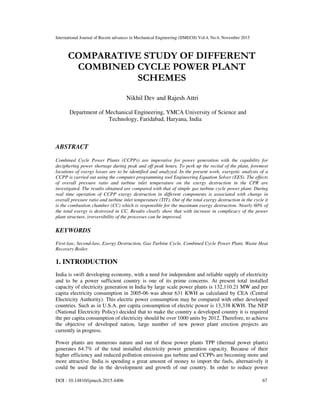
  • 3. International Journal of Recent advances in Mechanical Engineering (IJMECH) Vol.4, No.4, November 2015 69 2. CCPP SYSTEM DESCRIPTION In the Figure 1 schematic diagram of a GT based CCPP with inlet air cooling and evaporative after cooling of the compressor discharge is represented. Ambient air is filtered, cooled and humidified in the air filter (AF), air humidifier (AH1) before it counter passes the inlet air to the low-pressure compressor (LPC) in the air cooler (AC), cooling the inlet air. Air at 3 is cooled to a temperature that is close to the wet bulb temperature at 1. Compressed air from the low pressure compressor at 4 is cooled to 5 in an indirect intercooler using ambient humidified air that is humidified in the air humidifier (AH2) and has a lower temperature than ambient temperature. This cooled air enters the high-pressure compressor (HPC) and is compressed from state 5 to state 6. The outlet air of HPC at 6 is heated in heat exchanger with the exhaust flue gas coming out from turbine. Ambient air at point 6 enters the regenerative type heat exchanger (HE), and it exchanges heat with power turbine (PT). Afterward exhaust at point 11 is heated at point 7 after gaining heat and it is supplied to CC where fuel i.e. CNG is burned, producing hot gases at point 8. The hot flue gases are expanded at point 9 in the high-pressure turbine (HPT) and achieve lower pressure and temperature before re-combusted in the re-heater, after which the reheat flue gases are expands through a PT to drive air compressor and turbo-generator. Part of the heat of hot exhaust gas is used in the HE, and part of this heat is utilized in the WHRB to generate steam, and hence to produce the process heat. Fig. 1. Schematic line diagram of CCPP for the analysis
  • 4. International Journal of Recent advances in Mechanical Engineering (IJMECH) Vol.4, No.4, November 2015 70 3. MATHEMATICAL MODEL Exergy analysis is the combination of the first and second laws of thermodynamics to evaluate the efficiencies of processes and devices. If the system operates in a steady-state, steady flow condition and all the nonreacting gases are arbitrarily assigned as zero thermo-mechanical enthalpy, entropy, and exergy at the condition of ambient pressure and temperature regardless of their chemical composition, then the entropy of mixing different gaseous components can be neglected, and the general exergy-balance equation is given by: . . . . . 1 ( ) n W Q D i in out E E i me me E = = + − −∑ ∑ ∑ (1) For single stream flow, . . . . . ( )W Q in out DE E me me me= + − − (2) The mathematical equations for different components of the CCPP are tabulated in Table 1. Table 1. The exergy destruction rate equations for plant components Components Exergy Destruction Rate Air Compressor ,D AC in out ACe e e W= − + & Combustion Chamber ,D CC in f oute e e e= + − Gas Turbine , ( )D GT in out GTe e e W= − − & Heat Exchanger , m ( ) m ( )D HE air ai ao gas gi goe e e e e= − + − WHRB , m ( ) m ( )D WHRB gas gin gout w wout wine e e e e= − − − Air Filter , ( )D AF a ai aoe m e e= − Air Humidifier ,D AH ai ai w w ao aoe m e m e m e= + − Steam Turbine , ( )D ST s win wout STe m e e W= − − Feed Water Heater First , 1 1 14 1 20 21( )D FWH s s s se m e m m e m e= + − − Feed Water Heater Second , 2 2 15 1 2 18 1 19( ) ( )D FWH s s s s s se m e m m m e m m e= + − − − − Condenser , 1( )( ) ( )D COND s s win wout cw cwin cwoute m m e e m e e= − − + − Pump , ( )D P P s win woute W m e e= + −
  • 5. International Journal of Recent advances in Mechanical Engineering (IJMECH) Vol.4, No.4, November 2015 71 4. RESULTS AND DISCUSSION In this work, the dependencies of first-law efficiency second-law efficiency and power-to-heat ratio (PHR) on the operating parameters: pressure ratio (rp) and turbine inlet temperature (TIT) is examined with energy and exergy balance across each component of the CCPP represented in Figure 1. Table 2. Effect of CPR on efficiency and heat rate of the proposed CCPP and simple GT cycle Pressure Ratio Ist law efficiency of gas turbine (%) IInd law efficiency of gas turbine (%) Ist law efficiency of CCPP (%) IInd law efficiency of CCPP (%) Power to heat ratio 12 51.3 50.8 54.5 51 14.2 20 52.1 51.1 56.2 51.8 12.8 28 52.3 51.4 57 52 11.2 36 52.4 51.5 57.4 52.1 10.1 44 52.1 51 56.8 52 9.6 52 52 50.5 56.3 51.9 8.9 Table 2 shows the variation of PHR, first law efficiency, and second-law efficiency for the proposed CCPP and simple gas turbine cycle with variation in compressor CPR from 12 to 52 at TIT=1600 K and RH=60%. As the CPR rp augment the compressor work is increased due to higher aerodynamic resistance forces. It results in raising the temperature at the compressor outlet due to absorption of higher work by the air. Air compressor and gas turbine are interconnected and interdependencies is in such a manner that both energy absorbed by air compressor and work generated by gas turbine are increased. Net result is dependent upon the increase in TIT also, if possible. Higher flow of the air is adjusted with the inlet guide vanes with increase in compression ratio. All the components of the cycle are interdependent. Therefore, as rp increases the air temperature at the creek of HE decreases, that reduces the facility of HE due to lesser amount of heat transfer. Hence, the flue gas temperature at HE outlet is augmented. As rp increases the power-to-heat ratio decreases, since at much higher CPR the process heat increases significantly. As the CPR increases, it is observed that air temperature at the inlet of the combustion chamber decreases due to decrease in capacity of the HE, domino effect in increasing the heat added. The ratio of net work output to the heat added represents the first-law efficiency of the cycle. Hence, as rp increases, the first-law and second law efficiencies of the CCPP is strong function at rp =36 with the values of 57.4% and 52.1% respectively (Table 2). Results obtained are in line with the available in literature. Additional increase in rp reduces the efficiencies significantly because, at much higher CPRs, air mass flow rate is to be increased to fulfill the net requirement of work. Increase in air flow rate at compressor inlet increases fuel addition in combustion chamber.
  • 6. International Journal of Recent advances in Mechanical Engineering (IJMECH) Vol.4, No.4, November 2015 72 Table 3. Effect of TIT on efficiency and heat rate of the proposed CCPP and simple GT cycle TIT (K) Ist law efficiency of gas turbine (%) IInd law efficiency of gas turbine (%) Ist law efficiency of CCPP (%) IInd law efficiency of CCPP (%) Power to heat ratio 1300 44.2 44 47 44.1 23.1 1400 47.1 46.9 50.8 47 16.3 1500 49.2 49 53.9 49.1 12.2 1600 51.4 51.2 57 51.3 11.1 1700 53.2 53 59.7 53.1 9.7 1800 54.3 54.1 62 54.2 8.5 1900 56.2 56.1 64.8 56.2 8 Table 3 represents the deviation of the first-law, second-law efficiency, and PHR with the alteration in turbine inlet temperature at rp =36 and RH=60% for the proposed CCPP and simple gas turbine cycle. TIT is one of the most important design parameter. Its limiting value is dependent upon the thermal stress bearing capacity of gas turbine blade material. First stage turbine blades are more affected with the flue gas temperature than higher stage. Generally compressor of the gas turbine cycle is with seventeen stages of compression aerodynamic and gas turbine is with three stages of expansion. For a designed CPR and ambient relative humidity, the first-law and second-law efficiencies are added up due to better utilization of waste heat and increase in efficiency of gas turbine cycle. The increase in designed value of TIT enhances the heat transfer rate by absorbing greater heat from turbine exhaust in the heat exchanger, and hence the temperature of air inlet to the combustion chamber would increase, which in turn would increase the mean temperature of heat addition that leads to reduction of the cycle heat addition. Therefore, cycle efficiency increases with an increase in TIT. But the power-to-heat ratio decreases noticeably for the reason that increase in generation of process heat is greater than the electric power output at higher TIT (Table 3). Table 4. Results of CPR on exergy destruction in different components of the cycle for TIT = 1600 K, φ = 60%, Patm = 1 bar, Tatm = 298 K pr ,D LPEe (kJ/kg ) ,D Ie (kJ/kg ) ,D HPCe (kJ/kg ) ,D HEe (kJ/kg) ,D CCe (kJ/kg ) ,D HPTe (kJ/kg ) ,D RHe (kJ/kg) ,D PTe (kJ/kg ) ,D WHRBe (kJ/kg ) 12 13.43 5.57 11.01 63.14 182.3 21.81 129.8 23.21 9.95 20 14.89 7.64 13.13 60.07 204.2 27.69 161.4 27.32 13.61 28 14.73 9.47 14.27 51.53 218 29.83 184.9 32.51 15.32 36 15.69 10.83 14.93 41.27 228 35.17 198.7 32.58 17.48 44 15.97 11.79 15.21 36.76 235.7 36.15 209.5 34.67 22.18 52 17.82 12.63 15.72 35.21 242.1 43.32 218.5 40.17 22.17 Table 4 gives an idea about the exergy destruction in each component of CCPP with the change in overall cycle pressure ratio (CPR) for TIT=1600 K and RH=60%. Results in the Table 4 represents exergy destruction in the combustion process and it is found that combustion process dominates the exergy destruction in CCPP, as expected; it represents over 60% of the total exergy destruction in the overall system. The exergy destruction in the regenerative HE is next in the
  • 7. International Journal of Recent advances in Mechanical Engineering (IJMECH) Vol.4, No.4, November 2015 73 line. As CPR increases, the exergy destruction in the CC and re-heater increases significantly. This is because the increase in CPR implies higher combustion pressure, which leads to larger destruction. As CPR increases the temperature at the inlet of the intercooler increases. Thus, the temperature gradient for heat transfer in it increases with higher CPR. This explains more exergy destruction in the intercooler for higher CPR. On the other hand, the exergy destruction in the regenerative HE decreases as the CPR increases. This is because the higher CPR consequences in the lower power turbine egress temperature as well as higher temperature at the inlet of the WHRB. As a result, the exergy destruction in the WHRB increases with higher CPR. As CPR increases, the exergy destruction in WH decreases because the gas temperature at the exit of the WHRB decreases for a given PP (pinch point) temperature. At a given TIT, as the CPR increases the exergy destruction in the compressor and turbine increases. The exergy destruction in AH and AC are constant because at all CPR it has been used for the same working condition. The exergy destruction in the evaporative after cooler increases as CPR increases. Table 5. Effect of variation of TIT on exergy destruction in different components of the cycle for pr = 36, φ = 60%, Patm = 1 bar, Tatm = 298 K TIT (K) ,D LPEe (kJ/kg ) ,D Ie (kJ/k g) ,D HPCe (kJ/k g) ,D HEe (kJ/k g) ,D CCe (kJ/k g) ,D HPTe (kJ/kg ) ,D RHe (kJ/k g) ,D PTe (kJ/k g) ,D WHRBe (kJ/k g) 130 0 16.1 10.73 14.93 26.41 208 35.32 189.2 29.86 6.13 140 0 16.1 10.73 14.93 37.23 215.3 35.67 192.6 29.91 10.18 150 0 16.1 10.73 14.93 39.71 221.9 35.42 195.7 31.83 13.12 160 0 16.1 10.73 14.93 43.62 228 35.33 198.7 31.94 15.67 170 0 16.1 10.73 14.93 53.74 233.7 35.36 201.5 33.41 20.96 180 0 16.1 10.73 14.93 59.13 239.1 35.72 204.3 34.24 25.27 190 0 16.1 10.73 14.93 64.65 244.3 35.83 207.2 31.78 29.96 Results in Table 5 shows the disparity of exergy obliteration in every constituent of CCPP with the alteration in TIT at rp =36 and RH=60%. TIT is very much dependent upon the turbine blade material. For the higher cycle efficiency it is desired that TIT should be as high as possible. For higher TIT exergy destruction in the regenerative HE increases because the heat-transfer temperature gradient in it is also increased. It is discussed earlier that higher is the temperature difference amongst fluids more exergy is wasted. Constant heat transfer across higher temperature leads to higher exergy destruction in comparison to lower temperature gradient. It is due to higher degradation in energy quality. The exergy destruction in the CC and RH also increases because the logarithmic mean combustion temperature for the whole cycle increases. The exergy destruction in the WHRB increases because the temperature variation between the two heat exchanging fluids (flue gas and steam) increases, and for the designed CPR, more steam is generated by the WHRB with the higher TIT, which produces larger process heat. With increase in TIT the exergy destruction in WH decreases as the gas temperature at the exit of the WHRB decreases for a given pinch point temperature. The exergy destructions in AH, AC, EC,
  • 8. International Journal of Recent advances in Mechanical Engineering (IJMECH) Vol.4, No.4, November 2015 74 intercooler, AC, and power turbines are also shown in Table 5 and are constant. Again, CC and reheater are found to be a major source of irreversibility. 5. CONCLUSION The proposed CCPP in the present work is more complex than the simple cycle gas turbine cycle. It will increase the cost of installation and operation. For the life time cycle cost analysis represents that major part of it is due to fuel cost. Therefore, increased efficiency of the proposed CCPP will compensate for the installation and operation cost. Exergy analysis gives better insight into causes of cycle inefficiencies. Therefore, it is recommended to carry out energy and exergy analysis of a CCPP for the better understanding of the system. Nomenclature E  Exergy rate (kJ/s) LHV Lower Heating Value R Gas constant (kJ/kg K) T Absolute temperature (K) TP Process heat temperature (°C) W Work (kJ/kg (dry air)) cp Specific heat at constant pressure (kJ/kg K) cv Specific heat at constant volume (kJ/kg K) e Specific exergy (kJ/kg (dry air)) eP Specific exergy associated with process heat (kJ/kg) gr Gibbs function of fuel (kJ/kg) h Enthalpy (kJ/kg (dry air)) hf Enthalpy of saturated water at process steam pressure hg Enthalpy of saturated vapor at process steam pressure m Mass (kg) n Number of moles p Pressure (bar) Qp Process heat (kJ/kg (dry air)) rp Compression ratio s Entropy (kJ/kg K) t Temperature (°C) v Specific volume (m3 /kg) Greek Symbols ω Humidity ratio (kg of water vapor per kg of dry air) φ Relative humidity (%) ε Effectiveness (%) η Efficiency (%) γ Specific heat ratio Subscripts AC Air compressor CC Combustion chamber D Destruction GT Gas Turbine P Product
  • 9. International Journal of Recent advances in Mechanical Engineering (IJMECH) Vol.4, No.4, November 2015 75 Q Heat R Regenerator SG Steam Generator W Work a Ambient air av Average f Fuel g Gas i Inlet l Liquid o Outlet sat Saturated v Water vapor w Water 1,2,3,… State points in the cycle REFERENCES [1] Ahmadi P., Dincer I., (2011). Thermodynamic and exergoenvironmental analyses, and multi- objective optimization of a gas turbine power plant. Applied Thermal Engineering. 31, 2529-2540. [2] Butcher, C. J., Reddy, B. V. (2007). Second law analysis of a waste heat recovery based power generation system. International Journal of Heat and Mass Transfer. 50, 2355-2363. [3] Caton, J. A. (2000). A review of investigations using second law of thermodynamics to study internal combustion engines. SAE 2000-01-1081. [4] Dev, N., Attri, R., Goyal G. K., Kumar, N. (2013a). Exergetic Analysis of Combined Cycle Power Plant with Single Steam Extraction. ASME Gas Turbine India Conference, Bangalore. [5] Dev, N., Attri, R., Goyal G. K., Kumar, N. (2013b) Graph Theoretic Analysis of Advance Combined Cycle Power Plants Alternatives with Latest Gas Turbines. ASME Gas Turbine India Conference, Bangalore. [6] Dev, N., Attri, R., Sharma, V., Kumar, K. (2013c). Economic analysis of a cogeneration cycle power plant. International Journal of Management and Behavioural Sciences. 4, 184-189. [7] Dev, N., Attri, R. (2013). System modelling and analysis of a Gas turbine power plant using graph theoretic approach. International Journal of Energy, Environment and Economics. 21(1), 21-33. [8] Dev, N., Samsher, Kachhwaha, S. S., Attri, R. (2012). GTA based frame work for evaluating the role of design parameters in Cogeneration Cycle Power plant efficiency. Ain Shames Engineering Journal. 4(2), 273-284. [9] Dev N, Samsher, Kachhwaha SS and Attri R (2014a). Development of Reliability Index for Combined Cycle Power Plant using graph theoretic approach. Ain Shams Engineering Journal. 5, 193–203. [10] Dev N, Samsher, Kachhwaha SS and Attri R, (2014b). Development of Reliability Index for Cogeneration Cycle Power Plant Using Graph Theoretic approach. International Journal of Systems Assurance Engineering and Management. DOI 10.1007/s13198-014-0235-4. [11] Dev N, Samsher, Kachhwaha SS and Attri R. (2015). GTA Modelling of combined cycle power plant efficiency analysis. Ain Shams Engineering Journal. vol 6 (1), 217-237. [12] Khaliq, A., Kaushik, S. C. (2004). Thermodynamic performance evaluation of combustion gas turbine cogeneration system with reheat. Applied Thermal Engineering. 24, 1785-1795. [13] Kotowicz, J., Bartela, L. (2010). The influence of economic parameters on the optimal values of the design variables of a combined cycle plant. Energy. 35, 911-919. [14] Poma, C., Verda, V., Consonni, S. (2010). Design and performance evaluation of a waste-to-energy plant integrated with a combined cycle. Energy. 35, 786-793. [15] Regulagadda, P., Dincer, I., Naterer, G. F. (2010). Exergy analysis of a thermal power plant with measured boiler and turbine losses. Applied Thermal Engineering. 30, 970-976. [16] Woudstra, N., Woudstra, T., Pirone, A., Van der Stelt, T. (2010). Thermodynamic evaluation of combined cycle plants. Energy Conversation Management. 51, 1099-1110.