Welcome to International Journal of Engineering Research and Development (IJERD)

journal publishing, how to publish research paper, Call For research paper, international journal, publishing a paper, IJERD, journal of science and technology, how to get a research paper published, publishing a paper, publishing of journal, publishing of research paper, reserach and review articles, IJERD Journal, How to publish your research paper, publish research paper, open access engineering journal, Engineering journal, Mathemetics journal, Physics journal, Chemistry journal, Computer Engineering, Computer Science journal, how to submit your paper, peer reviw journal, indexed journal, reserach and review articles, engineering journal, www.ijerd.com, research journals, yahoo journals, bing journals, International Journal of Engineering Research and Development, google journals, hard copy of journal

Recomendados
Recomendados
Mais conteúdo relacionado
Mais procurados
Mais procurados (19)
Destaque
Destaque (7)
Semelhante a Welcome to International Journal of Engineering Research and Development (IJERD)
Semelhante a Welcome to International Journal of Engineering Research and Development (IJERD) (20)
Mais de IJERD Editor
Mais de IJERD Editor (20)
Welcome to International Journal of Engineering Research and Development (IJERD)
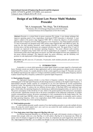
- 1. International Journal of Engineering Research and Development e-ISSN: 2278-067X, p-ISSN: 2278-800X, www.ijerd.com Volume 6, Issue 3 (March 2013), PP. 15-22 Design of an Efficient Low Power Multi Modulus Prescaler 1 Mr.A.Arunprasath, 2Mr.J.Raja, 3Dr.S.M.Ramesh 1,2 PG Scholar, M.E (VLSI Design) Department of ECE B.I.T,Sathy 3 Assistant Professor (Sr.G) Department of ECE B.I.T,Sathy Abstract:-Prescaler is a critical block in power conscious PLL design. A new design technique that improves operating speed of true single-phase clock-based (TSPC) prescalers is presented. A reset signal is added to the positive edge triggered TSPC DFF to obtain the objective of multi modulus prescaler that is frequency division (High frequency to low frequency). Two Dual-modulus prescalers 2/3 and 3/4 prescalers are designed using TSPC positive edge triggered DFF and CMOS nor gates. By using the two dual modulus prescalers, multi modulus prescaler is designed to provide multiple division ratios a`nd their performances are compared with previous work. The speed of the 2/3 and 3/4 prescaler are improved at the maximum operating frequency. The power efficient multi modulus prescaler is designed using Tanner EDA tool and its performance are compared. A Simulation and measurement results shows high-speed, low-power, low PDP and multiple division ratio capabilities of the power efficient technique. The improved speed, the power efficiency, and the flexibility will promote its wide deployment in Multi gigahertz range applications. Keywords:-tspc dff, cmos nor, 2/3 prescaler, 3/4 prescaler, multi modulus prescaler, pll, pseudo nmos nor, nmos nor I. INTRODUCTION A prescaler is a circuit which generates an output signal related to an input signal by a fractional scale factor. Prescaler circuits are useful in many applications such as clock generation in digital circuits and phase- locked loop (PLL) circuits. It is usually desired to divide a clock signal by an integer N. Prescalers are used in the feedback loop between the output of a Voltage-controlled oscillator (VCO) and the phase frequency detector in phase locked loop (PLL) frequency synthesizers to generate higher frequencies. 1.1 Dual modulus Prescaler The high-speed frequency divider is a key block in frequency synthesis. The prescaler is the most challenging part in the high-speed frequency-divider design because it operates at the highest input frequency. A dual-modulus prescaler usually consists of a divide-by-2/3 (or 4/5) unit followed by several asynchronous divide-by-2 units. The operation of the divide-by-2/3 unit at the highest input frequency makes it the bottleneck of the prescaler design. To achieve the two different division ratios, D flip-flops (DFFs) and additional logic gates, which reduce the operating frequency by introducing an additional propagation delay, are used in the unit. The power consumption of this divide-by-2/3 unit, which is the greatest portion of the total power consumption in the prescaler, significantly increases due to the power consumption of the additional components. In modern wireless communication systems, the power consumption is a key consideration for the longer battery life. The MOS current mode logic (MCML) circuit, which is of high power consumption, is commonly used to achieve the high operating frequency, while a true single-phase clock (TSPC) dynamic circuit, which only consumes power during switching, has a lower operating frequency. 1.2 Multi modulus prescaler A multi modulus prescaler usually consists of two dual modulus prescalers to provide multiple division ratios. By using the control signals (mc1, mc2, mc3) we can control the multi modulus prescaler to perform various frequency division operations. 1.3 True single phase clock Edge triggered d flip-flop with reset An efficient functional alternative to a D flip-flop can be made with dynamic circuits as long as it is clocked often enough; while not a true flip-flop, it is still called a flip-flop for its functional role. While the master–slave D element is triggered on the edge of a clock, its components are each triggered by clock levels. The "edge-triggered D flip-flop", as it is called even though it is not a true flip-flop, does not have the master– 15
- 2. Design of An Efficient Low Power Multi Modulus Prescaler slave properties. Edge-triggered D flip-flops are often implemented in integrated high-speed operations using dynamic logic. This means that the digital output is stored on parasitic device capacitance while the device is not transitioning. This design of dynamic flip flops also enables simple resetting since the reset operation can be performed by simply discharging one or more internal nodes. A common dynamic flip-flop variety is the true single-phase clock (TSPC) type which performs the flip-flop operation with little power and at high speeds. However, dynamic flip-flops will typically not work at static or low clock speeds: given enough time, leakage paths may discharge the parasitic capacitance enough to cause the flip-flop to enter invalid states. TSPC dynamic CMOS circuit is operated with one clock signal only to avoid clock skew problems. One reset signal is added with the TSPC circuit. Fig.1. below shows the TSPC flip-flop with reset. This TSPC circuit is used in the 2/3 and 3/4 prescaler. Fig.2. below shows the symbol of TSPC positive edge triggered d flip-flop. This symbol is used in 2/3 prescaler and 3/4 prescaler designs. Fig.1: TSPC Edge triggered d flip-flop Fig.2: TSPC Edge triggered d flip-flop – symbol 1.4 CMOS NOR GATE Nor gate is designed using CMOS transistors to achieve low power consumption. Various design techniques such as NMOS nor, Pseudo NMOS nor has been considered but the power consumption is high even though they have less no transistors, two and three transistors respectively. Fig.2. below shows the cmos nor gate. Fig.3. below shows the nmos nor gate and Fig.4. below shows the pseudo nmos nor gate. Fig.3: CMOS nor gate 16
- 3. Design of An Efficient Low Power Multi Modulus Prescaler Fig.4: NMOS nor gate Fig.5: Pseudo nmos nor gate II. DUAL MODULUS PRESCALERS 2.1 2/3 prescaler The 2/3 prescaler unit uses two TSPC edge triggered D flip-flop and two CMOS NOR gates as showed in the fig.6. Instead of TSPC D flip-flops, I have proposed a TSPC positive edge triggered D flip-flop. It includes reset signal as well. The output of the first D flip-flop is given to NOR gate as one of the input, and the other input is left for control signal mc. The output of the NOR gate is given to second NOR gate as one input and the other input is connected the input (D) of the first flip-flop. The output of the second NOR is given to second D flip-flop. Clock input (fin) is given to two D flip-flops. We can get the desired output (fout) from the output of the second D flip-flop. Two division operations are performed here, by changing the value of control signal (mc) as „1‟ or „0‟. When mc=‟1‟, the 2/3 prescaler is operated in divide by 2 mode. When mc=‟0‟, the 2/3 prescaler is operated in divide by 3 mode. Fig.8. below shows the symbol of 2/3 prescaler. This symbol is used in the multi modulus prescaler design. Fig.6: 2/3 Prescaler 17
- 4. Design of An Efficient Low Power Multi Modulus Prescaler Fig.7: 2/3 Prescaler – schematic diagram Fig.8: 2/3 prescaler – symbol 2.2 3/4 Prescaler The 3/4 prescaler unit uses TSPC positive edge triggered D flip-flop and two CMOS NOR gates as showed in the fig.8. Instead of TSPC D flip-flops, I have proposed a TSPC positive edge triggered D flip-flop. It includes reset signal as well. The output of the first D flip-flop is given to first NOR gate as one of the input, and the other input is left for control signal mc. The output of the first NOR gate is given to the second NOR gate as one input and the other input is given by inverted output (Qbar) of first D flip-flop. The output of the second NOR gate is given to second D flip-flop. Clock input (fin) is given to two D flip-flops. We can get the desired output (fout) from the output of second D flip-flop. Two division operations can perform here, by changing the value of control signal (mc) as „1‟ or „0‟. When mc=‟1‟, the 3/4 prescaler is operated in divide by 3 mode. When mc=‟0‟, the 3/4 prescaler is operated in divide by 4 mode. Fig.11. below shows the symbol of 2/3 prescaler. This symbol is used in the multi modulus prescaler design. Fig.9: 3/4 Prescaler Fig.10: 3/4 prescaler – schematic diagram 18
- 5. Design of An Efficient Low Power Multi Modulus Prescaler Fig.11: 3/4 prescaler – symbol III. MULTI MODULUS PRESCALER Multi modulus prescaler is designed using two dual modulus 2/3, 3/4 prescaler and CMOS NOR gates. Clock input (Fin) is given to 3/4 prescaler, the output of the 3/4 prescaler is given to 2/3 prescaler. The desired output (fout) is get from the 2/3 prescaler. Various control signals mc1, mc2, mc3 are used here to control the multi modulus prescaler to work in the desired divide mode. The block diagram of the multi modulus prescaler shown in fig.12. Fig.12: Multi Modulus Prescaler Fig.13: Multi Modulus Prescaler - schematic diagram Fig.14: Multi Modulus Prescaler - symbol 19
- 6. Design of An Efficient Low Power Multi Modulus Prescaler 3.1 Simulation results The Tanner EDA simulator is used to obtain the simulated output for Multi Modulus Prescaler. The simulated waveforms are obtained by assigning the inputs at various levels of extraction and the corresponding outputs are obtained from the assigned inputs. The outputs obtained are complementary with respect to the corresponding complementary inputs. We analyze and compare the proposed prescalers. The simulated waveforms of the proposed work are shown here Fig.15: Multi Modulus Prescaler - Divide by 8 mode when mc1=0,mc2=1,mc3=0. Fig.16: Multi Modulus Prescaler - Divide by 7 mode when mc1=0,mc2=1,mc3=1. Fig.17: Multi Modulus Prescaler - Divide by 9 mode when mc1=1,mc2=1,mc3=0. Fig.18: Multi Modulus Prescaler - Divide by 13 mode when mc1=1,mc2=0,mc3=1. 20
- 7. Design of An Efficient Low Power Multi Modulus Prescaler Table 1. Performance analysis of Multi Modulus Prescalers Multi Modulus Multi Modulus Prescaler - Prescaler - Proposed Conventional Voltage(v) Po Del Po No. Po Del Powe No.of.Tra w ay( wer of.T wer ay( r nsistors er ns) del ran (m ns) delay ( ay sist w) prod m pro ors uct(p w) duc J) t(p J) 1.5 0. 41. 5.2 0.07 15.9 1.131 12 215 34 1 43 72 7 140 2 0. 26. 6.8 0.15 15.7 2.497 25 755 76 9 05 7 21
- 8. Design of An Efficient Low Power Multi Modulus Prescaler IV. CONCLUSION Multi-modulus prescaler is a critical block in power conscious PLL design. A new design technique for high-speed low-power prescalers is presented. By modifying the, two Dff‟s in to TSPC positive edge triggered D flip-flops, including NOR gates in between two D flip-flops to provide multiple division ratios. This technique is applied to the 2/3 and 3/4 prescalers. With the help of those dual modulus prescalers, multi modulus prescaler has been designed. Comparing with the conventional designs, proposed multi modulus prescaler provides low power consumption and high speed as well. Power, Delay and Power Delay Product (PDP) are reduced. The primary objective of the prescaler is a frequency reduction that is also achieved. The improved speed, the power efficiency, and the flexibility will promote its wide deployment in multi gigahertz range applications. V. FUTURE ENHANCEMENT Further work can be carried out by still optimizing the architecture for power and delay by reducing the number of nodes by implementing Transmission Gates. REFERFNCES [1] Wu-Hsin chen and Byunghoo Jung, (2011) “High–Speed Low–Power True Single–Phase Clock Dual- Modulus Prescaler” IEEE transactions on circuits and systems—ii: express briefs, Vol. 58, No. 3, pp.144 -148. [2] Cao C, (2005), “A power efficient 26-GHz 32:1 static frequency divider in 130-nm bulk cmos,” IEEE Microw. Wireless Compon. Lett., Vol. 15, No. 11, pp. 721–723. [3] De Miranda F.P.H, Navarro Jr S.J, and Van Noije W.A.M, ( 2004), “A 4 GHz dual modulus divider-by 32/33 prescaler in 0.35 um CMOS technology,” in Proc. IEEE 17th Symp. on Circuits and Syst. Design, Vol. 17, pp. 94–99. [4] Huang Q and RogenmoserR,( 1996), “Speed optimization of edge-triggered CMOS circuits for gigahertz single-phase clocks,” IEEE J. Solid-State Circuits, Vol. 31, No. 3, pp. 456–465. [5] Ji-ren J, Karlsson I, and Svensson C, (1989), “A true single-phase-clock dynamic CMOS circuit technique,” IEEE J. Solid-State Circuits, Vol. 24, pp. 62–70. [6] Krishna M, Do M.A, Yeo K.S, C. C. Boon, andW.M. Lim, (2010), “Design and analysis of ultra low power true single phase clock CMOS 2/3 prescaler,” IEEE Trans. Circuits Syst. I, Reg. Papers, Vol. 57, No. 1, pp. 72–82. [7] Pellerano S, Levantino S, Samori C, and Lacaita A, (2004), “A 13.5-Mw 5- GHz frequency synthesizer with dynamic-logic frequency divider,” IEEE J. Solid-State Circuits, Vol. 39, No. 2, pp. 378–383. [8] Razavi B, Lee K, and Yan R.H, (1994), “A 13.4-GHz CMOS frequency divider,” in Proc. 41st IEEE Int. Solid-State Circuits Conf. Dig. Tech. Papers., pp. 176–177. [9] Vaucher C.S, Ferencic I, Locher M, Sedvallson S, Voegeli U, and Wang Z, (1994), “A family of low-power truly programmable dividers in standard 0.35 um CMOS technology,” IEEE J. Solid-state Circuits, Vol. 35, No. 7, pp. 1039–1045. [10] Wohlmuth H.D, and Kehrer D,( 2005),“A 24 GHz dual-modulus prescaler in 90 nm CMOS,” in IEEE Int. Symp. on Circuits and Syst., , Vol. 4, pp. 3227–3230. [11] Yu X.P, Do M.A, Lim W.M, Yeo K.S, and Ma J.G, (2006), “Design and optimization of the extended true single-phase clock-based prescaler,” IEEETrans. Microw. Theory Tech., Vol. 54, No. 11, pp. 3828– 3835. 22