Facilitando projetos de controle de motor com soluções ST
•
0 gostou•193 visualizações

Facilitando projetos de controle de motor com soluções ST Essa apresentação faz parte do Evento Online Mouser. Foi tratado durante o Webinar: Tipos de motores mais usuais hoje no mercado Portfólio ST para controle de motor Ferramentas de Software que a ST disponibiliza para controle de motor Confira a apresentação no Embarcados: https://www.embarcados.com.br/evento-online-mouser-electronics-desenvolvendo-grandes-ideias/

Recomendados
Recomendados
Mais conteúdo relacionado
Mais de Embarcados
Mais de Embarcados (20)
Último
Último (20)
Facilitando projetos de controle de motor com soluções ST
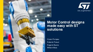
- 1. Motor Control designs made easy with ST solutions Cicero Pompeu Roberto Pieruci Rogerio Bueno William Maia
- 2. Agenda # Motor types and their fundamentals # ST Motor control portfolio # Microcontrollers ecosystems applied to Motor control 2
- 4. Electric motor: classification 4 • PMSM: 3-phase Permanent magnet synchronous motor • BLDC: Brushless DC motor • ACIM: 3-phase Induction motor and Single-phase induction motor • These are the most commom motors in the market.
- 5. DC Brushed motor 5 • Brushed DC motor are commonly used in industrial applications such as robots, valves and healthcare equipment. Current automotive solutions have plenty of DC motors. Toys are the universe of small DC brushed motors. • The brush DC motor is driven by directly applying a voltage to the motor leads. • Efficiency is good, about 70 to 85% due to its permanent magnet stator.
- 6. DC Brushed 6 • The rotor is composed of a group of coils • The stator magnetic field is generated by a permanent magnet • DC Motor current and torque are proportional • DC Motor voltage and speed are proportional
- 7. DC Brushed 7 • When only one direction of rotation is required, a single switch topology with PWM modulation can be used to vary the voltage applied to the motor, and thus to control its speed. • When positioning is required or when both directions of rotation are needed (e.g. car windows) a full H-bridge with PWM control is used. • ST offers a full set of integrated motor drivers and power MOSFETs and gate driver ICs to implement the required H-bridge.
- 8. Universal motor 8 • Universal motors can be used with AC or DC supplies and are commonly used in consumer appliances such as mixers, fans and vacuum cleaners. • Both stator and rotor are made by coils • Most universal motors are unidirectional. • Bidirectional motors using two coils on the stator can be driven by applying a voltage to only one of them for the respective direction. Alternatively, permuting the Stator connection related to the rotor. • Efficiency ranges from 30% for small motors to 75% for large motors.
- 9. Universal motor 9 • The advantages of universal motors are high starting torque, very compact design and high speed.
- 10. • A simple controller with an AC supply can be implemented using a low-end microcontroller and a single Triac or an AC switch. Universal motor 10 • Universal motor driver using DC mode topology can use chopping control thus improving efficiency and acoustic noises due to 3rd harmonic reduction.
- 11. Stepper motor 11 • Stepper motors are widely used in holding and positioning applications in the computer, security, industrial automation sectors. • The stepper motors are designed to keep a target angular position.This objective is obtained by splitting the rotation of the shaft in small fractions named steps. • There are different types of stepper motors: Unipolary, Bipolar (most common), 3-phase, 5- phase.
- 12. Stepper motor 12 • In bipolar stepper motors, current can flow in both directions;
- 13. Stepper motor 13 • Dual full-bridge converter is required to drive the two windings of a bipolar step motor. ST fully integrates monolithic motor driver ICs, embedding digital controllers, power devices and protection functions.
- 14. Stepper motor 14 • Full-step 1 (1,2,3,4) and full-step 2 (1b,2b,3b,4b): according to adopted stator magnetic field sequences; • Half-step: jointing Full-step 1 and 2. • Microstepping: Starting from half- step concept, it is possible to further increase the number of stable mechanical positions using the microstepping technique.
- 15. • Permanent Magnet synchronous motor and Brushless DC motors are replacing DC brush motors more and more in many applications due to advantages such as higher efficiency, quieter operation and better reliability. • PMSM and BLDC, both are three-phase, brushless and synchronous motors (rotor electrical speed equals to stator excitation frequency). BLDC - PMSM motors 15 • The rotor magnetic field is always present, and it is generated by a permanent magnet glued on the surface. • The highest torque among motors, efficiency 85% - 95%
- 16. BLDC - PMSM motors 16 • The scanning of the 6 driving combinations of the six steps is synchronized by the rotor position. • The rotor position can be monitored using Hall sensors or a BEMF sensing technique (sensorless). • 6-step driving imposes a current between two of the three phases leaving the third one floating. In this way the stator magnetic field can be positioned in 6 discrete directions. • BLDC: 6-step driving • Rotation induces trapezoidal Back Electro-Motive Force (BEMF) in motor phases; it gives best performance (torque steadiness) when driven by 6-step method.
- 17. BLDC - PMSM motors 17 • PMSM: Sinusoidal driving • Rotation induces sinusoidal Back Electro-Motive Force (BEMF) in motor phases; it gives best performance (torque steadiness) when driven by sinusoidal phase current • By applying three sinusoidal voltages with a delay of 120°in the motor phases it is possible to obtain three sinusoidal currents generating a rotating magnetic field. • allows a smoother operation compared to the 6-step method. • The Field Oriented Control (FOC) algorithm allows to obtain the maximum performance from a PMSM motor. • Optionally, the Space Vector Modulation can also be used. The SVM imposes a sinusoidal voltage between to adjacent phases applying a non sinusoidal voltage to the motor leads
- 18. BLDC - PMSM motors 18 Despite their different structures, all three-phase permanent magnet motors (BLDC, PMSM) are driven by a pulse-width-modulated (PWM) three-phase bridge (three half bridges). Special algorithms are applied to supply the motor with variable frequency and amplitude of voltages.
- 19. • AC induction motors, or Three-phase induction motors are brushless motors. • An AC induction motor is one of the simplest and most reliable types of electric AC motor, with the power ranging from a few watts to many kilowatts. • This motor is called Asynchronous motors (rotor electrical speed slips from stator excitation frequency). • The industry looks forward to find different ways to design and control such motors, power and speed. • The motor efficiency is quite good, from 75% to 85% ACIM or AC3P motor 19
- 20. • The stator is copper-coils and the rotor is typically an aluminum or copper squirrel cage. • By applying three sinusoidal voltages with a delay of 120° in the motor phases for 3-phase motor it is possible to obtain three sinusoidal currents generating a rotating magnetic field. ACIM or AC3P motor 20
- 21. 21 • It is very simple to implement highly efficient Variable-Frequency Drive (VFD) motor control, for low-power range motors. Scalar control. • For mid - high power range motors, the Field Oriented Control (FOC) algorithm allows to obtain the maximum performance from ACIM motor. • Optionally, the space vector modulation (SVM) can also be used. The SVM imposes a sinusoidal voltage between to adjacent phases applying a non sinusoidal voltage to the motor leads. 100% 50% 0% ACIM or AC3P motor
- 22. • The typical drive configuration is a three-phase bridge (3 half- bridges) modulated (PWM) to provide three sine wave voltages to the stator • The driving portion can be composed of power MOSFETs or IGBTs with high-voltage gate drivers, or power modules integrating three half-bridges and related gate driving stage. • FOC or Scalar control algorithms are implemented in the microcontroller that controls the inverter. ACIM or AC3P motor 22
- 23. • A single-phase AC induction motor is in fact a dual-stator coil, single-phase supplied by AC mains. • Different types of single-phase motors, with or without shift-phase capacitor, largely used by compressors, small pumps, garage door system, etc. • Induction motor is a brushless motor. Reliable (unless by the PSC), and simple. • The motor efficiency is OK, 60% to 70% Single phase ACIM motor 23
- 24. Single phase ACIM motor 24 • Speed control can be don by a triac arrangement, if unidirectional control, or dual triac if bidirectional control. • Phase-angle control provides low efficiency, however it is simple and chip. • Speed control can be done by a Inverter system; uses 3 half bridges, 90º /180º phased each other, eliminates the capacitor. • Speed control can also be done by AC chopper, but also not a very simple solution.
- 26. Motion Control Products and Architectures Partitioning Leading the convergence of analog and digital in motion control Control Logic Signal conditioning M Power Switches Power Management MOS / IGBT Drivers MCU Protections 1 1 STDRIVE Discrete Gate Drivers 2 STSPIN & PWD Motion Control SiP 3 2 STSPIN32 3
- 27. L647x Motor Control Portfolio: Quick Reference DC Motors 3ph BLDC Motors Stepper Motors Voltage 1-3 LiIon cells (up to 10V) 24V VBUS 12V VBUS Industrial battery pack (up to 7C) 48V .. 72V VBUS STSPIN240 STSPIN250 STSPIN230 STSPIN233 STSPIN220 L6206Q L6207Q L6226Q L6277Q L6235Q L6229Q STSPIN830 STSPIN32F0x* STSPIN840 L6208Q L6228Q STSPIN820 STDRIVE101* STSPIN32F025x* L648x* POWERstep01 up to 600V DC SLLIMM™ PWD13F60 PWD5F60 STSPIN32F060x* STDRIVE601 (*) to be paired with MOSFET/IGBTs
- 28. HID control FANs Medical equipment Power tools Drones 3D Printers Industrial automation ATM Toys and gaming Educational Robots E-Valves Stage Lighting Robotics Cameras Lens Control e-Door Lockers Pumps POS Textile machines When You Think of STSPIN, Think…. Assembly machines Label Printers Vacuum cleaners
- 29. STSPIN Family Positioning 45V 8V 85V 7V STSPIN220 10V 1.8V DC Stepper 3phase 52V 45V 7V Dual full-bridges VM = Voltage mode PCAD = Predictive Current control with Adaptive Decay DME = Digital Motion Engine generates motion profiles thru commands sent over SPI 3A, Rdson=0.28Ω 1.3A, Rdson=0.2Ω 256usteps step clk/dir inputs PWM I control 1.4A; 0.7Ω2.8A; 0.3Ω L6470 (VM) L6472 (PCAD) L6208 L6208Q L6480 (VM) L6482 (PCAD) Controllers & SiP POWERSTEP01 10A, Rdson=16mΩ Microsteppig motor drivers Dual full-bridge STSPIN240 STSPIN250 1.3A, Rdson=0.2Ω Direct PWM inputs Parallel Outputs for higher I Embedded Current control Dual full-bridge STSPIN230 STSPIN233 1.3A, Rdson=0.2Ω Direct inputs driving Embedded Current control Suitable for FOC Triple half-bridge Dual full-bridges Integrated microstepping controller Dual full-bridges Parallel operation, PWM control L6228 L6228Q Triple half-bridges L6205 L6206/Q L6207/Q L6225 L6226/Q L6227/Q 1.4A; 0.7Ω2.8A; 0.3Ω L6235/Q (PWM / Hall) . L6234 L6229/Q (PWM/Hall) . L6230/Q (FOC) 1.4A; 0.7Ω2.8A; 0.3Ω L6474 Low Voltage motor drivers Monolithic Versatile motor drivers High Power microstepping STBY consumption <150nAScalable, Safe & Wide Portfolio Silent, Smooth & High Performance Motion STSPIN820 256usteps 45V; 1.5A; 0.5Ω STSPIN840 45V; 1.5A; 0.5Ω STSPIN830 (FOC) 45V; 1.5A; 0.5Ω 12V LDO & 3.3V DC-DC STSPIN32F0/A/B 45V 6.7V STSPIN32F0H High Voltage SiP for 3-phase BLDC 21V 8V STM32 M0 + 3 phase Drivers, 600mA Sensored / sensorless FOC & 6step control Low Voltage SiP for 3-phase BLDC VOUT up to ● 250V (STSPIN32F0251/2) ● 600V (STSPIN32F0601/2)
- 30. STSPIN2 Series Tools & Ecosystem Product Board Firmware Ecosystem Documentation Availability STSPIN220 Stepper motor driver X-NUCLEO-IHM06A1 X-CUBE-SPN6 SPINFamily GUI + NUCLEO-F401 Step mode selection (AN4923) Eval board manual (UM2082) FW manual (UM2083) On stock STSPIN230 3-phase 1 shunt BLDC motor driver X-NUCLEO-IHM11M1 X-CUBE-SPN11 FOC library (STSW-STM32100) MC Workbench + NUCLEO-Fxxx (*) Eval board manual (UM2095) FW manual (UM2106) MC Workbench guidelines On stock STSPIN233 3-phase 3 shunts BLDC motor driver X-NUCLEO-IHM17M1 X-CUBE-SPN17 FOC library (*) (STSW-STM32100) MC Workbench + NUCLEO-Fxxx (*) Eval board manual FW manual MC Workbench guidelines On stock STSPIN240 Dual brushed DC motor driver X-NUCLEO-IHM12A1 X-CUBE-SPN12 SPINFamily GUI + NUCLEO-F401 Eval board manual (UM2112) FW manual (UM2110) On stock STSPIN250 Single brushed DC motor driver X-NUCLEO-IHM13A1 X-CUBE-SPN13 SPINFamily GUI + NUCLEO-F401 Eval board manual (UM2148) FW manual (UM2161) On stock
- 31. STSPIN8 Series Tools & Ecosystem (*) Compatible, but not directly supported. Dedicated manual will be provided in the documentation (**) Will be available in Q3 2020 Product Board Firmware Ecosystem Documentation Availability STSPIN820 Stepper motor driver X-NUCLEO-IHM14A1 X-CUBE-SPN14 SPINFamily GUI + NUCLEO-F401 (**) Eval board manual (UM2299) FW manual (UM2300) On stock EVALSP820-XS (Motion Control Shield for Arduino/RAMPS 3D Printers) Eval board manual On stock STSPIN840 Dual brushed DC motor driver X-NUCLEO-IHM15A1 X-CUBE-SPN15 SPINFamily GUI + NUCLEO-F401 (**) Eval board manual FW manual On stock STSPIN830 3-phase 3shunts BLDC motor driver X-NUCLEO-IHM16M1 X-CUBE-SPN16 FOC library (*) (STSW-STM32100) MC Workbench + NUCLEO-Fxxx (*) Eval board manual FW manual MC Workbench guidelines On stock
- 32. IPM approach BLDC VFD based on IPM +3.3VDC AC Mains M H High Voltage Aux. Supply - + ref. Linear Reg. SLLIMM™ 2nd Series IPM From 5 to 30A Position Sensors Shunt Resistor(s) TSV7/9x, TSX7x, TS3x, LMV3xx Op Amps and Comparators LDKxx, LDLxx, LFxx, L78x33 LDO and Voltage Regulators MCU STM32F0/F1/F3 STTHxL06 Ultrafast High Voltage Rectifier 3+3 PWM signals Current sensing SD / OD Optional feature Embedded NTC Speed sensing - + ref. High Voltage Converter VIPerx6, VIPerx7 HV DC Bus +15VDC BLDC Motor Smart Shut-Down Unique ST Feature HV Triple Drivers Embedded HV HS Triple Smart Driver Control Unit HV LS Triple Smart Driver TSO Driver Temperature
- 33. Discrete approach 3 phase variable frequency drive +3.3VDC AC Mains C High Voltage Aux. Supply - + ref. Linear Reg. TSV7/9x, TSX7x, TS3x, LMV3xx Op Amps and Comparators LDKxx, LDLxx, LFxx, L78x33 LDO and Voltage Regulators MCU STM32F0x STTHxL06 Ultrafast High Voltage Rectifier 3+3 PWM signals Current sensing High Voltage Converter VIPerx6, VIPerx7 HV DC Bus +15VDC Motor HB Drivers (with Comp/Opamp options) L639x, L638x Control Unit Shunt Resistor Shunt Resistor Shunt Resistor HV HB Smart Driver HV HB Smart Driver HV HB Smart Driver MDmesh™ DM2 MOSFET Series STD5N60DM2, STx6(7)N60DM2
- 34. Discrete approach – power modules + gate driver 1/2 Standard products in MP (solder and Press FIT pins) ACEPACK™ 1 ACEPACK™ 2 CIB + NTC Six-Pack + NTC Part Number Topology BVCES IC rating A1P25S12M3/-F Six-Pack 1200V 25A A1P35S12M3/-F 35A A1C15S12M3/-F Converter Inverter Brake 1200V 15A A1P50S65M2/-F Six-Pack 650V 50A Part Number Topology BVCES IC rating A2C25S12M3/-F Converter Inverter Brake 1200V 25A A2C35S12M3/-F 35A A2P75S12M3/-F Six-Pack 1200V 75A A2C50S65M2/-F Converter Inverter Brake 650V 50A
- 35. Discrete approach – power modules + gate driver 2/2 A future-proof portfolio for a wide range of applications Single Channel & low side TD35, PM88 Series High-Voltage Half- Bridge L638, L639 Series High-Voltage Half- Bridge L649 Series Galvanic Isolated STGAP Series High-Voltage 3-phase STDRIVE601 NEW BCD-OFFLINE
- 36. L6491D 4A Gate Drive Capability source / sink Comparator interlocking & adjustable DT SmartSD Protections: UVLO Vcc / Vboot SO-14 Package L6494L 2A source/ 2.5A sink Gate Drive Capability Single input and Shutdown pin Interlocking & adjustable DT protections: UVLO Vcc / Vboot SO-14 Package (P2P with IR21844S & FAN7393) Features • 600V Half-Bridge • Up to 4A gate driving current capability • On-chip OpAmp for current sensing • Embedded Comparator for enhanced protection thanks to fast internal loop • Integrated Bootstrap Diode • Adjustable Dead Time L6498 / L6498L 2A source/ 2.5A sink Gate Drive Capability Active-High LS & HS inputs interlocking, Protections: UVLO Vcc / Vboot L6498L: SO-8 Package (P2P with IR2181S) L6498: SO-14 Package (P2P with IR21814S) L649x: high current platform NEW Outstanding robustness, noise immunity and design flexibility UVLOUVLO Embedded features optimized for Field Oriented Control (F.O.C.) applications
- 37. 3-phase High Voltage BLDC gate driver STDRIVE601 – 600V Triple Gate driver Key features • Best In Class for propagation delay 85ns • 200mA/350mA sink / source driver current • Zero-drop Integrated bootstrap diode • Interlocking and deadtime function • SmartSD: fast over current protection Value & Benefits • Compact and simplified layout • Extreeme robustness • Optiomized low EMI KEY APPLICATIONS • 3-phase Motor driver • Home appliances • Industrial drives and Fans Now QUALIFIED! • New BCD6-OFFLINE technology and optimized design allow reaching outstanding ruggedness and immunity to below-ground spikes
- 38. STDRIVE101 3phase BLDC Gate Driver KEY APPLICATIONS • Home appliances • Power tools • Factory automation • Fans and pumps • Robotics • Operating Voltage: 5V to 75V • I = 600mA sink/source driving capability • 12V LDO embedded • Programmable Dead Time • Desaturation (MOS Short Circuit) protection; programmable • Fully protected (UVLO, OCP, thermal shutdown) • Very short propagation delay 70ns; 20ns phases matching • Compact design with 4x4mm QFN • Integrated bootstrap diodes • Standby mode for low consumption Key Features
- 39. STGAP2S 1700 V, 4A isolated gate drivers • Active High & Active Low input pins, for HW interlocking • STGAP2C: Separated Outputs option for easy gate driving tuning • STGAP2SC: Miller CLAMP pin option to avoid induced turn-on • Negative gate drive ability • SO8 Package • 3V3 / 5 V logic inputs (logic thresholds 1/3, 2/3 of VDD ) • Up to 26 V supply voltage • 4 A Sink/Source current capability • Short propagation delay: 80 ns • UVLO Function • Stand-by function • 100 V/ns CMTI • High voltage rail up to 1700 V • Temperature shut-down protection
- 40. STGAP2D 1700 V, 4A isolated gate drivers • Single input pin, in phase with output • Shut-Down SD pin, with integrated pull-down • BRAKE pin • Interlocking • Negative gate drive ability • SO16 Package • 3V3 / 5 V logic inputs (logic thresholds 1/3, 2/3 of VDD ) • Up to 26 V supply voltage • 4 A Sink/Source current capability • Short propagation delay: 80 ns • UVLO Function • Stand-by function • 100 V/ns CMTI • High voltage rail up to 1700 V • Temperature shut-down protection KEY APPLICATIONS • Motor control • Factory automation • Industrial drives and fans • DC-DC converters • Induction heating • Welding
- 42. Control Logic Signal conditioning M Power Switches Power Management MOS / IGBT Drivers MCU Protections STSPIN & PWD Motion Control SiP 3 3 1 STDRIVE Discrete Gate Drivers 2 STSPIN32 STSPIN and PWD products
- 43. STSPIN Systems-in-Package Our Excellences Microcontrollers Motor Drivers SiP evolution Driver + Power stage Driver + STM32 More Power Density…. and More Intelligence MOS
- 44. PWD Series Overview We sell in • Industrial/Home appliances • Factory automation • Fans, pumps and blowers • HID, ballasts • Cooking hoods and gas heaters • Power supply units Main Applications + 3-phase BLDC PWD5T60 • 6x MOS: IOUT = 3.5A & RDS(ON) = 1.38 Ω • Fast recovery Diode (trr=70ns) • Integrated bootstrap diodes • 1 Comparator for OCP embedded • Smart shutdown (smartSD) function PWD13F60 • 4x MOS: IOUT = 8A & RDS(ON) = 320 mΩ • Integrated bootstrap diodes • VCC: 6.5V – 19V • INx and OUTx in phase • UVLO and interlocking protections Brushed DCBrushed DC/1phase BLDC PWD5F60 • 4x MOS: IOUT = 3.5A & RDS(ON) = 1.38 Ω • Fast recovery Diode (trr=70ns) • Integrated bootstrap diodes • 2 uncommitted Comparators • Programmable Dead Time up to 600 V
- 45. Control Logic Signal conditioning M Power Switches Power Management MOS / IGBT Drivers MCU Protections 2 2 STSPIN32 STSPIN & PWD Motion Control SiP 3 1 STDRIVE Discrete Gate Drivers STSPIN32 Products Leading the convergence of analog and digital in motion control
- 46. STSPIN32 Technology, from LV to HV 45V STSPIN32F0/A/B KEY APPLICATIONS • Home Appliances • Air conditioning • Home and Industrial refrigerators • Industrial Pumps • High-end power tools • Industrial automation KEY APPLICATIONS: • Industrial automation • Robotics • Fans • Battery powered Home Appliances • Drones and aeromodelling • Power tools 250V & 600V STSPIN32F0H STSPIN32 evolution: from 45V to High Voltage advanced 3-phase BLDC Driver
- 47. We sell in• Compressors, pumps and fans • Power tools • Vacuum cleaners • Industrial automation and control • Home Appliances • Drones (gimbal and ESC control) Main Applications 3phase BLDC 9 – 250 V6.7 – 45 V 9 – 600 V STSPIN32F0/A/B • 0.6A FOC/6-step gate drivers • 12V / 3.3V V reg embedded • 1 and 3 shunt topologies STSPIN32F0251/2 • 0.3A / 1A FOC/6-step gate drivers • Smart ShutDown protection • Outstanding below-gnd robustness • 1 and 3 shunt topologies pin to pin + STSPIN32F0601/2 • 0.3A / 1A FOC/6-step gate drivers • Smart ShutDown protection • Outstanding below-gnd robustness • 1 and 3 shunt topologies Low Voltage High Voltage STSPIN32F0 Series Overview
- 48. STSPIN32F060x/25x • STM32 Cortex M0 + 3-phase Driver • Fully compatible with STM32 ecosystem • 6step & FOC sensorless / sensored algorithms • 0.35A & 1A I capability • All devices P2P among them Key Features KEY APPLICATIONS • 36V – 120V Power and garden tools • Air conditioning compressors & FANs • Home and Industrial refrigerators compressors • Industrial Pumps • High power tools • Industrial automation • Extremely compact & flexible solution • Exaustive ecosystem for fast design • High below-ground robustness • High immunity / Low EMI Noise Value & Benefit Advanced 250V/600V 3-phase BLDC Driver with embedded STM32 MCU
- 49. STSPIN32F0/A/B Evaluation Tools c) a) b) Full ecosystem of HW, FW & SW for easy and fast design a) STEVAL-SPIN3201 (FOC 3 shunts sensorless/sensored FWs; based on STSPIN32F0) b) STEVAL-SPIN3202 (FOC 1 shunt & 6 step sensorless/sensored FW; based on STSPIN32F0A) c) STEVAL-ESC002V1 (Compact ref design for ESC based on STSPIN32F0A & high-speed 6-step FW) d) STEVAL-SPIN3204 (1 shunt 6 step sensorless/sensored FW; based on STSPIN32F0B)
- 50. STSPIN32F0 HV Ecosystem Board Firmware Ecosystem Documentation Availability EVSPIN32F0601s1 (STSPIN32F0601) 1-shunts dev board with ST-LINKV2-1 SW-SPIN32F0601S1 FOC library (X-CUBE-MCSDK) SDK 5.4.1 Eval board manual FW manual On stock EVSPIN32F0601s3 (STSPIN32F0601) 3-shunts dev board with ST-LINKV2-1 SW-SPIN32F0601S3 FOC library (X-CUBE-MCSDK) SDK 5.4.1 Eval board manual FW manual On stock EVSPIN32F0602s1 (STSPIN32F0602) 1-shunts dev board with ST-LINKV2-1 SW-SPIN32F0602S1 FOC library (X-CUBE-MCSDK) SDK 5.4.1 Eval board manual FW manual On stock EVSPIN32F0251s1 (STSPIN32F0251) 1-shunts dev board with ST-LINKV2-1 SW-SPIN32F0251S1 FOC library (X-CUBE-MCSDK) SDK 5.4.1 Eval board manual FW manual On stock Download the FW example on PC and run your BLDC motor EVSPIN32F0601s1
- 51. Microcontrollers ecosystem for Motor controlTM32 Motor Control Solutions July 2020 Cicero Pompeu – PME William Maia - FAE
- 52. Electric Motor: Classification Electric motors AC Synchronous PMSM (FOC) BLDC (6-step) Asynchronous (ACIM) Variable reluctance Switched reluctance StepperDC (brushed) Universal • PMSM: 3-phase permanent magnet synchronous motor • ACIM: 3-phase induction motor Complex driving, Computation intensive, Requires 3-phase timer + sync’d ADC, Limited computation need, Basic ADC/PWM requirements STM32/STM8 solutions Software Development Kit (SDK) Software Examples Software Examples 52
- 53. STM32 Products for Motor Control
- 54. STM32 portfolio 17 product series / More than 50 product lines Note: Cortex-M0+ Radio Co-processor Dual Core Cortex-A7 & Cortex-M4 Ultra Low Power Mainstream Cortex-M0 Cortex-M0+ Cortex-M3 Cortex-M4 Cortex-M7 High Performance Wireless Cortex-M33 Cortex-M7 & Cortex-M4 Multi Core MPU Advanced Motor Control Timer(s) included 54
- 55. STM32 today – platform effect Select the best fitting product from a wide & compatible portfolio 55 Flash memory size (Kbytes) 8 2048 16 32 64 128 192 256 384 512 768 1024 1536 14 20 25 28 32 36 48 49 63 64 71 72 100 104 132 66 81 90 143 144 169 176 208 216 240 Pin count Typical range for advanced motor control
- 56. STM32F3: Shaped for Motor Control 56 High performance 72MHz ARM Cortex-M4 with FPU Equipped with advanced Motor Control timer(s) Rich advanced analog integration and optimized for the control loop From 32 KB to 512KB flash memory in a wide range of packages Fast 12-bit ADC 5Msps Interconnect BUS Matrix Control Loop Booster CCM-RAM 12-bit DAC HW safety SIL ready, Class B, Ultra Fast Comparator (25ns) 85°C 105°C Op-Amp with 7 gains Extended Temperature range
- 57. STM32F30x products 57 VDD=1.8V +/- 8% 32KB-512KB Flash / 4KB-20KB SRAM 10x 16-bit timer including MC timer 1x 32-bit timer 3x SPI, 2x I2C, 5x USART, CEC,USB(*) 12-bit DAC(**), 12-bit ADC(**),Comp(**) (*) Check P/N not always present (**)Analog with separate power supply 2.4V STM32F3*8 STM32F3*2 VDD = 2.0 to 3.6V 16KB-512KB Flash /8KB-64KB SRAM USB FS, CAN 1x MC timer Up to 2xADC 5Msps, 4x Comp, 2x Op- Amp, 1xDAC VDD = 2.0 to 3.6V 16KB-512KB Flash / 8KB-64KB SRAM 4k to 16KB CCM SRAM USB FS, CAN Up to 3x MC timer Up to 4xADC 5Msps, 7x Comp, 4x Op- Amp, 3xDAC STM32F3*3 STM32F3*1 VDD = 2.0 to 3.6V 16KB-64KB Flash / 10KB-16KB SRAM 1x MC timer Up to 1xADC 5Msps, 3x Comp, 1x Op- Amp, 1xDAC 256 K 128 K 48 pins LQFP WLCSP 49 64 pins LQFP 100 pins LQFP/BGA/W LCSP 64 K F303-32kB RAMF303-32kB RAM F303-40kB RAM F302-32kB RAM F302-24kB RAM F302-32kB RAM F302-24kB RAM F303-40kB RAM F303-32kB RAM F302-32kB RAM F302-24kB RAM F303-40kB RAM F358-40kB RAM F358-40kB RAM F358-40kB RAM 512 K 32 K F301-16kB RAM F301-16kB RAM F301-16kB RAM F303-64kB RAM F302-64kB RAM F398-64kB RAM F318-16kB RAM F303-64kB RAM F302-64kB RAM F398-64kB RAM 32 pins LQFP / UFQFPN F301-16kB RAM F318-16kB RAM F302-16kB RAM F302-16kB RAMF302-16kB RAM F302-16kB RAM F302-16kB RAMF302-16kB RAM F303-16kB RAMF303-16kB RAMF303-16kB RAM F303-16kB RAMF303-16kB RAMF303-16kB RAM F318-16kB RAM F328-16kB RAMF328-16kB RAM F328-16kB RAM F303-64kB RAM F302-64kB RAM F398-64kB RAM Flash size (bytes) 144 pins LQFP F301-16kB RAMF301-16kB RAM 57
- 59. Secure Live Upgrade Functional safety design packages Safety and security focus • Dual Bank Flash with ECC (error code correction) • Securable Memory Area • Hardware encryption AES-256 • SIL, Class-B • SRAM with Parity bit STM32G4 Series – Key Messages 59 Performance • Arm® Cortex®-M4 at 170 MHz • 213 DMIPS and 550 CoreMark® results • Better dynamic power consumption (163µA/MHz) • ART Accelerator™ (dynamic cache) • Mathematical accelerators • CCM-SRAM Routine Booster (static cache) Rich Integrated Analog and Digital • Op-Amps (Built-in gain), DACs, Comparators • 12-bit ADCs 4Msps with hardware oversampling • CAN-FD (flexible data rate – 8Mbps bit rate) • High resolution timer (184 ps) • USB type-C Power Delivery3.0 • 1% RC accuracy [-5°..90°C], 2% full T° range Complete portfolio • Complements existing STM32F3 Series portfolio • From -40°C up to 85 or 125°C devices • From 32- up to 128-pin • From 32KB to 512KB Flash
- 60. Rich, Advanced Analog Mixed-signal SoC for wide variety of applications Op-Amp (up to 6) Values GBW 13 MHz Slew rate 45 V/µs Offset 3mV over full T° range 1.5mV @ 25°C PGA Gain (accuracy) 2, 4, 8, 16, -1,-3,-7,-15 (1%) 32, 64, -31,-63 (2%) Comparator (up to 7) Values Power supply 1.62 .. 3.6V Propagation delay 16.7ns Offset -6 .. +2 mV Hysteresis 8 steps: 0, 9, 18, 27, 36, 45, 54, 63 mV DAC (up to 7) Values Sampling rate 15 Msps (internal) 1Msps (from buffered output) Settling time 16ns ADC (up to 5) Values Topology SAR 12-bit + HW oversampling → 16-bit Sampling rate Up to 4 Msps Input Single-ended and differential Offset and Gain compensation Auto calibration to reduce gain and offset 60
- 61. Rechargeable devices, drones, toys • Low-thickness, small form-factor • Low consumption in run mode ~ 160µA/MHz • Embedded analog • SAI (Sound Audio Interface) • USB type-C Power Delivery 3.0 Key Features for Targeted Applications Servers, Telecom, EV Charging station • Fast CPU 170 MHz • Mathematical accelerator (Filtering) • 12ch High Resolution timer (184ps) • 4Msps ADC-12bit + HW oversampling • Fast comparators (17ns) • Embedded analog • Dual bank flash for live upgrade • AES & security • FMAC for 3p3z compensation Home appliances, E-bikes, Air Conditioning • Fast CPU 170MHz • Mathematical accelerator (Cordic) • Advanced Motor Control timers • Fast comparators • 4Msps ADC-12bit + HW oversampling • Op-Amp with built-in gain (PGA) • DAC-12bit • 1% RC accuracy (UART communication w/o external Xtal) Industrial equipment • Fast CPU 170MHz • Mathematical accelerator (Cordic) • High temperature 125°C • CAN FD support • SPI, USART, I²C • Advanced timers • Real Time Clock with backup registers • Dual bank flash for live upgrade • AES & security MotorControl 61 Industrialdevices Measurements High-End Consumer DigitalPower
- 62. Ease Digital Power Conversion Wireless charger Welding Motor control Lighting Telecom power Servers and Data center Industrial UPS PV Inverters Power Factor correction Enhance your digital power solutions using the STM32G4’s full features High Resolution Timer (HRTIM) 62
- 63. STM32F30x STM32G4 Products Lines Analog STM32G4x1 Memory Pin Count 512KB 32KB 128-pin32-pin STM32G4x3 STM32F334 STM32G4x4 Digital PowerMemory Pin Count 512KB 32KB 128-pin32-pin Performance line 63 Access line Hi-Resolution line General Purpose Applications Specific
- 64. Extensive & Innovative Peripheral Set Unit parameters STM32G474 Hi-Resolution line STM32G473 Performance line STM32G431 Access line Core, frequency Arm Cortex-M4, 170 MHz Flash (max) 512 Kbytes (2x256KB dual bank) 128 Kbytes single bank RAM (up to) 96 Kbytes 22 Kbytes CCM –SRAM (code-SRAM) 32 Kbytes 10 Kbytes 12-bit ADC SAR 5x 12-bit 4 MSPS 2x 12-bit 4 MSPS Comparator 7 4 Op amp with 4 built-in gain values with 1% accuracy 6 3 12-bit DAC 7 4 Motor Control timer 3x (170 MHz) 2x (170 MHz) CAN-FD 3x 1x 12 channel Hi-resolution Timer 1x - - Power supply 1.72 to 3.6 V No compromise on what matters 64
- 65. Shaped for Control 65 PWM Timers * 170 MHz (5.9ns) * HRTIM (184ps) + - Set point Direct HW path (no latency) • Instantaneous control load • Protection PWM PLANT + - 7xDAC Analogfeedback Multiple fast Comparators Digitalfeedback 6x PGA High Bandwidth Low offset Programmable Gain Other Timers • Quad encoder • Halls sensors 7xComp - 5x 12-bit 4Msps ADC • SAR (no pipeline delay) • Low latency (250ns) • Low aperture time (20ns) for snapshot measurements • Simultaneous sampling on multiple ADCs • HW oversampling ARM Cortex-M4 core @ 170MHz • FPU • Enhanced dynamics • No scaling overhead • No saturation • DSP (fast MAC) • SIMD • Parallel processing • Low interrupt latency ST’s product architecture • ART accelerator • Wait state removal • CCM-SRAM accelerator • Real time execution • Math accelerator • Cordic (Trigo) • FMAC (Filtering) Easy to use the Analog and Digital resources thanks to high peripherals interconnect and flexible bus matrix
- 67. STM32G4 Hardware Solutions 67 Accelerate evaluation, prototyping and design Flexible prototyping • NUCLEO-G431RB • NUCLEO-G474RE • NUCLEO-G431KB* STM32 Nucleo 64-pin 32-pin* Key feature prototyping • B-G474E-DPOW1* • B-G431B-ESC1* Discovery kits Full feature STM32G4 evaluation • STM32G484E-EVAL • STM32G474E-EVAL • STM32G474E-EVAL1 Evaluation boards Full feature for Motor Control and Analog • P-NUCLEO-IHM03 Motor Control Pack Order yours now on Mouser website!
- 68. STM32CubeMX • Configure and generate Code • Conflicts solver Flexible Solutions • Partners IDE, like IAR and Keil • Free IDE based on Eclipse, like STM32CubeIDE* STM32CubeProgrammer • Flash and/or system memory • GUI or command line interface STM32G4 Software Tools 68 Complete support of Arm Cortex-M ecosystem STM32CubeMX IDEs Compile and Debug STM32 Programming Tool *: STM32G4 is usable with STM32CubeIDE, but examples delivered in STM32CubeG4 are not yet available. STM32CubeIDE users can however import those SW4STM32 projects
- 69. Dedicated Ecosystems 69 • Complete ecosystem (HW boards, SW Development Kit (SDK), docs and trainings) • X-CUBE-MCSDK (v5.4) • Motor Control FW library based on STM32Cube HAL and LL • Motor control workbench: Graphical configurator of the motor control library linked with STM32CubeMx • P-NUCLEO-IHM03: Motor Control Nucleo pack • NUCLEO-G431RB Nucleo-64 • X-NUCLEO-IHM16M1 motor driver expansion board • Low Voltage motor • State of the art algorithms (FOC, 6-step, sensorless…) • Motor Profiler: Plug and spin your motor within less than one minute Motor Control • Complete ecosystem (HW boards, FW examples, SW tools, docs and trainings) • Dedicated HRTIM Cook Book - AN4539: How to operate the Hi-Resolution timer in different topology • Digital Power training (PSU and PFC) – based on STM32 G4 series – done in collaboration with Biricha (from Q4 2019) Digital Power
- 70. 2002 2005 2008 2009 2011 2013 2014 2016 2018 ST9 ST7FMC 8/16-bit MCU for ACIM with dedicated library 8-bit MCU for MC scalar and 6-step control with MC HW & SW kit 32-bit CM3 MCU & sensor-less FOC library v1.0 8-bit MCU & MC kit for scalar and 6-step control FOC SDK v3.0 - dual motor FOC control & MCWB FOC SDK v3.4 - new analog & HW accelerator FOC SDK v4.0 - high frequency Injection, MTPA, … FOC SDK v4.3 - Motor Profiler, One Touch Tuning, Start- up on the fly FOC SDK v5.0 - STM32Cube compatible & Simplified FW architecture 18 years of 3-phase motor drives 70 1st STM32 SDK STM32 Cube supported SDK 12 years of STM32 motor control SDK
- 71. Silicon 3 Workbench PC SW GUI Full customization and real time communication Motor Control X-CUBE- MOTORP ST Motor Control Ecosystem SDK v5 HW boards FW lib GUI … MX Library SDK NEW NEW
- 72. MC SDK v5: MC Library and MC Tools 72 MC Workbench MC Profiler MC Monitor MC TOOLS MC Templates CubeMX LL/HAL IDE MC project MC SDK v5 Generated automatically CMSIS MC Library
- 73. Motor Control Development Workflow Hardware Setup Motor Characterization System Configuration Motor Control Workbench Project Configuration CubeMX & IDE Motor Drive Tuning Tune MC part Final Application Development 73 Using “Motor Profiler” SW tool
- 74. New GUI for SDK5.4 74
- 75. Evaluation boards for Motor Control
- 76. Motor Control HW boards 76 Control stages Power stages Control + Power Inverter (Complete Drive) MC Kits Various offer Eval/Nucleo + Power/Expension 76
- 77. • Designed to allow the evaluation of STM32 in BLDC motor control application (up to 36V, 1.4 A) A low cost MC kit • NUCLEO-F302R8 or NUCLEO- G431RB • X-NUCLEO-IHM07 or X-NUCLEO- IHM16 • Driver board based on L6230 or STSPIN830 • BLDC Motor Content: HW board - Motor Control kit 77 P-NUCLEO-IHM002 (F3 series) and P-NUCLEO-IHM003 (G4 series)
- 78. Online Resources
- 79. Industrial Motor Control Webpage https://www.st.com/en/applications/industrial-motor-control.html 79
- 80. STM32 Motor Control Webpage https://www.st.com/content/st_com/en/stm32-motor-control-ecosystem.html 80
- 81. STM32 STM8 Motor Control Suite https://www.st.com/st-mc-suite/home 81
- 82. STM32 Motor Control Training (3 part MOOC) https://www.st.com/content/st_com/en/support/learning/stm32-education/stm32-moocs.html 82
- 83. STM32 Motor Control Community Forum https://community.st.com/s/topic/0TO0X000000BoYJWA0/stm32-motor-control 83
- 84. © STMicroelectronics - All rights reserved. The STMicroelectronics corporate logo is a registered trademark of the STMicroelectronics group of companies. All other names are the property of their respective owners. Thank you