SlideShare uma empresa Scribd logo
1 de 11
Baixar para ler offline
Crane Wire Rope Damage and
                       Nondestructive Inspection Methods

                                     Herbert R. Weischedel,
                                     NDT Technologies, Inc.
                              P.O.Box 637, South Windsor, CT 06074
                                        www.ndttech.com
Introduction
     Wire ropes of a properly designed and maintained crane will deteriorate throughout their
entire service life by two principal degradation mechanisms:
1. External and internal fatigue, caused by bending over sheaves and/or winding on drums, and
2. Crushing, caused by spooling on multilayer drums.
    While the above types of rope deterioration can be minimized by proper crane design and
rope maintenance procedures, they are deemed unavoidable and part of normal rope life.
    Other rope degradation, such as excessive wear, corrosion or mechanical damage are
considered problems that can be remedied by appropriate preventative maintenance procedures.
Corrective measures might include rope re-lubrication, sheave alignment, etc.
   This paper discusses degradation modes of crane ropes, nondestructive inspection methods
and preventative maintenance procedures.


Wire rope deterioration modes
Fatigue
    A wire rope subjected to repetitive bending over a sheave will develop cracks in individual
wires. Broken wires develop primarily in sections that move over sheaves. Further, if a rope
travels on and off a grooved single layer drum, it will also go through a bending cycle. Tests and
practical experience have shown that that winding on a single layer drum is equivalent to bending
over a sheave and will cause similar fatigue damage.
                                                         Usually, fatigue breaks develop in
FIGURE 1. Wire rope with fatigue breaks            segments of the rope surface that come into
                                                   direct contact with a sheave or drum. Here,
                                                   various contact phenomena compound the
                                                   fluctuating bending stresses. Breaks in these
                                                   areas are external and usually visible. Once
                                                   broken wires appear, a good many more are
                                                   likely to develop within a relatively short period.
                                                   Figure 1 shows a rope with surface wire fatigue
                                                   breaks. Note the square ends of wires that are
                                                   typical for fatigue breaks. The figure also
                                                   shows abrasion-plus-fatigue patterns
characterized by chisel shaped wire ends. This is considered a long term condition normal to the
operating process.
     Internal breaks can develop depending on the loading and, especially, the rope construction.
For example, many ropes are of the torque-balanced multi strand type comprising two or more
layers of strands. Figure 2 shows a cutaway section of such a rope. Torque balance is achieved
in multi strand ropes by laying outer and inner strands in opposite directions.


                                               Page 1
FIGURE 2.               In single fall operations the use of non-rotating ropes is mandatory.
   Multi strand        This type of rope construction limits axial rotation of the freely suspended
rope construction      rope under load. In addition, multi strand ropes offer flexibility and a wear
                       resistant surface profile. However, the wires and strands in different
                       layers of these ropes touch locally and at an angle. Therefore, when
                       multi strand ropes bend over sheaves or on a drum, they are subject to
                       the combined effect of radial loading, relative motion between wires and
                       bending stresses.
                           This causes inter strand nicking (Figure 3) and, eventually, fretting
                       wear or fatigue across the interface between layers as illustrated by
                       Figure 4.
                           Therefore, multi strand ropes are prone to develop internal broken
                      wires. As indicated in Figure 5, this breakup occurs primarily on the
                      interface between the outer and second layer of strands, usually with no
                      externally visible signs. Wires in the second layer of strands typically
                      show inter strand nicking and breaks caused by a combination of
                      fluctuating axial wire stresses, inter-wire motions and fluctuating radial
loads. The broken wires usually have squared-off and z-shaped ends that are typical for fatigue
breaks.
                                                                          FIGURE 5. Typical
      FIGURE 3. Inter strand          FIGURE 4. Broken wires in          positions of broken
            nicking                     second layer of strands          wires in multi strand
                                                                                 ropes
                                                                                       Typical positions
                                                                                       of broken wires


     For example, on overhead traveling cranes, wire rope drums are generally single layer and
spirally grooved. The rope passes over one and perhaps several sheaves. As there is no multi-
layering on the drum involved, failure of the rope is usually by accumulated internal damage and
fatigue rather than by wear and damage to external wires. Fatigue failure commences internally
in areas where layers of the wire strands are in contact with each other. Since deterioration of
non-rotating rope is not easily detected, failure of the rope is often unexpected.


                                             Page 2
FIGURE 6. Typical IWRC rope               Similar nicking and fatigue patterns occur in IWRC
                                     (Independent Wire Rope Core) ropes. Figure 6 shows a
                                     typical cross-sectional diagram of such a rope.1 For IWRC
                                     ropes, the outer wires of the outer strands have a larger
                                     diameter than the outer core strand wires. To minimize inter
                                     strand nicking between the outer strands and the IWRC,
                                     these ropes are designed such that the wires of the outer
                                     strands and the IWRC are approximately parallel. (This is
                                     usually achieved by choosing a lang lay construction for the
                                     IWRC and an ordinary lay construction for the outer strands.)
                         IWRC            Typically, the wires of the outer strands are well
                                     supported by their neighbors while the outer wires of the
                                     IWRC are relatively unsupported.
      The result of these geometrical features is that, under fluctuating tensile loads, the outer
IWRC wires are continuously forced into the valleys between the outer strand wires and then
released. This mechanism results in secondary bending stresses leading to large numbers of
core wires with fatigue breaks. These breaks can be very close together and can form groups of
breaks. Eventually, the IWRC can break, or it can even completely disintegrate into short pieces
of wire about half a lay length long. This condition is commonly called complete rope core failure.
     As the IWRC fails, the outer strands lose their radial support. This allows the wires of the
outer strands to bear against each other tangentially. The resulting inter strand nicking restricts
the movement of the strands within the rope. Without this freedom of movement, secondary
fatigue breaks in the wires of the outer strands will develop at the strand tangent points. Because
these fatigue breaks develop in the valleys between the outer strands, they are also called valley
breaks (Figure 7).

                 FIGURE 7. Valley breaks                               In more general terms and
                                                                   paradoxically, internal broken
                                                                   wires occur frequently in ropes
                                                                   that, for safety reasons, are
                                                                   operated with large diameter
                                                                   sheaves and high factors of
                                                                   safety. Further, when a reeving
                                                                   system includes sheaves lined
                                                                   with plastic or all plastic
                                                                   sheaves, these sheaves offer
                                                                   more elastic support than steel
sheaves. Then, the pressure between outer wires and the sheave grooves can be reduced to
such an extent that, for some rope constructions, the first wire breaks will occur internally.

Spooling on multi layer drums2
    If a rope section travels on and off a grooved multi layer drum, it goes through a bending
cycle. Rope sections spooling in the first layer are bent around a smooth drum surface. When
the second layer comes in, rope sections in the first layer will be spooled over, compressed and
damaged on the upper side by the second rope layer. Rope sections spooling in the second and
higher layers will be damaged on all sides during contact with the neighboring wraps. In addition,
they will bend around the very rough surface created by the previous rope layer, leading to
additional wire damage. It is obvious that by these mechanisms the rope will be damaged far
more than by just one bend on a single layer drum.
    The point where the rope is squeezed between the drum flange and the previous wrap, as it
rises to form the next layer, is an area of accelerated wear. Typically, the slap of the rope at the
crossover points can cause peening, martensitic embrittlement and/or wire plucking with the
associated rope damage as the rope crosses over from layer to layer on a drum. Further, if the


                                               Page 3
lower layers were not spooled under sufficiently high tension, the lower wraps can be displaced
by the incoming rope section, allowing it to slide down between them. This can lead to severe
rope damage. Various types of rope damage caused by drum winding are shown in Figure 8.

                FIGURE 8. Rope damage caused by multi layer drum winding


Wire rope inspection and retirement
    Two different philosophies have been used to effect rope retirement:
1. A Statutory Life Policy mandates rope retirement at certain prescribed intervals. (This
   means, the Statutory Life Policy places a maximum on the time a rope can be in service).
2. Retirement for Cause is based on retirement conditions that are evaluated periodically by
   nondestructive inspections. (This means, the Retirement-for-Cause approach requires that
   the rope must be retired when the deterioration exceeds a certain limit.)
     Because a Statutory Life Policy is inherently wasteful, regulators have tended to adopt the
Retirement-for-Cause approach wherever appropriate.
     Wire rope deteriorates gradually throughout its entire service life. To keep abreast of
deterioration, wire rope must be periodically inspected. Because moderate deterioration is
normally present, the mere detection of rope deterioration does not usually justify rope retirement.
    The purpose of wire rope inspections is to monitor the normal process of deterioration so that
the rope can be retired before it becomes dangerous. Another benefit of inspection procedures is
to detect unexpected damage or corrosion.
     There are two major nondestructive inspection methods for the detection and evaluation of
rope degradation: Visual inspections and EM inspections.


                                              Page 4
Visual Inspection
    The rag-and-visual method is a simple yet useful method for detecting a wide variety of
external rope deteriorations. Using this approach, the inspector lightly grasps the rope – which
moves at inspection speed – with a rag or cotton waste. External broken wires will often
porcupine and, as the rope moves, snag the rag or cotton waste. The rope is then stopped at that
point, and the inspector assesses the rope condition by a visual examination.
    Frequently, broken wires do not porcupine. Then, a different test procedure must be used.
The rope is moved two or three feet at a time and visually examined at each stop. This method is
tedious and, because the rope is often covered with grease, many external and internal defects
elude detection.
     Another visual inspection tool is measurement of the rope diameter. Rope diameter
measurements compare the original diameter – when new and subjected to a known load – with
the current reading under like circumstances. A change in rope diameter indicates external and/or
internal rope damage. Inevitably, many sorts of damage do not cause a change of rope diameter.
     Several visible signs can indicate distributed losses of metallic cross-sectional area, due to
corrosion, abrasion and wear. For example, corrosion products, flattening of outer wires and loss
or, sometimes, increase of rope diameter frequently reveal external and internal corrosion.
However, the extent of corrosion is often difficult to gauge and its significance is even more
difficult to assess.
    Visual inspections are inherently not well suited for the detection of internal rope
deterioration. Therefore, they have limited value as a sole means of wire rope inspection.
However, visual inspections are simple and do not require special instrumentation. When
combined with the knowledge of an experienced rope examiner, visual inspection can provide a
valuable supplementary tool for evaluating many forms of rope degradation.

Electromagnetic Inspections
      EM wire rope inspection gives detailed insight into the condition of a rope. Its reliability has
made EM testing a universally accepted method for the inspection of wire ropes in mining, for ski
lifts, and many other applications.
   Two distinct EM inspection methods have evolved to detect and classify defects of the LMA
and LF type.
• Localized-Flaw Inspection (LF Inspection). Like the rag-and-visual method, LF inspection is
  suited only for the detection of localized flaws, especially broken wires. Therefore, small hand-
  held LF instruments have been called electronic rags.
• Loss-of-Metallic-Area Inspection (LMA Inspection) detects and measures changes of the
  metallic cross-sectional area caused by wear and corrosion. More reliable than visual
  diameter checks, LMA inspection can replace diameter measurements made with a caliper.
  Therefore, LMA instruments could be called electronic calipers.
     Electromagnetic and visual wire rope inspections complement each other. Both are essential
for safe rope operation, and both methods should therefore be used for maximum safety. The
thrust of evolving regulations is clearly toward combined periodic EM and visual inspections


                                               Page 5
A thorough inspection must consider all aspects of a rope's condition, including:
1.   the findings of a visual inspection,
2.   the results of an EM rope inspection,
3.   the rope's operating conditions and related damage mechanisms,
4.   the history of the rope under test and that of its predecessors.
    A program of periodic inspections is especially effective. To establish baseline data for
subsequent inspections, such a program should commence with an initial inspection of the
installed rope after a certain break-in period. Subsequent inspections should then be performed
at scheduled intervals. In particular, periodic EM inspections allow the documentation of a rope's
deterioration over its entire service life.
Inspection of ropes that develop internal broken wires, especially non-rotating multi
strand ropes
    Under normal operating conditions, multi strand ropes that wind on a single layer drum pose
a particularly difficult inspection problem. As pointed out previously, this type of rope usually fails
from fatigue. Inter wire nicking and fatigue breaks occur internally, usually at the interface
between the outer and second layer of strands. Fatigue breaks of wires occur without any visible
indications, which makes visual inspections ineffective.
    Since visual inspections are ineffective, a statutory life policy for rope retirement is usually
adopted for multi strand ropes. This means that wire ropes are often discarded long before the
end of their useful service life, and, literally, tens of millions dollars’ worth of expensive and
perfectly good wire rope is discarded annually. At the same time, this wasteful and overcautious
approach by no means assures wire rope safety.
     Following some slightly twisty reasoning, it has even been suggested that non-rotating rope
should not be used if cranes use single layer winding on a drum. According to this way of
thinking, multi strand ropes should be used only when winding on multilayer drums. Then, broken
wires on the surface of the rope caused by wear, scrubbing or pulling in from one layer to the next
begin to develop. As this damage is visible and progresses faster than the accumulation of
internal wire damage, these non-rotating ropes are usually replaced because of external damage,
long before they can fail due to internal fatigue.3
      In cases where internal broken wires are a problem, electromagnetic rope testing can offer a
solution. There are, however, some details that must be considered.
    Regulations usually require rope retirement when the number of broken wires per unit of rope
length (e.g., lay length or 10 times rope diameter) exceeds certain limits.
    The discard numbers of wire breaks specified in retirement standards refer solely to external
wire breaks. Appraising the condition of a wire rope with internal breaks is therefore left to the
inspector. It would behoove him to discard a wire rope when the maximum total number of
external and internal wire breaks per unit of rope length reaches the discard number specified in
the standards.
      On the other hand, the detailed detection and quantitative characterization of internal broken
wires in ropes with many breaks and clusters of breaks pose problems. Difficulties are caused by
the fact that, for electromagnetic wire rope inspections, the indication of a broken wire is
influenced by a number of parameters like
a) broken wire cross-sectional area,
b) broken wire gap width, and
c) the position of the broken wire within the cross-section of the rope.
d) For clusters of broken wires, an additional problem is caused by the fact that the relative
   position of broken wires with respect to each other along the length of the rope is not known.
   For example, the gaps of broken wires could be aligned or staggered.
e) Finally and most importantly, broken wires with zero or tight gap widths are not detectable by
   electromagnetic inspections because they do not produce a sufficient magnetic leakage flux.


                                                Page 6
Considering the above, only an estimate of the number of broken wires is possible.
     Conventionally, the LF trace is used for the detection of broken wires. However, the LF
signal is not quantitative and cannot be used for estimating the number of internal broken wires
per unit of rope length.
      Conversely, if many internal broken wires are present, the LMA trace will show rapid
relatively small variations of cross-section. These variations are significant and can be used to
estimate the number of broken wires per unit of rope length. Note, however, that the averaging
length or quantitative resolution of the instrumentation used must be sufficient to allow this
quantitative defect characterization. Round robin tests have shown that only very few rope
testers offer the superior performance and sufficient LMA resolution required for solving this
rather difficult defect characterization problem. Most rope testers failed at this problem, some of
them miserably.4

Example 1. Experimental multi strand rope inspection4
     This experimental inspection, performed with an LMA-175 rope tester from NDT
Technologies, Inc., illustrates the use of EM wire rope inspections for the detection and
quantitative characterization of internal broken wires and clusters of broken wires. The present
experiment deals with the inspection of a torque balanced multi strand rope with no corrosion and
many broken wires. This rope has been used as a mine hoist rope on a trial basis and was
known to contain numerous internal broken wires along its entire length. The present experiment
has particular value because the rope was disassembled after the inspection, which allows a
correlation between the estimate and the actual number of broken wires.
      The task at hand was to determine the number of broken wires in 100 mm segments along
the length the rope. The difficulty of this quantitative defect characterization problem was
compounded by the fact that an undamaged rope section – usually the segment directly above
the conveyance – was not available for comparison. Further, at the time, the correlation of the
typical deterioration modes of this and similar ropes with their EM inspection results was
generally not well understood.
      A cross-sectional diagram of this multi strand rope is shown in Figure 5. As indicated in the
figure, it is known that broken wires in multi strand ropes usually develop in the second layer at
the interface between the first and the second layer of strands. In addition, from this and similar
ropes’ service histories, it can be assumed that the rope under inspection has developed
significant inter strand nicking together with numerous fatigue breaks of wires in the second layer
of strands.
      The estimated number of broken wires per 100 mm of rope length, N, derived from the LMA
trace, is shown on the top of Chart 9. Here, Nmax denotes the maximum number of broken wires
per 100 mm of rope length. Based on the operating history of this and similar ropes, a value of
Nmax = 20 can be estimated.
      The rope was subsequently disassembled to determine the actual number of broken wires
per unit of rope length. Broken wire estimates together with the actual number of broken wires
along the length of the rope are shown in Figure 10. Considering the fact that the LMA trace not
only indicates broken wires but also inter strand nicking, internal wear and other disturbances of
the rope structure, there is a good correlation between the actual and estimated number of
internal broken wires. The correlation between actual and estimated number of broken wires up
to a rope distance of about 4500 mm is very good. Beyond this distance, there is an offset, which
is probably due to a distance measurement error during disassembly of the rope.


                                              Page 7
FIGURE 9. LMA and LF traces and relative number of broken wires
                                                                                                                                                 Distance (meter from marker)
                                                  -5             -4              -3               -2                -1              0                1            2
                                             1                                                                                                                                      5
                                                                             Relative Number of Broken Wires
                                                                                        (N/Nmax)
                           N/Nmax
                                                                                                                                                                                    4


                                             0                                                                                                                                      3
                Change of Cross-Section(%)
                    High-Pass Filtered


                                                                                                                                                                                    2


                                             -1                                                                                                                                     1


                                                                                                                                                                                    0


                                                                                                                                                                                          LF
                                             -2                                                                                                                                     -1


                                                                      FIGURE 10. Broken wires at 100 mm intervals
                                                                          (smoothed data, 3 sample average)

                                14


                                12
    Number of Broken Wires
      per 100 mm Interval


                                10


                                      8


                                      6


                                      4


                                      2
                                                                                                               Actual       Estimate
                                      0
                                                            00


                                                                    00


                                                                            00


                                                                                     00


                                                                                             00


                                                                                                          00


                                                                                                                   00


                                                                                                                            00


                                                                                                                                    00


                                                                                                                                            00


                                                                                                                                                     00


                                                                                                                                                             00


                                                                                                                                                                     00


                                                                                                                                                                             00


                                                                                                                                                                                     00
                                   0


                                                     0
                                                  50

                                                         10


                                                                 15


                                                                         20


                                                                                  25


                                                                                          30


                                                                                                       35


                                                                                                                40


                                                                                                                         45


                                                                                                                                 50


                                                                                                                                         55


                                                                                                                                                  60


                                                                                                                                                          65


                                                                                                                                                                  70


                                                                                                                                                                          75


                                                                                                                                                                                  80


                                                                                                  Distance on Rope (mm)


    A destructive break test of the rope showed a 30.2% loss of breaking strength. On the other
hand, the second layer of strands of the rope (see Figure 5) represents about 30% of the total
rope cross-sectional area. This leads to the hypothesis that, for this rope, the second layer of
strands has lost all load-bearing capability.
     The lack of sufficient information on the rope’s operating history – and that of its
predecessors – made this rope evaluation particularly difficult. Under normal circumstances,
these details are known and must be considered when assessing the rope condition. Altogether,
this evaluation shows that a quantitative defect characterization for ropes with internal broken
wires and clusters of broken wires is possible. The example illustrates the capabilities and
limitations of EM wire rope inspection methods for this particular defect characterization problem.


                                                                                                               Page 8
Note, however, that data interpretation can become routine as soon as the correlation
between test results and the actual rope condition has been established for different rope
categories.

Example 2. Inspection of IWRC (Independent Wire Rope Core) wire rope

             FIGURE 11. Inspection chart of IWRC rope with severe core damage


      LMA Trace

       LF Trace


      Figure 11 shows the results of an IWRC rope inspection (Figure 6). The chart recording
indicates a severe breakup of the independent wire rope core. As previously discussed, this is
strong evidence of heavy fluctuating tensile fatigue loading. Note that the LMA and LF traces
show the typical patterns of broken and missing wires. The missing wire patterns even indicate
that short pieces of broken IWRC wires might have fallen out of the rope. In addition, together
with the findings of a visual inspection, the chart together with a visual inspection indicates severe
corrosion, including corrosion pitting.

Inspection of ropes that spool on multi layer drums
    As discussed above, winding-on-drum damage is usually external and can be detected by
visual inspections. However, in spite of their conceptual simplicity, visual inspections are by no
means easy and require a well qualified and experienced inspector.
     Under all conditions, an electromagnetic inspection will greatly enhance the accuracy and
reliability of inspections. In addition, dependable inspection procedures, using combined visual
and EM methods, can detect rope deterioration at its earliest stages. Therefore, wire rope users
can employ them as an effective preventive maintenance tool. To illustrate, here are some
practical examples.
1. The early detection of corrosion allows immediate corrective action through improved
   lubrication.
2. Accelerating wear and inter strand nicking can indicate a need to reline sheaves to stop further
   degradation.
3. Careful inspections can monitor the development of local damage at the crossover points of
   the rope on a winch drum. This way, the operator can determine the optimum time for
   repositioning the rope on the drum.
Example 3. Winch rope inspection5
     This locked coil rope was mounted on a mobile winch for approximately 10 years after 3
months earlier use on a friction winder installation. Its cross-sectional diagram is shown as part of
Figure 12. The rope showed clear evidence of external corrosion, variable along the test length.
Using retirement criteria that are appropriate for visual inspections, this rope would have been
rejected for further use. Due to its service history the rope was not believed to contain any
internal local defects.


                                               Page 9
Examination after dismantling. After dismantling, the rope showed severe corrosion on the
outer layer and also significant corrosion on the second layer. The third layer showed less
corrosion, and from the fourth layer onward the rope appeared undamaged, because lubricants
were still present. No local defects were found.

                                        FIGURE 12. Chart of winch rope inspection

                                                                                                    Distance (meter)

                   0.00   2.00   4.00     6.00   8.00   10.00   12.00      14.00    16.00   18.00   20.00    22.00     24.00
                  2                                                                                                            10


                  0                                                                                                            8


                  -2                                                    Calibration Wire                                       6
       LMA (%)


                                                                        32 mm Locked
                  -4                                                                                                           4


                                                                                                                                    LF
                                                                          Coil Rope
                           Typical Winding-on-Drum
                                   Damage
                  -6                                                                                                           2


                  -8                                                                                                           0


                 -10                                                                                                           -2


      Findings of electromagnetic inspection. Figure 12 shows an EM inspection chart of this
rope. The maximum measured LMA is 5.1% compared to the best section on the rope covered
by the chart. Note that the most convenient calibration method for EM inspections is to attach a
calibration wire with known cross-sectional area to the rope. In the present case a wire bundle
that represents about a 1% increase in rope cross-section was taped to the rope and used for
calibration. This is indicated in the chart of Figure 11.
The chart shows variable corrosion, corrosion pitting and, possibly, broken wires. As discussed
previously, the slap of the rope at the crossover points can cause peening, martensitic
embrittlement and/or wire plucking with the associated rope damage as the rope crosses over
from layer to layer on a drum. The deterioration pattern indicated to the left of the chart is typical
for ropes that wind on a drum with the worst deterioration occurring at the crossover points as the
rope slips from layer to layer while winding on a multilayer drum.


                                                                Page 10
Example 6. Diving bell rope inspection

                            FIGURE 13. Chart of diving bell hoist rope
           60                       65                        70                Distance (m)


                LMA Trace


                LF Trace


     Figure 13 shows an EM inspection chart recording of a 30 mm die-formed multistrand diving
bell hoist rope. When using non-rotating diving bell ropes, there are normally several layers of
rope on the drum. The slap of the rope as it crosses over from layer to layer on the drum can
cause peening, martensitic embrittlement and/or wire plucking with the associated damage.
     This rope shows periodic groups of broken wires at these cross-over points. This damage is
visible. Usually, the external deterioration progresses faster than the internal wire fatigue
damage that is typical for multi strand ropes. Therefore, many non-rotating ropes that are wound
on drums are replaced because of external damage, long before they will fail due to internal wire
fatigue. However, the possibility of internal fatigue damage should always be considered for
these ropes.
The maximum LMA for the rope under test is 1%. The rope section shown is subjected to the full
in-air weight as the bell is lowered and raised. On the basis of the EM inspection, a decision was
made to cut and re-terminate the rope behind the first defect about 58 m from the diving bell.
Summary and Conclusion
Combined with visual inspections, electromagnetic inspections can greatly increase the accuracy
and reliability of crane rope examinations. This is especially true for ropes that develop internal
broken wires such as torque balanced multi strand ropes and IWRC ropes. Combined visual and
EM inspections can also be used as a powerful preventative maintenance tool. Altogether, the
use of EM inspections promises improved crane safety. In addition, EM inspections are an
effective preventative maintenance tool that promises considerable cost savings.


REFERENCES
1. Wire Rope Users Manual, Third Edition. Woodstock, MD: Wire Rope Technical Board
   (1993).
2. Verreet, R. “Wire rope damage due to bending fatigue and drum crushing,” O.I.P.E.E.C.
   (International Organization for the Study of the Endurance of Wire Rope) Bulletin 85, June
   2003, Reading (UK), ODN 0738, pp. 27-46.
3. Queensland Division of Workplace Health and Safety, “Non-rotating hoist wire ropes, multi
   fall configurations, Health and Safety Alert,” http://www.whs.qld.gov.au/alerts/97-i-5.pdf
4. Dohm, M. An evaluation of international and local magnetic rope testing instrument defect
   detection capabilities and resolution, particularly in respect to low rotation, multilayer rope
   constructions. Project Number GAP 503 and GAP 353. Johannesburg, South Africa: Safety in
   Mines Research Advisory Committee (1999), pp. 36-59 (Download from
   http://www.simrac.co.za, select "Reports" then " Machinery and Transportation Systems" then
   Report "GAP 503"
5. Smith, D.T. and P. McCann. Evaluation of Instruments for the Non-Destructive Testing of
   Wire Ropes. Report Number FE/02/07. Buxton, Derbyshire. UK: Health & Safety Laboratory
   (2002)


                                             Page 11

Mais conteúdo relacionado

Mais procurados (20)

TYPES OF SHACKLES (With Pictures)
TYPES OF SHACKLES (With Pictures)TYPES OF SHACKLES (With Pictures)
TYPES OF SHACKLES (With Pictures)
 
wire ropes
 wire ropes  wire ropes
wire ropes
 
Crane safety and_awareness_presentation_ttp
Crane safety and_awareness_presentation_ttpCrane safety and_awareness_presentation_ttp
Crane safety and_awareness_presentation_ttp
 
Rigging Engineering Basic
Rigging Engineering BasicRigging Engineering Basic
Rigging Engineering Basic
 
Wrs rigging practice
Wrs rigging practiceWrs rigging practice
Wrs rigging practice
 
Rigging Equipment for Material Handling byReagan Safety
Rigging Equipment for Material Handling byReagan SafetyRigging Equipment for Material Handling byReagan Safety
Rigging Equipment for Material Handling byReagan Safety
 
Wire rope
Wire ropeWire rope
Wire rope
 
Safe Rigging Training
Safe Rigging TrainingSafe Rigging Training
Safe Rigging Training
 
Safety consideration in Ropes , Slings and Fiber Ropes
Safety consideration in Ropes , Slings and Fiber RopesSafety consideration in Ropes , Slings and Fiber Ropes
Safety consideration in Ropes , Slings and Fiber Ropes
 
Rigging Presentation
Rigging PresentationRigging Presentation
Rigging Presentation
 
2014 CRW - Operating Cranes around Power Lines
2014 CRW - Operating Cranes around Power Lines2014 CRW - Operating Cranes around Power Lines
2014 CRW - Operating Cranes around Power Lines
 
Basic Rigging
Basic RiggingBasic Rigging
Basic Rigging
 
Lifting equipment at work
Lifting equipment at workLifting equipment at work
Lifting equipment at work
 
M035
M035M035
M035
 
Basic rigging training manual
Basic rigging training manualBasic rigging training manual
Basic rigging training manual
 
Nylon Web Slings Inspection Checklist
Nylon Web Slings Inspection ChecklistNylon Web Slings Inspection Checklist
Nylon Web Slings Inspection Checklist
 
Rigging safety 7
Rigging safety 7Rigging safety 7
Rigging safety 7
 
Lifting Safety
Lifting SafetyLifting Safety
Lifting Safety
 
Safe use of Mobile Cranes
Safe use of Mobile CranesSafe use of Mobile Cranes
Safe use of Mobile Cranes
 
Wireropes edit
Wireropes editWireropes edit
Wireropes edit
 

Destaque (17)

2014 CRW - Best Practices for Wire Rope Installation
2014 CRW - Best Practices for Wire Rope Installation2014 CRW - Best Practices for Wire Rope Installation
2014 CRW - Best Practices for Wire Rope Installation
 
Wire rope defect detection
Wire rope defect detectionWire rope defect detection
Wire rope defect detection
 
2017 STS - Berard 2016 HAULING JOBS OF THE YEAR
2017 STS - Berard 2016 HAULING JOBS OF THE YEAR2017 STS - Berard 2016 HAULING JOBS OF THE YEAR
2017 STS - Berard 2016 HAULING JOBS OF THE YEAR
 
SAFE USE OF LIFTING EQUIPMENT LEEA
SAFE USE OF LIFTING EQUIPMENT LEEASAFE USE OF LIFTING EQUIPMENT LEEA
SAFE USE OF LIFTING EQUIPMENT LEEA
 
Mobile crane
Mobile craneMobile crane
Mobile crane
 
Bs 7121 2º INSPECTION, TESTING AND EXAMINATION-CRANES
Bs 7121 2º INSPECTION, TESTING AND EXAMINATION-CRANESBs 7121 2º INSPECTION, TESTING AND EXAMINATION-CRANES
Bs 7121 2º INSPECTION, TESTING AND EXAMINATION-CRANES
 
Flux leakagewireropes
Flux leakagewireropesFlux leakagewireropes
Flux leakagewireropes
 
Viper Wire Rope Lubricator
Viper Wire Rope LubricatorViper Wire Rope Lubricator
Viper Wire Rope Lubricator
 
Catalogue
Catalogue Catalogue
Catalogue
 
Power steel rajesh (2)
Power steel rajesh (2)Power steel rajesh (2)
Power steel rajesh (2)
 
Guide rope lubrication
Guide rope lubrication Guide rope lubrication
Guide rope lubrication
 
Ktf standard
Ktf standardKtf standard
Ktf standard
 
Apresentação Nauticus Hull Rule Check
Apresentação Nauticus Hull Rule CheckApresentação Nauticus Hull Rule Check
Apresentação Nauticus Hull Rule Check
 
SUC Brasil 2012 : Engineering Study for Barge Lifting Weight on Crane Barge O...
SUC Brasil 2012 : Engineering Study for Barge Lifting Weight on Crane Barge O...SUC Brasil 2012 : Engineering Study for Barge Lifting Weight on Crane Barge O...
SUC Brasil 2012 : Engineering Study for Barge Lifting Weight on Crane Barge O...
 
0264 GustoMSC_PowerPointTemplate_08_2010[1].PPT
0264 GustoMSC_PowerPointTemplate_08_2010[1].PPT0264 GustoMSC_PowerPointTemplate_08_2010[1].PPT
0264 GustoMSC_PowerPointTemplate_08_2010[1].PPT
 
Crane Operation - Lifting
Crane Operation -  LiftingCrane Operation -  Lifting
Crane Operation - Lifting
 
Safety know your crane
Safety   know your craneSafety   know your crane
Safety know your crane
 

Semelhante a Crane wire rope damage and inspection methods

Optimization improvement in wire rope design
Optimization   improvement in wire rope designOptimization   improvement in wire rope design
Optimization improvement in wire rope designprjpublications
 
Mining machinary nit rourkela
Mining machinary nit rourkelaMining machinary nit rourkela
Mining machinary nit rourkelarrosan1991
 
Chapter 1 wire-rope Design.pptx
Chapter 1 wire-rope Design.pptxChapter 1 wire-rope Design.pptx
Chapter 1 wire-rope Design.pptxbeenee5
 
Unit 1 Content Beyond Syllabus - wire-rope.pptx
Unit 1 Content Beyond Syllabus - wire-rope.pptxUnit 1 Content Beyond Syllabus - wire-rope.pptx
Unit 1 Content Beyond Syllabus - wire-rope.pptxJece3
 
Mine machinery - Wire ropes
Mine machinery - Wire ropesMine machinery - Wire ropes
Mine machinery - Wire ropesajeetkm
 
Beyond Syllabus - wire-rope.pptx
Beyond Syllabus - wire-rope.pptxBeyond Syllabus - wire-rope.pptx
Beyond Syllabus - wire-rope.pptxbeenee5
 
Test of Off-Shore System Scaffold
Test of Off-Shore System ScaffoldTest of Off-Shore System Scaffold
Test of Off-Shore System Scaffoldffrietsch
 
Ideal requisites of orthodontic wires
Ideal requisites of orthodontic wiresIdeal requisites of orthodontic wires
Ideal requisites of orthodontic wiresIndian dental academy
 
3.1 Overhead Line Insulators,Underground Cables (1).pptx
3.1 Overhead Line Insulators,Underground Cables (1).pptx3.1 Overhead Line Insulators,Underground Cables (1).pptx
3.1 Overhead Line Insulators,Underground Cables (1).pptxBalaMurugan992669
 
Junaid meenakshi dental college
Junaid meenakshi dental collegeJunaid meenakshi dental college
Junaid meenakshi dental collegeJunaid Abdeen
 
Steel versus uhmwpe fiber in sternum closure
Steel versus uhmwpe fiber in sternum closureSteel versus uhmwpe fiber in sternum closure
Steel versus uhmwpe fiber in sternum closureDSM
 
Rigging and deck gear
Rigging and deck gearRigging and deck gear
Rigging and deck gearahchoynavy
 
Cable vibration dampers
Cable vibration dampers  Cable vibration dampers
Cable vibration dampers chandra shekar
 

Semelhante a Crane wire rope damage and inspection methods (20)

Cst69
Cst69Cst69
Cst69
 
Optimization improvement in wire rope design
Optimization   improvement in wire rope designOptimization   improvement in wire rope design
Optimization improvement in wire rope design
 
Mining machinary nit rourkela
Mining machinary nit rourkelaMining machinary nit rourkela
Mining machinary nit rourkela
 
Chapter 1 wire-rope Design.pptx
Chapter 1 wire-rope Design.pptxChapter 1 wire-rope Design.pptx
Chapter 1 wire-rope Design.pptx
 
LIGHTWEIGHT CONSTRUCTIONS-'CABLES' in Lightweight and Membrane structures
 LIGHTWEIGHT CONSTRUCTIONS-'CABLES' in Lightweight and Membrane structures  LIGHTWEIGHT CONSTRUCTIONS-'CABLES' in Lightweight and Membrane structures
LIGHTWEIGHT CONSTRUCTIONS-'CABLES' in Lightweight and Membrane structures
 
Types of stranding
Types of strandingTypes of stranding
Types of stranding
 
Unit 1 Content Beyond Syllabus - wire-rope.pptx
Unit 1 Content Beyond Syllabus - wire-rope.pptxUnit 1 Content Beyond Syllabus - wire-rope.pptx
Unit 1 Content Beyond Syllabus - wire-rope.pptx
 
Buckling types
Buckling typesBuckling types
Buckling types
 
Mine machinery - Wire ropes
Mine machinery - Wire ropesMine machinery - Wire ropes
Mine machinery - Wire ropes
 
Beyond Syllabus - wire-rope.pptx
Beyond Syllabus - wire-rope.pptxBeyond Syllabus - wire-rope.pptx
Beyond Syllabus - wire-rope.pptx
 
Test of Off-Shore System Scaffold
Test of Off-Shore System ScaffoldTest of Off-Shore System Scaffold
Test of Off-Shore System Scaffold
 
Rope drives
Rope drivesRope drives
Rope drives
 
Ideal requisites of orthodontic wires
Ideal requisites of orthodontic wiresIdeal requisites of orthodontic wires
Ideal requisites of orthodontic wires
 
3.1 Overhead Line Insulators,Underground Cables (1).pptx
3.1 Overhead Line Insulators,Underground Cables (1).pptx3.1 Overhead Line Insulators,Underground Cables (1).pptx
3.1 Overhead Line Insulators,Underground Cables (1).pptx
 
Iz3116801685
Iz3116801685Iz3116801685
Iz3116801685
 
Wire ropes
Wire ropesWire ropes
Wire ropes
 
Junaid meenakshi dental college
Junaid meenakshi dental collegeJunaid meenakshi dental college
Junaid meenakshi dental college
 
Steel versus uhmwpe fiber in sternum closure
Steel versus uhmwpe fiber in sternum closureSteel versus uhmwpe fiber in sternum closure
Steel versus uhmwpe fiber in sternum closure
 
Rigging and deck gear
Rigging and deck gearRigging and deck gear
Rigging and deck gear
 
Cable vibration dampers
Cable vibration dampers  Cable vibration dampers
Cable vibration dampers
 

Mais de QSC-Fabrication laboratory (17)

3D_Printing_Concrete_A_Review (1).pdf
3D_Printing_Concrete_A_Review (1).pdf3D_Printing_Concrete_A_Review (1).pdf
3D_Printing_Concrete_A_Review (1).pdf
 
A_Simple_Model_to_Compute_the_Characteristic_Param.pdf
A_Simple_Model_to_Compute_the_Characteristic_Param.pdfA_Simple_Model_to_Compute_the_Characteristic_Param.pdf
A_Simple_Model_to_Compute_the_Characteristic_Param.pdf
 
15mafaz wali--final (1)
15mafaz wali--final (1)15mafaz wali--final (1)
15mafaz wali--final (1)
 
Pre install checklist
Pre install checklistPre install checklist
Pre install checklist
 
Final call-for-papers.pdf
Final call-for-papers.pdfFinal call-for-papers.pdf
Final call-for-papers.pdf
 
9 cnc (1)
9 cnc (1)9 cnc (1)
9 cnc (1)
 
Speedy300 flyer (1)
Speedy300 flyer (1)Speedy300 flyer (1)
Speedy300 flyer (1)
 
Capacitors
CapacitorsCapacitors
Capacitors
 
список элементов-для-таймера
список элементов-для-таймерасписок элементов-для-таймера
список элементов-для-таймера
 
Annex 0201
Annex 0201Annex 0201
Annex 0201
 
Time sheet
Time sheetTime sheet
Time sheet
 
67 sos3 series 3 winner announced english (3)
67 sos3 series 3 winner announced english (3)67 sos3 series 3 winner announced english (3)
67 sos3 series 3 winner announced english (3)
 
wireless power charging
wireless power chargingwireless power charging
wireless power charging
 
Eddy current labo
Eddy current laboEddy current labo
Eddy current labo
 
Batteries chargeur.fr
Batteries chargeur.frBatteries chargeur.fr
Batteries chargeur.fr
 
Asnt houston
Asnt houstonAsnt houston
Asnt houston
 
Qatar foundation magzine
Qatar foundation magzineQatar foundation magzine
Qatar foundation magzine
 

Último

Lucknow 💋 Escorts in Lucknow - 450+ Call Girl Cash Payment 8923113531 Neha Th...
Lucknow 💋 Escorts in Lucknow - 450+ Call Girl Cash Payment 8923113531 Neha Th...Lucknow 💋 Escorts in Lucknow - 450+ Call Girl Cash Payment 8923113531 Neha Th...
Lucknow 💋 Escorts in Lucknow - 450+ Call Girl Cash Payment 8923113531 Neha Th...anilsa9823
 
Ensure the security of your HCL environment by applying the Zero Trust princi...
Ensure the security of your HCL environment by applying the Zero Trust princi...Ensure the security of your HCL environment by applying the Zero Trust princi...
Ensure the security of your HCL environment by applying the Zero Trust princi...Roland Driesen
 
KYC-Verified Accounts: Helping Companies Handle Challenging Regulatory Enviro...
KYC-Verified Accounts: Helping Companies Handle Challenging Regulatory Enviro...KYC-Verified Accounts: Helping Companies Handle Challenging Regulatory Enviro...
KYC-Verified Accounts: Helping Companies Handle Challenging Regulatory Enviro...Any kyc Account
 
Mondelez State of Snacking and Future Trends 2023
Mondelez State of Snacking and Future Trends 2023Mondelez State of Snacking and Future Trends 2023
Mondelez State of Snacking and Future Trends 2023Neil Kimberley
 
Boost the utilization of your HCL environment by reevaluating use cases and f...
Boost the utilization of your HCL environment by reevaluating use cases and f...Boost the utilization of your HCL environment by reevaluating use cases and f...
Boost the utilization of your HCL environment by reevaluating use cases and f...Roland Driesen
 
VIP Call Girl Jamshedpur Aashi 8250192130 Independent Escort Service Jamshedpur
VIP Call Girl Jamshedpur Aashi 8250192130 Independent Escort Service JamshedpurVIP Call Girl Jamshedpur Aashi 8250192130 Independent Escort Service Jamshedpur
VIP Call Girl Jamshedpur Aashi 8250192130 Independent Escort Service JamshedpurSuhani Kapoor
 
Creating Low-Code Loan Applications using the Trisotech Mortgage Feature Set
Creating Low-Code Loan Applications using the Trisotech Mortgage Feature SetCreating Low-Code Loan Applications using the Trisotech Mortgage Feature Set
Creating Low-Code Loan Applications using the Trisotech Mortgage Feature SetDenis Gagné
 
Monte Carlo simulation : Simulation using MCSM
Monte Carlo simulation : Simulation using MCSMMonte Carlo simulation : Simulation using MCSM
Monte Carlo simulation : Simulation using MCSMRavindra Nath Shukla
 
Mysore Call Girls 8617370543 WhatsApp Number 24x7 Best Services
Mysore Call Girls 8617370543 WhatsApp Number 24x7 Best ServicesMysore Call Girls 8617370543 WhatsApp Number 24x7 Best Services
Mysore Call Girls 8617370543 WhatsApp Number 24x7 Best ServicesDipal Arora
 
Sales & Marketing Alignment: How to Synergize for Success
Sales & Marketing Alignment: How to Synergize for SuccessSales & Marketing Alignment: How to Synergize for Success
Sales & Marketing Alignment: How to Synergize for SuccessAggregage
 
Call Girls In DLf Gurgaon ➥99902@11544 ( Best price)100% Genuine Escort In 24...
Call Girls In DLf Gurgaon ➥99902@11544 ( Best price)100% Genuine Escort In 24...Call Girls In DLf Gurgaon ➥99902@11544 ( Best price)100% Genuine Escort In 24...
Call Girls In DLf Gurgaon ➥99902@11544 ( Best price)100% Genuine Escort In 24...lizamodels9
 
A DAY IN THE LIFE OF A SALESMAN / WOMAN
A DAY IN THE LIFE OF A  SALESMAN / WOMANA DAY IN THE LIFE OF A  SALESMAN / WOMAN
A DAY IN THE LIFE OF A SALESMAN / WOMANIlamathiKannappan
 
Call Girls In Panjim North Goa 9971646499 Genuine Service
Call Girls In Panjim North Goa 9971646499 Genuine ServiceCall Girls In Panjim North Goa 9971646499 Genuine Service
Call Girls In Panjim North Goa 9971646499 Genuine Serviceritikaroy0888
 
Progress Report - Oracle Database Analyst Summit
Progress  Report - Oracle Database Analyst SummitProgress  Report - Oracle Database Analyst Summit
Progress Report - Oracle Database Analyst SummitHolger Mueller
 
Call Girls in Gomti Nagar - 7388211116 - With room Service
Call Girls in Gomti Nagar - 7388211116  - With room ServiceCall Girls in Gomti Nagar - 7388211116  - With room Service
Call Girls in Gomti Nagar - 7388211116 - With room Servicediscovermytutordmt
 
Yaroslav Rozhankivskyy: Три складові і три передумови максимальної продуктивн...
Yaroslav Rozhankivskyy: Три складові і три передумови максимальної продуктивн...Yaroslav Rozhankivskyy: Три складові і три передумови максимальної продуктивн...
Yaroslav Rozhankivskyy: Три складові і три передумови максимальної продуктивн...Lviv Startup Club
 
9599632723 Top Call Girls in Delhi at your Door Step Available 24x7 Delhi
9599632723 Top Call Girls in Delhi at your Door Step Available 24x7 Delhi9599632723 Top Call Girls in Delhi at your Door Step Available 24x7 Delhi
9599632723 Top Call Girls in Delhi at your Door Step Available 24x7 DelhiCall Girls in Delhi
 
Pharma Works Profile of Karan Communications
Pharma Works Profile of Karan CommunicationsPharma Works Profile of Karan Communications
Pharma Works Profile of Karan Communicationskarancommunications
 
It will be International Nurses' Day on 12 May
It will be International Nurses' Day on 12 MayIt will be International Nurses' Day on 12 May
It will be International Nurses' Day on 12 MayNZSG
 

Último (20)

Nepali Escort Girl Kakori \ 9548273370 Indian Call Girls Service Lucknow ₹,9517
Nepali Escort Girl Kakori \ 9548273370 Indian Call Girls Service Lucknow ₹,9517Nepali Escort Girl Kakori \ 9548273370 Indian Call Girls Service Lucknow ₹,9517
Nepali Escort Girl Kakori \ 9548273370 Indian Call Girls Service Lucknow ₹,9517
 
Lucknow 💋 Escorts in Lucknow - 450+ Call Girl Cash Payment 8923113531 Neha Th...
Lucknow 💋 Escorts in Lucknow - 450+ Call Girl Cash Payment 8923113531 Neha Th...Lucknow 💋 Escorts in Lucknow - 450+ Call Girl Cash Payment 8923113531 Neha Th...
Lucknow 💋 Escorts in Lucknow - 450+ Call Girl Cash Payment 8923113531 Neha Th...
 
Ensure the security of your HCL environment by applying the Zero Trust princi...
Ensure the security of your HCL environment by applying the Zero Trust princi...Ensure the security of your HCL environment by applying the Zero Trust princi...
Ensure the security of your HCL environment by applying the Zero Trust princi...
 
KYC-Verified Accounts: Helping Companies Handle Challenging Regulatory Enviro...
KYC-Verified Accounts: Helping Companies Handle Challenging Regulatory Enviro...KYC-Verified Accounts: Helping Companies Handle Challenging Regulatory Enviro...
KYC-Verified Accounts: Helping Companies Handle Challenging Regulatory Enviro...
 
Mondelez State of Snacking and Future Trends 2023
Mondelez State of Snacking and Future Trends 2023Mondelez State of Snacking and Future Trends 2023
Mondelez State of Snacking and Future Trends 2023
 
Boost the utilization of your HCL environment by reevaluating use cases and f...
Boost the utilization of your HCL environment by reevaluating use cases and f...Boost the utilization of your HCL environment by reevaluating use cases and f...
Boost the utilization of your HCL environment by reevaluating use cases and f...
 
VIP Call Girl Jamshedpur Aashi 8250192130 Independent Escort Service Jamshedpur
VIP Call Girl Jamshedpur Aashi 8250192130 Independent Escort Service JamshedpurVIP Call Girl Jamshedpur Aashi 8250192130 Independent Escort Service Jamshedpur
VIP Call Girl Jamshedpur Aashi 8250192130 Independent Escort Service Jamshedpur
 
Creating Low-Code Loan Applications using the Trisotech Mortgage Feature Set
Creating Low-Code Loan Applications using the Trisotech Mortgage Feature SetCreating Low-Code Loan Applications using the Trisotech Mortgage Feature Set
Creating Low-Code Loan Applications using the Trisotech Mortgage Feature Set
 
Monte Carlo simulation : Simulation using MCSM
Monte Carlo simulation : Simulation using MCSMMonte Carlo simulation : Simulation using MCSM
Monte Carlo simulation : Simulation using MCSM
 
Mysore Call Girls 8617370543 WhatsApp Number 24x7 Best Services
Mysore Call Girls 8617370543 WhatsApp Number 24x7 Best ServicesMysore Call Girls 8617370543 WhatsApp Number 24x7 Best Services
Mysore Call Girls 8617370543 WhatsApp Number 24x7 Best Services
 
Sales & Marketing Alignment: How to Synergize for Success
Sales & Marketing Alignment: How to Synergize for SuccessSales & Marketing Alignment: How to Synergize for Success
Sales & Marketing Alignment: How to Synergize for Success
 
Call Girls In DLf Gurgaon ➥99902@11544 ( Best price)100% Genuine Escort In 24...
Call Girls In DLf Gurgaon ➥99902@11544 ( Best price)100% Genuine Escort In 24...Call Girls In DLf Gurgaon ➥99902@11544 ( Best price)100% Genuine Escort In 24...
Call Girls In DLf Gurgaon ➥99902@11544 ( Best price)100% Genuine Escort In 24...
 
A DAY IN THE LIFE OF A SALESMAN / WOMAN
A DAY IN THE LIFE OF A  SALESMAN / WOMANA DAY IN THE LIFE OF A  SALESMAN / WOMAN
A DAY IN THE LIFE OF A SALESMAN / WOMAN
 
Call Girls In Panjim North Goa 9971646499 Genuine Service
Call Girls In Panjim North Goa 9971646499 Genuine ServiceCall Girls In Panjim North Goa 9971646499 Genuine Service
Call Girls In Panjim North Goa 9971646499 Genuine Service
 
Progress Report - Oracle Database Analyst Summit
Progress  Report - Oracle Database Analyst SummitProgress  Report - Oracle Database Analyst Summit
Progress Report - Oracle Database Analyst Summit
 
Call Girls in Gomti Nagar - 7388211116 - With room Service
Call Girls in Gomti Nagar - 7388211116  - With room ServiceCall Girls in Gomti Nagar - 7388211116  - With room Service
Call Girls in Gomti Nagar - 7388211116 - With room Service
 
Yaroslav Rozhankivskyy: Три складові і три передумови максимальної продуктивн...
Yaroslav Rozhankivskyy: Три складові і три передумови максимальної продуктивн...Yaroslav Rozhankivskyy: Три складові і три передумови максимальної продуктивн...
Yaroslav Rozhankivskyy: Три складові і три передумови максимальної продуктивн...
 
9599632723 Top Call Girls in Delhi at your Door Step Available 24x7 Delhi
9599632723 Top Call Girls in Delhi at your Door Step Available 24x7 Delhi9599632723 Top Call Girls in Delhi at your Door Step Available 24x7 Delhi
9599632723 Top Call Girls in Delhi at your Door Step Available 24x7 Delhi
 
Pharma Works Profile of Karan Communications
Pharma Works Profile of Karan CommunicationsPharma Works Profile of Karan Communications
Pharma Works Profile of Karan Communications
 
It will be International Nurses' Day on 12 May
It will be International Nurses' Day on 12 MayIt will be International Nurses' Day on 12 May
It will be International Nurses' Day on 12 May
 

Crane wire rope damage and inspection methods

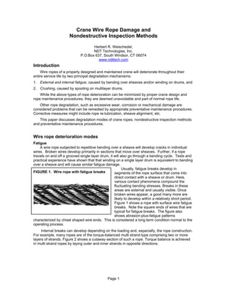
  • 1. Crane Wire Rope Damage and Nondestructive Inspection Methods Herbert R. Weischedel, NDT Technologies, Inc. P.O.Box 637, South Windsor, CT 06074 www.ndttech.com Introduction Wire ropes of a properly designed and maintained crane will deteriorate throughout their entire service life by two principal degradation mechanisms: 1. External and internal fatigue, caused by bending over sheaves and/or winding on drums, and 2. Crushing, caused by spooling on multilayer drums. While the above types of rope deterioration can be minimized by proper crane design and rope maintenance procedures, they are deemed unavoidable and part of normal rope life. Other rope degradation, such as excessive wear, corrosion or mechanical damage are considered problems that can be remedied by appropriate preventative maintenance procedures. Corrective measures might include rope re-lubrication, sheave alignment, etc. This paper discusses degradation modes of crane ropes, nondestructive inspection methods and preventative maintenance procedures. Wire rope deterioration modes Fatigue A wire rope subjected to repetitive bending over a sheave will develop cracks in individual wires. Broken wires develop primarily in sections that move over sheaves. Further, if a rope travels on and off a grooved single layer drum, it will also go through a bending cycle. Tests and practical experience have shown that that winding on a single layer drum is equivalent to bending over a sheave and will cause similar fatigue damage. Usually, fatigue breaks develop in FIGURE 1. Wire rope with fatigue breaks segments of the rope surface that come into direct contact with a sheave or drum. Here, various contact phenomena compound the fluctuating bending stresses. Breaks in these areas are external and usually visible. Once broken wires appear, a good many more are likely to develop within a relatively short period. Figure 1 shows a rope with surface wire fatigue breaks. Note the square ends of wires that are typical for fatigue breaks. The figure also shows abrasion-plus-fatigue patterns characterized by chisel shaped wire ends. This is considered a long term condition normal to the operating process. Internal breaks can develop depending on the loading and, especially, the rope construction. For example, many ropes are of the torque-balanced multi strand type comprising two or more layers of strands. Figure 2 shows a cutaway section of such a rope. Torque balance is achieved in multi strand ropes by laying outer and inner strands in opposite directions. Page 1
  • 2. FIGURE 2. In single fall operations the use of non-rotating ropes is mandatory. Multi strand This type of rope construction limits axial rotation of the freely suspended rope construction rope under load. In addition, multi strand ropes offer flexibility and a wear resistant surface profile. However, the wires and strands in different layers of these ropes touch locally and at an angle. Therefore, when multi strand ropes bend over sheaves or on a drum, they are subject to the combined effect of radial loading, relative motion between wires and bending stresses. This causes inter strand nicking (Figure 3) and, eventually, fretting wear or fatigue across the interface between layers as illustrated by Figure 4. Therefore, multi strand ropes are prone to develop internal broken wires. As indicated in Figure 5, this breakup occurs primarily on the interface between the outer and second layer of strands, usually with no externally visible signs. Wires in the second layer of strands typically show inter strand nicking and breaks caused by a combination of fluctuating axial wire stresses, inter-wire motions and fluctuating radial loads. The broken wires usually have squared-off and z-shaped ends that are typical for fatigue breaks. FIGURE 5. Typical FIGURE 3. Inter strand FIGURE 4. Broken wires in positions of broken nicking second layer of strands wires in multi strand ropes Typical positions of broken wires For example, on overhead traveling cranes, wire rope drums are generally single layer and spirally grooved. The rope passes over one and perhaps several sheaves. As there is no multi- layering on the drum involved, failure of the rope is usually by accumulated internal damage and fatigue rather than by wear and damage to external wires. Fatigue failure commences internally in areas where layers of the wire strands are in contact with each other. Since deterioration of non-rotating rope is not easily detected, failure of the rope is often unexpected. Page 2
  • 3. FIGURE 6. Typical IWRC rope Similar nicking and fatigue patterns occur in IWRC (Independent Wire Rope Core) ropes. Figure 6 shows a typical cross-sectional diagram of such a rope.1 For IWRC ropes, the outer wires of the outer strands have a larger diameter than the outer core strand wires. To minimize inter strand nicking between the outer strands and the IWRC, these ropes are designed such that the wires of the outer strands and the IWRC are approximately parallel. (This is usually achieved by choosing a lang lay construction for the IWRC and an ordinary lay construction for the outer strands.) IWRC Typically, the wires of the outer strands are well supported by their neighbors while the outer wires of the IWRC are relatively unsupported. The result of these geometrical features is that, under fluctuating tensile loads, the outer IWRC wires are continuously forced into the valleys between the outer strand wires and then released. This mechanism results in secondary bending stresses leading to large numbers of core wires with fatigue breaks. These breaks can be very close together and can form groups of breaks. Eventually, the IWRC can break, or it can even completely disintegrate into short pieces of wire about half a lay length long. This condition is commonly called complete rope core failure. As the IWRC fails, the outer strands lose their radial support. This allows the wires of the outer strands to bear against each other tangentially. The resulting inter strand nicking restricts the movement of the strands within the rope. Without this freedom of movement, secondary fatigue breaks in the wires of the outer strands will develop at the strand tangent points. Because these fatigue breaks develop in the valleys between the outer strands, they are also called valley breaks (Figure 7). FIGURE 7. Valley breaks In more general terms and paradoxically, internal broken wires occur frequently in ropes that, for safety reasons, are operated with large diameter sheaves and high factors of safety. Further, when a reeving system includes sheaves lined with plastic or all plastic sheaves, these sheaves offer more elastic support than steel sheaves. Then, the pressure between outer wires and the sheave grooves can be reduced to such an extent that, for some rope constructions, the first wire breaks will occur internally. Spooling on multi layer drums2 If a rope section travels on and off a grooved multi layer drum, it goes through a bending cycle. Rope sections spooling in the first layer are bent around a smooth drum surface. When the second layer comes in, rope sections in the first layer will be spooled over, compressed and damaged on the upper side by the second rope layer. Rope sections spooling in the second and higher layers will be damaged on all sides during contact with the neighboring wraps. In addition, they will bend around the very rough surface created by the previous rope layer, leading to additional wire damage. It is obvious that by these mechanisms the rope will be damaged far more than by just one bend on a single layer drum. The point where the rope is squeezed between the drum flange and the previous wrap, as it rises to form the next layer, is an area of accelerated wear. Typically, the slap of the rope at the crossover points can cause peening, martensitic embrittlement and/or wire plucking with the associated rope damage as the rope crosses over from layer to layer on a drum. Further, if the Page 3
  • 4. lower layers were not spooled under sufficiently high tension, the lower wraps can be displaced by the incoming rope section, allowing it to slide down between them. This can lead to severe rope damage. Various types of rope damage caused by drum winding are shown in Figure 8. FIGURE 8. Rope damage caused by multi layer drum winding Wire rope inspection and retirement Two different philosophies have been used to effect rope retirement: 1. A Statutory Life Policy mandates rope retirement at certain prescribed intervals. (This means, the Statutory Life Policy places a maximum on the time a rope can be in service). 2. Retirement for Cause is based on retirement conditions that are evaluated periodically by nondestructive inspections. (This means, the Retirement-for-Cause approach requires that the rope must be retired when the deterioration exceeds a certain limit.) Because a Statutory Life Policy is inherently wasteful, regulators have tended to adopt the Retirement-for-Cause approach wherever appropriate. Wire rope deteriorates gradually throughout its entire service life. To keep abreast of deterioration, wire rope must be periodically inspected. Because moderate deterioration is normally present, the mere detection of rope deterioration does not usually justify rope retirement. The purpose of wire rope inspections is to monitor the normal process of deterioration so that the rope can be retired before it becomes dangerous. Another benefit of inspection procedures is to detect unexpected damage or corrosion. There are two major nondestructive inspection methods for the detection and evaluation of rope degradation: Visual inspections and EM inspections. Page 4
  • 5. Visual Inspection The rag-and-visual method is a simple yet useful method for detecting a wide variety of external rope deteriorations. Using this approach, the inspector lightly grasps the rope – which moves at inspection speed – with a rag or cotton waste. External broken wires will often porcupine and, as the rope moves, snag the rag or cotton waste. The rope is then stopped at that point, and the inspector assesses the rope condition by a visual examination. Frequently, broken wires do not porcupine. Then, a different test procedure must be used. The rope is moved two or three feet at a time and visually examined at each stop. This method is tedious and, because the rope is often covered with grease, many external and internal defects elude detection. Another visual inspection tool is measurement of the rope diameter. Rope diameter measurements compare the original diameter – when new and subjected to a known load – with the current reading under like circumstances. A change in rope diameter indicates external and/or internal rope damage. Inevitably, many sorts of damage do not cause a change of rope diameter. Several visible signs can indicate distributed losses of metallic cross-sectional area, due to corrosion, abrasion and wear. For example, corrosion products, flattening of outer wires and loss or, sometimes, increase of rope diameter frequently reveal external and internal corrosion. However, the extent of corrosion is often difficult to gauge and its significance is even more difficult to assess. Visual inspections are inherently not well suited for the detection of internal rope deterioration. Therefore, they have limited value as a sole means of wire rope inspection. However, visual inspections are simple and do not require special instrumentation. When combined with the knowledge of an experienced rope examiner, visual inspection can provide a valuable supplementary tool for evaluating many forms of rope degradation. Electromagnetic Inspections EM wire rope inspection gives detailed insight into the condition of a rope. Its reliability has made EM testing a universally accepted method for the inspection of wire ropes in mining, for ski lifts, and many other applications. Two distinct EM inspection methods have evolved to detect and classify defects of the LMA and LF type. • Localized-Flaw Inspection (LF Inspection). Like the rag-and-visual method, LF inspection is suited only for the detection of localized flaws, especially broken wires. Therefore, small hand- held LF instruments have been called electronic rags. • Loss-of-Metallic-Area Inspection (LMA Inspection) detects and measures changes of the metallic cross-sectional area caused by wear and corrosion. More reliable than visual diameter checks, LMA inspection can replace diameter measurements made with a caliper. Therefore, LMA instruments could be called electronic calipers. Electromagnetic and visual wire rope inspections complement each other. Both are essential for safe rope operation, and both methods should therefore be used for maximum safety. The thrust of evolving regulations is clearly toward combined periodic EM and visual inspections Page 5
  • 6. A thorough inspection must consider all aspects of a rope's condition, including: 1. the findings of a visual inspection, 2. the results of an EM rope inspection, 3. the rope's operating conditions and related damage mechanisms, 4. the history of the rope under test and that of its predecessors. A program of periodic inspections is especially effective. To establish baseline data for subsequent inspections, such a program should commence with an initial inspection of the installed rope after a certain break-in period. Subsequent inspections should then be performed at scheduled intervals. In particular, periodic EM inspections allow the documentation of a rope's deterioration over its entire service life. Inspection of ropes that develop internal broken wires, especially non-rotating multi strand ropes Under normal operating conditions, multi strand ropes that wind on a single layer drum pose a particularly difficult inspection problem. As pointed out previously, this type of rope usually fails from fatigue. Inter wire nicking and fatigue breaks occur internally, usually at the interface between the outer and second layer of strands. Fatigue breaks of wires occur without any visible indications, which makes visual inspections ineffective. Since visual inspections are ineffective, a statutory life policy for rope retirement is usually adopted for multi strand ropes. This means that wire ropes are often discarded long before the end of their useful service life, and, literally, tens of millions dollars’ worth of expensive and perfectly good wire rope is discarded annually. At the same time, this wasteful and overcautious approach by no means assures wire rope safety. Following some slightly twisty reasoning, it has even been suggested that non-rotating rope should not be used if cranes use single layer winding on a drum. According to this way of thinking, multi strand ropes should be used only when winding on multilayer drums. Then, broken wires on the surface of the rope caused by wear, scrubbing or pulling in from one layer to the next begin to develop. As this damage is visible and progresses faster than the accumulation of internal wire damage, these non-rotating ropes are usually replaced because of external damage, long before they can fail due to internal fatigue.3 In cases where internal broken wires are a problem, electromagnetic rope testing can offer a solution. There are, however, some details that must be considered. Regulations usually require rope retirement when the number of broken wires per unit of rope length (e.g., lay length or 10 times rope diameter) exceeds certain limits. The discard numbers of wire breaks specified in retirement standards refer solely to external wire breaks. Appraising the condition of a wire rope with internal breaks is therefore left to the inspector. It would behoove him to discard a wire rope when the maximum total number of external and internal wire breaks per unit of rope length reaches the discard number specified in the standards. On the other hand, the detailed detection and quantitative characterization of internal broken wires in ropes with many breaks and clusters of breaks pose problems. Difficulties are caused by the fact that, for electromagnetic wire rope inspections, the indication of a broken wire is influenced by a number of parameters like a) broken wire cross-sectional area, b) broken wire gap width, and c) the position of the broken wire within the cross-section of the rope. d) For clusters of broken wires, an additional problem is caused by the fact that the relative position of broken wires with respect to each other along the length of the rope is not known. For example, the gaps of broken wires could be aligned or staggered. e) Finally and most importantly, broken wires with zero or tight gap widths are not detectable by electromagnetic inspections because they do not produce a sufficient magnetic leakage flux. Page 6
  • 7. Considering the above, only an estimate of the number of broken wires is possible. Conventionally, the LF trace is used for the detection of broken wires. However, the LF signal is not quantitative and cannot be used for estimating the number of internal broken wires per unit of rope length. Conversely, if many internal broken wires are present, the LMA trace will show rapid relatively small variations of cross-section. These variations are significant and can be used to estimate the number of broken wires per unit of rope length. Note, however, that the averaging length or quantitative resolution of the instrumentation used must be sufficient to allow this quantitative defect characterization. Round robin tests have shown that only very few rope testers offer the superior performance and sufficient LMA resolution required for solving this rather difficult defect characterization problem. Most rope testers failed at this problem, some of them miserably.4 Example 1. Experimental multi strand rope inspection4 This experimental inspection, performed with an LMA-175 rope tester from NDT Technologies, Inc., illustrates the use of EM wire rope inspections for the detection and quantitative characterization of internal broken wires and clusters of broken wires. The present experiment deals with the inspection of a torque balanced multi strand rope with no corrosion and many broken wires. This rope has been used as a mine hoist rope on a trial basis and was known to contain numerous internal broken wires along its entire length. The present experiment has particular value because the rope was disassembled after the inspection, which allows a correlation between the estimate and the actual number of broken wires. The task at hand was to determine the number of broken wires in 100 mm segments along the length the rope. The difficulty of this quantitative defect characterization problem was compounded by the fact that an undamaged rope section – usually the segment directly above the conveyance – was not available for comparison. Further, at the time, the correlation of the typical deterioration modes of this and similar ropes with their EM inspection results was generally not well understood. A cross-sectional diagram of this multi strand rope is shown in Figure 5. As indicated in the figure, it is known that broken wires in multi strand ropes usually develop in the second layer at the interface between the first and the second layer of strands. In addition, from this and similar ropes’ service histories, it can be assumed that the rope under inspection has developed significant inter strand nicking together with numerous fatigue breaks of wires in the second layer of strands. The estimated number of broken wires per 100 mm of rope length, N, derived from the LMA trace, is shown on the top of Chart 9. Here, Nmax denotes the maximum number of broken wires per 100 mm of rope length. Based on the operating history of this and similar ropes, a value of Nmax = 20 can be estimated. The rope was subsequently disassembled to determine the actual number of broken wires per unit of rope length. Broken wire estimates together with the actual number of broken wires along the length of the rope are shown in Figure 10. Considering the fact that the LMA trace not only indicates broken wires but also inter strand nicking, internal wear and other disturbances of the rope structure, there is a good correlation between the actual and estimated number of internal broken wires. The correlation between actual and estimated number of broken wires up to a rope distance of about 4500 mm is very good. Beyond this distance, there is an offset, which is probably due to a distance measurement error during disassembly of the rope. Page 7
  • 8. FIGURE 9. LMA and LF traces and relative number of broken wires Distance (meter from marker) -5 -4 -3 -2 -1 0 1 2 1 5 Relative Number of Broken Wires (N/Nmax) N/Nmax 4 0 3 Change of Cross-Section(%) High-Pass Filtered 2 -1 1 0 LF -2 -1 FIGURE 10. Broken wires at 100 mm intervals (smoothed data, 3 sample average) 14 12 Number of Broken Wires per 100 mm Interval 10 8 6 4 2 Actual Estimate 0 00 00 00 00 00 00 00 00 00 00 00 00 00 00 00 0 0 50 10 15 20 25 30 35 40 45 50 55 60 65 70 75 80 Distance on Rope (mm) A destructive break test of the rope showed a 30.2% loss of breaking strength. On the other hand, the second layer of strands of the rope (see Figure 5) represents about 30% of the total rope cross-sectional area. This leads to the hypothesis that, for this rope, the second layer of strands has lost all load-bearing capability. The lack of sufficient information on the rope’s operating history – and that of its predecessors – made this rope evaluation particularly difficult. Under normal circumstances, these details are known and must be considered when assessing the rope condition. Altogether, this evaluation shows that a quantitative defect characterization for ropes with internal broken wires and clusters of broken wires is possible. The example illustrates the capabilities and limitations of EM wire rope inspection methods for this particular defect characterization problem. Page 8
  • 9. Note, however, that data interpretation can become routine as soon as the correlation between test results and the actual rope condition has been established for different rope categories. Example 2. Inspection of IWRC (Independent Wire Rope Core) wire rope FIGURE 11. Inspection chart of IWRC rope with severe core damage LMA Trace LF Trace Figure 11 shows the results of an IWRC rope inspection (Figure 6). The chart recording indicates a severe breakup of the independent wire rope core. As previously discussed, this is strong evidence of heavy fluctuating tensile fatigue loading. Note that the LMA and LF traces show the typical patterns of broken and missing wires. The missing wire patterns even indicate that short pieces of broken IWRC wires might have fallen out of the rope. In addition, together with the findings of a visual inspection, the chart together with a visual inspection indicates severe corrosion, including corrosion pitting. Inspection of ropes that spool on multi layer drums As discussed above, winding-on-drum damage is usually external and can be detected by visual inspections. However, in spite of their conceptual simplicity, visual inspections are by no means easy and require a well qualified and experienced inspector. Under all conditions, an electromagnetic inspection will greatly enhance the accuracy and reliability of inspections. In addition, dependable inspection procedures, using combined visual and EM methods, can detect rope deterioration at its earliest stages. Therefore, wire rope users can employ them as an effective preventive maintenance tool. To illustrate, here are some practical examples. 1. The early detection of corrosion allows immediate corrective action through improved lubrication. 2. Accelerating wear and inter strand nicking can indicate a need to reline sheaves to stop further degradation. 3. Careful inspections can monitor the development of local damage at the crossover points of the rope on a winch drum. This way, the operator can determine the optimum time for repositioning the rope on the drum. Example 3. Winch rope inspection5 This locked coil rope was mounted on a mobile winch for approximately 10 years after 3 months earlier use on a friction winder installation. Its cross-sectional diagram is shown as part of Figure 12. The rope showed clear evidence of external corrosion, variable along the test length. Using retirement criteria that are appropriate for visual inspections, this rope would have been rejected for further use. Due to its service history the rope was not believed to contain any internal local defects. Page 9
  • 10. Examination after dismantling. After dismantling, the rope showed severe corrosion on the outer layer and also significant corrosion on the second layer. The third layer showed less corrosion, and from the fourth layer onward the rope appeared undamaged, because lubricants were still present. No local defects were found. FIGURE 12. Chart of winch rope inspection Distance (meter) 0.00 2.00 4.00 6.00 8.00 10.00 12.00 14.00 16.00 18.00 20.00 22.00 24.00 2 10 0 8 -2 Calibration Wire 6 LMA (%) 32 mm Locked -4 4 LF Coil Rope Typical Winding-on-Drum Damage -6 2 -8 0 -10 -2 Findings of electromagnetic inspection. Figure 12 shows an EM inspection chart of this rope. The maximum measured LMA is 5.1% compared to the best section on the rope covered by the chart. Note that the most convenient calibration method for EM inspections is to attach a calibration wire with known cross-sectional area to the rope. In the present case a wire bundle that represents about a 1% increase in rope cross-section was taped to the rope and used for calibration. This is indicated in the chart of Figure 11. The chart shows variable corrosion, corrosion pitting and, possibly, broken wires. As discussed previously, the slap of the rope at the crossover points can cause peening, martensitic embrittlement and/or wire plucking with the associated rope damage as the rope crosses over from layer to layer on a drum. The deterioration pattern indicated to the left of the chart is typical for ropes that wind on a drum with the worst deterioration occurring at the crossover points as the rope slips from layer to layer while winding on a multilayer drum. Page 10
  • 11. Example 6. Diving bell rope inspection FIGURE 13. Chart of diving bell hoist rope 60 65 70 Distance (m) LMA Trace LF Trace Figure 13 shows an EM inspection chart recording of a 30 mm die-formed multistrand diving bell hoist rope. When using non-rotating diving bell ropes, there are normally several layers of rope on the drum. The slap of the rope as it crosses over from layer to layer on the drum can cause peening, martensitic embrittlement and/or wire plucking with the associated damage. This rope shows periodic groups of broken wires at these cross-over points. This damage is visible. Usually, the external deterioration progresses faster than the internal wire fatigue damage that is typical for multi strand ropes. Therefore, many non-rotating ropes that are wound on drums are replaced because of external damage, long before they will fail due to internal wire fatigue. However, the possibility of internal fatigue damage should always be considered for these ropes. The maximum LMA for the rope under test is 1%. The rope section shown is subjected to the full in-air weight as the bell is lowered and raised. On the basis of the EM inspection, a decision was made to cut and re-terminate the rope behind the first defect about 58 m from the diving bell. Summary and Conclusion Combined with visual inspections, electromagnetic inspections can greatly increase the accuracy and reliability of crane rope examinations. This is especially true for ropes that develop internal broken wires such as torque balanced multi strand ropes and IWRC ropes. Combined visual and EM inspections can also be used as a powerful preventative maintenance tool. Altogether, the use of EM inspections promises improved crane safety. In addition, EM inspections are an effective preventative maintenance tool that promises considerable cost savings. REFERENCES 1. Wire Rope Users Manual, Third Edition. Woodstock, MD: Wire Rope Technical Board (1993). 2. Verreet, R. “Wire rope damage due to bending fatigue and drum crushing,” O.I.P.E.E.C. (International Organization for the Study of the Endurance of Wire Rope) Bulletin 85, June 2003, Reading (UK), ODN 0738, pp. 27-46. 3. Queensland Division of Workplace Health and Safety, “Non-rotating hoist wire ropes, multi fall configurations, Health and Safety Alert,” http://www.whs.qld.gov.au/alerts/97-i-5.pdf 4. Dohm, M. An evaluation of international and local magnetic rope testing instrument defect detection capabilities and resolution, particularly in respect to low rotation, multilayer rope constructions. Project Number GAP 503 and GAP 353. Johannesburg, South Africa: Safety in Mines Research Advisory Committee (1999), pp. 36-59 (Download from http://www.simrac.co.za, select "Reports" then " Machinery and Transportation Systems" then Report "GAP 503" 5. Smith, D.T. and P. McCann. Evaluation of Instruments for the Non-Destructive Testing of Wire Ropes. Report Number FE/02/07. Buxton, Derbyshire. UK: Health & Safety Laboratory (2002) Page 11