
Recomendados
Recomendados
Mais conteúdo relacionado
Mais procurados
Mais procurados (16)
Destaque
Destaque (9)
Semelhante a Shreyas, Yujin Chang-Heat Transfer through a Condensate Droplet on Hydrophobic and Nanostruct...
Semelhante a Shreyas, Yujin Chang-Heat Transfer through a Condensate Droplet on Hydrophobic and Nanostruct... (20)
Shreyas, Yujin Chang-Heat Transfer through a Condensate Droplet on Hydrophobic and Nanostruct...
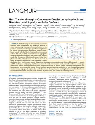
- 1. Heat Transfer through a Condensate Droplet on Hydrophobic and Nanostructured Superhydrophobic Surfaces Shreyas Chavan,† Hyeongyun Cha,†,‡ Daniel Orejon,‡ Kashif Nawaz,§ Nitish Singla,† Yip Fun Yeung,† Deokgeun Park,† Dong Hoon Kang,† Yujin Chang,† Yasuyuki Takata,‡ and Nenad Miljkovic*,†,‡ † Department of Mechanical Science and Engineering, University of Illinois, Urbana, 61801, United States ‡ International Institute for Carbon Neutral Energy Research (WPI-I2CNER), Kyushu University, 744 Motooka, Nishi-ku, Fukuoka 819-0395, Japan § Heat Transfer Center of Excellence, Johnson Controls, Norman, 73069 Oklahoma, United States *S Supporting Information ABSTRACT: Understanding the fundamental mechanisms governing vapor condensation on nonwetting surfaces is crucial to a wide range of energy and water applications. In this paper, we reconcile classical droplet growth modeling barriers by utilizing two-dimensional axisymmetric numerical simu- lations to study individual droplet heat transfer on nonwetting surfaces (90° < θa < 170°). Incorporation of an appropriate convective boundary condition at the liquid−vapor interface reveals that the majority of heat transfer occurs at the three phase contact line, where the local heat flux can be up to 4 orders of magnitude higher than at the droplet top. Droplet distribution theory is incorporated to show that previous modeling approaches underpredict the overall heat transfer by as much as 300% for dropwise and jumping-droplet condensation. To verify our simulation results, we study condensed water droplet growth using optical and environmental scanning electron microscopy on biphilic samples consisting of hydrophobic and nanostructured superhydrophobic regions, showing excellent agreement with the simulations for both constant base area and constant contact angle growth regimes. Our results demonstrate the importance of resolving local heat transfer effects for the fundamental understanding and high fidelity modeling of phase change heat transfer on nonwetting surfaces. ■ INTRODUCTION Water vapor condensation is routinely observed in nature and has a large influence on the performance of engineered systems such as building environmental control,1−3 power generation,4 and high-heat-flux thermal management.5 Previous studies have shown that water vapor condensation on hydrophobic surfaces can achieve up to 5−10× enhanced condensation heat transfer performance when compared to hydrophilic surfaces, due to the formation and rapid removal of discrete condensate droplets from the surface via gravity (shedding).6−10 The former, termed “dropwise” condensation,11 has been the topic of vigorous investigation since its discovery eight decades ago.11 With the aim of further enhancing droplet shedding, researchers have recently developed ultralow adhesion super- hydrophobic surfaces,12,13 and discovered that when micro- droplets (∼10−100 μm) condense and coalesce on these surfaces, the resulting droplet can jump away from the surface irrespective of gravity due to surface-to-kinetic energy trans- fer.14−19 This phenomenon has been termed jumping-droplet condensation and has been shown to further enhance heat transfer by up to 30% when compared to dropwise condensation.20 A number of works have since fabricated superhydrophobic nanostructured surfaces to achieve sponta- neous droplet removal21 for a variety of applications including self-cleaning,22−24 thermal diodes,25 anti-icing,26−29 vapor chambers,30 electrostatic energy harvesting,31−33 and con- densation heat transfer enhancement.34−45 Although experimental studies of dropwise and jumping- droplet condensation on superhydrophobic surfaces have advanced significantly over the past decade, modeling of the heat transfer process has lagged. Specifically, individual droplet heat transfer dynamics are poorly understood and cannot be computed accurately by using the simplifying assumption of constant temperature boundary conditions on the droplet base (solid−liquid interface) and free surface (liquid−vapor inter- face).6,8,20,37,39,46−51 First identified 50 years ago,52 this discrepancy has been reconciled via detailed three-dimensional simulations of droplets residing on hydrophilic surfaces (15° < θa < 90°) by assuming a convective boundary condition with a finite heat transfer coefficient on the free surface.53−55 However, little attention has been paid to droplets growing on hydrophobic (90° < θa < 150°) or superhydrophobic (150° Received: May 18, 2016 Revised: July 6, 2016 Published: July 13, 2016 Article pubs.acs.org/Langmuir © 2016 American Chemical Society 7774 DOI: 10.1021/acs.langmuir.6b01903 Langmuir 2016, 32, 7774−7787
- 2. < θa < 180°) surfaces from a simulation standpoint. Given the recent discovery and the great potential of jumping-droplet condensation, work is needed to study droplet condensation heat transfer on superhydrophobic substrates having advancing contact angles greater than 90°. In this work, we develop a two-dimensional (2D) axisymmetric numerical simulation of the individual droplet heat transfer on hydrophobic and superhydrophobic surfaces to study droplets of arbitrary contact angle (90° < θa < 170°). The local droplet heat flux and temperature are computed and expressions for the droplet Nusselt number as a function of the Biot number and apparent advancing contact angle are presented, showing excellent agreement with the previously derived analytical solution for hemispherical droplets (θa = 90°). Using our simulation results, we demonstrate that the majority of the heat transfer during condensation on super- hydrophobic surfaces occurs at the three-phase contact line, and that local heat transfer and temperature effects must be considered when computing condensation heat transfer through droplets residing on superhydrophobic surfaces due to their large interfacial temperature variation and minimal contact area with the substrate. To verify our simulations, we performed optical microscopy studies of water vapor condensation in the presence of noncondensable gases on macroscopically biphilic copper samples having simultaneous hydrophobic (θa ≈ 140°) and superhydrophobic (θa ≈ 170°) droplet morphologies. To elucidate the effects of non- condensables, we also performed environmental scanning electron microscopy (ESEM) of water vapor condensation on superhydrophobic (θa ≈ 170°) and hydrophobic (θa ≈ 120°) surfaces. The numerical simulations showed excellent agree- ment with the experimental results under identical super- saturations and for both constant basal area and constant contact angle growth regimes. The outcomes of this work elucidate the heat transfer physics governing individual droplet growth during vapor condensation on both hydrophobic and superhydrophobic surfaces that can be extended to the study of droplet-basal contact resistance on microstructured surfaces, droplet evaporation, and droplet freezing processes. ■ RESULTS AND DISCUSSION Model Development. To study the individual droplet heat transfer process of noncoalescing droplets, a 2D axisymmetric numerical model based on the finite element method was used to solve the heat equation through a single droplet (see Supporting Information, section S1). Although the droplet heat transfer process during condensation is exceedingly complex, some simplifying assumptions are possible from realizing that most of the heat is transferred through droplets of diameter less than 100 μm.37,56 For such small droplets the influence of gravity on the droplet shape is negligible and a spherical- segment geometry may be assumed (Figure 1). In addition, Marangoni and buoyant convection are neglected since the droplets are sufficiently small so that conduction is the dominant mode of heat transfer.57,58 Furthermore, the heat transfer and droplet growth are quasi-steady processes governed by the steady heat-conduction equation, ensuring that an analytic formulation can be completed with various boundary conditions.53 To reconcile the discontinuity associated with a constant free surface temperature, we assume a constant heat transfer coefficient boundary condition at the liquid−vapor interface (hi), and a constant temperature (Ts) boundary condition at the solid−liquid interface (Figure 1). Thus, there is no sudden temperature jump (discontinuity) across the three phase contact line, and the temperature will change gradually along the liquid−vapor interface. The liquid− vapor interface heat transfer coefficient is given by the interfacial condensation heat transfer coefficient, hi:59 α α π ν = − h R T h T 2 2 1 2 i g sat fg 2 g sat (1) where Rg is the specific gas constant and νg is the water vapor specific volume, Tsat is the water vapor saturation temperature, and hfg is the latent heat of condensation phase change. Since it is widely accepted that hi is independent of the interface location, we henceforth consider hi as constant along the liquid−vapor interface.52 The condensation coefficient α is the ratio of vapor molecules that will be captured by the liquid phase to the total number of vapor molecules reaching the liquid surface (ranging from 0 to 1). To study the effect of condensation coefficient on heat transfer, the model was simulated for different values of α (0.01, 0.04, and 1), representing both contaminated (α = 0.01) and clean (α = 1) environments.52 The condensate droplet is assumed to have a constant apparent advancing contact angle (θa). This assumption places constraints on the maximum structure length scale beneath the droplet since only nanostructured surfaces result in both (1) droplets with constant contact angle at an early stage of droplet growth (R ∼ 100 nm)15,37 and (2) negligible thermal resistance beneath the droplet.39 Hence, this assumption is well suited for droplets having radii bigger than 100 nm on smooth hydrophobic surfaces (90° < θa < 125°),10 as well as nanostructured superhydrophobic surfaces.20,37 Nondimensional analysis of the simulation parameters reveals three fundamental dimensionless groups governing the droplet heat transfer behavior (see Supporting Information, section S2). The individual droplet heat transfer, characterized by the droplet Nusselt number (Nu), is a function of the Biot number (Bi) and apparent advancing contact angle (θa); that is, Figure 1. Schematic of the simulation domain showing a condensate droplet with radius (R), base radius (Rb), and advancing contact angle (θa). The boundary conditions are (1) constant base (solid−liquid interface) temperature (Ts), (2) constant vapor temperature (Tsat), and (3) constant interfacial heat transfer coefficient (hi) at the free surface (liquid−vapor interface). The steady state heat conduction equation (▽2 T = 0) governs the heat transfer inside the 3D droplet, and Marangoni and buoyant convection are negligible due to the small droplet radii considered in these simulations. Langmuir Article DOI: 10.1021/acs.langmuir.6b01903 Langmuir 2016, 32, 7774−7787 7775
- 3. Nu = f(Bi,θa). Here, the Nusselt and Biot numbers are defined in terms of the droplet base radius (Rb) as53 =Bi h R k i b w (2) = − Nu Q k R T T( )w b sat s (3) where Q is the total heat transfer through the droplet and kw is the droplet thermal conductivity. The Biot number Bi is the ratio of thermal resistances inside of and at the surface of a body, while the Nusselt number Nu is defined as the ratio of convective to conductive heat transfer. To access a wide parameter space, numerical simulations were conducted for Ts = 90 °C, Tsat = 100 °C, 90° < θa < 170°, and 0.1 < Bi < 105 (corresponding to droplet base radii: 3.19 nm < Rb < 3.19 mm for α = 1). It is important to note that since the majority of heat is transferred through small droplets (<100 μm) during condensation we limit our analysis to Bi ≤ 100 (α = 1) for which the droplet radius falls below the capillary length of water at standard laboratory conditions (∼2 mm). Furthermore, although provided here, analysis results for droplets having both high Bi and θa should be used with caution since the resultant droplet may be physically much larger than the droplet capillary number and undergo breakup in real life prior to reaching such a large size. Model Results. Figure 2 shows the liquid−vapor interfacial temperature (Ti) and heat flux (q″) as a function of interface location (β) from the three phase contact line for (a, b) θa = 120° and (c, d) θa = 170°. Droplets having low Bi (Bi → 0.1, Rb → 157 nm for α = 0.04) showed smaller temperature gradients in the vicinity of the three phase contact line, that is, β < 5°, when compared to droplets with high Bi (Bi → 100, Rb → 157 μm for α = 0.04). A small condensation coefficient, α = 0.04 was used for these simulations to better display of gradient of Ti and q″ for a given Bi. The efficient heat transfer of small droplets results in higher vapor-to-free-surface temperature difference (Tsat − Ti) due to the low conduction pathway though the droplet itself (Qconduction = Qinterface ≈ hi(Tsat − Ti)), and hence lower temperature gradients. The interfacial heat flux (Figure 2b,d)) is very nonuniform and peaks at the three-phase contact line due to the efficient heat path from the liquid− vapor interface to the droplet base. Small droplets (Bi → 0.1) exhibited higher local heat fluxes when compared to their larger counterparts (Bi → 100) due to the low droplet conduction resistance, meanwhile larger droplets having elevated contact angles (θa → 180°) showed significant heat flux degradation due to the poor heat transfer characteristics caused by the limited droplet basal area (Figure 2d). The results show that the local heat flux can vary as much as 4 orders of magnitude from the three-phase contact line to the droplet top, indicating the importance of resolving the local heat transfer in order to obtain high fidelity results. It is worth noting that Bi is defined Figure 2. (a) Droplet interface temperature (Ti) and (b) local heat flux (q″) as a function of interface location (β) for different Biot numbers (0.1 < Bi < 100, corresponding to 157 nm < Rb < 157 μm, for α = 0.04), and advancing contact angles (θa) of (a,b) 120° and (c,d) 170°. A low condensation coefficient, α = 0.04 was used for these simulations to better display the gradient of Ti and q″ along the condensing interface for a given Bi. Inset of panels a and c: Droplet cross sectional temperature profile for droplets with Bi = 0.1 (droplets not to scale). Small droplets (Bi → 0.1) with low advancing contact angles (θa → 90°) have lower temperature gradients in the vicinity of the three phase contact line (β < 5°) when compared to large droplets (Bi → 100) with high advancing contact angles (θa → 180°). Furthermore, all droplets show elevated heat fluxes at the three-phase contact line (b,d) due to the low path for heat to travel from the liquid−vapor interface to the droplet base, suggesting the importance of understanding local heat transfer in order to obtain high fidelity results. The droplet curvature resistance (Kelvin effect) is not taken into account for these simulations. Langmuir Article DOI: 10.1021/acs.langmuir.6b01903 Langmuir 2016, 32, 7774−7787 7776
- 4. based on the droplet base radius Rb (eq 2), rather than the droplet radius R, hence droplets with identical Bi and differing θa have different droplet radii and heat transfer. It is also important to note that for the same droplet volume, the individual droplet heat transfer for low θa is greater than for high θa. A comparison of the droplet heat transfer as a function of θa for a fixed droplet volume is included in Figure S5 of the Supporting Information. To further quantify the droplet heat transfer, the simulation results were used to calculate the droplet Nusselt number (Nu, eq 3). Figure 3 shows Nu as a function of θa for different Bi. For small droplets (Bi < 5), Nu increases with increasing θa due to the low conduction resistance as well as higher interfacial heat transfer area associated with higher θa. However, for large droplets (Bi > 5), Nu decreases with increasing θa due to the elevated conduction resistance associated with higher θa, indicating that droplets with Bi < 5 are interface limited, while droplets having Bi > 5 are conduction limited. A comparison of the results shown in Figure 3 with those obtained by a previous study analyzing droplet heat transfer on a hydrophilic surface (0 < θa < 90°) using differential inequalities,53 shows excellent agreement at θa = 90°. It is also interesting to see that for Bi ≈ 5, the Nusselt number is almost invariant (Nu ≈ 8) with the advancing contact angle and, hence, experiments which are independent of θa can be performed. Furthermore, the constant Nu result indicates the critical droplet size for which the interfacial heat transfer resistance is approximately equivalent to the droplet con- duction resistance, which for the case of θa ≈ 170° equates to a droplet size of R ≈ 1 μm (for α = 1), in good agreement with previous experimental work identifying the growth regime crossover for conduction resistance on superhydrophobic surfaces.37 It is important to note that the heat transfer results relating Nu to θa and Bi (Figure 3) are universal and independent of condensation coefficient (α) and vapor-to-surface temperature difference (ΔT = Tsat − Ts). This behavior was expected since the Nusselt number (Nu), Biot number (Bi), and apparent advancing contact angle (θa) are the three dimensionless parameters that completely define the system. To provide the best fit estimate for Nu = f (Bi,θa), and to provide an analytical result that can more easily be integrated into droplet growth and phase change heat transfer models, the results of Figure 3 were fitted using the least-squares method to obtain the following expressions (θa is in radians) with a mean and maximum error of 4% and 23%, respectively: θ θ= + ≤− Nu Bi Bi Bi3 0.007 0.5a 0.65 0.83 a 5.1 0.23 (4) θ θ= + < ≤− − Nu Bi Bi Bi0.29 3.33 0.5 2a 2.24 0.17 a 0.3 0.72 (5) = + − < ≤ θ− Nu e Bi Bi Bi 5.76 ln(1 5 2.79 ) 2 10 0.28 0.82 0.83 5 a 0.68 (6) To account for the droplet vapor pressure increase with decreasing droplet size (increasing curvature)60 we altered the vapor-to-surface temperature difference in our numerical model. The vapor-to-surface temperature decrease due to droplet curvature is given by σ ρ Δ = − =T R R T T T Rh ( ) 2 c min sat s sat fg w (7) where Rmin is the critical nucleation radius for condensing droplets (∼10 nm for water at laboratory conditions),60 and σ and ρw are the condensate surface tension and density, respectively. Figure 4 shows Nu = f(Bi,θa) for the numerical Figure 3. Droplet Nusselt number (Nu = Q/(kwRbΔT)) as a function of apparent advancing contact angle (θa) for different Biot numbers (Bi = hiRb/kw). Least squares fitting (dashed-dot lines) are included for each Bi result. Small droplets (Bi < 5) show an increase in Nu with increased θa due to the larger interfacial area for heat transfer. Large droplets (Bi > 5) show a decrease in Nu with increased θa due to the larger conduction resistance through the droplet. For Bi ≈ 5, the Nusselt number is approximately constant (Nu ≈ 8), indicating the droplet size for which the interfacial heat transfer resistance is equivalent to the droplet conduction resistance (Rb ≈ 0.16 μm for α = 1). In the limit of θa = 90°, exact agreement is observed with the previous exact analytical solutions of Sadhal and Martin (red asterisks, ref 53). The droplet curvature resistance (Kelvin effect) is not taken into account in these simulations. Figure 4. Droplet Nusselt number (Nu = Q/(kwRbΔT)) as a function of apparent advancing contact angle (θa) for different Biot numbers (Bi = hiRb/kw) with and without droplet curvature resistance (Kelvin effect). Small droplets (Bi < 5) have higher temperature drop due to lower droplet radius of curvature, ΔTc = 2Tsatσ/Rhfgρw. At higher Bi (Bi > 5), the curvature resistance becomes negligible due to larger radii of curvature, and hence has little effect on Nu. Langmuir Article DOI: 10.1021/acs.langmuir.6b01903 Langmuir 2016, 32, 7774−7787 7777
- 5. simulation with and without the curvature resistance included. As observed from Figure 4, and Equation 7, the curvature resistance decreases as droplet size increases and becomes negligible for Bi ≥ 5 (Rb ≈ 160 nm for α = 1), hence its inclusion in the exact numerical simulation resulted in negligible changes in heat transfer behavior. To compare the results of our numerical simulation to the state-of-the art (SoA) analytical solutions,39,47 we define the overall droplet thermal resistance as Rt = (Tsat − Ts)/Q, where (Tsat − Ts) = 10 °C and Q is obtained from numerical simulation and analytical model. The droplet thermal resistance includes the interfacial heat transfer resistance due to the difficulty of isolating the droplet conduction resistance (nonconstant free-surface temperature). Figure 5 shows the numerical and analytical overall droplet thermal resistance as a function of θa for different Bi. Both the numerical and analytical solutions show excellent agreement at low Bi (Bi < 5) however the solutions deviate significantly as Bi increases (Bi > 5) due to the higher error associated with the analytical method for larger droplets. At low droplet radii (Bi < 5), the interfacial heat transfer resistance dominates both solutions, hence the good agreement observed. As the droplet radius increases (Bi > 5), the droplet growth becomes conduction limited and the discrepancy between the two methods becomes apparent. From a physical standpoint, the smaller thermal resistance of the numerical solution stems from its ability to capture local heat transfer effects at the three phase contact line. As shown in Figure 2, the three phase contact line acts as a heat transfer channel during condensation of large droplets (Bi > 5) due to the low heat diffusion distance. Currently used analytical approaches using conduction shape factor solutions cannot reconcile these details, resulting in low-fidelity results. To study the overall steady-state condensation heat flux, we combined the simulation results with droplet distribution theory to account for the fraction of droplets on the surface of a given radius R for surfaces undergoing gravitation shedding and jumping. For small droplets (R ≤ Re), the size distribution n(R) is determined by47 π = ̂ ̂ − − × + + + − ⎜ ⎟ ⎛ ⎝ ⎞ ⎠ n R R R R R R R R R R A R A A R A B B ( ) 1 3 ( ) exp( ) e 3 e 2/3 e min min 2 3 2 e 3 1 2 (8) where R̂ is the average maximum droplet radius (departure radius), Re is the radius when droplets begin to merge and grow by droplet coalescence, Rmin is the critical nucleation radius for condensing droplets (≈10 nm for water), and A2, A3, B1, and B2 are constants associated with droplet growth and sweeping (for detailed model explanation, see Supporting Information, section S3). For large droplets growing due to coalescence (R ≥ Re), the droplet distribution N(R) is determined from7 π = ̂ ̂ − ⎜ ⎟ ⎛ ⎝ ⎞ ⎠ N R R R R R ( ) 1 3 2 2/3 (9) where both n(R) and N(R) have the units of m−3 . The total surface steady state condensation heat flux (q″) is obtained by incorporating the individual droplet heat transfer rate obtained from simulations (eq 4 to 6), with the droplet size distributions (eq 8 and 9): ∫ ∫″ = + ̂ q Q R n R R Q R N R R( ) ( ) d ( ) ( ) d R R R R min e e (10) Figure 6 shows the steady-state condensation heat flux as a function of θa for dropwise and jumping-droplet removal mechanisms. For both the numerical and analytical solutions, increasing θa results in decreased heat transfer performance due to the formation of droplets which are more spherical and have higher conduction thermal resistances through them. Although experimentally, surfaces having elevated contact angles necessitate greater nonwetting and smaller contact angle hysteresis, the hysteresis was kept constant in these simulations to simplify the model. The jumping-droplet condensation heat transfer coefficient was ∼40% higher than that of dropwise condensation, in excellent agreement with previous exper- imental studies.61 Interestingly, a significant difference in the condensation heat flux can be observed between the analytical and numerical solutions. For dropwise condensation, the difference is as large as 300%, which stems from the inability of the analytical solution to capture the local heat transfer behavior at the three phase contact line. Furthermore, dropwise condensation is typified by the formation of large droplets (∼2 mm for water) prior to shedding, resulting in a considerable fraction of droplets having Bi > 5, where the analytical and numerical models have been shown to diverge (Figure 5). Conversely, the jumping droplet condensation results had a relatively smaller deviation between the analytical and numerical results due to jumping-droplet condensation having a large population of small microdroplets (∼10 μm) with Bi < 5, where the growth is interface limited and conduction Figure 5. Droplet thermal resistance (Rt = (Tsat − Ts)/Q) as a function of apparent advancing contact angle (θa) for different droplet Biot number (Bi = hiRb/kw) and condensation coefficient α = 1. The thermal resistance is from the vapor (Tsat) to the surface (Ts) and combines both the interfacial heat transfer resistance and the conduction resistance through the droplet. The combination of interfacial and conduction resistances was necessary due to the nonuniform free surface temperature (Ti). Both analytical (ref 47) and numerical (our work) values are provided. The analytical solution assumes a constant free-surface temperature with an approximate shape factor to compute the droplet thermal resistance:Rt,analytical = 1/ (2πR2 hi (1−cos θa) + θa/(4πRk sin θa)). The analytical and numerical results show good agreement for small droplets (Bi < 5) due to the negligible droplet conduction resistance in this regime. However, as droplets grow larger (Bi > 5), the discrepancy between the numerical and analytical results increases due to the growing influence of droplet conduction on droplet growth and heat transfer. Langmuir Article DOI: 10.1021/acs.langmuir.6b01903 Langmuir 2016, 32, 7774−7787 7778
- 6. resistance through the droplet, and three-phase contact line effects, are not as pronounced. ■ EXPERIMENTS Optical Microscopy Experiments. To verify the numer- ical results and compare them to the analytical model,47 we conducted droplet growth experiments of individual non- coalescing droplets on a biphilic surface composed of a smooth hydrophobic finish on one-half, and a rough nanoscale superhydrophobic coating on the other (Figure 7a). We chose to work with a single biphilic sample instead of two separate samples having distinct wettability in order to ensure identical local droplet growth conditions (local wall temper- ature and vapor pressure) in the viewing microscopy area (∼100 μm2 ). By observing and measuring the droplet growth rate at the interface between the two regions of differing wettability, we were able to capture droplet growth on both hydrophobic and superhydrophobic regions and ensure that the local supersaturation is the same. Furthermore, the use of a single biphilic sample resulted in identical parasitic thermal resistances, such as mounting thermal grease uniformity and sample thickness, for all droplets being measured. To create the biphilic sample, commercially available polished multipurpose 110 Cu tabs (25 mm × 2 25 mm × 0.8 mm) were used (99.90% purity). Each Cu tab was thoroughly rinsed with acetone, ethanol, isopropyl alcohol (IPA), and deionized (DI) water. The tabs were then dipped into a 5.0 M hydrochloric acid solution for 2 min to remove the native oxide film on the surface, then rinsed with DI water and dried with clean N2 gas. Nanostructured CuO films were formed by immersing the cleaned tabs into a hot (96 ± 3 °C) alkaline solution composed of NaClO2, NaOH, Na3PO4· 12H2O, and DI water (3.75:5:10:100 wt %).62 To ensure that only one-half of each tab was coated with the nanostructure, the tabs were oriented on their sides, and only dipped half way into the alkaline solution (Figure 7a). During the oxidation process, a thin (≈300 nm) Cu2O layer was formed on the dipped side that then reoxidized to form sharp, knife-like CuO oxide structures with heights of h ≈ 1 μm (Figure 7b). The nonimmersed side remained smooth with a tool-finish from sample processing (Figure 7c). To functionalize the surface, a proprietary fluorinated polymer was deposited using plasma enhanced vapor deposition (P2i). The process occurs under low pressure within a vacuum chamber at room temperature. The coating is introduced as a vapor and ionized. This process allows for the development of a highly conformal (∼50 nm thick) polymer layer, which forms a covalent bond with the surface (Figure 7b). Contact angle measurements (MCA-3, Kyowa Interface Science Ltd.) of ∼300 nL droplets on a smooth P2i-coated silicon wafer showed advancing and receding contact angles of Figure 6. Overall steady-state surface heat flux (q″) during condensation on a vertical wall as a function of apparent advancing contact angle (θa) for dropwise (shedding) and jumping-droplet condensation. For the jumping-droplet solutions, the roughness of the surface (r = total area/projected area) was assumed to be 25, corresponding to copper oxide nanostructures. Furthermore, jumping droplet results were only computed for θa = 150°, 160°, and 170° due to the need for suitably low solid fraction structures with minimal adhesion in order to ensure droplet jumping. The contact angle hysteresis (Δθ = θa − θr, where θr is the receding contact angle) was assumed to be 10° for the dropwise condensation results. The results indicate that elevated advancing contact angles lead to degraded performance for both the numerical and analytical solutions due to the elevated droplet conduction resistance. A large discrepancy (∼300%) exists between the numerical and analytical solutions due to the failure of the analytical solution to capture the important heat transfer details at the three-phase contact line. For a full derivation, see section S3 of the Supporting Information. Model parameters: condensation coefficient α = 1, vapor-to-liquid temperature difference ΔT = 10 °C. Figure 7. (a) Top view image of the biphilic sample with tool-finish hydrophobic (orange) and rough superhydrophobic (black) regions. A biphilic sample was chosen in order to ensure identical local droplet growth conditions: local wall temperature, vapor pressure, and therefore same local supersaturation. In addition it resulted in identical parasitic thermal resistances for all droplets being measured. Field emission scanning electron micrographs of (b) a 10 min oxidized nanostructured CuO surface coated with a ≈ 50 nm thick layer of P2i fluoropolymer and (c) tool-finish Cu surface coated with a ≈ 50 nm thick layer of P2i fluoropolymer. The sharp, knife-like CuO structures have characteristic heights, h ≈ 1 μm, and solid fraction, φ ≈ 0.04. The macroscopically measured advancing apparent contact angle on the tool-finish hydrophobic Cu and superhydrophobic CuO surfaces was θa app ≈ 146.0 ± 2.1° and θa app ≈ 170.5 ± 7.2°, respectively. (d) Schematic of the optical microscopy experimental setup used to study the growth rate of condensing water droplets. Droplet growth movies were recorded at 30 frames per second. Experimental conditions: stage and sample temperature Ts = 10, 5, and 0 ± 0.5 °C, ambient air temperature Tair = 22 ± 0.5 °C, vapor temperature Tv = Tsat(ΦPsat(Tair)) = 11.1 ± 0.5 °C, relative humidity Φ = 50 ± 1%, and supersaturation S = [ΦPsat (Tair)]/Psat (Tw) = 1.07 ± 0.035, 1.51 ± 0.052, 2.16 ± 0.085. Schematics not to scale. Langmuir Article DOI: 10.1021/acs.langmuir.6b01903 Langmuir 2016, 32, 7774−7787 7779
- 7. θa = 125.4 ± 2.9° and θr = 115.1 ± 3.8°, respectively. Using the values of the advancing contact angles on the rough (θa app ≈ 170.5 ± 7.2°) and smooth (θa = 125.4 ± 2.9°) P2i surfaces, we estimated the effective solid fraction of the CuO surface to be φ = (cos θa app + 1)/(cos θa + 1) ≈ 0.04. The functionalization of the whole surface resulted in ideal biphilic behavior with the tool-finish hydrophobic (Figure 7c) and rough superhydro- phobic (Figure 7b) regions showing advancing contact angles of θa ≈ 146.0 ± 2.1° and θa app ≈ 170.5 ± 7.2°, respectively. Droplet growth behavior was studied using a custom built top-view optical light microscopy setup shown diagrammati- cally in Figure 7d and substantially similar to the one described in ref 63. Briefly, samples were placed horizontally on the cold stage (Instec, TP104SC-mK2000A) with a thin film of water underneath in order to provide good thermal communication between the sample and stage. The cold stage was cooled to the test temperatures of Ts = 10, 5, and 0 ± 0.5 °C in a laboratory environment having air temperature, Tair = 22 ± 0.5 °C, and relative humidity (RH), Φ = 50 ± 1% (Roscid Technologies, RO120). Video recordings were performed at frame rates of 30 frames/s with a high speed camera (Phantom, V711, Vision Research) attached to an upright microscope (Eclipse LV100, Nikon) (Figure 7d). Top view imaging was performed with a 20X (TU Plan Fluor EPI, Nikon) objective (Figure 7d). For the 20X, lens, the working distance was measured to be 5 ± 0.5 mm. Illumination was supplied by an LED light source (SOLA SM II Light Engine, Lumencor). The LED light source was specifically chosen for its high-intensity and low power consumption (2.5 W) in order to minimize heat generation at the surface due to light absorption and minimize its influence on the droplet growth rates during condensation. Furthermore, by manually reducing the condenser aperture diaphragm opening size and increasing the camera exposure time, we were able to minimize the amount of light energy needed for illumination and hence minimize local heating effects during condensation experiments.64 Figure 8a and b show time lapse images of individual droplet growth on the superhydrophobic and hydrophobic regions, respectively, which highlights the relatively similar growth rates on the two surfaces. As the droplets grew and began to interact with each other on the superhydrophobic regions, removal via coalescence-induced droplet ejection was observed.14 Indeed, the sharp knife-like roughness features of the CuO structure act to both minimize the contact line pinning force, and ensure the formation of partially wetting droplets, ideal for enhanced condensation heat transfer.61,65 In addition, we examined the time lapse images of droplet growth to obtain the average droplet diameter, ⟨D⟩, as a function of time, t, for the superhydrophobic (Figure 8c) and hydrophobic (Figure 8d) areas. To provide insight into the experimental results, capture the growth dynamics related to the different droplet morphologies, and verify the numerical simulation results, we modeled the experimental droplet growth behavior with our developed simulations and the analytical model.47 To determine the theoretical growth rate (dD/dt = 2 dR/dt), the individual droplet heat transfer Q(R,θ) is related to the droplet growth rate by the latent heat of phase change39 Figure 8. Time lapse optical microscopy images of droplet growth during water vapor condensation on the (a) superhydrophobic region (θa app ≈ 170.5 ± 7.2°) and (b) hydrophobic region (θa app ≈ 146.0 ± 2.1°) of the biphilic sample (Figure 7a). The hydrophobic droplet growth has been false- colored blue for clarity. The biphilic surface was maintained at 5 °C prior to condensation. Time evolution of the average droplet diameter (⟨D⟩) on the (c) superhydrophobic and (d) hydrophobic regions. Inset: Schematics of the droplet morphology. At early stages (⟨D⟩ < 15 μm), rapid growth of superhydrophobic droplets results due to low conduction resistance through the droplet and high interfacial area. The presence of NCGs acts to decrease the effects of droplet heat transfer physics, and dominates the thermal resistance of the droplet growth by placing more emphasis on the external vapor diffusion resistance. Langmuir Article DOI: 10.1021/acs.langmuir.6b01903 Langmuir 2016, 32, 7774−7787 7780
- 8. θ ρ π ρ θ θ = ̇ = = − + Q R mh h V t h t R ( , ) d d 3 d d [(1 cos ) (2 cos ) ] fg w fg w fg 2 3 (11) Differentiating the terms in squared brackets on the right-hand- side of eq 11, we obtain an explicit term for dR/dt θ πρ θ θ θ θ θ = − + − + { } Q R h R R t R R( , ) d d (1 cos ) sin d d (1 cos ) (2 cos ) w fg 2 2 2 2 (12) The individual droplet heat transfer, Q(R,θ) = f(Ts,α,Psat), was computed using our simulation (black solid line in Figure 8c,d) and the analytical model (blue line in Figure 8c,d). When a water droplet nucleates and grows on the superhydrophobic surface, a varying contact angle is observed initially for D < 6−8 μm because of locally pinned contact lines at the droplet base.36 Thus, in order to simulate the growth of droplets on the superhydrophobic surface (Figure 8a), we used a band approximation for the advancing contact angle, with θa = 150° for D ≤ 7 μm, θa = 160° for 7 μm < D ≤ 14 μm, and θa = 170° for D > 14 μm, in agreement with previous well- characterized droplet growth studies during condensation on superhydrophobic CuO.36 For droplets growing on the hydrophobic surface, droplet contact angle variation as a function of droplet diameter was not observed, thus a constant θa = 140° was used for the models. The results of the numerical model (black solid line) are shown in Figure 8c,d and are in excellent agreement with the experiments (red circles). The analytical model (blue solid line in Figure 8c,d), however, tends to underestimate the experimental growth rate due to the lack of taking into account local heat transfer effects at the three-phase contact line. As observed in the experiments, the numerical model shows that for large droplet diameters (D > 15 μm), droplets growing on the superhydrophobic surface have slightly lower growth rates than a droplet on the hydrophobic surface due to the added conduction thermal resistance. While at low droplet diameters (D < 15 μm), the growth rate of the superhydrophobic droplets is faster due to interfacial thermal resistance dominated growth. The model solutions were obtained for surface-to-vapor temperature difference ΔTnumerical = ΔTanalytical = 0.0018 °C, where ΔT was chosen on the basis of the best fit between the numerical model and experimental growth rate data. The experimental surface-to-vapor temperature difference, ΔTexp = Tsat (ΦPsat (Tair)) − Ts = 6.1 ± 0.58 °C, was three orders of magnitude larger than the numerical temperature difference. The significant discrepancy between model and experiments can be attributed to the presence of noncondensable gases (NCGs). The condensation of water vapor acts to leave behind NCGs (air) that blanket the surface and act as a diffusion barrier for water vapor.66−68 The counter diffusion of water vapor to the surface, coupled with the diffusion of NCGs away from the surface, acts to significantly deteriorate the condensation heat transfer process, and hence decrease the effective surface-to-vapor temperature difference. Interestingly, previous analysis of filmwise condensation in the presence of NCGs showed temperature drops of similar orders of magnitude as observed in these experiments, with ∼2 °C happening in the vapor diffusion layer, and ∼0.01 °C occurring in the condensate film.69 As a secondary artifact, the presence of NCGs can be observed through the relatively large error bars in the droplet growth data (Figure 8c,d). Significant variability in individual droplet growth was observed based on the location of droplets relative to one another, with isolated droplets growing faster than droplets residing close to many neighbors. The droplet growth variability can also be attributed to the presence of NCGs, formation of vapor depletion layers, and concentration boundary layer overlap from droplet-to-droplet.70−72 To gain further insight, we compared the experimental results with the power law exponent model.72 When droplet dimensions are larger than the surface pattern length scales (⟨D⟩ > 1 μm, as observed here), droplets grow as breath figures on a surface with an expected average droplet diameter of ⟨D⟩ = Atμ , where μ, the power law exponent, ranges from 0 to 1 depending on the droplet, substrate dimensions, and growth limiting conditions. In these experiments, due to the presences of NCGs, we expect vapor diffusion limitations to dominate droplet growth dynamics. To determine if the vapor diffusion boundary layers of neighboring water droplets overlap, we calculated the boundary layer length scale given by73 ρ ε = Γ−R t D n R d d 12 w 1 0 (13) where D12 is mutual diffusion coefficient of water in air, ρw is the number density of water, Γ is a geometrical factor related to the contact angle θ, n0 is the average concentration of monomers established in the vapor medium, and ε is the length of vapor diffusion boundary layer. For the droplet growth experiments conducted here, the calculated vapor diffusion boundary layer thickness was greater than 10 mm for all cases (all droplet sizes on the superhydrophobic and hydrophobic regions of the biphilic surface). From exper- imental observations, the distance between neighboring droplets was found to be on the order of ∼100 μm. Thus, for adjacent water droplets the vapor diffusion boundary layers overlap. In the overlapping vapor diffusion boundary layer regime, a 2-D concentration gradient forms, whose typical length scale is of the order of R. Then the droplet grows as72,74 π π∼ ∼ ⎜ ⎟ ⎛ ⎝ ⎞ ⎠ V t R R t R R D d d 4 d d 2 12 12 (14) where, dV/dt is the water droplet growth rate. Rearranging eq 14 the following relationship D ∼ 2R ∼ t1/3 (μ = 0.3) is found for time scales when overlapping of the diffusion boundary layers dominates and a macroscale NCG layer blankets the surface. Interestingly, the experimental results of Figures 8c,d agree remarkably well with the scaling analysis, revealing that the droplet power law is obeyed by both superhydrophobic and hydrophobic surfaces with μSHP = 0.3, μH = 0.3 at early time scales. The power law results reinforce the critical importance that NCGs play in the dynamics of droplet growth and help clarify the similar growth rates and low model temperature differences needed to match the simulations to the experiments. Fitting of ΔT for the other experimental cases having Ts = 10, 5, and 0 °C yielded ΔT = 0.0015, 0.0018, and 0.0025 °C, respectively, in agreement with the fact that NCGs act to dominate the vapor and heat transport in these experiments. It is important to note that for all experiments, fitting with the Langmuir Article DOI: 10.1021/acs.langmuir.6b01903 Langmuir 2016, 32, 7774−7787 7781
- 9. same value of ΔT for both superhydrophobic and hydrophobic droplet growth yielded the best numerical model fit to the experimental results. The good agreement is due to our experimental ability to maintain the same local conditions (supersaturation) for both surfaces via the biphilic surface design. For additional experimental and model results at different supersaturations, please see Supporting Information, section S4. Perhaps the most interesting aspect of the optical microscopy studies, in addition to their ability to validate the numerical simulations, is that droplet jumping was observed on the superhydrophobic area for all macroscopically measured supersaturations, S = [ΦPsat (Tair)]/Psat (Ts) = 1.07 ± 0.035, 1.51 ± 0.052, and 2.16 ± 0.085. Contrary to previous studies on superhydrophobic CuO,61 nucleation mediated flooding due to saturation of nucleation sites on the surface at S > 1.12 was not observed in these experiments. The reason for the elevated critical supersaturation is attributed to the presence of NCGs, which were not present in previous studies. The results shown here point to the need to classify nucleation mediated flooding based on surface critical heat flux (qcr″ > 8 W/cm2 ) as opposed to the critical supersaturation (Scr ≈ 1.12), as identical macroscopic supersaturations in pure vapor environments and NCG environments yield strikingly different condensation, nucleation, and heat flux behavior. Environmental Scanning Electron Microscopy Experi- ments. To remove the effects of NCGs, we conducted droplet growth experiments in an environmental scanning electron microscope (ESEM; Versa 3D, FEI) that enabled observation of microscale water droplets at saturation vapor pressures of up to 4 kPa ± 0.2%. The removal of NCGs eliminated the dominant vapor diffusion resistance (not accounted for in the numerical or analytical model), enabled the principal thermal resistances governing droplet growth to come into play, and hence validate our model with higher accuracy. Prior to the experiments, a gas scanning electron detector (GSED) and a Peltier stage were mounted inside the ESEM chamber. Each sample substrate was attached to a 5 mm thick copper sample holder with carbon conductive tape and then mounted on the Peltier stage to control the temperature of the sample surface. The chamber was closed and pumped down to high vacuum mode (<1 mPa) to remove any contaminants or NCGs present in the chamber. Prior to condensation, the pressure in the ESEM chamber was maintained at <100 Pa and the surface temperature was set at 0 ± 0.1 °C. To ensure that the surface temperature matches the set temperature, the temperature was maintained for >10 min prior to condensing. Water vapor pressure in the chamber was gradually increased at 50 Pa/min until condensation appeared on the surface at saturation pressures ranging from 630 to 700 Pa. It is important to note, to ensure proper degassing of the water vapor supply, which consisted of a Erlenmeyer flask filled with liquid water connected via a software controlled valve, the chamber was cycled from condensation to dry out by initiating condensation Figure 9. Time lapse ESEM images of droplet growth during saturated water vapor condensation on the (a) superhydrophobic Al (θa app ≈ 170.5 ± 2.5°) and (b) smooth hydrophobic SiO2 (θa ≈ 115.5 ± 4°) samples, respectively. Time evolution of the average droplet diameter (⟨D⟩) on the (c) superhydrophobic and (d) hydrophobic samples. Inset: Schematics of the droplet morphology. The elimination of NCGs from the water vapor amplified the effects of interfacial and droplet conduction resistances. At later stages of growth (⟨D⟩ > 20 μm), the hydrophobic droplet growth rate is much faster than the superhydrophobic due to reduced droplet conduction resistance. For the analytical and numerical models, a vapor-to-surface temperature difference of ΔTnumerical = 0.01 °C was used to fit the experimental data. The experimental surface-to-vapor temperature difference, ΔTexp = Tv − Ts = 0.1 ± 0.1 °C, was in excellent agreement with the numerical temperature difference and within the error of the experimental apparatus. The removal of NCGs eliminated the dominant vapor diffusion resistance (not accounted for in the numerical or analytical model), enabled the principal thermal resistances governing droplet growth to come into play, and hence validate our model with higher accuracy. Langmuir Article DOI: 10.1021/acs.langmuir.6b01903 Langmuir 2016, 32, 7774−7787 7782
- 10. at an elevated pressure (typically 1200 ± 2.4 Pa), condensing for a full 2 min, reheating the stage to evaporate the condensed water, and pumping down to 50 ± 0.1 Pa to remove the evaporated vapor. By cycling the evaporation/pump-down cycle 10 times, we ensure that any NCG content in the vapor supply line has been removed and pumped out of the system. To minimize droplet evaporation as a result of heating by the electron beam, the voltage and current of the electron beam were set at 10 kV and <12pA, respectively, and a field of view of 120 × 86.5 μm2 . For similar ESEM viewing parameters, prior studies64 have shown negligible beam heating effects at viewing areas <4.6 × 4.3 μm2 . Our studies used a larger field of view (120 × 86.5 μm2 ), making it appropriate to neglect heating effects. Droplet growth videos were captured at one frame (768 by 556 pixels) every 2 s (dwell time per pixel ∼3 μs). For the ESEM experiments, boehmite nanostructures on aluminum and smooth silicon wafers functionalized with hydrophobic self-assembled monolayers of HTMS were used to obtain superhydrophobic and hydrophobic droplet mor- phologies, respectively. The change from copper (∼800 nm) to aluminum-based nanostructures (∼300 nm) does not alter the growth dynamics of condensing droplets due to the negligible thermal resistance of the partially wetted base for both surfaces. Smooth hydrophobic silicon was used instead of tool finish copper because of our desire to observe droplet growth behavior on lower advancing contact angle surfaces to investigate the robustness of our numerical model. To create superhydrophobic aluminum oxide samples, the technique given by ref 75 was used. Commercially available Al tabs (10 mm × 10 mm × 0.8 mm) were used (99.90% purity). Each Al tab was ultrasonically treated in acetone and then in ethanol for 5 min. The cleaned samples were dried in a clean N2 stream. The specimens were then immersed into hot deionized water (90 °C) for 1 h, followed by removal and rinsing with room temperature deionized water. This enabled boehmite (Al2O3) formation on the Al surface with sharp, knife-like structures having length scales approaching ∼300 nm. To functionalize the surfaces, heptadecafluoro- decyltrimethoxy-silane (HTMS) was deposited using vapor phase deposition. Nanostructured Al substrates were placed in a container with a vial of 1 mL of HTMS toluene solution (5% v/ v). A lid was placed on top to seal the container, and then the container was heated in an atmospheric pressure oven at 80 °C for 3 h. This process allows for the development of a highly conformal coating as the HTMS molecules evaporate from solution and redeposit on the aluminum samples. The same technique was used to coat HTMS on smooth silicon wafers, which were cleaned with acetone, IPA, DI water, and rinsed in clean N2 prior to functionalization. Contact angle measure- ments of ∼300 nL droplets on a HTMS-coated nanostructured Al surface showed advancing/receding contact angles of θa app / θr app ≈ 170.5 ± 2.5°/155 ± 7°. Smooth HTMS-coated silicon wafers showed advancing/receding contact angles of θa/θr = 115.5 ± 4°/107 ± 4°. Figure 9a,b show ESEM time lapse images of individual droplet growth on the superhydrophobic nanostructured aluminum surface and on the hydrophobic smooth silicon surface, which highlights the difference in droplet growth rate. Droplet growth on the surfaces was characterized at a water vapor pressure Pv = 700 ± 1.4 Pa, corresponding to a saturation temperature of 1.9 ± 0.004 °C, and a substrate temperature Ts = 1.8 ± 0.1 °C. The experimentally obtained droplet diameter as a function of time for superhydrophobic and hydrophobic morphologies are shown in Figure 9c,d, respectively. On superhydrophobic aluminum, scatter in the droplet growth data was almost nonexistent, with droplets growing, coalescing, jumping, and regrowing in a self-similar manner for each cycle. In addition, the droplet growth rate of adjacent droplets was also identical in nature. The lower variability in growth rate is attributed to the lack of NCGs in the ESEM environment. The vapor diffusion resistance is much smaller, and hence, droplet growth dynamics are limited mainly by interfacial resistance at early times, and conduction resistance at later times. To provide insight into the ESEM results and verify our simulations, we modeled the experimental droplet growth behavior with the numerical and analytical models according to eq 12. The results of the numerical model (black dashed line) are shown in Figure 9c,d and are in excellent agreement with the experiments. The removal of NCGs acted to accentuate the growth rate difference between the two droplet morphologies. As observed in the experiments, the numerical model shows that for large diameters (D > 20 μm), droplets growing on the superhydrophobic surface have lower growth rates (d⟨D⟩/dt = 0.06 μm/s) than droplets on the hydrophobic surface (d⟨D⟩/dt = 0.2 μm/s) due to the added conduction thermal resistance. While at low diameters (D < 20 μm), the growth rate of the superhydrophobic droplets (d⟨D⟩/dt = 1.0 μm/s) is much faster due to interfacial thermal resistance dominated growth. These same trends were observed in the optical microscopy results, however with lower growth rate difference between the two droplet morphologies arising from (1) the higher advancing contact angle of the tool-finish copper surface, and (2) the external vapor diffusion resistance, which acted to minimize growth differences due to morphology. The ESEM model solutions were obtained for surface-to-vapor temperature difference ΔTnumerical = ΔTanalytical = 0.01 °C, where ΔT was chosen based on the best fit between the numerical model and experimental growth rate data. The experimental surface-to- vapor temperature difference, ΔTexp = Tv − Ts = 0.1 ± 0.1 °C, was in excellent agreement with the numerical temperature difference. The value used in the numerical model is within the error of the experimental apparatus. It is important to note that for the smooth hydrophobic silicon surface (Figure 9b,d), the ESEM model solutions were obtained for surface-to-vapor temperature difference ΔT = 0.004 °C, which was different from the superhydrophobic solution (ΔT = 0.01 °C), and also within the error of the experimental apparatus. The model ΔT values for super- hydrophobic and hydrophobic surfaces did not match because the experiments were not done at the same time. Unlike the optical microscopy experiments, in which biphilic samples were used and observed simultaneously, the ESEM results were obtained with different samples and individual runs for each sample, leading to different local supersaturations depending on the viewing location, viewing angle, and beam conditions, and hence different ΔT. Analysis of the droplet growth using scaling arguments and the power law growth model revealed excellent agreement between theory and observations. For the ESEM experiments, growth of larger droplets (D > 20 μm) is limited by conduction resistance, which can be estimated analytically to approach ≈4πRkw sin θa/θa.39,47 Scaling of the droplet growth rate with conduction heat transfer through the droplet, we obtain Langmuir Article DOI: 10.1021/acs.langmuir.6b01903 Langmuir 2016, 32, 7774−7787 7783
- 11. π π θ θ ∼ ∼ ⎛ ⎝ ⎜ ⎞ ⎠ ⎟ V t R R t R k R d d 4 d d 4 sin2 2 w a a (15) Rearranging eq 15 reveals: D ∼ t1/2 (μ = 0.5) at longer time scales when droplet conduction dominates. At low droplet diameters (D < 20 μm), we expect the ESEM droplet growth to be limited by the liquid−vapor interfacial heat transfer resistance (∼1/4πR2 hi). Scaling of the droplet growth rate with convection at the liquid vapor interface, we obtain π π∼ ∼ dV dt R dR dt R h4 42 2 i (16) Rearranging eq 16 reveals: D ∼ t1 (μ = 1) at short time scales. Figure 9 panels c and d reveal that while the power law model agreed well with the experimental results for large conduction limited droplets (μSHP = μH = 0.5), it failed to quantitatively capture the droplet growth at small scales where the simulations predict convection to dominate. The discrepancy between power law model and ESEM experiments can be explained by two potential mechanisms: (1) higher sensitivity to electron beam heating at low droplet diameters or (2) surface diffusion limited growth.70,72 Indeed, both mechanisms will act to decrease the droplet growth rate. Although surface diffusion of water clusters to the droplet contact line yield a droplet growth dependence of D ∼ t1/3 (μ = 1/3) at short time scales, it is an unlikely mechanism governing growth at the observed length scales (>1 μm).76−78 Hence, electron beam heating is the likely reason for reduced droplet growth as even very small electron beam powers can alter the growth dynamics for small (R < 5 μm) droplets. The droplet growth experiments shown here not only validate the developed numerical model of condensation on hydrophobic and superhydrophobic surfaces, they reinforce the picture that future high fidelity studies of droplet growth must take into account the NCG content of the saturated vapor. While the effects of NCGs was mitigated here by the use of ESEM microscopy, more work is needed to study the effects of NCGs on droplet nucleation and nucleation-mediated flooding on superhydrophobic surfaces. Although our model and experimental results represent a clearer physical picture of condensate droplet growth, the assumption of constant far field vapor temperature (Tv) are yet to be validated. Super- hydrophobic surfaces undergoing condensation form a high density of very spherical droplets, resulting in vapor molecule scattering, ballistic vapor transport effects, and nonclassical effects governing access of vapor molecules to the liquid−vapor interface beneath high contact angle droplets.79 Future investigation of droplet nucleation and growth of droplets residing beneath large droplets are needed in order to understand these nonclassical effects. The simulation and results presented here are analogous to those done for the study of evaporation heat transfer on hydrophilic substrates.80−82 Like evaporation, our results demonstrate the importance of analyzing local heat transfer effects at the three-phase contact line in order to obtain high fidelity results for condensation on both hydrophobic and superhydrophobic surfaces. In the future, it would be interesting to extend the present model to be able to consider the composite thermal resistance (vapor/liquid gap) beneath the droplet commonly seen on Cassie-stable microstructured superhydrophobic surfaces features.37 Although not explicitly analyzed here, the enhanced heat transfer at the three phase contact line acts to decrease the droplet thermal resistance such that the nanoscale coating and composite thermal resistances beneath droplets become comparable to the overall droplet resistance at smaller length scales when compared to classical models. Future integration of both structure and hydrophobic coating thermal resistances, and how they influence the droplet growth, will be key to developing even higher fidelity models of droplet growth. In addition, the use of constant contact angle droplet growth may not be valid for microstructured super- hydrophobic surfaces, pointing to a need to incorporate the microstructure in the numerical simulations along with radius dependent advancing contact angle instead of the band approximation used here.83 Furthermore, it would be interesting to incorporate effects of Marangoni convection for droplets with larger radii (Bi > 104 , α = 1), where Marangoni forces become significant, to study the effects of enhanced internal droplet heat transfer.58 ■ CONCLUSIONS In summary, we developed a 2D axisymmetric numerical simulation of individual droplet heat transfer valid for both hydrophobic and superhydrophobic surfaces undergoing dropwise and jumping-droplet condensation. Unlike previous works, which utilize constant temperature boundary conditions and shape factor approximations, our work resolves the full droplet temperature and heat flux distribution, showing that the interfacial temperature does indeed vary at the free surface, and that local heat transfer at the three phase contact line can be 4 orders of magnitude higher when compared to the droplet top. We computed the droplet Nusselt number and effective thermal resistance, showing discrepancies between our results and previous models at higher droplet radii due to the elevated droplet conduction resistance imposed by previous models. Through the integration of our model results and droplet distribution theory, we demonstrated that the currently accepted shape-factor based analytical models tend to under- estimate heat transfer by as much as 300%, due to their inability to resolve heat transport at the three phase contact line. To validate our simulations, we conducted optical and environ- mental scanning electron microscopy in humid air and pure saturated water vapor environments, respectively. The exper- imental results not only validated our simulations, but reinforced and quantified the detrimental effects of non- condensable gases on noncoalescing droplet growth. These results shed light on the previously unidentified importance of the droplet three-phase contact line for dropwise and jumping- droplet condensation heat and mass transfer on hydrophobic and nanostructured superhydrophobic surfaces, respectively. Furthermore, the results provide a simulation framework to further study and resolve local heat transfer effects for various phase change applications such as droplet evaporation and freezing where analogous heat transfer processes through individual droplets take place for energy and water applications. ■ ASSOCIATED CONTENT *S Supporting Information The Supporting Information is available free of charge on the ACS Publications website at DOI: 10.1021/acs.lang- muir.6b01903. Model parameters used for numerical simulations, nondimensional analysis of the system, condensation Langmuir Article DOI: 10.1021/acs.langmuir.6b01903 Langmuir 2016, 32, 7774−7787 7784
- 12. heat transfer model, and droplet growth studies at various supersaturations (PDF) ■ AUTHOR INFORMATION Corresponding Author *E-mail: nmiljkov@illinois.edu Address: 105 South Mathews Avenue, MEL 2136, Urbana, IL 61801, USA. Author Contributions S.C. and N.M. conceived the initial idea of this research. N.M guided the work. S.C., K.N., N.S., and Y.F.Y. developed and carried out the numerical simulations. S.C. analyzed the simulation results. H.C. and S.C. fabricated and functionalized the experimental samples. S.C and H.C. performed the optical microscopy experiments. S.C., D.P., D.H.K., and Y.C. analyzed the optical microscopy experimental data. D.O., N.M. and Y.T. performed the ESEM experiments. S.C., D.P., D.H.K., and Y.C. analyzed the ESEM experimental data. S.C. and N.M. were responsible for writing the paper. All authors commented on the paper. Notes The authors declare no competing financial interest. ■ ACKNOWLEDGMENTS We gratefully acknowledge funding support from the Air Conditioning and Refrigeration Center (ACRC), an NSF- founded I/UCRC at UIUC. The authors gratefully acknowl- edge the support of the International Institute for Carbon Neutral Energy Research (WPI-I2CNER), sponsored by the Japanese Ministry of Education, Culture, Sports, Science and Technology. Electron microscopy was carried out in part in the Frederick Seitz Materials Research Laboratory Central Facilities, University of Illinois. We thank Dr. Konrad Rykaczewski of Arizona State University for reading and providing feedback on this article. The authors gratefully acknowledge the funding support from the Office of Naval Research (ONR) with Dr. Mark Spector as the program manager. ■ REFERENCES (1) Kim, M. H.; Bullard, C. W. Air-side performance of brazed aluminum heat exchangers under dehumidifying conditions. Int. J. Refrig. 2002, 25 (7), 924−934. (2) Li, B. Z.; Yao, R. M. Urbanisation and its impact on building energy consumption and efficiency in China. Renewable Energy 2009, 34 (9), 1994−1998. (3) Perez-Lombard, L.; Ortiz, J.; Pout, C. A review on buildings energy consumption information. Energ Buildings 2008, 40 (3), 394− 398. (4) Beer, J. M. High efficiency electric power generation: The environmental role. Prog. Energy Combust. Sci. 2007, 33 (2), 107−134. (5) Peters, T. B.; McCarthy, M.; Allison, J.; Dominguez-Espinosa, F. A.; Jenicek, D.; Kariya, H. A.; Staats, W. L.; Brisson, J. G.; Lang, J. H.; Wang, E. N. Design of an Integrated Loop Heat Pipe Air-Cooled Heat Exchanger for High Performance Electronics. IEEE Trans. Compon., Packag., Manuf. Technol. 2012, 2 (10), 1637−1648. (6) Le Fevre, E. J.; Rose, J. W. Heat-Transfer Measurements During Dropwise Condensation of Steam. Int. J. Heat Mass Transfer 1964, 7, 272−273. (7) Le Fevre, E. J.; Rose, J. W. In A Theory of Heat Transfer by Dropwise Condensation. Proceedings of the Third International Heat Transfer Conference, Chicago, IL, ASME: Chicago, IL, 1966; pp 362− 375. (8) Mikic, B. B. On Mechanism of Dropwise Condensation. Int. J. Heat Mass Transfer 1969, 12, 1311−1323. (9) Rose, J. W. On the Mechanism of Dropwise Condensation. Int. J. Heat Mass Transfer 1967, 10, 755−762. (10) Rose, J. W. Dropwise condensation theory and experiment: a review. Proc. Inst. Mech. Eng., Part A 2002, 216 (A2), 115−128. (11) Schmidt, E.; Schurig, W.; Sellschopp, W. Condensation of water vapour in film-and drop form. Forsch. Ingenieurwes. 1930, 1, 53−63. (12) Lafuma, A.; Quere, D. Superhydrophobic States. Nat. Mater. 2003, 2 (7), 457−460. (13) Quere, D. Wetting and roughness. Annu. Rev. Mater. Res. 2008, 38, 71−99. (14) Boreyko, J. B.; Chen, C. H. Self-Propelled Dropwise Condensate on Superhydrophobic Surfaces. Phys. Rev. Lett. 2009, 103 (18), 184501. (15) Enright, R.; Miljkovic, N.; Sprittles, J.; Nolan, K.; Mitchell, R.; Wang, E. N. How Coalescing Droplets Jump. ACS Nano 2014, 8 (10), 10352−10362. (16) Liu, F. J.; Ghigliotti, G.; Feng, J. J.; Chen, C. H. Numerical simulations of self-propelled jumping upon drop coalescence on non- wetting surfaces. J. Fluid Mech. 2014, 752, 39−65. (17) Liu, F. J.; Ghigliotti, G.; Feng, J. J.; Chen, C. H. Self-propelled jumping upon drop coalescence on Leidenfrost surfaces. J. Fluid Mech. 2014, 752, 22−38. (18) Nam, Y.; Kim, H.; Shin, S. Energy and hydrodynamic analyses of coalescence-induced jumping droplets. Appl. Phys. Lett. 2013, 103 (16), 161601. (19) Nam, Y.; Seo, D.; Lee, C.; Shin, S. Droplet coalescence on water repellant surfaces. Soft Matter 2015, 11 (1), 154−160. (20) Miljkovic, N.; Enright, R.; Nam, Y.; Lopez, K.; Dou, N.; Sack, J.; Wang, E. N. Jumping-Droplet-Enhanced Condensation on Scalable Superhydrophobic Nanostructured Surfaces. Nano Lett. 2013, 13 (1), 179−187. (21) Rykaczewski, K.; Osborn, W. A.; Chinn, J.; Walker, M. L.; Scott, J. H. J.; Jones, W.; Hao, C.; Yao, S.; Wang, Z. How nanorough is rough enough to make a surface superhydrophobic during water con- densation? Soft Matter 2012, 8, 8786−8794. (22) Wisdom, K. M.; Watson, J. A.; Qu, X.; Liu, F.; Watson, G. S.; Chen, C. H. Self-cleaning of superhydrophobic surfaces by self- propelled jumping condensate. Proc. Natl. Acad. Sci. U. S. A. 2013, 110 (20), 7992−7997. (23) Watson, G. S.; Schwarzkopf, L.; Cribb, B. W.; Myhra, S.; Gellender, M.; Watson, J. A. Removal mechanisms of dew via self- propulsion off the gecko skin. J. R. Soc., Interface 2015, 12 (105), 20141396. (24) Watson, G. S.; Gellender, M.; Watson, J. A. Self-propulsion of dew drops on lotus leaves: a potential mechanism for self cleaning. Biofouling 2014, 30 (4), 427−434. (25) Boreyko, J. B.; Zhao, Y. J.; Chen, C. H. Planar jumping-drop thermal diodes. Appl. Phys. Lett. 2011, 99 (23), 234105. (26) Boreyko, J. B.; Collier, P. C. Delayed Frost Growth on Jumping- Drop Superhydrophobic Surfaces. ACS Nano 2013, 7 (2), 1618−1627. (27) Chen, X. M.; Ma, R. Y.; Zhou, H. B.; Zhou, X. F.; Che, L. F.; Yao, S. H.; Wang, Z. K. Activating the Microscale Edge Effect in a Hierarchical Surface for Frosting Suppression and Defrosting Promotion. Sci. Rep. 2013, 3, 2515 DOI: 10.1038/srep02515. (28) Lv, J. Y.; Song, Y. L.; Jiang, L.; Wang, J. J. Bio-Inspired Strategies for Anti-Icing. ACS Nano 2014, 8 (4), 3152−3169. (29) Zhang, Q. L.; He, M.; Chen, J.; Wang, J. J.; Song, Y. L.; Jiang, L. Anti-icing surfaces based on enhanced self-propelled jumping of condensed water microdroplets. Chem. Commun. 2013, 49 (40), 4516−4518. (30) Boreyko, J. B.; Chen, C. H. Vapor chambers with jumping-drop liquid return from superhydrophobic condensers. Int. J. Heat Mass Transfer 2013, 61, 409−418. (31) Preston, D. J.; Miljkovic, N.; Enright, R.; Wang, E. N. Jumping Droplet Electrostatic Charging and Effect on Vapor Drag. J. Heat Transfer 2014, 136 (8), 080909. (32) Miljkovic, N.; Preston, D. J.; Enright, R.; Wang, E. N. Jumping- droplet electrostatic energy harvesting. Appl. Phys. Lett. 2014, 105 (1), 013111. Langmuir Article DOI: 10.1021/acs.langmuir.6b01903 Langmuir 2016, 32, 7774−7787 7785
- 13. (33) Miljkovic, N.; Preston, D. J.; Enright, R.; Wang, E. N. Electrostatic charging of jumping droplets. Nat. Commun. 2013, 4, 3517 DOI: 10.1038/ncomms3517. (34) Enright, R.; Miljkovic, N.; Alvarado, J. L.; Kim, K.; Rose, J. W. Dropwise Condensation on Micro- and Nanostructured Surfaces. Nanoscale Microscale Thermophys. Eng. 2014, 18 (3), 223−250. (35) Miljkovic, N.; Wang, E. N. Condensation heat transfer on superhydrophobic surfaces. MRS Bull. 2013, 38 (5), 397−406. (36) Enright, R.; Miljkovic, N.; Dou, N.; Nam, Y.; Wang, E. N. Condensation on Superhydrophobic Copper Oxide Nanostructures. J. Heat Transfer 2013, 135 (9), 091304. (37) Miljkovic, N.; Enright, R.; Wang, E. N. Effect of Droplet Morphology on Growth Dynamics and Heat Transfer during Condensation on Superhydrophobic Nanostructured Surfaces. ACS Nano 2012, 6 (2), 1776−1785. (38) Miljkovic, N.; Enright, R.; Wang, E. N. Growth Dynamics During Dropwise Condensation on Nanostructured Superhydropho- bic Surfaces. 3rd Micro/Nanoscale Heat & Mass Transfer International Conference 2012, 427. (39) Miljkovic, N.; Enright, R.; Wang, E. N. Modeling and Optimization of Superhydrophobic Condensation. J. Heat Transfer 2013, 135 (11), 111004. (40) Cheng, J.; Vandadi, A.; Chen, C. L. Condensation heat transfer on two-tier superhydrophobic surfaces. Appl. Phys. Lett. 2012, 101, 131909. (41) Olceroglu, E.; Hsieh, C. Y.; Rahman, M. M.; Lau, K. K. S.; McCarthy, M. Full-Field Dynamic Characterization of Superhydro- phobic Condensation on Biotemplated Nanostructured Surfaces. Langmuir 2014, 30 (25), 7556−7566. (42) Olceroglu, E.; King, S. M.; Rahman, M. M.; McCarthy, M. Biotemplated Superhydrophobic Surfaces for Enhanced Dropwise Condensation. Proceedings of the ASME International Mechanical Engineering Congress and Exposition - 2012, Vol 7, Pts a-D 2013, 2809−2815. (43) Attinger, D.; Frankiewicz, C.; Betz, A. R.; Schutzius, T. M.; Ganguly, R.; Das, A.; Kim, C.-J.; Megaridis, C. M., Surface engineering for phase change heat transfer: A review. MRS Energy & Sustainability 2014, 1.10.1557/mre.2014.9 (44) Chen, X. M.; Weibel, J. A.; Garimella, S. V. Exploiting Microscale Roughness on Hierarchical Superhydrophobic Copper Surfaces for Enhanced Dropwise Condensation. Adv. Mater. Interfaces 2015, 2 (3), 1400480. (45) Hou, Y. M.; Yu, M.; Chen, X. M.; Wang, Z. K.; Yao, S. H. Recurrent Filmwise and Dropwise Condensation on a Beetle Mimetic Surface. ACS Nano 2015, 9 (1), 71−81. (46) Kim, H.; Nam, Y. Condensation behaviors and resulting heat transfer performance of nano-engineered copper surfaces. Int. J. Heat Mass Transfer 2016, 93, 286−292. (47) Kim, S.; Kim, K. J. Dropwise Condensation Modeling Suitable for Superhydrophobic Surfaces. J. Heat Transfer 2011, 133 (8), 081502. (48) Rose, J. W. Dropwise Condensation of Mercury. Int. J. Heat Mass Transfer 1972, 15 (7), 1431−1434. (49) Fatica, N.; Katz, D. L. Dropwise Condensation. Chem. Eng. Prog. 1949, 45 (11), 661−674. (50) McCormick, J. L.; Baer, E. On Mechanism of Heat Transfer in Dropwise Condensation. J. Colloid Sci. 1963, 18 (3), 208−216. (51) Nijaguna, B. T. Drop Nusselt Numbers in Dropwise Condensation. Appl. Sci. Res. 1974, 29 (3), 226−236. (52) Umur, A.; Griffith, P. Mechanism of Dropwise Condensation. J. Heat Transfer 1965, 87 (2), 275−282. (53) Sadhal, S. S.; Martin, W. W. Heat-Transfer through Drop Condensate Using Differential Inequalities. Int. J. Heat Mass Transfer 1977, 20 (12), 1401−1407. (54) Ahrendts, A. Der Warmeleitwiderstand eines Kondensattrop- fens. Waerme- Stoffuebertrag. 1972, 5, 239−244. (55) Hurst, C. J.; Olson, D. R. Conduction through Droplets during Dropwise Condensation. J. Heat Transfer 1973, 95 (1), 12−20. (56) Graham, C.; Griffith, P. Drop Size Distributions and Heat- Transfer in Dropwise Condensation. Int. J. Heat Mass Transfer 1973, 16 (2), 337−346. (57) Hiroaki, T.; Takaharu, T. A Microscopic Study of Dropwise Condensation. Int. J. Heat Mass Transfer 1984, 27 (3), 327−335. (58) Tam, D.; von Arnim, V.; McKinley, G. H.; Hosoi, A. E. Marangoni convection in droplets on superhydrophobic surfaces. J. Fluid Mech. 2009, 624, 101−123. (59) Schrage, R. W. A Theoretical Study of Interphase Mass Transfer. Thesis, Columbia University, New York, 1953. (60) Carey, V. P. Liquid-Vapor Phase-Change Phenomena, 2nd ed.; CRC Press: 2008. (61) Miljkovic, N.; Enright, R.; Nam, Y.; Lopez, K.; Dou, N.; Sack, J.; Wang, E. N. Jumping-droplet-enhanced condensation on scalable superhydrophobic nanostructured surfaces. Nano Lett. 2013, 13 (1), 179−87. (62) Nam, Y.; Ju, Y. S. A comparative study of the morphology and wetting characteristics of micro/nanostructured Cu surfaces for phase change heat transfer applications. J. Adhes. Sci. Technol. 2013, 27 (20), 2163−2176. (63) Kim, M.-K.; Cha, H.; Birbarah, P.; Chavan, S.; Zhong, C.; Xu, Y.; Miljkovic, N. Enhanced Jumping-Droplet Departure. Langmuir 2015, 31 (49), 13452−13466. (64) Rykaczewski, K.; Scott, J. H. J.; Fedorov, A. G. Electron beam heating effects during environmental scanning electron microscopy imaging of water condensation on superhydrophobic surfaces. Appl. Phys. Lett. 2011, 98 (9), 093106. (65) Miljkovic, N.; Enright, R.; Wang, E. N. Effect of droplet morphology on growth dynamics and heat transfer during condensation on superhydrophobic nanostructured surfaces. ACS Nano 2012, 6 (2), 1776−85. (66) Ö lçeroğlu, E.; McCarthy, M. Self-Organization of Microscale Condensate for Delayed Flooding of Nanostructured Superhydro- phobic Surfaces. ACS Appl. Mater. Interfaces 2016, 8 (8), 5729−5736. (67) Necmi, S.; Rose, J. W. Heat-transfer measurements during dropwise condensation of mercury. Int. J. Heat Mass Transfer 1977, 20, 877−881. (68) Rose, J. W. Condensation of a vapour in the presence of a non- condensing gas. Int. J. Heat Mass Transfer 1969, 12, 233−237. (69) Minkowycz, W. J.; Sparrow, E. M. Condensation Heat Transfer in the Presence of Non Condensables, Interfacial Resistance, Superheating, Variable Properties, and Diffusion. Int. J. Heat Mass Transfer 1966, 9, 1125−1144. (70) Beysens, D. The Formation of Dew. Atmos. Res. 1995, 39, 215− 237. (71) Beysens, D.; Knobler, C. M. Growth of Breath Figures. Phys. Rev. Lett. 1986, 57 (12), 5. (72) Beysens, D.; Steyer, A.; Guenoun, P.; Fritter, D.; Knobler, C. M. How Does Dew Form? Phase Transitions 1991, 31 (1−4), 219−246. (73) Rogers, T.; Elder, K.; Desai, R. C. Droplet growth and coarsening during heterogeneous vapor condensation. Phys. Rev. A: At., Mol., Opt. Phys. 1988, 38 (10), 5303. (74) Guadarrama-Cetina, J.; Narhe, R. D.; Beysens, D. A.; González- Viñas, W. Droplet pattern and condensation gradient around a humidity sink. Phys. Rev. E 2014, 89 (1), 012402. (75) Azhou, Y.; Yi-Zhi, W.; Yi-Fan, Y.; Mao-Gang, G.; Xiao-Liang, X. A simple way to fabricate an aluminum sheet with superhydrophobic and self-cleaning properties. Chin. Phys. B 2012, 21 (12), 126801. (76) Kashchiev, D. Nucleation−Basic Theory with Applications, Butterworth-Heinemann: Great Britain, 2000. (77) Hirth, J. P.; Pound, G. M. Condensation and Evaporation− Nucleation and Growth Kinetics. Pergamon Press: England, 1963. (78) Enright, R.; Miljkovic, N.; Al-Obeidi, A.; Thompson, C. V.; Wang, E. N. Condensation on Superhydrophobic Surfaces: The Role of Local Energy Barriers and Structure Length Scale. Langmuir 2012, 28 (40), 14424−14432. (79) Mendoza, H.; Beaini, S.; Carey, V. P. An Exploration of Transport Within Microdroplet and Nanodroplet Clusters During Langmuir Article DOI: 10.1021/acs.langmuir.6b01903 Langmuir 2016, 32, 7774−7787 7786
- 14. Dropwise Condensation of Water on Nanostructured Surfaces. J. Heat Transfer 2014, 136, 121501−1. (80) Barash, L. Y.; Bigioni, T. P.; Vinokur, V. M.; Shchur, L. N., Evaporation and fluid dynamics of a sessile drop of capillary size. Phys. Rev. E 2009, 79 (4).10.1103/PhysRevE.79.046301 (81) Sadhal, S. S.; Plesset, M. S. Effect of Solid Properties and Contact-Angle in Dropwise Condensation and Evaporation. J. Heat Transfer 1979, 101 (1), 48−54. (82) Ruiz, O. E.; Black, W. Z. Evaporation of water droplets placed on a heated horizontal surface. J. Heat Transfer 2002, 124 (5), 854− 863. (83) Enright, R.; Miljkovic, N.; Al-Obeidi, A.; Thompson, C. V.; Wang, E. N. Superhydrophobic Condensation: The Role of Length Scale and Energy Barriers. Langmuir 2012, 28 (40), 14424−14432. Langmuir Article DOI: 10.1021/acs.langmuir.6b01903 Langmuir 2016, 32, 7774−7787 7787