SlideShare uma empresa Scribd logo
1 de 39
1
Contents
1. Introduction: .............................................................................................. 2
2. Literature review:....................................................................................... 3
2.1. Recent developments :........................................................................ 5
2.1.1. 3D printing in rapid prototyping: .................................................... 5
2.1.2. Creating electrical devices based on RP:.......................................... 6
2.1.3. Sls:................................................................................................. 7
2.2. Future scope:....................................................................................... 7
2.2.1. Medical Industry:............................................................................ 9
2.2.2. Aerospace & aviation industries: ................................................... 10
2.2.3. Automotive industry: .................................................................... 10
2.2.4. Industrial printing: ........................................................................ 10
2.2.5. Architecture:................................................................................. 11
3. Characteristics of selective laser sintering produced parts: ......................... 11
4. Highlight of selective laser sintering: ........................................................ 12
5. Technology of the selective laser sintering: .............................................. 13
6 . Working of selective laser sintering process:............................................ 14
6.1. Laser:................................................................................................. 16
6.2. Powder Feeder: ................................................................................ 17
6.3. Enclosed Chamber for controlling the environment:............................ 17
7. Process parameters:.................................................................................. 18
8. Material used in selective laser sintering: .................................................. 21
9. Applications:........................................................................................... 27
10. Advantages of selective laser sintereing: ................................................. 30
11.Disadvantages of selective laser sintering:................................................ 32
12.Limitation of selective laser sintering:...................................................... 35
13. Conclusion:............................................................................................ 36
14. References: ............................................................................................ 37
2
1. Introduction:
Rapid Prototyping (RP) is a technology that produces models and prototype
parts from 3-Dimensionl (3D), Computer Aided Design (CAD) model data,
Computer Tomography (CT), Magnetic Resonance Imaging scan data, and
model data created from 3D object digitizing systems . In additive fabrication,
the machine reads the data from a CAD drawing and lays down successive
layers of liquid, powder, or sheet material and builds up the model from a series
of cross sections. Rapid prototyping is mainly classified in four types.
Stereo lithography (SL), Selective laser sintering (SLS),Fused deposition
modelling (FDM), Laminated object sintering (LMS).But in this chapter we
focus on the selective laser sintering. In the SLS we use the laser term , the laser
term "light amplification by stimulated emission of radiation" . A laser differs
from other sources of light in that it emits light coherently. And the term
Sintering is the process of compacting and forming a solid mass of material by
heat or pressure without melting it to the point of liquefaction.
SLS is reactive when using a chemical reaction of mixing components in the
presence of a laser and a selective laser melting (SLM), a direct metal laser
sintering (DMLS) or direct metal laser re-melting, when the complete melting
of powders is pervasive over the solid state dust sintering. The materials used
in Rapid Prototyping are photo sensitive polymer resins, plastics, paper,
ceramics Aluminium, Copper, Stainless steel ,Titanium . Based on the type of
material used RP systems can be categorized into liquid-based, solid-based and
powder-based. This paper focuses on selective laser sintering (SLS) method,
which is a powder based RP system. SLS is a method of sintering and building
up RP models by sintering the powder grains using CO2 laser beam. Rapid
Prototyping technology is applied in engineering and medical field. It is helpful
in engineering for product design, tooling and manufacturing moulds, rapid
3
handling of electrodes manufactured, polymer moulds, die casting, die casting
of titanium zirconium, pieces of zirconium-titanium (PZT) and sheet metal
parts etc. RP medical applications are designing and development of medical
devices, instruments, tissue engineering, teaching purposes, forensic pathology,
prosthetics and implantation. It is also helpful in planning of complex surgical
operation. This process was also used in Currently, the experiments in the
laboratory of INCDMTM and dedicated magazines and articles draw attention
to a new comprehensive, integrated approach, of the SLS process.[19]
2. Literature review:
This literature review will describe the development of rapid prototyping,
present scope of the selective laser sintering etc. Finally, applications of rapid
prototyping (RP) and its recent development are discussed.
Rapid Prototyping (RP) is defined as the layer-by-layer fabrication of three-
dimensional models from a computer-aided design (CAD). The first phase
of prototyping (Manual or hard prototyping) began many centuries ago.
Prototypes in this phase are typically not very sophisticated and their
fabrications take on average about four weeks. The techniques used in making
these prototypes are extremely labour intensive and craft-based. This process
was also used in manufacturing moulds, rapid handling of electrodes
manufactured, polymer moulds, die casting, die casting of titanium zirconium,
bio-medical applications, pieces of zirconium-titanium (PZT) and sheet metal
parts. Currently, the experiments in the laboratory of INCDMTM and
dedicated magazines and articles draw attention to a new comprehensive,
integrated approach, of the SLS process.[6]
4
In the future, the SLS activity may continue in several areas. Materials can be
tested for SLS with low volume production, with specific properties. However,
it is envisaged that the size of pre-sintered parts will become more than a critical
value, the minimum thickness of the layer will decrease and, consequently,
the surface roughness decreases. It is therefore necessary to study the
microstructure properties to be developed in future research studies. Another
area of future research is to manufacture various parts of the same product using
different materials. Desired properties of parts can be achieved by using
different materials for different layers, resulting in new features metallurgical
and mechanical parts. Various process parameters can be optimized either by
modelling or by a subsequent experimental strategy, so that laser energy
transfers to the surface to make the anterior surface near the interface.
Optimizing these parameters is also necessary to anticipate resistance, strength
and hardness in a SLS product.[27] Because the product post-processing is
inevitable and time-consuming and pre-processing of powders takes time, an
improved version of the SLS can be developed with post-processing techniques
for better surface finish, track resistance, dimensional accuracy to achieve a and
a reduced working time. It is envisaged that the metals with a special
performance will be tested in future for complex products of good quality. In
addition, to achieve this goal, the melting will be used for chemical reactions
between phases. In recent years, new technologies have been successfully
developed and applied in the field of components for research and biomedical
devices, implants, 3D scanning, CT scan, MRI scan, handling DICOM files, 3D
design, e-Manufacturing (Rapid Prototyping, Rapid Manufacturing, Rapid
Tooling). They open a new era of collaboration between the engineer, the
physician and the IT expert.[14]
Selective laser sintering (SLS) was developed and patented by Dr. Carl
Deckard and academic adviser, Dr. Joe Beaman at the University of Texas at
5
Austin in the mid-1980s. Deckard and Beaman were involved in the resulting
start up company DTM, established to design and build the SLS machines. In
2001, 3D Systems the biggest competitor of DTM and SLS technology acquired
DTM. The most recent patent regarding Deckard's SLS technology was issued
28 January 1997 and expired 28 Jan 2014.A similar process was patented
without being commercialized by R. F. Housholder in 1979.[3]
2.1. Recentdevelopments :
2.1.1. 3D printing in rapid prototyping:
Three-dimensional printing is a process for the manufacture of tooling and
functional prototype parts directly from the computer models. Three
dimensional printing functions by the deposition of powdered material in layers
and the selective binding of the powder by ink-jet printing of a binder material.
This process can be applied to the production of metal, ceramic, and metal
ceramic composite part. Colour RP prototypes can also be created with the ink-
jet mechanism applied on the existing SLS process. It was successfully proven
that SLS prototypes with colour at particular and desired positions could be
created. This would form the basis of a hybrid RP system that produces
functionally graded components with complex internal structure as well as
external detailing can be manufactured by SLS . The coloured binders can be
replaced by appropriate materials and prototypes with various material
properties can be made. Besides, showed that dielectric RF filters could be
manufactured by combining modern ceramic processing with solid freeform
fabrication. Also succeeded in creating low volume fraction ceramic green parts
6
by using hot wax ink-jet printing mechanism. Viscosity, fluid density and
surface tension were found to affect the ink-jet deposition process.[6]
Also in the medical field work id that Current drug fabrication methods are
imprecise because there are a large variation in drug sizes, drug loadings and
release kinetics. Micro Fab Technologies has applied the use of ink-jet
technology to create highly mono dispersed micro-spheres that can be loaded
with drug or biological material. It has showed successful results that the ink-jet
technology can be applied to biocompatible materials such as PLG and
cholesterol . Embedding the therapeutic agents (or drugs), such as proteins,
peptides, genetic materials, etc., in the polymer, this allows
controllable release of drugs with the polymer formulation and the geometry for
controlling the release profile .
2.1.2. Creating electricaldevices basedon RP:
It was feasible to create SLS components with electrically conductive channels .
Electrically conductive channels were created by depositing electrically
conductive materials, silver paint and carbon cement, on polymeric substrate
using a non-contact deposition method. The electrical properties of the
conductive channels were found to be affected by the carbon/solvent ratio,speed
of deposition head and sintering condition of the base material. A direct-write
approach using MicroPen system can fabricate high precision resistors.
MicroPen system consists of design system with a CAD interface and writing
or dispensing system, and it produces patterns directly from the computer file.
Also showed positive results that the commercial MicroPen system could be
used to deposit precise patterns in manufacturing resistors.
7
2.1.3. Sls:
With selective laser sintering, by controlling the porosity of the part of
the matrix, into which drug is filled, a well controllable drug delivery can be
fabricated. However, limited studies have been done on the manufacture of drug
delivery devices by the SLS process. There was only one research in
which showed that a porous drug delivery device can be built by the
SLS process. With the incorporation of methylene blue within the pores of the
already sintered medical-grade Fine Nylon samples, a drug delivery device
could be created. Vacuum environment was used for forcing trapped air out of
the pores and drawing the liquid dye inside them. Also, there was a
comprehensive understanding of the relationship between laser power, scan
speed, scan space, porosity, pore characteristics, structural integrity, quantity of
dye released and duration of release. All these showed the feasibility of building
drug delivery devices by sls.[9]
2.2. Future scope:
Rapid prototyping is starting to change the way companies design and build
products. On the horizon, though, are several developments that will help to
revolutionize manufacturing as we know it. One such improvement is increased
speed. "Rapid" prototyping machines are still slow by some standards. By using
faster computers, more complex control systems, and improved materials, RP
manufacturers are dramatically reducing build time. For example, Stratasys
recently (January 1998) introduced its FDM Quantum machine, which can
produce ABS plastic models 2.5-5 times faster than previous FDM machines.
8
Continued reductions in build time will make rapid manufacturing economical
for a wider variety of products. Another future development is improved
accuracy and surface finish. Today’s commercially available machines are
accurate to ~0.08 millimetre in the x-y plane, but less in the z (vertical)
direction. Improvements in laser optics and motor control should increase
accuracy in all three directions. In addition, RP companies are developing new
polymers that will be less prone to curing and temperature-induced war page.
The introduction of non-polymeric materials, including metals, ceramics, and
composites, represents another much anticipated development. These materials
would allow RP users to produce functional parts. Today’s plastic prototypes
work well for visualization and fit tests, but they are often too weak for function
testing. More rugged materials would yield prototypes that could be subjected to
actual service conditions. In addition, metal and composite materials will
greatly expand the range of products that can be made by rapid manufacturing.
Many RP companies and research labs are working to develop new materials.
For example, the University of Dayton is working with Helisys to produce
ceramic matrix composites by laminated object manufacturing. An Advanced
Research Projects Agency / Office of Naval Research sponsored project is
investigating ways to make ceramics using fused deposition modelling. As
mentioned earlier, Sandia/Stanford’s LENS system can create solid metal parts.
These three groups are just a few of the many working on new RP materials.
Another important development is increased size capacity. Currently most RP
machines are limited to objects 0.125 cubic meters or less. Larger parts must be
built in sections and joined by hand. To remedy this situation, several "large
prototype" techniques are in the works. The most fully developed is
Topographic Shell Fabrication from Forums in San Jose, CA. In this process, a
temporary mould is built from layers of silica powder (high quality sand) bound
together with paraffin wax. The mould is then used to produce fibre glass,
epoxy, foam, or concrete models up to 3.3 m x 2 m x 1.2 m in size. At the
9
University of Utah, Professor Charles Thomas is developing systems to cut
intricate shapes into 1.2 m x 2.4 m sections of foam or paper. Researchers at
Penn State’s Applied Research Lab (ARL) are aiming even higher: to directly
build large metal parts such as tank turrets using robotically guided lasers.
Group leader Henry Watson states that product size is limited only by the size
of the robot holding the laser. All the above improvements will help the rapid
prototyping industry continue to grow, both worldwide and at home. The United
States currently dominates the field, but Germany, Japan, and Israel are making
inroads. In time RP will spread to less technologically developed countries as
well. With more people and countries in the field, RP’s growth will accelerate
further. One future application is Distance Manufacturing on Demand, a
combination of RP and the Internet that will allow designers to remotely submit
designs for immediate manufacture. Researchers at UC-Berkeley, among others,
are developing such a system. RP enthusiasts believe that RP will even spread
to the home, lending new meaning to the term "cottage industry." Three-
dimensional home printers may seem far-fetched, but the same could be said for
colour laser printing just fifteen years ago. 3D printing or additive
manufacturing is a process for making a physical object from a three-
dimensional digital model, typically by laying down many successive thin
layers of a material. Each of these layers can be seen as a thinly sliced
horizontal cross-section of the eventual object.[17,10]
Some application of 3D painting by RP technique are:
2.2.1. MedicalIndustry:
Medical science is exploiting this technology at an extremely rapid pace. With
the advent of this technology, patients around the world are able to experience
improved quality of 3D printed implants and prosthetics like never before.3D
bio printing of human tissue has been around since 1990s. But of late, the
10
development and the implementation of this technology in medical sciences
scientists are making a shift from printing tiny sheets of tissue to entire 3D
organs. Layers of living cells are deposited onto a gel medium and slowly built
up to form three dimensional structures by using inkjet techniques.[9]
2.2.2. Aerospace & aviation industries:
The developments in the metal additive manufacturing sector has largely
boosted the utilization of 3D printing technology in the aerospace and aviation
industries. NASA for example prints combustion chamber liners using selective
laser melting and as of march 2015 the FAA cleared GE Aviation’s first 3D
printed jet engine part to fly: a laser sintered housing for a compressor inlet
temperature sensor.
2.2.3.Automotiveindustry:
Despite the fact that the automotive industry was among the earliest adopters of
3D printing, it has for decades relegated 3d printing technology to low volume
prototyping applications. These days, the use of 3D printing in automotive is
evolving from relatively simple concept models for fit and finish checks and
design verification, to functional parts that are used in test vehicles, engines,
and platforms.
2.2.4. Industrial printing:
This technology is used to create prototype designs for traditional
manufacturing and research purposes, which is called Rapid Prototyping.3D
printing allows ideas to develop faster than ever. Being able to 3D print a
concept, shrinks the development process, helping companies stay one step
ahead of the competition. Prototyping injection mold tools and production runs
are expensive investments. The 3D printing process allows the creation of parts
and/or tools through additive manufacturing at rates much lower than traditional
machining. Similarly, Rapid Manufacturing is a method of manufacturing
11
where companies use 3D printers for short run custom manufacturing. In this
process of manufacturing, the printed objects are not prototypes but the actual
end user product.
2.2.5. Architecture:
3D printing holds immense potential to translate imagination into reality. Given
the boom in digital art and design, we can now 3D print almost anything we
imagine after drawing it up virtually. Hobbyists and enthusiasts can exploit the
technology to add multiple dimensions to their idea and concepts.
3. Characteristicsofselective lasersintering produced parts:
The measurable properties of sintered parts are yield strength, elongation,
Young’s modulus, hardness, surface roughness, line width, layer thickness,
shrinkage, porosity, wear rate, density, tensile strength, sintering depth and
scanning speed . [12,16]
 The surface of an SLS part is powdery, like the base material whose
particles are fused together without complete melting.
 The temperature dependence of the SLS process can sometimes result in
excess material fusing to the surface of the model, and the thicker layers
and variation of the process can result in more inaccuracy.
 SLS parts, because of the supporting powder, sometimes do not need any
support. SLS parts can be easily machined compared to SLA and FDM
parts. SLS parts are ideally used for form, fit and function and direct
manufacturing applications.
 SLS parts are consistent, stable and durable and provide excellent
prototypes and end-use parts for industries and applications that apply
demanding and functional testing, giving you the flexibility to modify,
optimize and evolve designs on the fly.
12
4. Highlight of selective lasersintering:
 It is patented in 1989.Considerably stronger than stereo lithography.
 Laser beam selectively fuses powder materials; nylon, elastomers and so
on metals.
 Process is simple. There is no milling or masking steps required.
 Powdering, porous surface unless sealant is used. Sealant also strengthens
the part. Uncured materials are easily removed after a build by brushing
off.
 Ideal for durable, functional parts with a variety of applications.
 Capable of producing snap fits and living hinges.
 Recommended for chemically resistant application.
 High strength and stiffness.
 Fully functional, high quality plastic parts.
 Excellent mechanical properties, ideal substitute for common injection
moulding plastics.
 High abrasion resistance, ideal for use in development of parts with
movable components.
 Excellent long-term stability.
 High selectivity and detail resolution.
 Biocompatible according to EN ISO 10993-1 and USP/level VI/121 °c,
allowing its use in medical applications e.g. for prostheses.[11,14]
13
5. Technology of the selective laser sintering:
An additive manufacturing layer technology, SLS involves the use of a high
power laser (for example, carbon dioxide laser) to fuse small particles
of plastic, metal, ceramic, or glass powders into a mass that has a desired three-
dimensional shape. The laser selectively fuses powdered material by scanning
cross-sections generated from a 3-D digital description of the part (for example
from a CAD file or scan data) on the surface of a powder bed. After each cross-
section is scanned, the powder bed is lowered by one layer thickness, a new
layer of material is applied on top, and the process is repeated until the part is
completed.[21,23]
Because finished part density depends on peak laser power, rather than laser
duration, a SLS machine typically uses a pulsed laser. The SLS machine
preheats the bulk powder material in the powder bed somewhat below its
melting point, to make it easier for the laser to raise the temperature of the
selected regions the rest of the way to the melting point.
In contrast with some other additive manufacturing processes, such as stereo
lithography (SLA) and fused deposition modelling (FDM), which most often
require special support structures to fabricate overhanging designs, SLS does
not need a separate feeder for support material because the part being
constructed is surrounded by unsintered powder at all times, this allows for the
construction of previously impossible geometries. Also, since the machine's
chamber is always filled with powder material the fabrication of multiple parts
has a far lower impact on the overall difficulty and price of the design because
through a technique known as 'Nesting' multiple parts can be positioned to fit
within the boundaries of the machine. One design aspect which should be
observed however is that with SLS it is 'impossible' to fabricate a hollow but
14
fully enclosed element. This is because the unsintered powder within the
element can't be drained.
Since patents have started to expire, affordable home printers have become
possible, but the heating process is still an obstacle, with a power consumption
of up to 5 kW and temperatures having to be controlled within 2 °C for the three
Stages of preheating , melting and storing before removal.
6 . Working of selective lasersintering process:
The term "sintering" refers to a process by which objects are created from
powders using the mechanism of atomic diffusion. Although atomic diffusion
occurs in any material above absolute zero, the process occurs much faster at
higher temperatures which is why sintering involves heating a powder.
Sintering is different from melting in that the materials never reach a liquid
phase during the sintering process. It (SLS) is a powder-based layer-additive
manufacturing process generally meant for rapid prototyping and rapid tooling.
Laser beams either in continuous or pulse mode are used as a heat source for
scanning and joining powders in predetermined sizes and shapes of layers. The
geometry of the scanned layers corresponds to the various cross sections of the
computer-aided design (CAD) models or (STL) files of the object. After the
first layer is scanned, a second layer of loose powder is deposited over it, and
the process is repeated from bottom to top until the part is complete.[16,20] In
15
this process a high power laser beam selectively melts and fuses powdered
material spread on a layer. The powder is metered in precise amounts and is
spread by a counter-rotating roller on the table. A laser beam is used to fuse the
powder within the section boundary through a cross-hatching motion. The table
is lowered through a distance corresponding to the layer thickness (usually 0.01
mm) before the roller spreads the next layer of powder on the previously built
layer. The unsintered powder serves as the support for overhanging portions, if
any in the subsequent layers .[25,26]
Figure 1 . SLS system
16
Figure 2 . Laser sintering nomenclature
6.1. Laser:
LASER is the main source to carry out the process which develops energy to
sinter the powder particles. The energy source laser is either pulsed or
continuous wave laser. Laser power along with the scanning speed is one of the
important parameter in the laser sintering process as it affects the overall
mechanical properties of the produced part for example hardness, strength,
porosity. CO2 Laser, Fibre Laser or Nd YAG laser can be used. Now a days.
Fibre lasers are becoming most popular due to their high power, excellent
control, less maintenance and reliability. The power requirements will depend
on the raw material, speed of scanning etc. R. M. Miranda used 8KW fibre laser
to sinter titanium based alloy
17
6.2. Powder Feeder:
SLS uses a powder feeder mechanism which lays a powder bed of a
predetermined thickness over the base plate on which part is to be built. It is one
of the essential component of any SLS based rapid prototyping machine. The
layer of powder has to be very accurate and consistent over the complete
process assuring the uniformity of the part throughout the geometry.
Researchers have used various techniques to deposit a layer for their
experiments such as roller arrangements, scrapper blades etc. There are some
techniques like
 Classical deposition
 Pressure gradient deposition
 Ultrasound deposition
 Spread method
6.3. EnclosedChamberfor controlling the environment:
SLS process involves diffusion of the atoms of one particle into atoms of
adjacent particle. The heat energy involved is very high which will be near the
melting point of the materials. At this high temperature, there are lot of chances
of oxidation of surface which is in contactof the air. To controlthe oxidation,
an inert gas atmosphere is provided. K.Murali used argon gas to drive out the
air from reactive zone. Vacuum gives the additional mechanical stability to the
part if provided.
18
7. Processparameters:
Process parameters are the defined variables that influence and control the SLS
process. A number of parameters can affect the quality of parts fabricated using
SLS. The parameters that vary in SLS include powder size, scan speed, powder
density, pulse frequency, fill laser power, scan size, scan spacing, part-bed
temperature, layer thickness, pulse size, laser power, laser energy, spot size,
powder size distribution, ratio of the powders of the mixture . Design of
experiment is necessary to find the significant parameters and the effect of those
parameters on the physical and mechanical characteristics of the parts.
The amount of energy that can be maintained at the surface for a given point
during the laser irradiation-materials interaction period is dependent on the
period of single exposure, the number of total exposures, the time between each
exposure and also the intensity of the laser irradiation . Some parameter
are:[2,7]
7.1. Duration of a pulse :
The duration of a pulse is a function of the laser beam spot size, D, and linear
velocity, V, of the laser .The exposure period of the laser irradiation is defined
as
τ = D/V ... (1)
where τ is the duration of a pulse.
19
7.2. Overlap :
The number of the exposures seen by a point on a surface is related to the
overlap, O. The function of overlap is described by the ratio of hatch spacing,
HS, to spotsize, D, that
O=1-D/HS ...(2)
A single point on the powder surface is exposed to laser irradiation multiple
times due to overlapping scan lines. Overlapping scanning patterns are achieved
as the distance between scan lines, hatch spacing, is always less than the laser
beam radius.
7.3. Number of exposures :
The number of total exposures, Ne, is defined as
Ne=D/HS-1 ..(3)
The amount of energy stored at the sintered surface is determined on the
time between exposures. Laser power, laser beam spot size, hatching spacing,
laser beam speed (or step speed) and the scan line vector length are independent
process parameters which govern the intensity and method of energy delivered
to the powder surface.
7.4. Powder:
Intensity of the laser irradiation is related to power and spot size by integrating
the radial intensity of the spot area such that
p= ∫ 𝐼
𝑅𝑏
0
(r). 2π r dr ..(4)
where I(r) is the radial intensity distribution, r is the radial distance from the
center of the spot and Rb is the spot radius.
20
7.5. Dwellperiod :
During the SLS process, energy is lost due to conduction into the powder
bed and radiation and convection at the surface during the dwell period. The
delay period between successive irradiation exposures is determined by the
linear velocity, V, of the laser beam and also the scan line length, L. The delay
period, td, is defined as
td=L/V ..(5)
The energy stored at the surface during the SLS process is determined by
considering the intensity of laser radiation, number of exposures, the length of
each exposure and the delay between successive exposures.
21
8. Materialused in selective lasersintering:
The SLS process flexibility allows a variety of materials. Some of these
materials make the SLS process superior to other rapid prototyping techniques,
where the material properties depend on the process. Among these materials,
the most common are: wax, paraffin, polymer-metal powders, or various types
of alloys, polymers, nylon and carbonates. Polycarbonate powders were initially
used as starting materials for both experimentation and modelling in the SLS
process.
For example, a number of systems and metal alloys (Fe-Cu, Fe-Sn, Cu-Sn),
metals (Al, Cr, Ti, Fe, Cu), ceramics (Al2O3, FeO, NiO, ZrO2, SiO2, CuO) and
other alloys (bronze, nickel, Inconel 625) were tested for laser sintering. The
results demonstrated that any material could be combined with another material
with a low melting point and acts as an adhesive. INCDMTM researchers tested
the use of bonding a protective polymer, commonly used in conventional SLS
sintering, thus revealing that a wide range of laser sintered materials can be
bonded without protection, which is an advantage compared with other rapid
prototyping techniques[20].
It appears that the use of special materials for rapid prototyping is growing and
the quality of products is visibly higher. The sintering achieves higher
performance if you use a powder mixture consisting of two groups of materials:
(i)Thermoplastic materials (nylon, polyesters, waxes, some nylon or
polycarbonate mixtures especially).
(ii)Completion materials whose mechanical properties and thermal properties
determined decisive use of new products (metal, non-metallic and composite).
22
With such networks, some remarkable performances have been achieved.
(a) Some sustainable forms made from a special polycarbonate or a polyamide
completing ceramics are used frequently (currently, fine casting workshops of
metal parts in serial production conditions).
(b) The direct implementation of successive layers of metallic parts in the future
lead to a replacement casting processes for a satisfactory performance in terms
of materials such as:
 Copperalloy
 Titanium alloys,
 Toolsteel
 Fire-resistant steel.
They were made by selective sintering that takes place in a controlled
atmosphere, a melting temperature, but their cost is very high and, for the time,
it is not being implemented in the industry.
After , a great success and achievement is the metal part made from different
metals in better economic conditions:
 Ambient temperature
 No protective atmosphere.
Laser sintering powders used may have different components depending on the
purpose for which the final product will be used. For example we show some
23
basic features and processes that occur when working with DM20 (DirectMetal
20) Powder for EOSINT M270 from EOS GmbH - Electro Optical Systems
Germany. Photo ME, Co-Cr powder mixtures are shown in figure.
figure 3. Co-Cr powdermixtures .
Sampling batches purity and their repeatability are paramount conditions
closely followed by manufacturers of metal powder mixtures recipes of
biocompatible metallic powders, any abnormality leading to product rejection
(both in terms of physics, mechanics and biomedicine).
The particle size diagram is shown in figure .
24
Figure 4 : particle size diagram
The procedures of selective sintering (SLS – Selective Laser Sintering)
developed after 1992 are based on the experience gained in designing and
manufacturing stereo lithography equipment (STL) and the expansion
of technological research on other groups of materials with mechanical
properties closer to the technological needs of functional assemblies
engineering (ceramics, ferrous and nonferrous metals).
In this way, we managed to demonstrate that a thin layer of certain mixtures of
powders under the action of the laser beam can reach the local level, function
and duration of exposure, which marks the transition of the melting temperature
of the powder layer in the liquid.[15]
Based on the physical properties of the powders used, immediately after the
laser beam action ceases, the local solidification takes place, achieving a
compact drawstring made after the directions of molecular chains, surrounded
by a volume of powders unexposed to the beams mentioned above.
A view with emphasis on individual layers of the solidified powder bed is
shown in figure .
25
figure 5. individual layers of the solidified powder.
The explanation is more complex because the solidification range of materials is
especially diverse. It is essentially based on stereo lithography processes
exposed to the same mechanism: the installation of chemical bonds that form
macromolecular linear chains, or three-dimensional tree.
For these situations state transitions, which involve a significant local heat
input, they can be accelerated by inhibiting initialized and controlled
substances, and energy intake may be given by concentrated heat sources on the
desktop, laser radiation etc.
Micrographic appearance of pure metal powder is shown in figure 6.These
sources must be adapted and adjusted on the fly, so as to give extra heat
necessary to achieve the melting temperature, which provides thermo-kinetic
conditions favorable for the development process by establishing the
macromolecular chains and a partially crystalline structure, with the transition
26
of the liquid state to the solid state, reinforced, which marks the sintering
product.
figure 6. Micrographic appearance of pure metal powder.
In terms of energy, the powders used in the in powdery have a wide range of
melting temperatures which require a different input of heat from the
concentrated source of energy. Choosing the necessary activation energy is
possible by selecting rapid heating schemes in accordance with the dynamics of
the sintering process. The diversity of these schemes has attracted a final
designation of laser sintering.
In conclusion, this phase is superior to the anterior period when the stereo
lithographic technologies and equipments have been researched, designed and
homologated.
Selective laser sintering processes are based on a variety of materials which will
result in superior products at a stage performance, is the physical and
mechanical properties close to the loads of the usual parts of a machine.
Rapid prototyping and manufacturing technologies using materials and
processes have been developed in recent years in several directions, depending
on the material used and the technology of solidification of the material.[15]
27
9. Applications:
SLS materials are suited for direct functional applications where robust
performance characteristics are required. Chemical resistance to alkalines,
hydro carbonates, fuels and solvents, High temperature applications, Wear and
abrasion, Flexibility, thin walls, internal/external surface pressures.Applications
in the various fields are:[21,25]
(i) Rapid Manufacturing :
Aerospace Hardware, Medical and Healthcare, Electronics, Packaging,
Connectors, Homeland Security, Military Hardware Rapid Prototypes,
Functional Proof of Concept Prototypes, Design Evaluation Models (Form, Fit
& Function), Product Performance & Testing, Engineering Design Verification,
Wind-Tunnel Test Models.
(ii) Tooling and Patterns :
Rapid Tooling, Injection Mould Inserts Tooling and Manufacturing Estimating
Visual Aid, Investment Casting Patterns Jigs and Fixtures, Foundry Patterns,
Sand Casting.
(iii)Parts for mechanical and thermal tests:
The polyamides material allows the production of strong, durable parts that can
be used tor extensive functional testing. Sintered products have mechanical
properties comparable to those of injection molded PA 12 parts, typical
applications are snap fits but it is also possible to produce working hinges.
Polyamide parts with glass filling have a much higher thermal resistance and
are perfectly suited for lighting elements and ventilation systems or products
that require high thermal loads. Apart from their use as test products, the
28
functional SLS parts often also need to be used at the same time for a
visual/csthetical control or dimensional check.
(iv)Series of small plastic parts:
SLS is an interesting and cost-effective alternative to injection molding (Rapid
Tooling). With the P 700 machine which has a large build area, a series of small
pieces can be built in one single laser sintering process. This dramatically
decreases the price, as the cost of an SLS part depends on its volume. Or in
other words, the cost is defined by the amount of powder it takes to build it and
not by an initial investment in an injection molding tool. Moreover, series of
SLS parts are available in a few days. So no need for high start-up investments,
no long lead times to produce a mould and injection mould the parts, no
difficulties in case the parts are complex.
Figure 7.sls fabricated part
(v)Large and complex functional parts:
The machines can build large, complex geometries in one piece( shown in
figure), up to 700x380x580mm. The number of layers to be built is significantly
29
reduced as large parts can be built horizontally, which considerably shortens the
building process. Parts exceeding the P 700' maximum dimensions .can be built
in multiple pieces and put together afterwards. The process of gluing sub-parts
and assembling components can be done in the most accurate and secure way
using the Rapid Fit system. Rapid Fit allows to firmly position the parts on a
unique support system with individualized fixtures, supporting the part on well
positioned points.
(vi) Agricultural applications :
Since the introduction of plastic films in the 1930s and 1940s for greenhouse
coverings, fumigation and mulching, agricultural applications of polymers have
grown at an enormous rate. All classes of polymers such as plastics, coatings,
elastomers, fibres and water-soluble polymers utilize the applications with the
control release of pesticides and nutrients, soil conditioning, seed coatings, gel
plantings and plant protection. Biodegradable polymers could also be used in
the field of agriculture as soil-improving materials[9].
30
10. Advantages of selective laser sintereing:
This research was mainly focused on the SLS process as it offers the widest
range of materials compared to any other RP systems. SLS is capable of
handling a range of materials such as polycarbonate, nylon, fine nylon, medical
grade fine nylon, glass-filled nylon, sand, rapid steel, copper, polyamide and
formulations called trueform, veriform, protoform and duraform. There are
already attempts to use new and untested materials to fabricate objects . The
primary advantage of SLS is the flexibility of selection of material systems
compared to other Solid Freedom Fabrication techniques . SLS is also ideal for
applications that require functional properties.
Specific attributes of SLS include investment casting, multiple materials (to
meet a variety of applications requirements) and durable materials (especially
composite and fine nylon for functional prototyping applications).
Another advantage of SLS is its close relationship with three dimensional
computer-aided design modeling systems. In fact, regard it as a general
prerequisite in any process. SLS also provides for an ideal inert sterilized
environment for the building of drug delivery devices which is one of the
applications of the manufacture of functionally graded materials. This is mainly
due to its enclosed build chamber, the build materials that come in a dry powder
medium and the nitrogen gas-permeated heated chamber. These features can be
exploited to prevent the growth of bacteria when building drug delivery devices.
Complex prototypes can be created by SLS in the design phase or for
generating small quantities of production parts. It is also an ideal technology for
the iterative design process. SLS process is so effective that it can prototype
many more parts compared that can be done by traditional methods. Since no
tooling is required, most of the patterns can be created and ready for casting
within 24 hours. Multiple patterns can be created in a single build which allows
31
for multiple iterations of the same part for testing or different parts for multiple
designers and teams within a company. As a result, more parts can be created by
using SLS compared with the traditional methods. The amount of money and
time saved by using SLS to create patterns is enormous.
The SLS process is powder based which means that there are no support
structures to create during the process or to remove afterwards. And this would
improve build rates, minimize pre-processing and post-processing labor and
also create distinct advantage over many other rapid prototyping processes.
Parts also can be nested inside one another and stacked vertically in the build
chamber for maximum productivity.[13]
SLS also provides itself an ability to turn patterns around quickly. Jobs with
sample patterns and parts in hand can be quoted. Design changes and
modifications can be easily accommodated once a job has been started. This
would give SLS users a very competitive advantage.
32
11.Disadvantagesofselective lasersintering:
Common problems such as bonus z, clumping, curling, growth, cracking
of powder bed, etc occur during the selective laser sintering. Some of them are
due to inappropriate settings, handling, processing or maintenance of the
Sinterstation system. This would result in prototypes of poor quality.
Sometimes, serious damages are introduced to the components. The details of
the problems would be described as follows .
(i)Bonus z : is the growth of a part in a downward z direction. This occurs when
the laser beam penetrates through to the unsintered powder below the part
boundary during the scanning stage of the first layer. As a result, the growth of
the part in the z-direction occurred. And this would cause out of tolerance of the
part .[22]
No table of figures entries found.Figure 1
Figure 8. Schematic diagram of bonus z in the SLS process
33
(ii) Clumping : Also occurs in the SLS process. It refers to agglomerated
powder in front of the roller on the powder surface. The roller pushes clumps
across the part bed and it may cause streaks to appear after the rolling process.
Clumping is caused by improperly sifted and recycled powder and also
overheating of the powder in the feed cartridges. Clumping would result in part
of poor quality as powder cannot be fed properly. It also causes some side
effects due to improper powder feeding such as uneven powder thickness,
which may cause growth or inadequate melting. Streaks may be apparent on
upward and downward facing surfaces of parts.
Figure 9.Schematic diagram of clumping in the SLS process
(iii)Curling (or in-build): is the rise of edges or corners of the part above the
powder bed surface after a layer of powder is scanned by the laser beam. This
would make the parts thinner in the z-axis and not flat in shape as designed. The
temperature differences that exist between various regions of the part during the
selective laser sintering process is one of the reasons which causes the
problems. These temperature differences cause uneven shrinkage and thus
curing is resulted. In-build curl usually occurs when the part temperature dips
34
too low after a layer of powder is added. In-build curl can also occur when
the part bed temperature is too low .[22]
Figure 10. Schematic diagram of curling (or built in) in the SLS process
(iv)Growth: Growth occurs when the detailed features of the part blur. It is
particularly apparent with small features or small holes. This would result in
part of oversize and increase the difficulty in breakout of the part. The main
difference between growth and bonus z is that growth may occur on any part
edge while bonus z occurs only on downward facing surfaces .[22]
Figure 11. Schematic diagram of growth
35
(v)Cracking : of powder bed also occurs in the SLS process when the roller
moves across it. This is caused by excessive heating rate or temperature from
the heaters, which causes partial melting of the powder bed surface. Cracking
also causes other problems like clumping and streaking .
Figure.12 Schematic diagram of cracking of part bed
12.Limitation of selective lasersintering:
(i). Surface finish: The surface of an SLS part is powdery, like the base
material whose particles are fused together without complete Melting. The
smoother surface of an SLA part typically wins over SLS.
(ii). Dimensional accuracy: SLA is more accurate immediately after completion
of the model, but SLS is prone to residual stresses that are caused by long term
curing and environmental stresses. Both SLS and SLA suiler from inaccuracy,
but SLS is less predictable because of the variety of materials and process
parameters[1].
36
13. Conclusion:
Over the last decade Rapid Prototyping techniques gained a wide acceptance.
Among the different RP techniques, Selective Laser Sintering had the advantage
of being able to process a wide range of materials. This large variety of
materials gradually allowed to extend the field of applications, from simple
visual prototyping to functional prototyping, and even Rapid Tooling and Rapid
Manufacturing applications.
In recent years, the idea of full melting metal powders was explored, supported
by the continuously improving process parameters (smaller layer thickness,
smaller spot size, etc.), resulting in mechanical properties being much better
than those of early time selective laser sintered parts and comparable with bulk
metal properties. Rapid Tooling and specially Rapid Manufacturing
technologies are still limited in use, but they are steadily growing. It can be
expected that in the next decade they will achieve the same level of acceptance
as Rapid Prototyping, by continuous improvement of material properties and
accuracy and by a decrease of the costs. Itcan be concluded that, among various
techniques of rapid prototyping Selective Laser Sintering is the most flexible
process that accommodates large variety of materials being processed. Though
the technique used is difficult to control and automate as the large number of
parameters included, having its superior qualities, it is the most important and
useful process for various industrial applications.
37
14. References:
[1] Read N, Wang W, Essa K, Attallah MA.(2015) ,Selective laser melting of
AlSi10Mg alloy: process optimisation and mechanical properties development.
Mater Des 2015;65:417–24.
[2] T. Pereira, et al., (2012) , Effect of process parameters on the properties of
selective lasersintered poly (3-hydroxybutyrate) scaffolds for bone tissue
engineering: this analyzes how laser scan spacing and powder layer thickness
affect the morphology and mechanical properties of SLS-made scaffolds by
using a volume energy density function, Virtual Phys. Prototyp. 7 (4) (2012)
275–285.
[3] Lou, Alex and Grosvenor, (December 07, 2012. Retrieved on March 22,
2013) Carol "Selective Laser Sintering, Birth of an Industry ", The University of
Texas .
[4] S. Singh, A. Sachdeva, and V. S. Sharma,(2012), Investigation of
Dimensional Accuracy/Mechanical Properties of Part Produced by Selective
Laser Sintering, International Journal of Applied Science and Engineering .
[5] Olakanmi EO, Cochrane RF, Dalgarno KW.(2011) Densification
mechanism and microstructural evolution in selective laser sintering of Al–12Si
Powders. J Mater Process Technol ;211:113–21
[6] D. V, Gheorghe, (2011) Study of selective laser sintering –A qualitative
and objective approach, The Scientific Bulletin of VALAHIA University –
MATERIALS and MECHANICS – Nr. 6 (year 9).
[7] D. Gu, Y Shen,(2011), Balling phenomena in direct laser sintering of
stainless steel powder: Metallurgical mechanisms and control methods,
Materials and Design 30 ,2903–2910.
38
[8] D. Gu, Y. Shen,(2008), Processing conditions and microstructural features
of porous 316L stainless steel components by DMLS, Applied Surface
Science 255 , 1880–1887
[9] N. Tukuru, et al., (2008),Rapid prototype technique in medical field, Res. J.
Pharm. Technol.341–344
[10] R.M. Miranda, G. Lopes, L. Quintino, J.P. Rodrigues, S. Williams,(2008),
Rapid prototyping with high power fiber lasers, Materials and Design .
[11] C.C. Wang, T.W. Lin, S.S. Hu,(2007) Rapid prototyping Journal, 13/5,
304-315
[12] J. Kim, T.S. Creasy,Mater. (2004) Characterstics of selective laser
sintering. 23 629-636
[13] V. K. Singh and N.S. Chauhan, (2004),An overview of rapid prototyping
technology, IJAET International Journal of Application of Engineering and
Technology, vol-2 no.-3, ISSN: 2395-3594.
[14] S. Kumar, (2003). Selective laser sintering: a qualitative and objective
approach.
[15] J.P. Kruth, X. Wang, T. Laoui, L. Froyen,(2003) Lasers and materials in
Selective Laser Sintering, The International Journal of Assembly Technology
and Management, vol. 23-4,
[16] K. Murali, A.N. Chatterjee, P. Saha, R. Palai, S. Kumar, S.K. Roy, P.K.
Mishra, A. Roy Choudhury, (2003),Direct selective laser sintering of iron–
graphite powder mixture, Journal of Materials Processing Technology 136
[17] S. Kumar, (2003). Selective laser sintering: a qualitative and objective
approach. JOM, 55(10), 43-47.
[18] H.C.H. Ho, W.L. Cheung, I. Gibson, (2002)Rapid Prototyping 8 , 233–242.
39
[19]. C.M. Cheah et al.( 2002), “Rapid Sheet Metal Manufacturing, Part 2:
Direct Rapid Tooling”, International Journal of Advanced Manufacturing
Technology, 19 , pp. 510
[20]. J.P. Kruth et al. (2001), “Lasers and Materials in Selective Laser
Sintering”-Proceeding of 3rd Laser Assisted Nearshape Engineering Conference
(LANE-2001), Erlangen, Germany: Lehrstuhl fur Fertigungstechnologie, , pp.
3–24.
[21] Pham, D.T. and Dimov, S.S. (2001), Rapid Manufacturing: The
Technologies and Applications of Rapid Prototyping and Rapid Tooling,
Springer,London.
[22]Wohlers,1997,Lee, 1999, Cooper, 2001 and DTM Corporation.
[24] J.D. Williams, C.R. Deckard,( 1998),Rapid Prototyping Journal, 4 , 90-100.
[25] P.M. Pandey,( 1991),Rapid prototyping technologies, applications and Part
deposition planning.
[26] J.P.Kruth (1991) Material Incress Manufacturing by Rapid Prototyping
Technologies, CIRP Annals, Vol. 40, 2, pp 603-614.
[27] J.P.Kruth (1991) Material Incress Manufacturing by Rapid Prototyping
Technologies, CIRP Annals, Vol. 40, 2, pp 603-614.

Mais conteúdo relacionado

Mais procurados

Mais procurados (20)

ADDITIVE MANUFACTURING
ADDITIVE MANUFACTURINGADDITIVE MANUFACTURING
ADDITIVE MANUFACTURING
 
Rp Rapid prototyping
Rp Rapid prototyping Rp Rapid prototyping
Rp Rapid prototyping
 
Selective laser sintering
Selective laser sinteringSelective laser sintering
Selective laser sintering
 
Stereolithography (sla) 3 d printing ppt
Stereolithography (sla)   3 d printing pptStereolithography (sla)   3 d printing ppt
Stereolithography (sla) 3 d printing ppt
 
Additive manufacturing and 3 d printing
Additive manufacturing and 3 d printing Additive manufacturing and 3 d printing
Additive manufacturing and 3 d printing
 
additive manufacturing
additive manufacturingadditive manufacturing
additive manufacturing
 
Stereolithography
StereolithographyStereolithography
Stereolithography
 
3D Printing
3D Printing3D Printing
3D Printing
 
3d printing
3d printing3d printing
3d printing
 
Additive manufacturing
Additive  manufacturingAdditive  manufacturing
Additive manufacturing
 
ADDITIVE MANUFACTURING/ 3D PRINTING
ADDITIVE MANUFACTURING/ 3D PRINTINGADDITIVE MANUFACTURING/ 3D PRINTING
ADDITIVE MANUFACTURING/ 3D PRINTING
 
3dprintingppt 131210062711-phpapp02
3dprintingppt 131210062711-phpapp023dprintingppt 131210062711-phpapp02
3dprintingppt 131210062711-phpapp02
 
3d printing (3D printer)
3d printing (3D printer)3d printing (3D printer)
3d printing (3D printer)
 
Additive manufacturing Processes PDF by (badebhau4@gmail.com)
Additive manufacturing Processes PDF by (badebhau4@gmail.com)Additive manufacturing Processes PDF by (badebhau4@gmail.com)
Additive manufacturing Processes PDF by (badebhau4@gmail.com)
 
FDM 3D PRINTER
FDM 3D PRINTERFDM 3D PRINTER
FDM 3D PRINTER
 
Seminar Presentation on 3D Printing
Seminar Presentation on 3D PrintingSeminar Presentation on 3D Printing
Seminar Presentation on 3D Printing
 
3D and 4D Printing Technology
3D and 4D Printing Technology3D and 4D Printing Technology
3D and 4D Printing Technology
 
Metal Additive Manufacturing Manufacturing
Metal Additive Manufacturing ManufacturingMetal Additive Manufacturing Manufacturing
Metal Additive Manufacturing Manufacturing
 
Selective laser sintering
Selective laser sinteringSelective laser sintering
Selective laser sintering
 
Additive Manufacturing
Additive ManufacturingAdditive Manufacturing
Additive Manufacturing
 

Semelhante a selective laser sintering;a rapid prototyping technology

Laser sintering(vishnu sharma)
Laser sintering(vishnu sharma)Laser sintering(vishnu sharma)
Laser sintering(vishnu sharma)vishnucool
 
Final_Chapter 6_MP.pptx
Final_Chapter 6_MP.pptxFinal_Chapter 6_MP.pptx
Final_Chapter 6_MP.pptxAkashNetwork
 
Project and analysis (2)
Project and analysis (2)Project and analysis (2)
Project and analysis (2)Ikram Arif
 
SELECTIVE LASER SINTERING
SELECTIVE LASER SINTERINGSELECTIVE LASER SINTERING
SELECTIVE LASER SINTERINGJagannath12345
 
Process control and R & D in metal additive manufacturing
Process control and R & D in metal additive manufacturingProcess control and R & D in metal additive manufacturing
Process control and R & D in metal additive manufacturingq-Maxim
 
selective laser sintering;a rapid prototyping technology
selective laser sintering;a rapid prototyping technologyselective laser sintering;a rapid prototyping technology
selective laser sintering;a rapid prototyping technologySuraj Samota
 
selective laser sintering;a rapid prototyping technology
selective laser sintering;a rapid prototyping technologyselective laser sintering;a rapid prototyping technology
selective laser sintering;a rapid prototyping technologySuraj Samota
 
RAPID TOOLING.pptx
RAPID TOOLING.pptxRAPID TOOLING.pptx
RAPID TOOLING.pptxjntuhcej
 
IRJET- Advance Manufacturing Processes Review Part V: Laser Beam Machining (LBM)
IRJET- Advance Manufacturing Processes Review Part V: Laser Beam Machining (LBM)IRJET- Advance Manufacturing Processes Review Part V: Laser Beam Machining (LBM)
IRJET- Advance Manufacturing Processes Review Part V: Laser Beam Machining (LBM)IRJET Journal
 
Trent_Smith_HP_internship_report
Trent_Smith_HP_internship_reportTrent_Smith_HP_internship_report
Trent_Smith_HP_internship_reportTrent Smith
 
Process parameters optimization in sls process using design of experiments 2
Process parameters optimization in sls process using design of experiments 2Process parameters optimization in sls process using design of experiments 2
Process parameters optimization in sls process using design of experiments 2IAEME Publication
 
B031102010017
B031102010017B031102010017
B031102010017theijes
 
Effects of Various Material Infiltrants in Sls Process
Effects of Various Material Infiltrants in Sls ProcessEffects of Various Material Infiltrants in Sls Process
Effects of Various Material Infiltrants in Sls Processtheijes
 
3 d printing & its development
3 d printing & its development3 d printing & its development
3 d printing & its developmentRANIT KARMAKAR
 
Thesis - optimization of plasma enhanced chemical vapor deposition of ultra t...
Thesis - optimization of plasma enhanced chemical vapor deposition of ultra t...Thesis - optimization of plasma enhanced chemical vapor deposition of ultra t...
Thesis - optimization of plasma enhanced chemical vapor deposition of ultra t...Mina J Hanna
 
Paper id 25201416
Paper id 25201416Paper id 25201416
Paper id 25201416IJRAT
 

Semelhante a selective laser sintering;a rapid prototyping technology (20)

Laser sintering(vishnu sharma)
Laser sintering(vishnu sharma)Laser sintering(vishnu sharma)
Laser sintering(vishnu sharma)
 
CNC report.docx
CNC report.docxCNC report.docx
CNC report.docx
 
Final_Chapter 6_MP.pptx
Final_Chapter 6_MP.pptxFinal_Chapter 6_MP.pptx
Final_Chapter 6_MP.pptx
 
Project and analysis (2)
Project and analysis (2)Project and analysis (2)
Project and analysis (2)
 
SELECTIVE LASER SINTERING
SELECTIVE LASER SINTERINGSELECTIVE LASER SINTERING
SELECTIVE LASER SINTERING
 
Process control and R & D in metal additive manufacturing
Process control and R & D in metal additive manufacturingProcess control and R & D in metal additive manufacturing
Process control and R & D in metal additive manufacturing
 
selective laser sintering;a rapid prototyping technology
selective laser sintering;a rapid prototyping technologyselective laser sintering;a rapid prototyping technology
selective laser sintering;a rapid prototyping technology
 
selective laser sintering;a rapid prototyping technology
selective laser sintering;a rapid prototyping technologyselective laser sintering;a rapid prototyping technology
selective laser sintering;a rapid prototyping technology
 
RAPID TOOLING.pptx
RAPID TOOLING.pptxRAPID TOOLING.pptx
RAPID TOOLING.pptx
 
IRJET- Advance Manufacturing Processes Review Part V: Laser Beam Machining (LBM)
IRJET- Advance Manufacturing Processes Review Part V: Laser Beam Machining (LBM)IRJET- Advance Manufacturing Processes Review Part V: Laser Beam Machining (LBM)
IRJET- Advance Manufacturing Processes Review Part V: Laser Beam Machining (LBM)
 
Trent_Smith_HP_internship_report
Trent_Smith_HP_internship_reportTrent_Smith_HP_internship_report
Trent_Smith_HP_internship_report
 
Process parameters optimization in sls process using design of experiments 2
Process parameters optimization in sls process using design of experiments 2Process parameters optimization in sls process using design of experiments 2
Process parameters optimization in sls process using design of experiments 2
 
B031102010017
B031102010017B031102010017
B031102010017
 
Effects of Various Material Infiltrants in Sls Process
Effects of Various Material Infiltrants in Sls ProcessEffects of Various Material Infiltrants in Sls Process
Effects of Various Material Infiltrants in Sls Process
 
3 d printing & its development
3 d printing & its development3 d printing & its development
3 d printing & its development
 
Proposal abebaw1 tefa
Proposal abebaw1 tefaProposal abebaw1 tefa
Proposal abebaw1 tefa
 
Thesis - optimization of plasma enhanced chemical vapor deposition of ultra t...
Thesis - optimization of plasma enhanced chemical vapor deposition of ultra t...Thesis - optimization of plasma enhanced chemical vapor deposition of ultra t...
Thesis - optimization of plasma enhanced chemical vapor deposition of ultra t...
 
Paper id 25201416
Paper id 25201416Paper id 25201416
Paper id 25201416
 
Rapid prototype
Rapid prototypeRapid prototype
Rapid prototype
 
30320130403002
3032013040300230320130403002
30320130403002
 

Último

Vivazz, Mieres Social Housing Design Spain
Vivazz, Mieres Social Housing Design SpainVivazz, Mieres Social Housing Design Spain
Vivazz, Mieres Social Housing Design Spaintimesproduction05
 
UNIT-II FMM-Flow Through Circular Conduits
UNIT-II FMM-Flow Through Circular ConduitsUNIT-II FMM-Flow Through Circular Conduits
UNIT-II FMM-Flow Through Circular Conduitsrknatarajan
 
Call for Papers - International Journal of Intelligent Systems and Applicatio...
Call for Papers - International Journal of Intelligent Systems and Applicatio...Call for Papers - International Journal of Intelligent Systems and Applicatio...
Call for Papers - International Journal of Intelligent Systems and Applicatio...Christo Ananth
 
data_management_and _data_science_cheat_sheet.pdf
data_management_and _data_science_cheat_sheet.pdfdata_management_and _data_science_cheat_sheet.pdf
data_management_and _data_science_cheat_sheet.pdfJiananWang21
 
Generative AI or GenAI technology based PPT
Generative AI or GenAI technology based PPTGenerative AI or GenAI technology based PPT
Generative AI or GenAI technology based PPTbhaskargani46
 
Double rodded leveling 1 pdf activity 01
Double rodded leveling 1 pdf activity 01Double rodded leveling 1 pdf activity 01
Double rodded leveling 1 pdf activity 01KreezheaRecto
 
Java Programming :Event Handling(Types of Events)
Java Programming :Event Handling(Types of Events)Java Programming :Event Handling(Types of Events)
Java Programming :Event Handling(Types of Events)simmis5
 
result management system report for college project
result management system report for college projectresult management system report for college project
result management system report for college projectTonystark477637
 
UNIT-IFLUID PROPERTIES & FLOW CHARACTERISTICS
UNIT-IFLUID PROPERTIES & FLOW CHARACTERISTICSUNIT-IFLUID PROPERTIES & FLOW CHARACTERISTICS
UNIT-IFLUID PROPERTIES & FLOW CHARACTERISTICSrknatarajan
 
Online banking management system project.pdf
Online banking management system project.pdfOnline banking management system project.pdf
Online banking management system project.pdfKamal Acharya
 
Thermal Engineering Unit - I & II . ppt
Thermal Engineering  Unit - I & II . pptThermal Engineering  Unit - I & II . ppt
Thermal Engineering Unit - I & II . pptDineshKumar4165
 
Unit 1 - Soil Classification and Compaction.pdf
Unit 1 - Soil Classification and Compaction.pdfUnit 1 - Soil Classification and Compaction.pdf
Unit 1 - Soil Classification and Compaction.pdfRagavanV2
 
Call Girls Walvekar Nagar Call Me 7737669865 Budget Friendly No Advance Booking
Call Girls Walvekar Nagar Call Me 7737669865 Budget Friendly No Advance BookingCall Girls Walvekar Nagar Call Me 7737669865 Budget Friendly No Advance Booking
Call Girls Walvekar Nagar Call Me 7737669865 Budget Friendly No Advance Bookingroncy bisnoi
 
The Most Attractive Pune Call Girls Manchar 8250192130 Will You Miss This Cha...
The Most Attractive Pune Call Girls Manchar 8250192130 Will You Miss This Cha...The Most Attractive Pune Call Girls Manchar 8250192130 Will You Miss This Cha...
The Most Attractive Pune Call Girls Manchar 8250192130 Will You Miss This Cha...ranjana rawat
 
Thermal Engineering-R & A / C - unit - V
Thermal Engineering-R & A / C - unit - VThermal Engineering-R & A / C - unit - V
Thermal Engineering-R & A / C - unit - VDineshKumar4165
 

Último (20)

(INDIRA) Call Girl Meerut Call Now 8617697112 Meerut Escorts 24x7
(INDIRA) Call Girl Meerut Call Now 8617697112 Meerut Escorts 24x7(INDIRA) Call Girl Meerut Call Now 8617697112 Meerut Escorts 24x7
(INDIRA) Call Girl Meerut Call Now 8617697112 Meerut Escorts 24x7
 
Vivazz, Mieres Social Housing Design Spain
Vivazz, Mieres Social Housing Design SpainVivazz, Mieres Social Housing Design Spain
Vivazz, Mieres Social Housing Design Spain
 
UNIT-II FMM-Flow Through Circular Conduits
UNIT-II FMM-Flow Through Circular ConduitsUNIT-II FMM-Flow Through Circular Conduits
UNIT-II FMM-Flow Through Circular Conduits
 
Call Girls in Ramesh Nagar Delhi 💯 Call Us 🔝9953056974 🔝 Escort Service
Call Girls in Ramesh Nagar Delhi 💯 Call Us 🔝9953056974 🔝 Escort ServiceCall Girls in Ramesh Nagar Delhi 💯 Call Us 🔝9953056974 🔝 Escort Service
Call Girls in Ramesh Nagar Delhi 💯 Call Us 🔝9953056974 🔝 Escort Service
 
Call for Papers - International Journal of Intelligent Systems and Applicatio...
Call for Papers - International Journal of Intelligent Systems and Applicatio...Call for Papers - International Journal of Intelligent Systems and Applicatio...
Call for Papers - International Journal of Intelligent Systems and Applicatio...
 
data_management_and _data_science_cheat_sheet.pdf
data_management_and _data_science_cheat_sheet.pdfdata_management_and _data_science_cheat_sheet.pdf
data_management_and _data_science_cheat_sheet.pdf
 
Generative AI or GenAI technology based PPT
Generative AI or GenAI technology based PPTGenerative AI or GenAI technology based PPT
Generative AI or GenAI technology based PPT
 
Double rodded leveling 1 pdf activity 01
Double rodded leveling 1 pdf activity 01Double rodded leveling 1 pdf activity 01
Double rodded leveling 1 pdf activity 01
 
Java Programming :Event Handling(Types of Events)
Java Programming :Event Handling(Types of Events)Java Programming :Event Handling(Types of Events)
Java Programming :Event Handling(Types of Events)
 
result management system report for college project
result management system report for college projectresult management system report for college project
result management system report for college project
 
UNIT-IFLUID PROPERTIES & FLOW CHARACTERISTICS
UNIT-IFLUID PROPERTIES & FLOW CHARACTERISTICSUNIT-IFLUID PROPERTIES & FLOW CHARACTERISTICS
UNIT-IFLUID PROPERTIES & FLOW CHARACTERISTICS
 
Water Industry Process Automation & Control Monthly - April 2024
Water Industry Process Automation & Control Monthly - April 2024Water Industry Process Automation & Control Monthly - April 2024
Water Industry Process Automation & Control Monthly - April 2024
 
Online banking management system project.pdf
Online banking management system project.pdfOnline banking management system project.pdf
Online banking management system project.pdf
 
Thermal Engineering Unit - I & II . ppt
Thermal Engineering  Unit - I & II . pptThermal Engineering  Unit - I & II . ppt
Thermal Engineering Unit - I & II . ppt
 
Unit 1 - Soil Classification and Compaction.pdf
Unit 1 - Soil Classification and Compaction.pdfUnit 1 - Soil Classification and Compaction.pdf
Unit 1 - Soil Classification and Compaction.pdf
 
Call Girls Walvekar Nagar Call Me 7737669865 Budget Friendly No Advance Booking
Call Girls Walvekar Nagar Call Me 7737669865 Budget Friendly No Advance BookingCall Girls Walvekar Nagar Call Me 7737669865 Budget Friendly No Advance Booking
Call Girls Walvekar Nagar Call Me 7737669865 Budget Friendly No Advance Booking
 
Call Now ≽ 9953056974 ≼🔝 Call Girls In New Ashok Nagar ≼🔝 Delhi door step de...
Call Now ≽ 9953056974 ≼🔝 Call Girls In New Ashok Nagar  ≼🔝 Delhi door step de...Call Now ≽ 9953056974 ≼🔝 Call Girls In New Ashok Nagar  ≼🔝 Delhi door step de...
Call Now ≽ 9953056974 ≼🔝 Call Girls In New Ashok Nagar ≼🔝 Delhi door step de...
 
NFPA 5000 2024 standard .
NFPA 5000 2024 standard                                  .NFPA 5000 2024 standard                                  .
NFPA 5000 2024 standard .
 
The Most Attractive Pune Call Girls Manchar 8250192130 Will You Miss This Cha...
The Most Attractive Pune Call Girls Manchar 8250192130 Will You Miss This Cha...The Most Attractive Pune Call Girls Manchar 8250192130 Will You Miss This Cha...
The Most Attractive Pune Call Girls Manchar 8250192130 Will You Miss This Cha...
 
Thermal Engineering-R & A / C - unit - V
Thermal Engineering-R & A / C - unit - VThermal Engineering-R & A / C - unit - V
Thermal Engineering-R & A / C - unit - V
 

selective laser sintering;a rapid prototyping technology

  • 1. 1 Contents 1. Introduction: .............................................................................................. 2 2. Literature review:....................................................................................... 3 2.1. Recent developments :........................................................................ 5 2.1.1. 3D printing in rapid prototyping: .................................................... 5 2.1.2. Creating electrical devices based on RP:.......................................... 6 2.1.3. Sls:................................................................................................. 7 2.2. Future scope:....................................................................................... 7 2.2.1. Medical Industry:............................................................................ 9 2.2.2. Aerospace & aviation industries: ................................................... 10 2.2.3. Automotive industry: .................................................................... 10 2.2.4. Industrial printing: ........................................................................ 10 2.2.5. Architecture:................................................................................. 11 3. Characteristics of selective laser sintering produced parts: ......................... 11 4. Highlight of selective laser sintering: ........................................................ 12 5. Technology of the selective laser sintering: .............................................. 13 6 . Working of selective laser sintering process:............................................ 14 6.1. Laser:................................................................................................. 16 6.2. Powder Feeder: ................................................................................ 17 6.3. Enclosed Chamber for controlling the environment:............................ 17 7. Process parameters:.................................................................................. 18 8. Material used in selective laser sintering: .................................................. 21 9. Applications:........................................................................................... 27 10. Advantages of selective laser sintereing: ................................................. 30 11.Disadvantages of selective laser sintering:................................................ 32 12.Limitation of selective laser sintering:...................................................... 35 13. Conclusion:............................................................................................ 36 14. References: ............................................................................................ 37
  • 2. 2 1. Introduction: Rapid Prototyping (RP) is a technology that produces models and prototype parts from 3-Dimensionl (3D), Computer Aided Design (CAD) model data, Computer Tomography (CT), Magnetic Resonance Imaging scan data, and model data created from 3D object digitizing systems . In additive fabrication, the machine reads the data from a CAD drawing and lays down successive layers of liquid, powder, or sheet material and builds up the model from a series of cross sections. Rapid prototyping is mainly classified in four types. Stereo lithography (SL), Selective laser sintering (SLS),Fused deposition modelling (FDM), Laminated object sintering (LMS).But in this chapter we focus on the selective laser sintering. In the SLS we use the laser term , the laser term "light amplification by stimulated emission of radiation" . A laser differs from other sources of light in that it emits light coherently. And the term Sintering is the process of compacting and forming a solid mass of material by heat or pressure without melting it to the point of liquefaction. SLS is reactive when using a chemical reaction of mixing components in the presence of a laser and a selective laser melting (SLM), a direct metal laser sintering (DMLS) or direct metal laser re-melting, when the complete melting of powders is pervasive over the solid state dust sintering. The materials used in Rapid Prototyping are photo sensitive polymer resins, plastics, paper, ceramics Aluminium, Copper, Stainless steel ,Titanium . Based on the type of material used RP systems can be categorized into liquid-based, solid-based and powder-based. This paper focuses on selective laser sintering (SLS) method, which is a powder based RP system. SLS is a method of sintering and building up RP models by sintering the powder grains using CO2 laser beam. Rapid Prototyping technology is applied in engineering and medical field. It is helpful in engineering for product design, tooling and manufacturing moulds, rapid
  • 3. 3 handling of electrodes manufactured, polymer moulds, die casting, die casting of titanium zirconium, pieces of zirconium-titanium (PZT) and sheet metal parts etc. RP medical applications are designing and development of medical devices, instruments, tissue engineering, teaching purposes, forensic pathology, prosthetics and implantation. It is also helpful in planning of complex surgical operation. This process was also used in Currently, the experiments in the laboratory of INCDMTM and dedicated magazines and articles draw attention to a new comprehensive, integrated approach, of the SLS process.[19] 2. Literature review: This literature review will describe the development of rapid prototyping, present scope of the selective laser sintering etc. Finally, applications of rapid prototyping (RP) and its recent development are discussed. Rapid Prototyping (RP) is defined as the layer-by-layer fabrication of three- dimensional models from a computer-aided design (CAD). The first phase of prototyping (Manual or hard prototyping) began many centuries ago. Prototypes in this phase are typically not very sophisticated and their fabrications take on average about four weeks. The techniques used in making these prototypes are extremely labour intensive and craft-based. This process was also used in manufacturing moulds, rapid handling of electrodes manufactured, polymer moulds, die casting, die casting of titanium zirconium, bio-medical applications, pieces of zirconium-titanium (PZT) and sheet metal parts. Currently, the experiments in the laboratory of INCDMTM and dedicated magazines and articles draw attention to a new comprehensive, integrated approach, of the SLS process.[6]
  • 4. 4 In the future, the SLS activity may continue in several areas. Materials can be tested for SLS with low volume production, with specific properties. However, it is envisaged that the size of pre-sintered parts will become more than a critical value, the minimum thickness of the layer will decrease and, consequently, the surface roughness decreases. It is therefore necessary to study the microstructure properties to be developed in future research studies. Another area of future research is to manufacture various parts of the same product using different materials. Desired properties of parts can be achieved by using different materials for different layers, resulting in new features metallurgical and mechanical parts. Various process parameters can be optimized either by modelling or by a subsequent experimental strategy, so that laser energy transfers to the surface to make the anterior surface near the interface. Optimizing these parameters is also necessary to anticipate resistance, strength and hardness in a SLS product.[27] Because the product post-processing is inevitable and time-consuming and pre-processing of powders takes time, an improved version of the SLS can be developed with post-processing techniques for better surface finish, track resistance, dimensional accuracy to achieve a and a reduced working time. It is envisaged that the metals with a special performance will be tested in future for complex products of good quality. In addition, to achieve this goal, the melting will be used for chemical reactions between phases. In recent years, new technologies have been successfully developed and applied in the field of components for research and biomedical devices, implants, 3D scanning, CT scan, MRI scan, handling DICOM files, 3D design, e-Manufacturing (Rapid Prototyping, Rapid Manufacturing, Rapid Tooling). They open a new era of collaboration between the engineer, the physician and the IT expert.[14] Selective laser sintering (SLS) was developed and patented by Dr. Carl Deckard and academic adviser, Dr. Joe Beaman at the University of Texas at
  • 5. 5 Austin in the mid-1980s. Deckard and Beaman were involved in the resulting start up company DTM, established to design and build the SLS machines. In 2001, 3D Systems the biggest competitor of DTM and SLS technology acquired DTM. The most recent patent regarding Deckard's SLS technology was issued 28 January 1997 and expired 28 Jan 2014.A similar process was patented without being commercialized by R. F. Housholder in 1979.[3] 2.1. Recentdevelopments : 2.1.1. 3D printing in rapid prototyping: Three-dimensional printing is a process for the manufacture of tooling and functional prototype parts directly from the computer models. Three dimensional printing functions by the deposition of powdered material in layers and the selective binding of the powder by ink-jet printing of a binder material. This process can be applied to the production of metal, ceramic, and metal ceramic composite part. Colour RP prototypes can also be created with the ink- jet mechanism applied on the existing SLS process. It was successfully proven that SLS prototypes with colour at particular and desired positions could be created. This would form the basis of a hybrid RP system that produces functionally graded components with complex internal structure as well as external detailing can be manufactured by SLS . The coloured binders can be replaced by appropriate materials and prototypes with various material properties can be made. Besides, showed that dielectric RF filters could be manufactured by combining modern ceramic processing with solid freeform fabrication. Also succeeded in creating low volume fraction ceramic green parts
  • 6. 6 by using hot wax ink-jet printing mechanism. Viscosity, fluid density and surface tension were found to affect the ink-jet deposition process.[6] Also in the medical field work id that Current drug fabrication methods are imprecise because there are a large variation in drug sizes, drug loadings and release kinetics. Micro Fab Technologies has applied the use of ink-jet technology to create highly mono dispersed micro-spheres that can be loaded with drug or biological material. It has showed successful results that the ink-jet technology can be applied to biocompatible materials such as PLG and cholesterol . Embedding the therapeutic agents (or drugs), such as proteins, peptides, genetic materials, etc., in the polymer, this allows controllable release of drugs with the polymer formulation and the geometry for controlling the release profile . 2.1.2. Creating electricaldevices basedon RP: It was feasible to create SLS components with electrically conductive channels . Electrically conductive channels were created by depositing electrically conductive materials, silver paint and carbon cement, on polymeric substrate using a non-contact deposition method. The electrical properties of the conductive channels were found to be affected by the carbon/solvent ratio,speed of deposition head and sintering condition of the base material. A direct-write approach using MicroPen system can fabricate high precision resistors. MicroPen system consists of design system with a CAD interface and writing or dispensing system, and it produces patterns directly from the computer file. Also showed positive results that the commercial MicroPen system could be used to deposit precise patterns in manufacturing resistors.
  • 7. 7 2.1.3. Sls: With selective laser sintering, by controlling the porosity of the part of the matrix, into which drug is filled, a well controllable drug delivery can be fabricated. However, limited studies have been done on the manufacture of drug delivery devices by the SLS process. There was only one research in which showed that a porous drug delivery device can be built by the SLS process. With the incorporation of methylene blue within the pores of the already sintered medical-grade Fine Nylon samples, a drug delivery device could be created. Vacuum environment was used for forcing trapped air out of the pores and drawing the liquid dye inside them. Also, there was a comprehensive understanding of the relationship between laser power, scan speed, scan space, porosity, pore characteristics, structural integrity, quantity of dye released and duration of release. All these showed the feasibility of building drug delivery devices by sls.[9] 2.2. Future scope: Rapid prototyping is starting to change the way companies design and build products. On the horizon, though, are several developments that will help to revolutionize manufacturing as we know it. One such improvement is increased speed. "Rapid" prototyping machines are still slow by some standards. By using faster computers, more complex control systems, and improved materials, RP manufacturers are dramatically reducing build time. For example, Stratasys recently (January 1998) introduced its FDM Quantum machine, which can produce ABS plastic models 2.5-5 times faster than previous FDM machines.
  • 8. 8 Continued reductions in build time will make rapid manufacturing economical for a wider variety of products. Another future development is improved accuracy and surface finish. Today’s commercially available machines are accurate to ~0.08 millimetre in the x-y plane, but less in the z (vertical) direction. Improvements in laser optics and motor control should increase accuracy in all three directions. In addition, RP companies are developing new polymers that will be less prone to curing and temperature-induced war page. The introduction of non-polymeric materials, including metals, ceramics, and composites, represents another much anticipated development. These materials would allow RP users to produce functional parts. Today’s plastic prototypes work well for visualization and fit tests, but they are often too weak for function testing. More rugged materials would yield prototypes that could be subjected to actual service conditions. In addition, metal and composite materials will greatly expand the range of products that can be made by rapid manufacturing. Many RP companies and research labs are working to develop new materials. For example, the University of Dayton is working with Helisys to produce ceramic matrix composites by laminated object manufacturing. An Advanced Research Projects Agency / Office of Naval Research sponsored project is investigating ways to make ceramics using fused deposition modelling. As mentioned earlier, Sandia/Stanford’s LENS system can create solid metal parts. These three groups are just a few of the many working on new RP materials. Another important development is increased size capacity. Currently most RP machines are limited to objects 0.125 cubic meters or less. Larger parts must be built in sections and joined by hand. To remedy this situation, several "large prototype" techniques are in the works. The most fully developed is Topographic Shell Fabrication from Forums in San Jose, CA. In this process, a temporary mould is built from layers of silica powder (high quality sand) bound together with paraffin wax. The mould is then used to produce fibre glass, epoxy, foam, or concrete models up to 3.3 m x 2 m x 1.2 m in size. At the
  • 9. 9 University of Utah, Professor Charles Thomas is developing systems to cut intricate shapes into 1.2 m x 2.4 m sections of foam or paper. Researchers at Penn State’s Applied Research Lab (ARL) are aiming even higher: to directly build large metal parts such as tank turrets using robotically guided lasers. Group leader Henry Watson states that product size is limited only by the size of the robot holding the laser. All the above improvements will help the rapid prototyping industry continue to grow, both worldwide and at home. The United States currently dominates the field, but Germany, Japan, and Israel are making inroads. In time RP will spread to less technologically developed countries as well. With more people and countries in the field, RP’s growth will accelerate further. One future application is Distance Manufacturing on Demand, a combination of RP and the Internet that will allow designers to remotely submit designs for immediate manufacture. Researchers at UC-Berkeley, among others, are developing such a system. RP enthusiasts believe that RP will even spread to the home, lending new meaning to the term "cottage industry." Three- dimensional home printers may seem far-fetched, but the same could be said for colour laser printing just fifteen years ago. 3D printing or additive manufacturing is a process for making a physical object from a three- dimensional digital model, typically by laying down many successive thin layers of a material. Each of these layers can be seen as a thinly sliced horizontal cross-section of the eventual object.[17,10] Some application of 3D painting by RP technique are: 2.2.1. MedicalIndustry: Medical science is exploiting this technology at an extremely rapid pace. With the advent of this technology, patients around the world are able to experience improved quality of 3D printed implants and prosthetics like never before.3D bio printing of human tissue has been around since 1990s. But of late, the
  • 10. 10 development and the implementation of this technology in medical sciences scientists are making a shift from printing tiny sheets of tissue to entire 3D organs. Layers of living cells are deposited onto a gel medium and slowly built up to form three dimensional structures by using inkjet techniques.[9] 2.2.2. Aerospace & aviation industries: The developments in the metal additive manufacturing sector has largely boosted the utilization of 3D printing technology in the aerospace and aviation industries. NASA for example prints combustion chamber liners using selective laser melting and as of march 2015 the FAA cleared GE Aviation’s first 3D printed jet engine part to fly: a laser sintered housing for a compressor inlet temperature sensor. 2.2.3.Automotiveindustry: Despite the fact that the automotive industry was among the earliest adopters of 3D printing, it has for decades relegated 3d printing technology to low volume prototyping applications. These days, the use of 3D printing in automotive is evolving from relatively simple concept models for fit and finish checks and design verification, to functional parts that are used in test vehicles, engines, and platforms. 2.2.4. Industrial printing: This technology is used to create prototype designs for traditional manufacturing and research purposes, which is called Rapid Prototyping.3D printing allows ideas to develop faster than ever. Being able to 3D print a concept, shrinks the development process, helping companies stay one step ahead of the competition. Prototyping injection mold tools and production runs are expensive investments. The 3D printing process allows the creation of parts and/or tools through additive manufacturing at rates much lower than traditional machining. Similarly, Rapid Manufacturing is a method of manufacturing
  • 11. 11 where companies use 3D printers for short run custom manufacturing. In this process of manufacturing, the printed objects are not prototypes but the actual end user product. 2.2.5. Architecture: 3D printing holds immense potential to translate imagination into reality. Given the boom in digital art and design, we can now 3D print almost anything we imagine after drawing it up virtually. Hobbyists and enthusiasts can exploit the technology to add multiple dimensions to their idea and concepts. 3. Characteristicsofselective lasersintering produced parts: The measurable properties of sintered parts are yield strength, elongation, Young’s modulus, hardness, surface roughness, line width, layer thickness, shrinkage, porosity, wear rate, density, tensile strength, sintering depth and scanning speed . [12,16]  The surface of an SLS part is powdery, like the base material whose particles are fused together without complete melting.  The temperature dependence of the SLS process can sometimes result in excess material fusing to the surface of the model, and the thicker layers and variation of the process can result in more inaccuracy.  SLS parts, because of the supporting powder, sometimes do not need any support. SLS parts can be easily machined compared to SLA and FDM parts. SLS parts are ideally used for form, fit and function and direct manufacturing applications.  SLS parts are consistent, stable and durable and provide excellent prototypes and end-use parts for industries and applications that apply demanding and functional testing, giving you the flexibility to modify, optimize and evolve designs on the fly.
  • 12. 12 4. Highlight of selective lasersintering:  It is patented in 1989.Considerably stronger than stereo lithography.  Laser beam selectively fuses powder materials; nylon, elastomers and so on metals.  Process is simple. There is no milling or masking steps required.  Powdering, porous surface unless sealant is used. Sealant also strengthens the part. Uncured materials are easily removed after a build by brushing off.  Ideal for durable, functional parts with a variety of applications.  Capable of producing snap fits and living hinges.  Recommended for chemically resistant application.  High strength and stiffness.  Fully functional, high quality plastic parts.  Excellent mechanical properties, ideal substitute for common injection moulding plastics.  High abrasion resistance, ideal for use in development of parts with movable components.  Excellent long-term stability.  High selectivity and detail resolution.  Biocompatible according to EN ISO 10993-1 and USP/level VI/121 °c, allowing its use in medical applications e.g. for prostheses.[11,14]
  • 13. 13 5. Technology of the selective laser sintering: An additive manufacturing layer technology, SLS involves the use of a high power laser (for example, carbon dioxide laser) to fuse small particles of plastic, metal, ceramic, or glass powders into a mass that has a desired three- dimensional shape. The laser selectively fuses powdered material by scanning cross-sections generated from a 3-D digital description of the part (for example from a CAD file or scan data) on the surface of a powder bed. After each cross- section is scanned, the powder bed is lowered by one layer thickness, a new layer of material is applied on top, and the process is repeated until the part is completed.[21,23] Because finished part density depends on peak laser power, rather than laser duration, a SLS machine typically uses a pulsed laser. The SLS machine preheats the bulk powder material in the powder bed somewhat below its melting point, to make it easier for the laser to raise the temperature of the selected regions the rest of the way to the melting point. In contrast with some other additive manufacturing processes, such as stereo lithography (SLA) and fused deposition modelling (FDM), which most often require special support structures to fabricate overhanging designs, SLS does not need a separate feeder for support material because the part being constructed is surrounded by unsintered powder at all times, this allows for the construction of previously impossible geometries. Also, since the machine's chamber is always filled with powder material the fabrication of multiple parts has a far lower impact on the overall difficulty and price of the design because through a technique known as 'Nesting' multiple parts can be positioned to fit within the boundaries of the machine. One design aspect which should be observed however is that with SLS it is 'impossible' to fabricate a hollow but
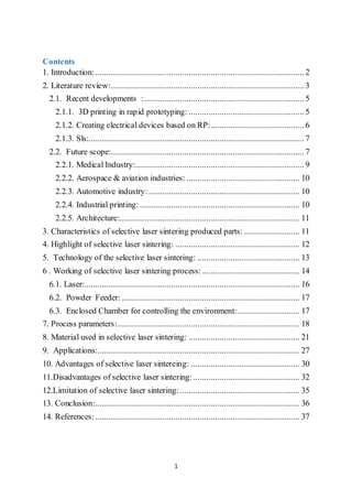
  • 14. 14 fully enclosed element. This is because the unsintered powder within the element can't be drained. Since patents have started to expire, affordable home printers have become possible, but the heating process is still an obstacle, with a power consumption of up to 5 kW and temperatures having to be controlled within 2 °C for the three Stages of preheating , melting and storing before removal. 6 . Working of selective lasersintering process: The term "sintering" refers to a process by which objects are created from powders using the mechanism of atomic diffusion. Although atomic diffusion occurs in any material above absolute zero, the process occurs much faster at higher temperatures which is why sintering involves heating a powder. Sintering is different from melting in that the materials never reach a liquid phase during the sintering process. It (SLS) is a powder-based layer-additive manufacturing process generally meant for rapid prototyping and rapid tooling. Laser beams either in continuous or pulse mode are used as a heat source for scanning and joining powders in predetermined sizes and shapes of layers. The geometry of the scanned layers corresponds to the various cross sections of the computer-aided design (CAD) models or (STL) files of the object. After the first layer is scanned, a second layer of loose powder is deposited over it, and the process is repeated from bottom to top until the part is complete.[16,20] In
  • 15. 15 this process a high power laser beam selectively melts and fuses powdered material spread on a layer. The powder is metered in precise amounts and is spread by a counter-rotating roller on the table. A laser beam is used to fuse the powder within the section boundary through a cross-hatching motion. The table is lowered through a distance corresponding to the layer thickness (usually 0.01 mm) before the roller spreads the next layer of powder on the previously built layer. The unsintered powder serves as the support for overhanging portions, if any in the subsequent layers .[25,26] Figure 1 . SLS system
  • 16. 16 Figure 2 . Laser sintering nomenclature 6.1. Laser: LASER is the main source to carry out the process which develops energy to sinter the powder particles. The energy source laser is either pulsed or continuous wave laser. Laser power along with the scanning speed is one of the important parameter in the laser sintering process as it affects the overall mechanical properties of the produced part for example hardness, strength, porosity. CO2 Laser, Fibre Laser or Nd YAG laser can be used. Now a days. Fibre lasers are becoming most popular due to their high power, excellent control, less maintenance and reliability. The power requirements will depend on the raw material, speed of scanning etc. R. M. Miranda used 8KW fibre laser to sinter titanium based alloy
  • 17. 17 6.2. Powder Feeder: SLS uses a powder feeder mechanism which lays a powder bed of a predetermined thickness over the base plate on which part is to be built. It is one of the essential component of any SLS based rapid prototyping machine. The layer of powder has to be very accurate and consistent over the complete process assuring the uniformity of the part throughout the geometry. Researchers have used various techniques to deposit a layer for their experiments such as roller arrangements, scrapper blades etc. There are some techniques like  Classical deposition  Pressure gradient deposition  Ultrasound deposition  Spread method 6.3. EnclosedChamberfor controlling the environment: SLS process involves diffusion of the atoms of one particle into atoms of adjacent particle. The heat energy involved is very high which will be near the melting point of the materials. At this high temperature, there are lot of chances of oxidation of surface which is in contactof the air. To controlthe oxidation, an inert gas atmosphere is provided. K.Murali used argon gas to drive out the air from reactive zone. Vacuum gives the additional mechanical stability to the part if provided.
  • 18. 18 7. Processparameters: Process parameters are the defined variables that influence and control the SLS process. A number of parameters can affect the quality of parts fabricated using SLS. The parameters that vary in SLS include powder size, scan speed, powder density, pulse frequency, fill laser power, scan size, scan spacing, part-bed temperature, layer thickness, pulse size, laser power, laser energy, spot size, powder size distribution, ratio of the powders of the mixture . Design of experiment is necessary to find the significant parameters and the effect of those parameters on the physical and mechanical characteristics of the parts. The amount of energy that can be maintained at the surface for a given point during the laser irradiation-materials interaction period is dependent on the period of single exposure, the number of total exposures, the time between each exposure and also the intensity of the laser irradiation . Some parameter are:[2,7] 7.1. Duration of a pulse : The duration of a pulse is a function of the laser beam spot size, D, and linear velocity, V, of the laser .The exposure period of the laser irradiation is defined as τ = D/V ... (1) where τ is the duration of a pulse.
  • 19. 19 7.2. Overlap : The number of the exposures seen by a point on a surface is related to the overlap, O. The function of overlap is described by the ratio of hatch spacing, HS, to spotsize, D, that O=1-D/HS ...(2) A single point on the powder surface is exposed to laser irradiation multiple times due to overlapping scan lines. Overlapping scanning patterns are achieved as the distance between scan lines, hatch spacing, is always less than the laser beam radius. 7.3. Number of exposures : The number of total exposures, Ne, is defined as Ne=D/HS-1 ..(3) The amount of energy stored at the sintered surface is determined on the time between exposures. Laser power, laser beam spot size, hatching spacing, laser beam speed (or step speed) and the scan line vector length are independent process parameters which govern the intensity and method of energy delivered to the powder surface. 7.4. Powder: Intensity of the laser irradiation is related to power and spot size by integrating the radial intensity of the spot area such that p= ∫ 𝐼 𝑅𝑏 0 (r). 2π r dr ..(4) where I(r) is the radial intensity distribution, r is the radial distance from the center of the spot and Rb is the spot radius.
  • 20. 20 7.5. Dwellperiod : During the SLS process, energy is lost due to conduction into the powder bed and radiation and convection at the surface during the dwell period. The delay period between successive irradiation exposures is determined by the linear velocity, V, of the laser beam and also the scan line length, L. The delay period, td, is defined as td=L/V ..(5) The energy stored at the surface during the SLS process is determined by considering the intensity of laser radiation, number of exposures, the length of each exposure and the delay between successive exposures.
  • 21. 21 8. Materialused in selective lasersintering: The SLS process flexibility allows a variety of materials. Some of these materials make the SLS process superior to other rapid prototyping techniques, where the material properties depend on the process. Among these materials, the most common are: wax, paraffin, polymer-metal powders, or various types of alloys, polymers, nylon and carbonates. Polycarbonate powders were initially used as starting materials for both experimentation and modelling in the SLS process. For example, a number of systems and metal alloys (Fe-Cu, Fe-Sn, Cu-Sn), metals (Al, Cr, Ti, Fe, Cu), ceramics (Al2O3, FeO, NiO, ZrO2, SiO2, CuO) and other alloys (bronze, nickel, Inconel 625) were tested for laser sintering. The results demonstrated that any material could be combined with another material with a low melting point and acts as an adhesive. INCDMTM researchers tested the use of bonding a protective polymer, commonly used in conventional SLS sintering, thus revealing that a wide range of laser sintered materials can be bonded without protection, which is an advantage compared with other rapid prototyping techniques[20]. It appears that the use of special materials for rapid prototyping is growing and the quality of products is visibly higher. The sintering achieves higher performance if you use a powder mixture consisting of two groups of materials: (i)Thermoplastic materials (nylon, polyesters, waxes, some nylon or polycarbonate mixtures especially). (ii)Completion materials whose mechanical properties and thermal properties determined decisive use of new products (metal, non-metallic and composite).
  • 22. 22 With such networks, some remarkable performances have been achieved. (a) Some sustainable forms made from a special polycarbonate or a polyamide completing ceramics are used frequently (currently, fine casting workshops of metal parts in serial production conditions). (b) The direct implementation of successive layers of metallic parts in the future lead to a replacement casting processes for a satisfactory performance in terms of materials such as:  Copperalloy  Titanium alloys,  Toolsteel  Fire-resistant steel. They were made by selective sintering that takes place in a controlled atmosphere, a melting temperature, but their cost is very high and, for the time, it is not being implemented in the industry. After , a great success and achievement is the metal part made from different metals in better economic conditions:  Ambient temperature  No protective atmosphere. Laser sintering powders used may have different components depending on the purpose for which the final product will be used. For example we show some
  • 23. 23 basic features and processes that occur when working with DM20 (DirectMetal 20) Powder for EOSINT M270 from EOS GmbH - Electro Optical Systems Germany. Photo ME, Co-Cr powder mixtures are shown in figure. figure 3. Co-Cr powdermixtures . Sampling batches purity and their repeatability are paramount conditions closely followed by manufacturers of metal powder mixtures recipes of biocompatible metallic powders, any abnormality leading to product rejection (both in terms of physics, mechanics and biomedicine). The particle size diagram is shown in figure .
  • 24. 24 Figure 4 : particle size diagram The procedures of selective sintering (SLS – Selective Laser Sintering) developed after 1992 are based on the experience gained in designing and manufacturing stereo lithography equipment (STL) and the expansion of technological research on other groups of materials with mechanical properties closer to the technological needs of functional assemblies engineering (ceramics, ferrous and nonferrous metals). In this way, we managed to demonstrate that a thin layer of certain mixtures of powders under the action of the laser beam can reach the local level, function and duration of exposure, which marks the transition of the melting temperature of the powder layer in the liquid.[15] Based on the physical properties of the powders used, immediately after the laser beam action ceases, the local solidification takes place, achieving a compact drawstring made after the directions of molecular chains, surrounded by a volume of powders unexposed to the beams mentioned above. A view with emphasis on individual layers of the solidified powder bed is shown in figure .
  • 25. 25 figure 5. individual layers of the solidified powder. The explanation is more complex because the solidification range of materials is especially diverse. It is essentially based on stereo lithography processes exposed to the same mechanism: the installation of chemical bonds that form macromolecular linear chains, or three-dimensional tree. For these situations state transitions, which involve a significant local heat input, they can be accelerated by inhibiting initialized and controlled substances, and energy intake may be given by concentrated heat sources on the desktop, laser radiation etc. Micrographic appearance of pure metal powder is shown in figure 6.These sources must be adapted and adjusted on the fly, so as to give extra heat necessary to achieve the melting temperature, which provides thermo-kinetic conditions favorable for the development process by establishing the macromolecular chains and a partially crystalline structure, with the transition
  • 26. 26 of the liquid state to the solid state, reinforced, which marks the sintering product. figure 6. Micrographic appearance of pure metal powder. In terms of energy, the powders used in the in powdery have a wide range of melting temperatures which require a different input of heat from the concentrated source of energy. Choosing the necessary activation energy is possible by selecting rapid heating schemes in accordance with the dynamics of the sintering process. The diversity of these schemes has attracted a final designation of laser sintering. In conclusion, this phase is superior to the anterior period when the stereo lithographic technologies and equipments have been researched, designed and homologated. Selective laser sintering processes are based on a variety of materials which will result in superior products at a stage performance, is the physical and mechanical properties close to the loads of the usual parts of a machine. Rapid prototyping and manufacturing technologies using materials and processes have been developed in recent years in several directions, depending on the material used and the technology of solidification of the material.[15]
  • 27. 27 9. Applications: SLS materials are suited for direct functional applications where robust performance characteristics are required. Chemical resistance to alkalines, hydro carbonates, fuels and solvents, High temperature applications, Wear and abrasion, Flexibility, thin walls, internal/external surface pressures.Applications in the various fields are:[21,25] (i) Rapid Manufacturing : Aerospace Hardware, Medical and Healthcare, Electronics, Packaging, Connectors, Homeland Security, Military Hardware Rapid Prototypes, Functional Proof of Concept Prototypes, Design Evaluation Models (Form, Fit & Function), Product Performance & Testing, Engineering Design Verification, Wind-Tunnel Test Models. (ii) Tooling and Patterns : Rapid Tooling, Injection Mould Inserts Tooling and Manufacturing Estimating Visual Aid, Investment Casting Patterns Jigs and Fixtures, Foundry Patterns, Sand Casting. (iii)Parts for mechanical and thermal tests: The polyamides material allows the production of strong, durable parts that can be used tor extensive functional testing. Sintered products have mechanical properties comparable to those of injection molded PA 12 parts, typical applications are snap fits but it is also possible to produce working hinges. Polyamide parts with glass filling have a much higher thermal resistance and are perfectly suited for lighting elements and ventilation systems or products that require high thermal loads. Apart from their use as test products, the
  • 28. 28 functional SLS parts often also need to be used at the same time for a visual/csthetical control or dimensional check. (iv)Series of small plastic parts: SLS is an interesting and cost-effective alternative to injection molding (Rapid Tooling). With the P 700 machine which has a large build area, a series of small pieces can be built in one single laser sintering process. This dramatically decreases the price, as the cost of an SLS part depends on its volume. Or in other words, the cost is defined by the amount of powder it takes to build it and not by an initial investment in an injection molding tool. Moreover, series of SLS parts are available in a few days. So no need for high start-up investments, no long lead times to produce a mould and injection mould the parts, no difficulties in case the parts are complex. Figure 7.sls fabricated part (v)Large and complex functional parts: The machines can build large, complex geometries in one piece( shown in figure), up to 700x380x580mm. The number of layers to be built is significantly
  • 29. 29 reduced as large parts can be built horizontally, which considerably shortens the building process. Parts exceeding the P 700' maximum dimensions .can be built in multiple pieces and put together afterwards. The process of gluing sub-parts and assembling components can be done in the most accurate and secure way using the Rapid Fit system. Rapid Fit allows to firmly position the parts on a unique support system with individualized fixtures, supporting the part on well positioned points. (vi) Agricultural applications : Since the introduction of plastic films in the 1930s and 1940s for greenhouse coverings, fumigation and mulching, agricultural applications of polymers have grown at an enormous rate. All classes of polymers such as plastics, coatings, elastomers, fibres and water-soluble polymers utilize the applications with the control release of pesticides and nutrients, soil conditioning, seed coatings, gel plantings and plant protection. Biodegradable polymers could also be used in the field of agriculture as soil-improving materials[9].
  • 30. 30 10. Advantages of selective laser sintereing: This research was mainly focused on the SLS process as it offers the widest range of materials compared to any other RP systems. SLS is capable of handling a range of materials such as polycarbonate, nylon, fine nylon, medical grade fine nylon, glass-filled nylon, sand, rapid steel, copper, polyamide and formulations called trueform, veriform, protoform and duraform. There are already attempts to use new and untested materials to fabricate objects . The primary advantage of SLS is the flexibility of selection of material systems compared to other Solid Freedom Fabrication techniques . SLS is also ideal for applications that require functional properties. Specific attributes of SLS include investment casting, multiple materials (to meet a variety of applications requirements) and durable materials (especially composite and fine nylon for functional prototyping applications). Another advantage of SLS is its close relationship with three dimensional computer-aided design modeling systems. In fact, regard it as a general prerequisite in any process. SLS also provides for an ideal inert sterilized environment for the building of drug delivery devices which is one of the applications of the manufacture of functionally graded materials. This is mainly due to its enclosed build chamber, the build materials that come in a dry powder medium and the nitrogen gas-permeated heated chamber. These features can be exploited to prevent the growth of bacteria when building drug delivery devices. Complex prototypes can be created by SLS in the design phase or for generating small quantities of production parts. It is also an ideal technology for the iterative design process. SLS process is so effective that it can prototype many more parts compared that can be done by traditional methods. Since no tooling is required, most of the patterns can be created and ready for casting within 24 hours. Multiple patterns can be created in a single build which allows
  • 31. 31 for multiple iterations of the same part for testing or different parts for multiple designers and teams within a company. As a result, more parts can be created by using SLS compared with the traditional methods. The amount of money and time saved by using SLS to create patterns is enormous. The SLS process is powder based which means that there are no support structures to create during the process or to remove afterwards. And this would improve build rates, minimize pre-processing and post-processing labor and also create distinct advantage over many other rapid prototyping processes. Parts also can be nested inside one another and stacked vertically in the build chamber for maximum productivity.[13] SLS also provides itself an ability to turn patterns around quickly. Jobs with sample patterns and parts in hand can be quoted. Design changes and modifications can be easily accommodated once a job has been started. This would give SLS users a very competitive advantage.
  • 32. 32 11.Disadvantagesofselective lasersintering: Common problems such as bonus z, clumping, curling, growth, cracking of powder bed, etc occur during the selective laser sintering. Some of them are due to inappropriate settings, handling, processing or maintenance of the Sinterstation system. This would result in prototypes of poor quality. Sometimes, serious damages are introduced to the components. The details of the problems would be described as follows . (i)Bonus z : is the growth of a part in a downward z direction. This occurs when the laser beam penetrates through to the unsintered powder below the part boundary during the scanning stage of the first layer. As a result, the growth of the part in the z-direction occurred. And this would cause out of tolerance of the part .[22] No table of figures entries found.Figure 1 Figure 8. Schematic diagram of bonus z in the SLS process
  • 33. 33 (ii) Clumping : Also occurs in the SLS process. It refers to agglomerated powder in front of the roller on the powder surface. The roller pushes clumps across the part bed and it may cause streaks to appear after the rolling process. Clumping is caused by improperly sifted and recycled powder and also overheating of the powder in the feed cartridges. Clumping would result in part of poor quality as powder cannot be fed properly. It also causes some side effects due to improper powder feeding such as uneven powder thickness, which may cause growth or inadequate melting. Streaks may be apparent on upward and downward facing surfaces of parts. Figure 9.Schematic diagram of clumping in the SLS process (iii)Curling (or in-build): is the rise of edges or corners of the part above the powder bed surface after a layer of powder is scanned by the laser beam. This would make the parts thinner in the z-axis and not flat in shape as designed. The temperature differences that exist between various regions of the part during the selective laser sintering process is one of the reasons which causes the problems. These temperature differences cause uneven shrinkage and thus curing is resulted. In-build curl usually occurs when the part temperature dips
  • 34. 34 too low after a layer of powder is added. In-build curl can also occur when the part bed temperature is too low .[22] Figure 10. Schematic diagram of curling (or built in) in the SLS process (iv)Growth: Growth occurs when the detailed features of the part blur. It is particularly apparent with small features or small holes. This would result in part of oversize and increase the difficulty in breakout of the part. The main difference between growth and bonus z is that growth may occur on any part edge while bonus z occurs only on downward facing surfaces .[22] Figure 11. Schematic diagram of growth
  • 35. 35 (v)Cracking : of powder bed also occurs in the SLS process when the roller moves across it. This is caused by excessive heating rate or temperature from the heaters, which causes partial melting of the powder bed surface. Cracking also causes other problems like clumping and streaking . Figure.12 Schematic diagram of cracking of part bed 12.Limitation of selective lasersintering: (i). Surface finish: The surface of an SLS part is powdery, like the base material whose particles are fused together without complete Melting. The smoother surface of an SLA part typically wins over SLS. (ii). Dimensional accuracy: SLA is more accurate immediately after completion of the model, but SLS is prone to residual stresses that are caused by long term curing and environmental stresses. Both SLS and SLA suiler from inaccuracy, but SLS is less predictable because of the variety of materials and process parameters[1].
  • 36. 36 13. Conclusion: Over the last decade Rapid Prototyping techniques gained a wide acceptance. Among the different RP techniques, Selective Laser Sintering had the advantage of being able to process a wide range of materials. This large variety of materials gradually allowed to extend the field of applications, from simple visual prototyping to functional prototyping, and even Rapid Tooling and Rapid Manufacturing applications. In recent years, the idea of full melting metal powders was explored, supported by the continuously improving process parameters (smaller layer thickness, smaller spot size, etc.), resulting in mechanical properties being much better than those of early time selective laser sintered parts and comparable with bulk metal properties. Rapid Tooling and specially Rapid Manufacturing technologies are still limited in use, but they are steadily growing. It can be expected that in the next decade they will achieve the same level of acceptance as Rapid Prototyping, by continuous improvement of material properties and accuracy and by a decrease of the costs. Itcan be concluded that, among various techniques of rapid prototyping Selective Laser Sintering is the most flexible process that accommodates large variety of materials being processed. Though the technique used is difficult to control and automate as the large number of parameters included, having its superior qualities, it is the most important and useful process for various industrial applications.
  • 37. 37 14. References: [1] Read N, Wang W, Essa K, Attallah MA.(2015) ,Selective laser melting of AlSi10Mg alloy: process optimisation and mechanical properties development. Mater Des 2015;65:417–24. [2] T. Pereira, et al., (2012) , Effect of process parameters on the properties of selective lasersintered poly (3-hydroxybutyrate) scaffolds for bone tissue engineering: this analyzes how laser scan spacing and powder layer thickness affect the morphology and mechanical properties of SLS-made scaffolds by using a volume energy density function, Virtual Phys. Prototyp. 7 (4) (2012) 275–285. [3] Lou, Alex and Grosvenor, (December 07, 2012. Retrieved on March 22, 2013) Carol "Selective Laser Sintering, Birth of an Industry ", The University of Texas . [4] S. Singh, A. Sachdeva, and V. S. Sharma,(2012), Investigation of Dimensional Accuracy/Mechanical Properties of Part Produced by Selective Laser Sintering, International Journal of Applied Science and Engineering . [5] Olakanmi EO, Cochrane RF, Dalgarno KW.(2011) Densification mechanism and microstructural evolution in selective laser sintering of Al–12Si Powders. J Mater Process Technol ;211:113–21 [6] D. V, Gheorghe, (2011) Study of selective laser sintering –A qualitative and objective approach, The Scientific Bulletin of VALAHIA University – MATERIALS and MECHANICS – Nr. 6 (year 9). [7] D. Gu, Y Shen,(2011), Balling phenomena in direct laser sintering of stainless steel powder: Metallurgical mechanisms and control methods, Materials and Design 30 ,2903–2910.
  • 38. 38 [8] D. Gu, Y. Shen,(2008), Processing conditions and microstructural features of porous 316L stainless steel components by DMLS, Applied Surface Science 255 , 1880–1887 [9] N. Tukuru, et al., (2008),Rapid prototype technique in medical field, Res. J. Pharm. Technol.341–344 [10] R.M. Miranda, G. Lopes, L. Quintino, J.P. Rodrigues, S. Williams,(2008), Rapid prototyping with high power fiber lasers, Materials and Design . [11] C.C. Wang, T.W. Lin, S.S. Hu,(2007) Rapid prototyping Journal, 13/5, 304-315 [12] J. Kim, T.S. Creasy,Mater. (2004) Characterstics of selective laser sintering. 23 629-636 [13] V. K. Singh and N.S. Chauhan, (2004),An overview of rapid prototyping technology, IJAET International Journal of Application of Engineering and Technology, vol-2 no.-3, ISSN: 2395-3594. [14] S. Kumar, (2003). Selective laser sintering: a qualitative and objective approach. [15] J.P. Kruth, X. Wang, T. Laoui, L. Froyen,(2003) Lasers and materials in Selective Laser Sintering, The International Journal of Assembly Technology and Management, vol. 23-4, [16] K. Murali, A.N. Chatterjee, P. Saha, R. Palai, S. Kumar, S.K. Roy, P.K. Mishra, A. Roy Choudhury, (2003),Direct selective laser sintering of iron– graphite powder mixture, Journal of Materials Processing Technology 136 [17] S. Kumar, (2003). Selective laser sintering: a qualitative and objective approach. JOM, 55(10), 43-47. [18] H.C.H. Ho, W.L. Cheung, I. Gibson, (2002)Rapid Prototyping 8 , 233–242.
  • 39. 39 [19]. C.M. Cheah et al.( 2002), “Rapid Sheet Metal Manufacturing, Part 2: Direct Rapid Tooling”, International Journal of Advanced Manufacturing Technology, 19 , pp. 510 [20]. J.P. Kruth et al. (2001), “Lasers and Materials in Selective Laser Sintering”-Proceeding of 3rd Laser Assisted Nearshape Engineering Conference (LANE-2001), Erlangen, Germany: Lehrstuhl fur Fertigungstechnologie, , pp. 3–24. [21] Pham, D.T. and Dimov, S.S. (2001), Rapid Manufacturing: The Technologies and Applications of Rapid Prototyping and Rapid Tooling, Springer,London. [22]Wohlers,1997,Lee, 1999, Cooper, 2001 and DTM Corporation. [24] J.D. Williams, C.R. Deckard,( 1998),Rapid Prototyping Journal, 4 , 90-100. [25] P.M. Pandey,( 1991),Rapid prototyping technologies, applications and Part deposition planning. [26] J.P.Kruth (1991) Material Incress Manufacturing by Rapid Prototyping Technologies, CIRP Annals, Vol. 40, 2, pp 603-614. [27] J.P.Kruth (1991) Material Incress Manufacturing by Rapid Prototyping Technologies, CIRP Annals, Vol. 40, 2, pp 603-614.