SlideShare uma empresa Scribd logo
1 de 14
Baixar para ler offline
Problem:
Make a comparative study and performance analysis of different modulation
techniques which shows graphically and comparative results like Bandwidth,
Energy and Power Efficiency of AM, DSB-SC, SSB and SSB-SC.
Write a report on your analysis and justification of your results.
Abstract:
Several studies have been dedicated to the analysis of different modulation techniques. This paper
details a performance analysis of various modulation techniques like AM, DSB-SC, SSB, SSB-SC.
The aim of this study is to analyse and compare various techniques based on various parameters such
as bandwidth, power, energy, efficiency etc. AM generation involves mixing of a carrier and an
information signal. In Low level modulation, the message signal and carrier signal are modulated at
low power levels and then amplified. The advantage of this technique is small is that a small audio
amplifier is sufficient to amplify the message signal.
Keywords:
Modulation, Power, Efficiency, Bandwidth, Amplitude Modulation (AM), Double Sideband
Suppressed Carrier (DSB-SC), Single Sideband Suppressed Carrier (SSB-SC), Single Sideband SSB.
Introduction:
Communication is the process of conveying message or exchanging information. It means that
transmission of the encoded symbols transmitted in the communication channel, at the receiver
information is decoded and which recreates the original data. A message carrying a signal has to get
transmitted over a distance and for it to establish a reliable communication, it needs to take the help of
a high frequency signal which should not affect the original characteristics of the message signal.
Fig 1: Layout of Basic Analog Communication System
Modulation technique is used in communication process which increases the range of communication,
multiplexing and improves quality of reception. It is defined as the process of superimposing the
information contents of a base band signal on a carrier signal (which is of high frequency) by varying
the characteristic of carrier signal according to the message signal.
Advantages of implementing modulation in communication system are:
 Reduction of antenna size
 Increased in communication range
 Possibility of bandwidth adjustment.
 Improved reception quality
The types of modulations are broadly classified into continuous-wave modulation and pulse modulation.
In continuous-wave modulation, a high frequency sine wave is used as a carrier wave. This is further
divided into amplitude and angle modulation. If the amplitude of the high frequency carrier wave is
varied in accordance with the instantaneous amplitude of the modulating signal, then such a technique
is called as Amplitude Modulation. If the angle of the carrier wave is varied, in accordance with the
instantaneous value of the modulating signal, then such a technique is called as Angle Modulation.
Angle modulation is further divided into frequency modulation and phase modulation. If the frequency
of the carrier wave is varied, in accordance with the instantaneous value of the modulating signal, then
such a technique is called as Frequency Modulation. If the phase of the high frequency carrier wave is
varied in accordance with the instantaneous value of the modulating signal, then such a technique is
called as Phase Modulation.
Fig 2: Types of Modulation in Analog Communication System
As we discussed earlier modulation is a very important process in communication systems,
because the voice signal is dynamically varying signal hence need a high speed DSP processor to
process the signals accurately .The modulation schemes are broadly classified into two categories such
as analog and digital modulations .The topic for implementation is Amplitude modulation followed by
Double Sideband Suppressed Carrier (DSB-SC), Single Sideband (SSB) and Single Sideband
Suppressed Carrier (SSB-SC).
Methodology:
Amplitude Modulation:
According to the standard definition, “The amplitude of the carrier signal varies in accordance with the
instantaneous amplitude of the modulating signal” Which means, the amplitude of the carrier signal
containing no information varies as per the amplitude of the signal containing information, at each
instant. A continuous-wave goes on continuously without any intervals and it is the baseband message
signal, which contains the information. This wave has to be modulated. This can be well explained by
the following figures.
Fig 3: Baseband Signal Fig 4: Carrier Signal
Fig 5: Amplitude Modulated (AM) Signal
The first figure shows the modulating wave, which is the message signal. The next one is the carrier
wave, which is a high frequency signal and contains no information. While, the last one is the resultant
modulated wave. It can be observed that the positive and negative peaks of the carrier wave, are
interconnected with an imaginary line. This line helps recreating the exact shape of the modulating
signal. This imaginary line on the carrier wave is called as Envelope. It is the same as that of the
message signal.
Let the modulating signal be: m(t)=Am cos (2πfmt).
The carrier signal be: c(t)=Ac cos (2πfct).
The modulated wave be: s(t) = [Ac + Amcos (2πfmt)] cos (2πfct) s(t)………Eq. 1
Ac and Am are the amplitudes of carrier and message signal respectively.
fc and fm are frequency of carrier and message signal respectively.
Modulating Index:
A carrier wave, after being modulated, if the modulated level is calculated, then such an attempt is
called as Modulation Index or Modulation Depth. It states the level of modulation that a carrier wave
undergoes.
Rearranging the Eq. 1 as below:
s(t) = Ac [1 + (Am/Ac) cos (2πfmt)] cos (2πfct) s(t)
⇒ s(t )= Ac [1 + μ cos(2πfmt)] cos (2πfct) ………Eq. 2.
Where, μ is Modulation index and it is equal to the ratio of Am and Ac. Mathematically, we can write
it as: μ=Am/Ac.
Bandwidth of AM Wave:
It is the difference between the highest and lowest frequencies of the signal. Mathematically, we can
write it as: BW = fmax - fmin.
Consider the following equation of amplitude modulated wave:
s(t)=Ac [1 + μ cos (2πfmt)] cos (2πfct) s(t)
⇒ s(t) = Ac cos (2πfct) + Ac μ cos (2πfct) cos (2πfmt)
⇒ s(t) = Ac cos (2πfct) + Ac μ/2cos [2π (fc + fm) t] + Ac μ/2cos [2π(fc−fm) t]
Hence, the amplitude modulated wave has three frequencies. Those are carrier frequency fc, upper
sideband frequency (fc + fm) and lower sideband frequency (fc - fm).
BW = (fc + fm) − (fc - fm)
⇒BW=2fm
Power of AM Wave:
Consider the following equation of modulated wave:
s(t)=Ac cos (2πfct) + Ac μ/2cos [2π (fc + fm) t] + Ac μ/2 cos [2π (fc − fm) t]
Power of AM wave is equal to the sum of powers of carrier, upper sideband, and lower sideband
frequency components: Pt=Pc + PUSB + PLSB
We know that the standard formula for power of cos signal is: P=vrms
2
/R=(vm/√2)2
/2
Pc=(Ac/2√2)2
/R=AC
2
/2R
PUSB = (Ac μ/2√2)2
/R=Ac
2
μ2
/8R
PLSB = Ac
2
μ2
/8R.
Pt = AC
2
/2R+ Ac
2
μ2
/8R+ Ac
2
μ2
/8R=(Ac2
/2R) (1+μ2/4+μ2/4).
Pt = Pc (1+μ2/2)
Double Sideband Suppressed Carrier (DSBSC):
In the process of Amplitude Modulation, the modulated wave consists of the carrier wave and two
sidebands. The modulated wave has the information only in the sidebands. Sideband is nothing but a
band of frequencies, containing power, which are the lower and higher frequencies of the carrier
frequency. The transmission signals contain a carrier with two sidebands (known as Double Sideband
Full Carrier) as shown below:
Fig 6: Sidebands of Carrier Signal
However, such a transmission is inefficient. Because, two-thirds of the power is being wasted in the
carrier, which carries no information. If this carrier is suppressed and the saved power is distributed to
the two sidebands, then such a process is called as Double Sideband Suppressed Carrier system or
simply DSB-SC. It is plotted as shown in the following figure:
Fig 7: Suppressed Carrier Signal
Let the modulating signal be: m(t)=Am cos (2πfmt)
The Carrier Signal be: c(t) = Ac cos (2πfct)
Equation for DSB-SC modulated wave: s(t)=m(t)c(t)
⇒ s(t) = Am Ac cos (2πfmt) cos (2πfct)
Bandwidth of DSBSC Wave:
Bandwidth (BW): BW = fmax − fmin
Equation for DSB-SC modulated wave:
⇒ s(t) = Am Ac cos (2πfmt) cos (2πfct)
⇒ s(t) = Am Ac/2 cos [2π (fc + fm) t] + Am Ac/2cos [2π (fc−fm) t]
The DSBSC modulated wave has only two frequencies. So, the maximum and minimum frequencies
are (fc + fm) and (fc − fm) respectively.
fmax = (fc + fm) and fmin = (fc−fm)
BW = (fc + fm) − (fc−fm)
⇒ BW = 2fm.
Power of DSBSC Wave:
Equation for DSB-SC modulated wave:
s(t) = Am Ac/2cos [2π (fc + fm) t] + Am Ac/2cos [2π (fc−fm) t]
Power of DSBSC wave is equal to the sum of powers of upper sideband and lower sideband frequency
components.
Pt = PUSB + PLSB
P = vrms
2
/R=(vm√2)2
/R
PUSB = (Am Ac/2√2)2/R = Am
2
Ac
2
/8R
Similarly, we will get the lower sideband same power as that of upper sideband:
PLSB = Am
2
Ac
2
/8R
Now, let these two sideband powers are added in order to get the power of DSBSC wave:
Pt = Am
2
Ac
2
/8R+ Am
2
Ac
2
/8R
⇒ Pt = Am
2
Ac
2
/4R
Single Sideband Modulation (SSB):
The single-sideband modulation definition is a modulation which is used for transmitting information
like an audio signal through radio waves. This modulation is used in radio communications by using
transmitter power & more bandwidth efficiently for an alteration of AM (Amplitude Modulation).
There are many radio communication devices available in the market which use single sideband radio
like SSB Tx, SSB Rx, and SSB transceiver.
There are several variations are used for SSB modulation like lower sideband (LSB), upper sideband
(USB), double sideband (DSB), Single Sideband Suppressed Carrier (SSB SC), Vestigial Sideband
(VSB), and SSB reduced carrier.
Fig 8: Single Sideband Modulation (SSB)
Power of SSB Wave:
It is often necessary to define the output power of a single sideband transmitter or single sideband
transmission. Power measurement for an SSB signal is not as easy as it is for many other types of
transmission because the actual output power is dependent upon the level of the modulating signal. To
overcome this a measure known as the peak envelope power (PEP) is used. This takes the power of the
RF envelope of the transmission and uses the peak level of the signal at any instant and it includes any
components that may be present. Obviously, this includes the sideband being used, but it also includes
any residual carrier that may be transmitted. The level of the peak envelope power may be stated in
Watts, or figures quoted in dBW or dBm may be used. These are simply the power levels relative to 1
Watt or 1 milliwatt respectively.
Single Sideband Suppressed Carrier (SSBSC):
The DSBSC modulated signal has two sidebands. Since, the two sidebands carry the same information,
there is no need to transmit both sidebands. We can eliminate one sideband. The process of suppressing
one of the sidebands along with the carrier and transmitting a single sideband is called as Single
Sideband Suppressed Carrier system or simply SSBSC.
It is plotted as shown below:
Fig 9: Single Sideband Suppressed Carrier (SSBSC)
In the above figure, the carrier and the lower sideband are suppressed. Hence, the upper sideband is
used for transmission. Similarly, we can suppress the carrier and the upper sideband while transmitting
the lower sideband. This SSBSC system, which transmits a single sideband has high power, as the
power allotted for both the carrier and the other sideband is utilized in transmitting this Single
Sideband.
Let the modulating signal be: m(t) = Am cos (2πfmt)
The Carrier Signal be: c(t)=Ac cos (2πfct)
The equation for SSBSC is:
s(t) = Am Ac/2 cos [2π (fm + fm) t]; for the upper sideband
s(t) = Am Ac/2 cos [2π (f c− fm) t] s(t); for the lower sideband
Bandwidth of SSBSC Wave:
Since the SSBSC modulated wave contains only one sideband, its bandwidth is half of the bandwidth
of DSBSC modulated wave. i.e., Bandwidth of SSBSC modulated wave = 2fm/2 = fm
Therefore, the bandwidth of SSBSC modulated wave is fm and it is equal to the frequency of the
modulating signal.
Power of SSBSC Wave:
Let the SSBSC modulated wave be:
s(t) = Am Ac/2 cos [2π (fm + fm) t]; for the upper sideband
s(t) = Am Ac/2 cos [2π (f c− fm) t] s(t); for the lower sideband
Power of SSBSC wave is equal to the power of any one sideband frequency components.
Pt = PUSB = PLSB
The power of the upper sideband is: PUSB = (Am Ac/2√2)2
/R = Am
2
Ac
2
/8R
The power of the lower sideband is: PLSB = Am
2
Ac
2
/8R
Code for Output Waveforms of AM, DSBSC, SSB, SSBSC:
Amplitude Modulation (AM):
m = input(‘Modulation index = ‘);
t = linespace(0,0.2,1000);
Am = 5; % amplitude of message signal
fm = 10; % frequency of message signal
M = Am*cos(2*pi*fm*t); % message signal
figure;
subplot(4,1,1);
plot(t,M);
title(‘Message Signal’);
xlabel(‘time(t)’);
ylabel(‘Amplitude’);
%% Carrier Signal :
Ac = Am/m; % amplitude of carrier signal
fc = 20; % frequency of carrier signal
C = Ac*cos(2*pi*fc*t); % carrier signal
subplot(4,1,2);
plot(t, C);
title(‘Carrier Signal’);
xlabel(‘time(t)’);
ylabel(‘Amplitude’);
y = ammod(M, fc, 100, 0, Ac); % modulated signal
% ammod(M,fc,fs,INI_PHASE,CARRAMP)
subplot(4,1,3),plot(t, y);
title(‘Modulated Signal’);
xlabel(‘time(t)’);
ylabel(‘Amplitude’);
ylim([-20, 20]);
Double Sideband Suppressed Carrier (DSBSC):
function amplitude = dsbsc
fm = input(‘Enter the value of message signal frequency:’);
fc = input(‘Enter the value of carrier signal frequency: ‘);
Am = input(‘Enter the value of message signal amplitude:’);
Ac = input(‘Enter the value of carrier signal amplitude:’);
Tm = 1/fm;
Tc = 1/fc;
t1 = 0:Tm/999:6*Tm;
message_signal = Am*sin(2*pi*fm*t1);
subplot(3,1,1)
plot(t1, message_signal, ‘r’);
grid();
title(‘Message signal’);
carrier_signal = Ac*sin(2*pi*fc*t1);
subplot(3,1,2)
plot(t1, carrier_signal,’b’ );
grid();
title(‘Carrier Signal’);
amplitude = message_signal.*carrier_signal;
subplot(3,1,3)
plot(t1,amplitude,’g);
grid();
title(‘DSBSC’);
end
Single Sideband Modulation (SSB):
function SSBAM
td = input(‘n Enter the total Signal Durationnn ->’);
ts = input(‘n Enter the sampling time for this signal and it should be less than
1nn ->’);
fc = input(‘ n Enter the carrier frequency of the cosine wave nn ->’);
k = input(‘n Enter the constant diminishing factor nn->’ );
%fs = 1/ts ;
t = 0:ts:td;
t2 = int64( (t/ts) +1 );
m(t2) = input(‘ n Enter the msg signal as a function of time “t”; nn ->’);
w(t2) = hilbert(m(t2));
c = cos((2*pi*fc*t));
cp = sin((2*pi*fc*t));
s(t2) = (c.*(1+k*m(t2))+cp.*(1+k*w(t2)));
u(t2) = (1+k*m(t2)).*c;
subplot(2,1,1),plot(t,s(t2));
grid minor
title(‘Single SideBand Modulation’)
subplot(2,1,2),plot(t,u(t2));
title(‘DSB Signal’)
grid minor
d = input(‘ n IF FUNCTION OF FOURIER TRANSFORM IS NEEDED PRESS “1” nn ->’);
if d==1
syms t;
M = input(‘ n REENTER THE MESSAGE SIGNAL AS A FUNCTION OF TIME BUT FOR THE
INFINITE TIME PERIODnn ->’);
U = (1+k*M)*(1/2)*(cos(2*pi*fc*t) + abs(cos(2*pi*fc*t)));
FourierTransform = fourier(U)
end
Single Sideband Suppressed Carrier (SSBSC):
function am = ssbsc
Am = input(‘Enter the value of message signal Amplitude:’);
Ac = input(‘Enter the value of carrier signal Amplitude:’);
fm = input(‘Enter the value of message signal frequency:’);
fc = input(‘Enter the value of carrier signal frequency:’);
m = Am/Ac;
A = (m*Ac);
Tm = 1/fm;
Tc = 1/fc;
t = 0:Tm/999:6*Tm;
message_signal = Am*sin(2*pi*fm*t);
carrier_signal = Ac*sin(2*pi*fc*t);
x1 = cos(2*pi*fc*t).*cos(2*pi*fm*t);
x2 = sin(2*pi*fc*t).*sin(2*pi*fm*t);
x3 = x1+x2;
x4 = x1-x2;
SSBSC_lsb = A*(x3);
SSBSC_usb = A*(x4);
subplot(4,1,1)
plot(t, message_signal, ‘r’);
grid();
title(‘message signal’);
subplot(4,1,2)
plot(t, carrier_signal , ’g’);
grid();
title(‘Carrier signal’);
subplot(4,1,3)
plot(t, SSBSC_lsb,’b’);
grid();
title(‘LSB of SSBSC wave cutting off USB’);
subplot(4,1,4)
plot(t, SSBSC_usb, ‘r’);
grid();
title(‘USB of SSBSC wave cutting off LSB’);
end
Results:
The basic research work carried out in the field of communication lead to the development of new
modulation techniques, error performances analysis, having immunity to noise but the ever-increasing
demand of the faster communication system with large bandwidth requirements and transmitted power
has again generated a new requirement towards the development of newer techniques.
The comparison table for various parameters for AM, DSBSC, SSB, and SSBSC is shown below:
Parameters AM DSBSC SSB SSBSC
Variable
Characteristics
Amplitude Amplitude Amplitude Amplitude
Sideband
Suppression
No No
One Sideband
Completely
One Sideband
Completely
Carrier
Suppression
No Complete
Any One
Sideband
Complete
Modulating
Input
1 1 1 1
Bandwidth 2fm 2fm fm fm
Transmission
Efficiency
Low Moderate Maximum Maximum
Power High Medium Low Low
Complexity Simple Simple Complex Highly Complex
Performance
in presence of
noise
Low Average Average
Merits Easy detection
Low power
consumption,
simple
modulation
system
Bandwidth
efficiency,
reduction in
distortion
Low power
consumption,
Better frequency
use
Demerits
Poor reception
quality,
Complex
detection
Complex
detection
Complex
detection
Table 1: Comparison of various parameters of AM, DSBSC, SSB and SSBSC
Conclusion:
An analysis of the modulation techniques carried out in this article reveals that the selection of a analog
modulation technique is solely dependent on the type of application. This is because of the fact that
some of the technique provide lesser complexities in the design of the modulation and demodulation
system and prove to be economic. Single sideband modulation, (SSB) is the main modulation format
used for analogue voice transmission for two-way radio communication on the HF portion of the radio
spectrum. Its efficiency in terms of spectrum and power when compared to other modes means that for
many years it has been the most effective option to use. Now some forms of digital voice transmission
are being used, but it is unlikely that single sideband will be ousted for many years as the main format
used on these bands.
References:
1) Lathi, B.P., “Modern Digital and Analog Communication,” Oxford University Press, New York,
1998.
2) ANALOG AND DIGITAL COMMUNICATION LABORATORY by Prof Shaik Aqeel,
Electronics and Telecommunication Engineering, Sreyas Institute of Engineering and Technology,
February 24, 2021.
3) John G. Proakis and Masoud Salehi, “communication systems engineering”, 2nd Ed, prentice hall,
2001.
4) Chapter 5, Traditional Analog Modulation Techniques, Mikael Olofsson, 2002-2007.
5) K. Sharma, A. Mishra & Rajiv Saxena, „Analog & Digital Modulation Techniques: An overview‟,
international Journal of Computing Science and Communication Technologies, VOL. 3, NO. 1, July
2010.
6) Schwartz, M.: Information Transmission, Modulation and Noise, McGraw-Hill, New York, 1990.

Mais conteúdo relacionado

Mais procurados

Introduction of digital communication
Introduction of digital communicationIntroduction of digital communication
Introduction of digital communication
asodariyabhavesh
 
Pulse amplitude modulation & demodulation
Pulse amplitude modulation & demodulationPulse amplitude modulation & demodulation
Pulse amplitude modulation & demodulation
Vishal kakade
 

Mais procurados (20)

Vestigial side band (vsb)
Vestigial side band (vsb)Vestigial side band (vsb)
Vestigial side band (vsb)
 
Am transmitter
Am transmitterAm transmitter
Am transmitter
 
Amplitude shift keying (ask)
Amplitude shift keying (ask)Amplitude shift keying (ask)
Amplitude shift keying (ask)
 
Delta modulation
Delta modulationDelta modulation
Delta modulation
 
Differential amplifier
Differential amplifierDifferential amplifier
Differential amplifier
 
signal and channel bandwidth
signal and channel bandwidthsignal and channel bandwidth
signal and channel bandwidth
 
Amplitude modulation
Amplitude modulationAmplitude modulation
Amplitude modulation
 
Delta Modulation
Delta ModulationDelta Modulation
Delta Modulation
 
Frequency Modulation and Demodulation
Frequency  Modulation and DemodulationFrequency  Modulation and Demodulation
Frequency Modulation and Demodulation
 
Pulse modulation
Pulse modulationPulse modulation
Pulse modulation
 
Pulse modulation, Pulse Amplitude (PAM), Pulse Width (PWM/PLM/PDM), Pulse Pos...
Pulse modulation, Pulse Amplitude (PAM), Pulse Width (PWM/PLM/PDM), Pulse Pos...Pulse modulation, Pulse Amplitude (PAM), Pulse Width (PWM/PLM/PDM), Pulse Pos...
Pulse modulation, Pulse Amplitude (PAM), Pulse Width (PWM/PLM/PDM), Pulse Pos...
 
Introduction of digital communication
Introduction of digital communicationIntroduction of digital communication
Introduction of digital communication
 
Pulse Code Modulation
Pulse Code ModulationPulse Code Modulation
Pulse Code Modulation
 
Amplitute modulation
Amplitute modulationAmplitute modulation
Amplitute modulation
 
Chapter 5
Chapter 5Chapter 5
Chapter 5
 
Sampling theorem
Sampling theoremSampling theorem
Sampling theorem
 
pulse modulation
pulse modulation pulse modulation
pulse modulation
 
Pulse amplitude modulation & demodulation
Pulse amplitude modulation & demodulationPulse amplitude modulation & demodulation
Pulse amplitude modulation & demodulation
 
M ary psk modulation
M ary psk modulationM ary psk modulation
M ary psk modulation
 
Pulse Modulation ppt
Pulse Modulation pptPulse Modulation ppt
Pulse Modulation ppt
 

Semelhante a Comparative Study and Performance Analysis of different Modulation Techniques AM, DSB-SC, SSB and SSB-SC

Chapter 2 amplitude_modulation
Chapter 2 amplitude_modulationChapter 2 amplitude_modulation
Chapter 2 amplitude_modulation
mkazree
 
Chapter 2 amplitude_modulation
Chapter 2 amplitude_modulationChapter 2 amplitude_modulation
Chapter 2 amplitude_modulation
Hattori Sidek
 
Business utiliity plan for business management
Business utiliity plan for business managementBusiness utiliity plan for business management
Business utiliity plan for business management
DhirajPatel58
 

Semelhante a Comparative Study and Performance Analysis of different Modulation Techniques AM, DSB-SC, SSB and SSB-SC (20)

Am3
Am3Am3
Am3
 
Communication Engineering- Unit 1
Communication Engineering- Unit 1Communication Engineering- Unit 1
Communication Engineering- Unit 1
 
AC UINT 2 (02-02-2023)-1.pdf
AC UINT 2 (02-02-2023)-1.pdfAC UINT 2 (02-02-2023)-1.pdf
AC UINT 2 (02-02-2023)-1.pdf
 
Communication Theory - Amplitude Modulation.pdf
Communication Theory - Amplitude Modulation.pdfCommunication Theory - Amplitude Modulation.pdf
Communication Theory - Amplitude Modulation.pdf
 
Lec am modulation
Lec am modulationLec am modulation
Lec am modulation
 
Am11
Am11Am11
Am11
 
Chapter 2 amplitude_modulation
Chapter 2 amplitude_modulationChapter 2 amplitude_modulation
Chapter 2 amplitude_modulation
 
Chapter 2 amplitude_modulation
Chapter 2 amplitude_modulationChapter 2 amplitude_modulation
Chapter 2 amplitude_modulation
 
analog communication and introduction of AM
analog communication and introduction of  AManalog communication and introduction of  AM
analog communication and introduction of AM
 
2109986 635316076040095000
2109986 6353160760400950002109986 635316076040095000
2109986 635316076040095000
 
Business utiliity plan for business management
Business utiliity plan for business managementBusiness utiliity plan for business management
Business utiliity plan for business management
 
Analog Communication about amplitude modulation
Analog Communication about amplitude modulationAnalog Communication about amplitude modulation
Analog Communication about amplitude modulation
 
Amsarah
AmsarahAmsarah
Amsarah
 
Amplitude modulation
Amplitude modulationAmplitude modulation
Amplitude modulation
 
Amplitude modulation and Demodulation Techniques
Amplitude modulation and Demodulation TechniquesAmplitude modulation and Demodulation Techniques
Amplitude modulation and Demodulation Techniques
 
Amplitute modulation
Amplitute modulationAmplitute modulation
Amplitute modulation
 
Introduction to communication system lecture2
Introduction to communication system lecture2Introduction to communication system lecture2
Introduction to communication system lecture2
 
Double side band suppressed carrier AM generation
Double side band suppressed carrier AM generationDouble side band suppressed carrier AM generation
Double side band suppressed carrier AM generation
 
COMMUNICATION SYSTEM_Module-2_part1 (1).pdf
COMMUNICATION SYSTEM_Module-2_part1 (1).pdfCOMMUNICATION SYSTEM_Module-2_part1 (1).pdf
COMMUNICATION SYSTEM_Module-2_part1 (1).pdf
 
AM1fseukjhffffdfghhjjhhggggghhhhhhhs.ppt
AM1fseukjhffffdfghhjjhhggggghhhhhhhs.pptAM1fseukjhffffdfghhjjhhggggghhhhhhhs.ppt
AM1fseukjhffffdfghhjjhhggggghhhhhhhs.ppt
 

Último

"Lesotho Leaps Forward: A Chronicle of Transformative Developments"
"Lesotho Leaps Forward: A Chronicle of Transformative Developments""Lesotho Leaps Forward: A Chronicle of Transformative Developments"
"Lesotho Leaps Forward: A Chronicle of Transformative Developments"
mphochane1998
 
Cara Menggugurkan Sperma Yang Masuk Rahim Biyar Tidak Hamil
Cara Menggugurkan Sperma Yang Masuk Rahim Biyar Tidak HamilCara Menggugurkan Sperma Yang Masuk Rahim Biyar Tidak Hamil
Cara Menggugurkan Sperma Yang Masuk Rahim Biyar Tidak Hamil
Cara Menggugurkan Kandungan 087776558899
 
Standard vs Custom Battery Packs - Decoding the Power Play
Standard vs Custom Battery Packs - Decoding the Power PlayStandard vs Custom Battery Packs - Decoding the Power Play
Standard vs Custom Battery Packs - Decoding the Power Play
Epec Engineered Technologies
 
XXXXXXXXXXXXXXXXXXXXXXXXXXXXXXXXXXXXXXXXXXXXXXXXXXXX
XXXXXXXXXXXXXXXXXXXXXXXXXXXXXXXXXXXXXXXXXXXXXXXXXXXXXXXXXXXXXXXXXXXXXXXXXXXXXXXXXXXXXXXXXXXXXXXXXXXXXXXX
XXXXXXXXXXXXXXXXXXXXXXXXXXXXXXXXXXXXXXXXXXXXXXXXXXXX
ssuser89054b
 

Último (20)

Double Revolving field theory-how the rotor develops torque
Double Revolving field theory-how the rotor develops torqueDouble Revolving field theory-how the rotor develops torque
Double Revolving field theory-how the rotor develops torque
 
Thermal Engineering -unit - III & IV.ppt
Thermal Engineering -unit - III & IV.pptThermal Engineering -unit - III & IV.ppt
Thermal Engineering -unit - III & IV.ppt
 
Orlando’s Arnold Palmer Hospital Layout Strategy-1.pptx
Orlando’s Arnold Palmer Hospital Layout Strategy-1.pptxOrlando’s Arnold Palmer Hospital Layout Strategy-1.pptx
Orlando’s Arnold Palmer Hospital Layout Strategy-1.pptx
 
NO1 Top No1 Amil Baba In Azad Kashmir, Kashmir Black Magic Specialist Expert ...
NO1 Top No1 Amil Baba In Azad Kashmir, Kashmir Black Magic Specialist Expert ...NO1 Top No1 Amil Baba In Azad Kashmir, Kashmir Black Magic Specialist Expert ...
NO1 Top No1 Amil Baba In Azad Kashmir, Kashmir Black Magic Specialist Expert ...
 
"Lesotho Leaps Forward: A Chronicle of Transformative Developments"
"Lesotho Leaps Forward: A Chronicle of Transformative Developments""Lesotho Leaps Forward: A Chronicle of Transformative Developments"
"Lesotho Leaps Forward: A Chronicle of Transformative Developments"
 
AIRCANVAS[1].pdf mini project for btech students
AIRCANVAS[1].pdf mini project for btech studentsAIRCANVAS[1].pdf mini project for btech students
AIRCANVAS[1].pdf mini project for btech students
 
Tamil Call Girls Bhayandar WhatsApp +91-9930687706, Best Service
Tamil Call Girls Bhayandar WhatsApp +91-9930687706, Best ServiceTamil Call Girls Bhayandar WhatsApp +91-9930687706, Best Service
Tamil Call Girls Bhayandar WhatsApp +91-9930687706, Best Service
 
Cara Menggugurkan Sperma Yang Masuk Rahim Biyar Tidak Hamil
Cara Menggugurkan Sperma Yang Masuk Rahim Biyar Tidak HamilCara Menggugurkan Sperma Yang Masuk Rahim Biyar Tidak Hamil
Cara Menggugurkan Sperma Yang Masuk Rahim Biyar Tidak Hamil
 
HOA1&2 - Module 3 - PREHISTORCI ARCHITECTURE OF KERALA.pptx
HOA1&2 - Module 3 - PREHISTORCI ARCHITECTURE OF KERALA.pptxHOA1&2 - Module 3 - PREHISTORCI ARCHITECTURE OF KERALA.pptx
HOA1&2 - Module 3 - PREHISTORCI ARCHITECTURE OF KERALA.pptx
 
Standard vs Custom Battery Packs - Decoding the Power Play
Standard vs Custom Battery Packs - Decoding the Power PlayStandard vs Custom Battery Packs - Decoding the Power Play
Standard vs Custom Battery Packs - Decoding the Power Play
 
HAND TOOLS USED AT ELECTRONICS WORK PRESENTED BY KOUSTAV SARKAR
HAND TOOLS USED AT ELECTRONICS WORK PRESENTED BY KOUSTAV SARKARHAND TOOLS USED AT ELECTRONICS WORK PRESENTED BY KOUSTAV SARKAR
HAND TOOLS USED AT ELECTRONICS WORK PRESENTED BY KOUSTAV SARKAR
 
School management system project Report.pdf
School management system project Report.pdfSchool management system project Report.pdf
School management system project Report.pdf
 
GEAR TRAIN- BASIC CONCEPTS AND WORKING PRINCIPLE
GEAR TRAIN- BASIC CONCEPTS AND WORKING PRINCIPLEGEAR TRAIN- BASIC CONCEPTS AND WORKING PRINCIPLE
GEAR TRAIN- BASIC CONCEPTS AND WORKING PRINCIPLE
 
data_management_and _data_science_cheat_sheet.pdf
data_management_and _data_science_cheat_sheet.pdfdata_management_and _data_science_cheat_sheet.pdf
data_management_and _data_science_cheat_sheet.pdf
 
Wadi Rum luxhotel lodge Analysis case study.pptx
Wadi Rum luxhotel lodge Analysis case study.pptxWadi Rum luxhotel lodge Analysis case study.pptx
Wadi Rum luxhotel lodge Analysis case study.pptx
 
PE 459 LECTURE 2- natural gas basic concepts and properties
PE 459 LECTURE 2- natural gas basic concepts and propertiesPE 459 LECTURE 2- natural gas basic concepts and properties
PE 459 LECTURE 2- natural gas basic concepts and properties
 
FEA Based Level 3 Assessment of Deformed Tanks with Fluid Induced Loads
FEA Based Level 3 Assessment of Deformed Tanks with Fluid Induced LoadsFEA Based Level 3 Assessment of Deformed Tanks with Fluid Induced Loads
FEA Based Level 3 Assessment of Deformed Tanks with Fluid Induced Loads
 
Introduction to Serverless with AWS Lambda
Introduction to Serverless with AWS LambdaIntroduction to Serverless with AWS Lambda
Introduction to Serverless with AWS Lambda
 
Moment Distribution Method For Btech Civil
Moment Distribution Method For Btech CivilMoment Distribution Method For Btech Civil
Moment Distribution Method For Btech Civil
 
XXXXXXXXXXXXXXXXXXXXXXXXXXXXXXXXXXXXXXXXXXXXXXXXXXXX
XXXXXXXXXXXXXXXXXXXXXXXXXXXXXXXXXXXXXXXXXXXXXXXXXXXXXXXXXXXXXXXXXXXXXXXXXXXXXXXXXXXXXXXXXXXXXXXXXXXXXXXX
XXXXXXXXXXXXXXXXXXXXXXXXXXXXXXXXXXXXXXXXXXXXXXXXXXXX
 

Comparative Study and Performance Analysis of different Modulation Techniques AM, DSB-SC, SSB and SSB-SC

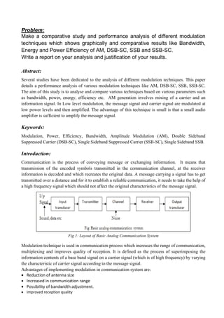
  • 1. Problem: Make a comparative study and performance analysis of different modulation techniques which shows graphically and comparative results like Bandwidth, Energy and Power Efficiency of AM, DSB-SC, SSB and SSB-SC. Write a report on your analysis and justification of your results. Abstract: Several studies have been dedicated to the analysis of different modulation techniques. This paper details a performance analysis of various modulation techniques like AM, DSB-SC, SSB, SSB-SC. The aim of this study is to analyse and compare various techniques based on various parameters such as bandwidth, power, energy, efficiency etc. AM generation involves mixing of a carrier and an information signal. In Low level modulation, the message signal and carrier signal are modulated at low power levels and then amplified. The advantage of this technique is small is that a small audio amplifier is sufficient to amplify the message signal. Keywords: Modulation, Power, Efficiency, Bandwidth, Amplitude Modulation (AM), Double Sideband Suppressed Carrier (DSB-SC), Single Sideband Suppressed Carrier (SSB-SC), Single Sideband SSB. Introduction: Communication is the process of conveying message or exchanging information. It means that transmission of the encoded symbols transmitted in the communication channel, at the receiver information is decoded and which recreates the original data. A message carrying a signal has to get transmitted over a distance and for it to establish a reliable communication, it needs to take the help of a high frequency signal which should not affect the original characteristics of the message signal. Fig 1: Layout of Basic Analog Communication System Modulation technique is used in communication process which increases the range of communication, multiplexing and improves quality of reception. It is defined as the process of superimposing the information contents of a base band signal on a carrier signal (which is of high frequency) by varying the characteristic of carrier signal according to the message signal. Advantages of implementing modulation in communication system are:  Reduction of antenna size  Increased in communication range  Possibility of bandwidth adjustment.  Improved reception quality
  • 2. The types of modulations are broadly classified into continuous-wave modulation and pulse modulation. In continuous-wave modulation, a high frequency sine wave is used as a carrier wave. This is further divided into amplitude and angle modulation. If the amplitude of the high frequency carrier wave is varied in accordance with the instantaneous amplitude of the modulating signal, then such a technique is called as Amplitude Modulation. If the angle of the carrier wave is varied, in accordance with the instantaneous value of the modulating signal, then such a technique is called as Angle Modulation. Angle modulation is further divided into frequency modulation and phase modulation. If the frequency of the carrier wave is varied, in accordance with the instantaneous value of the modulating signal, then such a technique is called as Frequency Modulation. If the phase of the high frequency carrier wave is varied in accordance with the instantaneous value of the modulating signal, then such a technique is called as Phase Modulation. Fig 2: Types of Modulation in Analog Communication System As we discussed earlier modulation is a very important process in communication systems, because the voice signal is dynamically varying signal hence need a high speed DSP processor to process the signals accurately .The modulation schemes are broadly classified into two categories such as analog and digital modulations .The topic for implementation is Amplitude modulation followed by Double Sideband Suppressed Carrier (DSB-SC), Single Sideband (SSB) and Single Sideband Suppressed Carrier (SSB-SC).
  • 3. Methodology: Amplitude Modulation: According to the standard definition, “The amplitude of the carrier signal varies in accordance with the instantaneous amplitude of the modulating signal” Which means, the amplitude of the carrier signal containing no information varies as per the amplitude of the signal containing information, at each instant. A continuous-wave goes on continuously without any intervals and it is the baseband message signal, which contains the information. This wave has to be modulated. This can be well explained by the following figures. Fig 3: Baseband Signal Fig 4: Carrier Signal Fig 5: Amplitude Modulated (AM) Signal The first figure shows the modulating wave, which is the message signal. The next one is the carrier wave, which is a high frequency signal and contains no information. While, the last one is the resultant modulated wave. It can be observed that the positive and negative peaks of the carrier wave, are interconnected with an imaginary line. This line helps recreating the exact shape of the modulating signal. This imaginary line on the carrier wave is called as Envelope. It is the same as that of the message signal. Let the modulating signal be: m(t)=Am cos (2πfmt). The carrier signal be: c(t)=Ac cos (2πfct). The modulated wave be: s(t) = [Ac + Amcos (2πfmt)] cos (2πfct) s(t)………Eq. 1 Ac and Am are the amplitudes of carrier and message signal respectively. fc and fm are frequency of carrier and message signal respectively.
  • 4. Modulating Index: A carrier wave, after being modulated, if the modulated level is calculated, then such an attempt is called as Modulation Index or Modulation Depth. It states the level of modulation that a carrier wave undergoes. Rearranging the Eq. 1 as below: s(t) = Ac [1 + (Am/Ac) cos (2πfmt)] cos (2πfct) s(t) ⇒ s(t )= Ac [1 + μ cos(2πfmt)] cos (2πfct) ………Eq. 2. Where, μ is Modulation index and it is equal to the ratio of Am and Ac. Mathematically, we can write it as: μ=Am/Ac. Bandwidth of AM Wave: It is the difference between the highest and lowest frequencies of the signal. Mathematically, we can write it as: BW = fmax - fmin. Consider the following equation of amplitude modulated wave: s(t)=Ac [1 + μ cos (2πfmt)] cos (2πfct) s(t) ⇒ s(t) = Ac cos (2πfct) + Ac μ cos (2πfct) cos (2πfmt) ⇒ s(t) = Ac cos (2πfct) + Ac μ/2cos [2π (fc + fm) t] + Ac μ/2cos [2π(fc−fm) t] Hence, the amplitude modulated wave has three frequencies. Those are carrier frequency fc, upper sideband frequency (fc + fm) and lower sideband frequency (fc - fm). BW = (fc + fm) − (fc - fm) ⇒BW=2fm Power of AM Wave: Consider the following equation of modulated wave: s(t)=Ac cos (2πfct) + Ac μ/2cos [2π (fc + fm) t] + Ac μ/2 cos [2π (fc − fm) t] Power of AM wave is equal to the sum of powers of carrier, upper sideband, and lower sideband frequency components: Pt=Pc + PUSB + PLSB We know that the standard formula for power of cos signal is: P=vrms 2 /R=(vm/√2)2 /2 Pc=(Ac/2√2)2 /R=AC 2 /2R PUSB = (Ac μ/2√2)2 /R=Ac 2 μ2 /8R PLSB = Ac 2 μ2 /8R. Pt = AC 2 /2R+ Ac 2 μ2 /8R+ Ac 2 μ2 /8R=(Ac2 /2R) (1+μ2/4+μ2/4). Pt = Pc (1+μ2/2)
  • 5. Double Sideband Suppressed Carrier (DSBSC): In the process of Amplitude Modulation, the modulated wave consists of the carrier wave and two sidebands. The modulated wave has the information only in the sidebands. Sideband is nothing but a band of frequencies, containing power, which are the lower and higher frequencies of the carrier frequency. The transmission signals contain a carrier with two sidebands (known as Double Sideband Full Carrier) as shown below: Fig 6: Sidebands of Carrier Signal However, such a transmission is inefficient. Because, two-thirds of the power is being wasted in the carrier, which carries no information. If this carrier is suppressed and the saved power is distributed to the two sidebands, then such a process is called as Double Sideband Suppressed Carrier system or simply DSB-SC. It is plotted as shown in the following figure: Fig 7: Suppressed Carrier Signal Let the modulating signal be: m(t)=Am cos (2πfmt) The Carrier Signal be: c(t) = Ac cos (2πfct) Equation for DSB-SC modulated wave: s(t)=m(t)c(t) ⇒ s(t) = Am Ac cos (2πfmt) cos (2πfct) Bandwidth of DSBSC Wave: Bandwidth (BW): BW = fmax − fmin Equation for DSB-SC modulated wave: ⇒ s(t) = Am Ac cos (2πfmt) cos (2πfct) ⇒ s(t) = Am Ac/2 cos [2π (fc + fm) t] + Am Ac/2cos [2π (fc−fm) t]
  • 6. The DSBSC modulated wave has only two frequencies. So, the maximum and minimum frequencies are (fc + fm) and (fc − fm) respectively. fmax = (fc + fm) and fmin = (fc−fm) BW = (fc + fm) − (fc−fm) ⇒ BW = 2fm. Power of DSBSC Wave: Equation for DSB-SC modulated wave: s(t) = Am Ac/2cos [2π (fc + fm) t] + Am Ac/2cos [2π (fc−fm) t] Power of DSBSC wave is equal to the sum of powers of upper sideband and lower sideband frequency components. Pt = PUSB + PLSB P = vrms 2 /R=(vm√2)2 /R PUSB = (Am Ac/2√2)2/R = Am 2 Ac 2 /8R Similarly, we will get the lower sideband same power as that of upper sideband: PLSB = Am 2 Ac 2 /8R Now, let these two sideband powers are added in order to get the power of DSBSC wave: Pt = Am 2 Ac 2 /8R+ Am 2 Ac 2 /8R ⇒ Pt = Am 2 Ac 2 /4R
  • 7. Single Sideband Modulation (SSB): The single-sideband modulation definition is a modulation which is used for transmitting information like an audio signal through radio waves. This modulation is used in radio communications by using transmitter power & more bandwidth efficiently for an alteration of AM (Amplitude Modulation). There are many radio communication devices available in the market which use single sideband radio like SSB Tx, SSB Rx, and SSB transceiver. There are several variations are used for SSB modulation like lower sideband (LSB), upper sideband (USB), double sideband (DSB), Single Sideband Suppressed Carrier (SSB SC), Vestigial Sideband (VSB), and SSB reduced carrier. Fig 8: Single Sideband Modulation (SSB) Power of SSB Wave: It is often necessary to define the output power of a single sideband transmitter or single sideband transmission. Power measurement for an SSB signal is not as easy as it is for many other types of transmission because the actual output power is dependent upon the level of the modulating signal. To overcome this a measure known as the peak envelope power (PEP) is used. This takes the power of the RF envelope of the transmission and uses the peak level of the signal at any instant and it includes any components that may be present. Obviously, this includes the sideband being used, but it also includes any residual carrier that may be transmitted. The level of the peak envelope power may be stated in Watts, or figures quoted in dBW or dBm may be used. These are simply the power levels relative to 1 Watt or 1 milliwatt respectively.
  • 8. Single Sideband Suppressed Carrier (SSBSC): The DSBSC modulated signal has two sidebands. Since, the two sidebands carry the same information, there is no need to transmit both sidebands. We can eliminate one sideband. The process of suppressing one of the sidebands along with the carrier and transmitting a single sideband is called as Single Sideband Suppressed Carrier system or simply SSBSC. It is plotted as shown below: Fig 9: Single Sideband Suppressed Carrier (SSBSC) In the above figure, the carrier and the lower sideband are suppressed. Hence, the upper sideband is used for transmission. Similarly, we can suppress the carrier and the upper sideband while transmitting the lower sideband. This SSBSC system, which transmits a single sideband has high power, as the power allotted for both the carrier and the other sideband is utilized in transmitting this Single Sideband. Let the modulating signal be: m(t) = Am cos (2πfmt) The Carrier Signal be: c(t)=Ac cos (2πfct) The equation for SSBSC is: s(t) = Am Ac/2 cos [2π (fm + fm) t]; for the upper sideband s(t) = Am Ac/2 cos [2π (f c− fm) t] s(t); for the lower sideband Bandwidth of SSBSC Wave: Since the SSBSC modulated wave contains only one sideband, its bandwidth is half of the bandwidth of DSBSC modulated wave. i.e., Bandwidth of SSBSC modulated wave = 2fm/2 = fm Therefore, the bandwidth of SSBSC modulated wave is fm and it is equal to the frequency of the modulating signal. Power of SSBSC Wave: Let the SSBSC modulated wave be: s(t) = Am Ac/2 cos [2π (fm + fm) t]; for the upper sideband s(t) = Am Ac/2 cos [2π (f c− fm) t] s(t); for the lower sideband Power of SSBSC wave is equal to the power of any one sideband frequency components. Pt = PUSB = PLSB The power of the upper sideband is: PUSB = (Am Ac/2√2)2 /R = Am 2 Ac 2 /8R The power of the lower sideband is: PLSB = Am 2 Ac 2 /8R
  • 9. Code for Output Waveforms of AM, DSBSC, SSB, SSBSC: Amplitude Modulation (AM): m = input(‘Modulation index = ‘); t = linespace(0,0.2,1000); Am = 5; % amplitude of message signal fm = 10; % frequency of message signal M = Am*cos(2*pi*fm*t); % message signal figure; subplot(4,1,1); plot(t,M); title(‘Message Signal’); xlabel(‘time(t)’); ylabel(‘Amplitude’); %% Carrier Signal : Ac = Am/m; % amplitude of carrier signal fc = 20; % frequency of carrier signal C = Ac*cos(2*pi*fc*t); % carrier signal subplot(4,1,2); plot(t, C); title(‘Carrier Signal’); xlabel(‘time(t)’); ylabel(‘Amplitude’); y = ammod(M, fc, 100, 0, Ac); % modulated signal % ammod(M,fc,fs,INI_PHASE,CARRAMP) subplot(4,1,3),plot(t, y); title(‘Modulated Signal’); xlabel(‘time(t)’); ylabel(‘Amplitude’); ylim([-20, 20]);
  • 10. Double Sideband Suppressed Carrier (DSBSC): function amplitude = dsbsc fm = input(‘Enter the value of message signal frequency:’); fc = input(‘Enter the value of carrier signal frequency: ‘); Am = input(‘Enter the value of message signal amplitude:’); Ac = input(‘Enter the value of carrier signal amplitude:’); Tm = 1/fm; Tc = 1/fc; t1 = 0:Tm/999:6*Tm; message_signal = Am*sin(2*pi*fm*t1); subplot(3,1,1) plot(t1, message_signal, ‘r’); grid(); title(‘Message signal’); carrier_signal = Ac*sin(2*pi*fc*t1); subplot(3,1,2) plot(t1, carrier_signal,’b’ ); grid(); title(‘Carrier Signal’); amplitude = message_signal.*carrier_signal; subplot(3,1,3) plot(t1,amplitude,’g); grid(); title(‘DSBSC’); end
  • 11. Single Sideband Modulation (SSB): function SSBAM td = input(‘n Enter the total Signal Durationnn ->’); ts = input(‘n Enter the sampling time for this signal and it should be less than 1nn ->’); fc = input(‘ n Enter the carrier frequency of the cosine wave nn ->’); k = input(‘n Enter the constant diminishing factor nn->’ ); %fs = 1/ts ; t = 0:ts:td; t2 = int64( (t/ts) +1 ); m(t2) = input(‘ n Enter the msg signal as a function of time “t”; nn ->’); w(t2) = hilbert(m(t2)); c = cos((2*pi*fc*t)); cp = sin((2*pi*fc*t)); s(t2) = (c.*(1+k*m(t2))+cp.*(1+k*w(t2))); u(t2) = (1+k*m(t2)).*c; subplot(2,1,1),plot(t,s(t2)); grid minor title(‘Single SideBand Modulation’) subplot(2,1,2),plot(t,u(t2)); title(‘DSB Signal’) grid minor d = input(‘ n IF FUNCTION OF FOURIER TRANSFORM IS NEEDED PRESS “1” nn ->’); if d==1 syms t; M = input(‘ n REENTER THE MESSAGE SIGNAL AS A FUNCTION OF TIME BUT FOR THE INFINITE TIME PERIODnn ->’); U = (1+k*M)*(1/2)*(cos(2*pi*fc*t) + abs(cos(2*pi*fc*t))); FourierTransform = fourier(U) end
  • 12. Single Sideband Suppressed Carrier (SSBSC): function am = ssbsc Am = input(‘Enter the value of message signal Amplitude:’); Ac = input(‘Enter the value of carrier signal Amplitude:’); fm = input(‘Enter the value of message signal frequency:’); fc = input(‘Enter the value of carrier signal frequency:’); m = Am/Ac; A = (m*Ac); Tm = 1/fm; Tc = 1/fc; t = 0:Tm/999:6*Tm; message_signal = Am*sin(2*pi*fm*t); carrier_signal = Ac*sin(2*pi*fc*t); x1 = cos(2*pi*fc*t).*cos(2*pi*fm*t); x2 = sin(2*pi*fc*t).*sin(2*pi*fm*t); x3 = x1+x2; x4 = x1-x2; SSBSC_lsb = A*(x3); SSBSC_usb = A*(x4); subplot(4,1,1) plot(t, message_signal, ‘r’); grid(); title(‘message signal’); subplot(4,1,2) plot(t, carrier_signal , ’g’); grid(); title(‘Carrier signal’); subplot(4,1,3) plot(t, SSBSC_lsb,’b’); grid(); title(‘LSB of SSBSC wave cutting off USB’); subplot(4,1,4) plot(t, SSBSC_usb, ‘r’); grid(); title(‘USB of SSBSC wave cutting off LSB’); end
  • 13. Results: The basic research work carried out in the field of communication lead to the development of new modulation techniques, error performances analysis, having immunity to noise but the ever-increasing demand of the faster communication system with large bandwidth requirements and transmitted power has again generated a new requirement towards the development of newer techniques. The comparison table for various parameters for AM, DSBSC, SSB, and SSBSC is shown below: Parameters AM DSBSC SSB SSBSC Variable Characteristics Amplitude Amplitude Amplitude Amplitude Sideband Suppression No No One Sideband Completely One Sideband Completely Carrier Suppression No Complete Any One Sideband Complete Modulating Input 1 1 1 1 Bandwidth 2fm 2fm fm fm Transmission Efficiency Low Moderate Maximum Maximum Power High Medium Low Low Complexity Simple Simple Complex Highly Complex Performance in presence of noise Low Average Average Merits Easy detection Low power consumption, simple modulation system Bandwidth efficiency, reduction in distortion Low power consumption, Better frequency use Demerits Poor reception quality, Complex detection Complex detection Complex detection Table 1: Comparison of various parameters of AM, DSBSC, SSB and SSBSC Conclusion: An analysis of the modulation techniques carried out in this article reveals that the selection of a analog modulation technique is solely dependent on the type of application. This is because of the fact that some of the technique provide lesser complexities in the design of the modulation and demodulation system and prove to be economic. Single sideband modulation, (SSB) is the main modulation format used for analogue voice transmission for two-way radio communication on the HF portion of the radio spectrum. Its efficiency in terms of spectrum and power when compared to other modes means that for many years it has been the most effective option to use. Now some forms of digital voice transmission are being used, but it is unlikely that single sideband will be ousted for many years as the main format used on these bands.
  • 14. References: 1) Lathi, B.P., “Modern Digital and Analog Communication,” Oxford University Press, New York, 1998. 2) ANALOG AND DIGITAL COMMUNICATION LABORATORY by Prof Shaik Aqeel, Electronics and Telecommunication Engineering, Sreyas Institute of Engineering and Technology, February 24, 2021. 3) John G. Proakis and Masoud Salehi, “communication systems engineering”, 2nd Ed, prentice hall, 2001. 4) Chapter 5, Traditional Analog Modulation Techniques, Mikael Olofsson, 2002-2007. 5) K. Sharma, A. Mishra & Rajiv Saxena, „Analog & Digital Modulation Techniques: An overview‟, international Journal of Computing Science and Communication Technologies, VOL. 3, NO. 1, July 2010. 6) Schwartz, M.: Information Transmission, Modulation and Noise, McGraw-Hill, New York, 1990.