Estudo do líquido percolado da leira de compostagem
Design notes
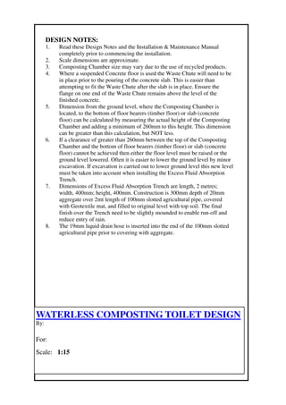
1. DESIGN NOTES:
1. Read these Design Notes and the Installation & Maintenance Manual
completely prior to commencing the installation.
2. Scale dimensions are approximate.
3. Composting Chamber size may vary due to the use of recycled products.
4. Where a suspended Concrete floor is used the Waste Chute will need to be
in place prior to the pouring of the concrete slab. This is easier than
attempting to fit the Waste Chute after the slab is in place. Ensure the
flange on one end of the Waste Chute remains above the level of the
finished concrete.
5. Dimension from the ground level, where the Composting Chamber is
located, to the bottom of floor bearers (timber floor) or slab (concrete
floor) can be calculated by measuring the actual height of the Composting
Chamber and adding a minimum of 260mm to this height. This dimension
can be greater than this calculation, but NOT less.
6. If a clearance of greater than 260mm between the top of the Composting
Chamber and the bottom of floor bearers (timber floor) or slab (concrete
floor) cannot be achieved then either the floor level must be raised or the
ground level lowered. Often it is easier to lower the ground level by minor
excavation. If excavation is carried out to lower ground level this new level
must be taken into account when installing the Excess Fluid Absorption
Trench.
7. Dimensions of Excess Fluid Absorption Trench are length, 2 metres;
width, 400mm; height, 400mm. Construction is 300mm depth of 20mm
aggregate over 2mt length of 100mm slotted agricultural pipe, covered
with Geotextile mat, and filled to original level with top soil. The final
finish over the Trench need to be slightly mounded to enable run-off and
reduce entry of rain.
8. The 19mm liquid drain hose is inserted into the end of the 100mm slotted
agricultural pipe prior to covering with aggregate.
WATERLESS COMPOSTING TOILET DESIGN
By:
For:
Scale: 1:15