
Recomendados
Mais conteúdo relacionado
Mais procurados
Mais procurados (20)
Semelhante a B tech project 2
Semelhante a B tech project 2 (20)
Mais de Pei Di
Último
Último (20)
B tech project 2
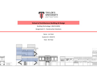
- 1. Name : Lim Peidi Student ID : 0324272 Tutor : Mr. Rizal School of Architecture Building & Design Building Technology 1 (BLD 61403) Assignment 2 – Construction Solutions
- 2. Content 1.0 Site Introduction 2.0 Precedent Studies - Roof System (Gable Roof) - Façade System (Perforated Mesh Screen) - Façade System (Translucent Corrugated Screen) - Structural System (Steel Framing Structure) 3.0 Façade Design Scheme - Perforated Mesh Screen - Translucent Corrugated Screen 4.0 Sectional Perspectives 5.0 Conclusion 6.0 References 1 – 2 3 – 11 12 – 16 17 – 23 24 -25 24 - 25
- 3. 1.0 Site Introduction - Site Location - Design Intention - Design Consideration through Construction 1
- 4. Project Name : Community Learning Centre Location : Jalan Stesen 1, Klang Function : Learning Centre Introduction to Site Design Intention This area is an area which is being resuscitated in a sense to bring local community back together. There are a lot of boundaries in between the local community. The shopfront community and the back-alley community, the youngsters and the elderlies, the old face of Klang and the new faces to bring into Klang. Rethinking about the area and of course the needs of local community to communicate and interact, this learning centre forms and anchor and connection so that the people can gather here and strengthen the community. Design Consideration Through Construction In order to anchor down the connection in between community, there is a need of certain degree of visual permeability towards the learning centre. Hence, perforated mesh screen and translucent corrugated screen façade system are proposed. For the roof construction system, gable roof is proposed as it’s the roof profile from site. The learning centre adapt the roof profile to have a continuity and similar language with the site context. In order to anchor the relationship of young and old, not just through remaining the old elements but also to add in new elements. Hence, steel structure which is a post-modern construction design is introduced. Site Plan NTS 2
- 5. 2.0 Precedent Studies - Roof System (Gable Roof) - Façade System (Perforated Mesh Screen) - Façade System (Translucent Corrugated Screen) - Structural System (Steel Framing Structure) 3
- 6. Introduction Project Name : A Gable Roof in Kawagoe Location : Kawagoe, Japan Architects : Tailored design lab Project Year : 2014 Area : 250 sqm Structure : Timber gable roof Roof System Construction System Type Timber Structural Roof Framing Materials Timber, Metal deck roofing Advantages 1. Cost effective in building 2. Weather resistance 3. Provides slopes for water to drains off 4. Opportunity for additional floor space in roof volume Disadvantages 1. Ventilation Issues 2. Aesthetic considerations Design Consideration 1. Direction of gable roof 2. Apertures & Sloppiness of roof plane 3. Choice of materials to be done wisely. 4. Well insulated roof with reflective finishes should be considered Roof System Application Design Relevance to Studio V Project Allows Daylighting 45 – degree roof Is selected to create large interior space and an efficient structure. A fully glassed gable allows dynamic views to the rural landscape and emphasizes the perspective from north to south Gable roof system allows a designated perspective for users in the building. Besides, in order to continue the skyline at site, there’s a limited building height. Therefore, gable roof helps to create more interior spaces with a lower height Larger Interior Spaces Avoid Direct Sunlight Slope for water to drain off 4
- 7. Construction Details 1. Ridge 2. Ladder frame 3. Common rafters 4. Purlin built into gable wall 5. Wallplate 6. Plywood gusset 7. Tilting fillet 8. Barge board fixed to last rafter 9. Gable wall Construction Process 1. The orientation of roof were determined so that the gable glass were facing the direction with more views and to avoid direct sunlight into the building. 2. The measurement and size of roof is determined 3. Timber roof framing components were fabricated off site and the assemblage of timber roof framing were constructed on site. 4. Roof is built in 45- degree and a 105mm x 105mm simple framework is made of 2 x 12 rafters spaced 455mm apart. 5. Structural plywood is used for earthquake resistance. 6. Roofing layers were applied to help in insulation and water to flow off the roof. Gutters were installed for roof drainage. 7. First piece of roof covering panel were placed along the edge of the roof. The remaining panel were laid overlapping one and another. Screws were placed into overlapping panels. Roof System Sample of construction process of gable roof on site 5
- 8. Introduction Project Name : Taiwanese Townhouse Location : Taipei, Taiwan Architects : KC Design Studio Project Year : 2016 Area : 80 sqm Structure : Perforated Mesh Screen Facade System – Perforated Mesh Screen Construction System Type Double Skin Façade with Perforated Mesh Screen Materials Aluminium Composite Material, Corten Steel Advantages of Perforated Screen 1. Aesthetic With virtually endless options in holes shapes, size & geometric pattern, perforated screen adds visual interest to the building’s exterior. It allows occupants to enjoy exterior view while maintaining a certain degree. Allowing a comfortable level of natural lighting during the day, perforated screen reduces the amount of artificial lighting needed, while at the same time deflects heat. 2. Versatility Aluminum perforated screen used is versatile. It used as lightweight decorative element for the building. It allows a multitude of options to explore. For example, screen as sunscreens that filter lights, railing infills that add structure while reducing mass, enhance aesthetics of buildings etc. Disadvantages 1. Connections have to be carefully sealed and waterproofing need to be done to avoid water penetration into building during rain Design Consideration 1. Privacy of spaces 2. Suitability to site context 3. Durability Perforated aluminum screen able to withstand harsh weather environments, with the ability to control the pressure. The perforation also decreases the weight needed to be supported by the building’s framework. 4. Energy Efficient Perforated aluminum screen allows the balancing of light & ventilation. By deflecting heat, less energy output is required, providing a more consistent interior temperature. As a screening element, perforated metal decreases the amount of indoor lighting required. 5. Eco – Friendly Minimize resource depletion due to its recyclability, reduces energy in use, promotes sustainability . Perforations decrease amount of metal used, which translates to reduced weight and lower fuel transportation costs to building site 6
- 9. Construction Details of Façade 1. Perforated Mesh 2. Steel Façade Structure 3. Beam 4. Steel Galvanized Gutter Facade System Application Site context relationship to the building to allow design of facade Allows light penetration into building , able to see partially of the interior Allows direct sunlight to the building. Voids in façade system. To keep the privacy of the spaces Proximity arrangement of townhouses 1 2 3 4 3mm Corten Steel Perforated Mesh 60mm Bracket Steel Plate to screwed steel façade structure to concrete beam Design Relevance to Studio V Project The façade system provides a permeable building envelope. It allows light penetration of sunlight and ventilation to the building to enhance the experiences in Learning Centre’s spaces such as workshops & library. The perforated aluminum also gives a sense of curiosity to the passersby. The façade system also controls the privacy of the building yet allows visual engagement between the occupants and the streets, suiting the concept of the learning center – anchoring the relationship between interior & exterior. Facade System – Perforated Mesh Screen 7
- 10. Introduction Project Name : Nest We Go Location : Hokkaido, Japan Architects : Kengo Kuma & Associates Project Year : 2014 Area : 85 sqm Structure : Translucent Corrugated Screen Facade System – Translucent Corrugated Screen Construction System Type Double Skin Façade with translucent corrugated screen Materials Translucent Corrugated Panel, Steel Framing Strcuture Advantages of Corrugated Screen 1. Aesthetic Translucent perforated screen allows certain degree of exterior view towards the interior while maintaining the privacy. The translucent screen allows comfortable level of natural lighting into the building during the day. This natural lighting allows the building to have a lesser amount of artificial lighting. At night, lights from the interior shines out to the exterior and gives a pleasant view for the passer-by. 2. Durability Virtually unbreakable and can withstand massive force. Besides, corrugated screen are light weight materials which help to reduce the weight to be supported by building’s framework Disadvantages 1. Corrugated screen are not very resistant t scratching & marring. As a result, denting is possible on the surface if care is not taken 2. Manufacturing process is not environmental friendly as it requires a very high processing temperatures. 3. Highly sensitive to organic solvents. Hence, maintenance work need to be careful Design Consideration 1. Privacy of spaces 2. Suitability to site context 3. Cost Effective Light weight compared to glass, acrylic or other plastics. This results in easy transportation, installation and lower lab costs which is a big consideration for building cost 4. Energy Efficient Translucent corrugated screen allows ultraviolet blockage while allowing sufficient light into the building. It saves the energy cost in the morning by providing natural sunlight into the building. 5. Weather Resistance Corrugated screen has high resistance to sunlight and rain. This enables the panels to last in the outdoors for many years without showing signs of fading, yellowing or discoloration. 8
- 11. Facade System – Translucent Corrugated Screen Facade System Application Translucent corrugated façade screen is used in consideration the climate on site Winter & Summer Sun 1 Design Relevance to Studio V Project The façade system provides a visual curiosity for the local community. A whole new building element that is different from the existing site façade, this façade screen enable the learning center to stand out and catch attention of people. Plus, the light penetration in the building suites the courtyard typology which allows natural lighting into the building. Wind Rain 2 3 4 5 6 Construction Details of Façade 1. Slope roof : Translucent Corrugated Panel 2. Exterior envelope : Translucent Corrugated Panel 3. Sliding Window : translucent Corrugated Panel 4. Handrail : Rope 5. Wood Panel 6. Concrete Wall Head Connection Detail Sill Connection Detail Jamb Connection Detail Corrugated Panel Connection Detail Thermally Broken Framing Deep rabbets for thermal expansion Low friction gasketing Translucent Corrugated Panel Weep Holes Fastener Sill Flashing Perimeter Seal Removable Stop Gasket Panel Joint Interface Translucent Corrugated PanelReinforcing Panel 9
- 12. Introduction Project Name : Noxx Apartment Location : Istanbul, Turkey Architects : CM Architecture Project Year : 2013 Area : 128 sqm Structure : Steel Structure Structural System – Steel Structure Construction System Type Steel structure with H column and I beam, connected with Plywood flooring Materials H column , I beam , Plywood Flooring Advantages 1. High compressive resistance & possesses high tensile strength 2. Able to withstand extensive dead and live load 3. Fast fabrication & construction process 4. Termite proof Disadvantages 1. High maintenance cost 2. Little fire resistance 3. Corrosion might occur Design Consideration 1. Weather and fire proof of steel structure due to the hot and humid climate of Klang which might cause corrosion of structure 2. Bracing elements can be used to help in load transfer in steel structure Plywood Flooring Steel Construction – I Beam & H Column Internal wall – Gypsum Wall Cladding Front façade – Glass, Aluminum External wall – Brick wall Plywood flooring Steel Structure Stairs – Wood on Steel External wall – Brick wall Plywood flooring 10
- 13. Design Relevance to Studio V Project Steel structure system allows large span between columns and creates a larger open spaces within the learning centre which subsequently allowing the flexibility of the learning centre spaces. Besides, steel framing structure is proposed as it is able to accommodate more horizontal forces and provide a more flexible design for the learning centre. Structural System – Steel Structure 1 Construction Details of Façade 1. Brick Wall 2. Plywood (24mm) 3. Gypsum Cladding 4. Aquapanel Cladding 5. Plaster 6. Stone Claddig + Mortar with Reinforced Concrete Slab Primary Beam Primary Beam Secondary Beam Secondary Beam Shear Tab Grout Pack RC Pad Footing Reinforcement bar Steel Column Base Plate Holding down bolts 2 3 45 6 Foundation To Column Detail Primary Beam to Secondary Beam Detail Column to Beam Detail Angle Clip Metal End Plate H Column I Beam 11
- 14. 3.0 Façade Design Scheme - Perforated Mesh Screen - Translucent Corrugated Screen 12
- 15. Perforated Mesh Screen Front Elevation Scale 1 : 100 Façade Design Scheme 1 13
- 16. Perforated Mesh Screen Rear Elevation Scale 1 : 100 Façade Design Scheme 1 14
- 17. Translucent Corrugated Screen Front Elevation Scale 1 : 100 Façade Design Scheme 2 15
- 18. Translucent Corrugated Screen Rear Elevation Scale 1 : 100 Façade Design Scheme 2 16
- 19. 4.0 Sectional Perspectives - Foundation to Column Detail - Column to Beam Detail - Primary Beam to Secondary Beam Detail - Façade Detail - Composite Floor Slab Detail - Gable Roof Detail - Flat Roof Detail 17
- 20. Sectional Perspectives Sectional Perspective NTS Foundation to Column Detail Column to Beam & Primary Beam to Secondary Beam Detail Façade Detail Composite Floor Slab Detail Gable Roof Detail Flat Roof Detail 18
- 21. Sectional Perspectives Lower Floor Sectional Perspective NTS Foundation to Column Detail Column to Beam & Primary Beam to Secondary Beam Detail 19
- 22. Construction Details Foundation to Column Detail 305mm x 305mm Steel H column Perspective Section Stiffeners to stiffen the column against deformation Base Plate to connect concrete column stump with steel column Concrete Column Stump 305mm x 305mm Steel H column Column Stump Nut Base Plate Grout Bolt Column to Beam Detail Primary Beam to Secondary Beam Detail Detail A Perspective Section 305mm x 102mm Primary Beam 305mm x 305mm H ColumnFin Plates Connection as it is economical to fabricate and simple to erect Fin Plate Gap Column Beam 100mm x 10mm Fin Plate with 1 Vertical Bolt Line 20
- 23. Sectional Perspectives Upper Floor Sectional Perspective NTS Façade Detail Gable Roof Detail 21 Flat Roof Detail Composite Floor Detail Façade to Column Detail
- 24. Construction Details Façade Detail Detail A Detail B Detail C Frame Detail Perspective Sill Flashing Sill flashing sloped from interior. Shimmed accordingly Thermal Break Provides better insulation value for the air-conditioned space Construction Details 1. Translucent Corrugated Panel 2. Façade Structure Frame Glazing Clips Placed along translucent corrugated panel joints. Size varies depends on load requirement Translucent Corrugated Panel 500mm thick panel with tongue & groove joinery to provide clean appearance without vertical framing Gable Roof Detail Detail A Detail C Detail B 1 2 Ridge Beam C-shape member inside track section. Fasten through to & bottom flanges with screws Perspective Detail 1 Detail 1 Clip Angle Rafter Purlin PurlinSteel Rafter Ridge Beam Tie To withstand the roof from load on roof and to provide more spaces below 22 H Column Façade Frame Clips Column to Façade Frame Connection
- 25. Construction Details Flat Roof Detail Composite Floor Slab Detail 305mm x 102mm I Beam Metal Decking Profile Shear Studs Rebar Mesh160mm Concrete Slab Perspectives Section 160mm Concrete Slab with Rebar Mesh Metal Decking Primary Beam I Beam Beam Brackets Secondary BeamMetal Deck Web Joist Truss Bridging Truss To increase the stability of roof Joist Seat welded to the roof beam Metal Deck is screwed to the Web Joist Truss Concrete Finishing Open Web Joist Roof Beam Column Joist Seat bolted to the column using fin plate 23
- 26. 5.0 Conclusion & 6.0 References 24
- 27. Conclusion All in all, both structural and architectural space quality should be taken into consideration at the same time as both are quite crucial in affecting the functional and aesthetic of the building. Losing either one of these elements will not make the architecture perfect. Choices of structural system, façade and roof connection is selected wisely to complement the design of the learning centre and provide a unique and interesting experience for the users References 1. /author/jon-henderlong. (2001, March 01). Framing Roofs With Steel. Retrieved from https://www.jlconline.com/how-to/framing/framing-roofs- with-steel_o?o=0 2. A Gabled Roof in Kawagoe / Tailored design Lab. (2015, October 21). Retrieved from https://www.archdaily.com/775667/a-gabled-roof-in-kawagoe-tailored- design-lab 3. Ann-house. (2014, November 19). ROOF SLOPES. Retrieved from https://www.slideserve.com/ann-house/roof-slopes 4. Crook, L. (2017, August 07). KC Design Studio adds perforated facade and atrium to skinny Taiwanese townhouse. Retrieved from https://www.dezeen.com/2017/03/15/kc-design-studio-perforated-facade-atrium- skinny-taiwanese-house/ 5. Lindapter. (n.d.). Facade & Cladding[Brochure]. Author. Retrieved November 15, 2018. 6. NoXX Apartment / CM Architecture. (2015, February 03). Retrieved from https://www.archdaily.com/593084/noxx-apartment-cm-architecture 7. Simple connections. (n.d.). Retrieved from https://www.steelconstruction.info/Simple_connections 25