Paul Ahern - Piezoelectric Energy Harvesting Review
•
6 gostaram•6,890 visualizações

Mechanical energy is among the most plentiful and consistent energy sources in our day-to-day lives, which is available to us regardless of the whims of the weather or the cycles of day and night. Piezoelectric Energy Harvesters (PEH’s) are compact devices which allow the scavenging of low grade energy from ambient sources such as human and environmental vibrations, with the aim of using this energy to power autonomous electronic devices. Many decades of research and development in the field has led to commercially available devices based on piezoelectric materials which can be used to harvest milliwatts of energy from mechanical sources such as vibration, stress or strain.
![Paul Ahern, ie.linkedin.com/in/paulahern1/ Piezoelectric Energy Harvesting
arciphel@gmail.com
2 | P a g e
References ........................................................................................................................................22
Introduction
Mechanical energy is among the most plentiful and consistent energy sources in our day-to-day
lives, which is available to us regardless of the whims of the weather or the cycles of day and night.
Piezoelectric Energy Harvesters (PEH’s) such as the one shown in figure 1 below, are compact
devices which allow the scavenging of low grade energy from ambient sources such as human and
environmental vibrations, with the aim of using this energy to power autonomous electronic
devices. Many decades of research and development in the field has led to commercially available
devices based on piezoelectric materials which can be used to harvest milliwatts of energy from
mechanical sources such as vibration, stress or strain.
Figure 1 – An energy harvesting device resting on top of a one cent coin
(Image courtesy of Erkan Aktakka / University of Michigan News Service).
These devices are ideal as a replacement for small batteries to power wireless, autonomous
sensors and networked devices. The growing number of companies supplying piezoelectric
materials to industry is also leveraging their knowledge to tap into this new market segment, with a
major driver being the need to find power sources for autonomous sensor networks and ubiquitous
communication networks which typically are required to operate far from the comfort of the
traditional power grid.
A good example of this type of sensor network would be GLACSWEB, a project undertaken
by the University of Southampton to deploy a low power, survivable wireless sensor network to
monitor glacial ice behaviour [1]. Two networks are already in place in Norway and Iceland so far,
with a third network being planned for use in Tijuana, Mexico to act as an early warning system for
landslides. The challenges arise in trying to mature this technology to make it compatible with a
wide variety of service environments and applications, and so it can run with no intervention for a
long time with high uptime and reliability.](data:image/gif;base64,R0lGODlhAQABAIAAAAAAAP///yH5BAEAAAAALAAAAAABAAEAAAIBRAA7)
Recomendados
Mais conteúdo relacionado
Mais procurados
Mais procurados (20)
Destaque
Destaque (20)
Semelhante a Paul Ahern - Piezoelectric Energy Harvesting Review
Semelhante a Paul Ahern - Piezoelectric Energy Harvesting Review (20)
Último
Último (20)
Paul Ahern - Piezoelectric Energy Harvesting Review
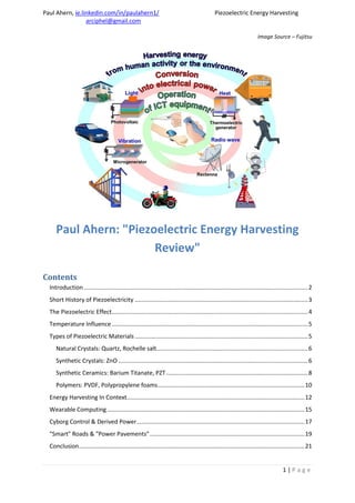
- 1. Paul Ahern, ie.linkedin.com/in/paulahern1/ Piezoelectric Energy Harvesting arciphel@gmail.com 1 | P a g e Image Source – Fujitsu Paul Ahern: "Piezoelectric Energy Harvesting Review" Contents Introduction ........................................................................................................................................2 Short History of Piezoelectricity .........................................................................................................3 The Piezoelectric Effect.......................................................................................................................4 Temperature Influence .......................................................................................................................5 Types of Piezoelectric Materials .........................................................................................................5 Natural Crystals: Quartz, Rochelle salt............................................................................................6 Synthetic Crystals: ZnO ...................................................................................................................6 Synthetic Ceramics: Barium Titanate, PZT......................................................................................8 Polymers: PVDF, Polypropylene foams.........................................................................................10 Energy Harvesting In Context............................................................................................................12 Wearable Computing........................................................................................................................15 Cyborg Control & Derived Power......................................................................................................17 "Smart" Roads & "Power Pavements"..............................................................................................19 Conclusion.........................................................................................................................................21
- 2. Paul Ahern, ie.linkedin.com/in/paulahern1/ Piezoelectric Energy Harvesting arciphel@gmail.com 2 | P a g e References ........................................................................................................................................22 Introduction Mechanical energy is among the most plentiful and consistent energy sources in our day-to-day lives, which is available to us regardless of the whims of the weather or the cycles of day and night. Piezoelectric Energy Harvesters (PEH’s) such as the one shown in figure 1 below, are compact devices which allow the scavenging of low grade energy from ambient sources such as human and environmental vibrations, with the aim of using this energy to power autonomous electronic devices. Many decades of research and development in the field has led to commercially available devices based on piezoelectric materials which can be used to harvest milliwatts of energy from mechanical sources such as vibration, stress or strain. Figure 1 – An energy harvesting device resting on top of a one cent coin (Image courtesy of Erkan Aktakka / University of Michigan News Service). These devices are ideal as a replacement for small batteries to power wireless, autonomous sensors and networked devices. The growing number of companies supplying piezoelectric materials to industry is also leveraging their knowledge to tap into this new market segment, with a major driver being the need to find power sources for autonomous sensor networks and ubiquitous communication networks which typically are required to operate far from the comfort of the traditional power grid. A good example of this type of sensor network would be GLACSWEB, a project undertaken by the University of Southampton to deploy a low power, survivable wireless sensor network to monitor glacial ice behaviour [1]. Two networks are already in place in Norway and Iceland so far, with a third network being planned for use in Tijuana, Mexico to act as an early warning system for landslides. The challenges arise in trying to mature this technology to make it compatible with a wide variety of service environments and applications, and so it can run with no intervention for a long time with high uptime and reliability.
- 3. Paul Ahern, ie.linkedin.com/in/paulahern1/ Piezoelectric Energy Harvesting arciphel@gmail.com 3 | P a g e Business consultants IDTechEx estimate that the amount of money spent on piezoelectric energy harvesting will grow to US$145 Million by the year 2018, giving rise to a market estimated to be worth close to $670 Million by the year 2022[2]. This predicted market will be served by close to 200 different types of piezoelectric materials which can be tailored to the required application environment and power generation need, with new materials still be discovered and created. The most common piezoelectric material, lead zirconate titanate, more commonly known as “PZT”, continues to be popular but organic materials which have better temperature performance and improved flexibility such as polyvinylidene difluoride (PVDF)[3] can expect to garner a share of the emerging market also. Piezoelectric materials which harvest energy from vibration output that electrical charge as an alternating current so therefore need to be run through further devices to give a usable DC output. Another question is that of oscillation frequency, as the optimal amount of energy available can only be captured when the beam is vibration at, or very close to, it’s resonant frequency and falls off sharply with a frequency shift. One approach to negate this effect is to pre-bias the piezoelectric material which can lead to increased power output but is challenging to control. Short History of Piezoelectricity Piezoelectrics are a family of materials that exhibit a very special property – when the material is deformed by either squeezing or stretching, an electric charge is created by what is known as the “piezoelectric effect”. Pierre and Jacques Curie were the first to discover the piezoelectric effect in 1880 by measuring surface charges which were demonstrated on specially arranged crystalline salts of naturally occurring materials such as cane sugar, Rochelle salt and quartz[4]. The term “piezoelectricity” was subsequently coined by the German mathematician Hermann Hankel, coming from the Greek word “piezen” which means “to press”*5+. One important aspect of the Curie brother’s work was that not only had they chosen specific materials which they believed would show the piezoelectric phenomenon, but also they realised that the crystalline orientation of those materials was just as important in creating the conditions for electricity to be created from mechanical deformation of the material. One thing that they did not realise was the reciprocal nature of the phenomenon and the importance of the inverse (or converse) piezoelectric effect - that of creating a stress in the material by the application of a voltage – this was later proved mathematically from thermodynamic principals by Gabriel Lippman in 1881 and experimentally confirmed by the Curies in practice one year later[6]. In 1920 W. G. Cady filed the patent for the piezoelectric resonator[7], realising the radio frequency applications of piezoelectric crystals oscillating near their resonant frequency. In 1935 the piezoelectric effect was demonstrated in potassium di-hydrogen phosphate (KDP), which was the first major “family” of commercially viable piezoelectric and ferroelectric materials to be discovered. The onset of World War II saw increased research by both the US, USSR and Japan which led to the post-war creation of artificial piezoelectric materials such as barium titanate and lead zirconate titanate which were first synthesised in the 1950’s by sintering metallic oxide powders, with synthetic quartz[8] becoming available for the first time in 1958 by the use of the autoclaved hydrothermal process.
- 4. Paul Ahern, ie.linkedin.com/in/paulahern1/ Piezoelectric Energy Harvesting arciphel@gmail.com 4 | P a g e In the mid 1960’s several Japanese companies pioneered the R&D of novel piezoelectric materials and were successful in opening up new commercial avenues for these products which have continued to drive forward materials research to the present day, with piezoelectric materials finding use in industries as diverse as medicine to automotive to telecommunications as well as military applications. In the last two decades there has been growing interest and numerous research initiatives into the use of these materials for energy harvesting and sensor array powering applications, with the rate of advances in this field accelerating rapidly in the last five years. The Piezoelectric Effect To fully understand this effect, we need to view the material at its molecular level. Each molecule within the crystalline material has a dipole polarisation, with one end of the molecule positively charged and the other end negatively charged. In a monocrystalline material, all of these dipoles are aligned in the same direction so the crystal can be described as being symmetrical. When the material is polycrystalline, these dipoles are orientated in different directions and the material is thus asymmetrical. Applying an electric field, as represented in figure 2 below, to heat the piezoelectric material imparts enough energy to drive re-organisation of the dipoles such that they all face in the same direction, and the material is now symmetrical. Figure 2 - Illustration of the piezoelectric effect in a polarised ceramic material[9]. The first image shows the material in its initial, unpolarised state, composed of cells of arbitrary direction. The middle image shows it after being polarised by the application of a strong DC electric field. The last image shows the remnant polarity, which it retains even when the electric field has been removed, and it can now be used as a piezoelectric material. One very important material property for piezoelectric elements is the coupling factor, k, which is the relationship between the magnitudes of mechanical and electrical power when the piezoelectric element changes energy from one state into another. In simple terms, it can be thought as a good measurement of the efficiency of energy conversion between these two states. Figure 3 below shows the directions of the forces which affect a piezoelectric element.
- 5. Paul Ahern, ie.linkedin.com/in/paulahern1/ Piezoelectric Energy Harvesting arciphel@gmail.com 5 | P a g e Figure 3 – Directions of forces affecting a piezoelectric element[10]. Directions <x>, <y> and <z> are represented by vectors 1,2 and 3 respectively. Moments 4,5 and 6 are shearing forces which occur in rotation around these vectors. When k is quoted, for instance in a manufacturer’s technical data sheet, it is often underscored with two numerical values which describe the energy conversion magnitude in different fixed axes. The first number is the plane along which the electrodes are placed, and the second refers to the plane in which the mechanical deflection is generated, or inputted. As a convention, the polarity direction is normally set to be parallel with the <z> axis. So for instance, referring to k31 means the value for the coupling of the electric field in direction 3 with longitudinal vibration in direction 2. Values quoted by manufacturers are generally mathematically modelled maximum values, with real-world values likely to be between 25% and 75% depending on the frequency of oscillation and the piezoelectric material used. Temperature Influence Temperature plays an important part of the behaviour of piezoelectric materials. These materials have a characteristic temperature, known as the Curie temperature. Above this Curie point, each micro crystal into the overall macro material reverts to a cubic orientation with a loss of polarisation as there is no longer any dipole moment present[11] and enter a state where they are referred to as being paraelectric or “depoled”. The Curie temperature of Quartz is 573°C, but for PZT is only 250°C and significant performance degradation can be seen even when temperatures of only 150°C are reached[12]. PZT will not self- re-polarise at room temperature after heating above it’s Curie temperature, but can be repolarised through the original polling mechanism by re-application of a strong electric field. Types of Piezoelectric Materials Piezoelectric materials may be divided into the categories of Natural Crystals, Synthetic Crystals, Synthetic Ceramics and Polymers. Since a piezoceramic is at the microscale composed of a random grain structure of multiply-orientated crystals which have a majority of aligned dipoles, in the strictest sense they should be referred to as exhibiting a “polarised electrostrictive effect”, as
- 6. Paul Ahern, ie.linkedin.com/in/paulahern1/ Piezoelectric Energy Harvesting arciphel@gmail.com 6 | P a g e technically a material should be composed of a single monolithic crystal to be a classic piezoelectric[13]. Natural Crystals: Quartz, Rochelle salt Quartz is one of the original piezoelectric materials and still has many advantages – it can be readily produced synthetically, can withstand temperatures up to 400°C and can be cut in pre-determined crystalline planes to maximise it’s sensitivity to incoming pressure or shear forces. They can be oscillated at high frequencies but demonstrate low magnitudes of deflection. A subsection of quartz is calcium gallogermanate isotopes[14], which can withstand temperatures up to 1300°C and are also highly sensitive, making them ideal for use in applications such as sensors and actuators for engines, however their cost is extremely high. Rochelle salt (chemical name Potassium sodium tartrate) is named after the French seaside town where it was first synthesised by chemist Pierre Seignette in 1675. Not to be confused with common table salt (NaCl), Potassium sodium tartrate and the similar monopotassium phosphate were amongst the earliest materials known to display the phenomenon of piezoelectricity[15]. Synthetic Crystals: ZnO Zinc Oxide is familiar as an insoluble white powder widely used as an additive in a huge array of manufactured goods; but as a material it is its properties as a wide bandgap III-VI material that appeals to us for application in piezoelectrics. This has seen ZnO used in LCD and LED technology as well as an energy saving thin film. In 2006 Wang and Song demonstrated[16] that an array of ZnO nanowires, as shown in figure 4 below, could be used to harvest mechanical energy and to power devices at the nanoscale, with the power generated by the strain field created by coupling of the semiconducting and piezoelectric characteristics of the ZnO array as a result of it’s deformation and the establishment of a persistent Schottky barrier between the metal wires and the ZnO substrate.
- 7. Paul Ahern, ie.linkedin.com/in/paulahern1/ Piezoelectric Energy Harvesting arciphel@gmail.com 7 | P a g e Figure 4 – Wang & Song’s experiment for converting mechanical energy into electrical energy using a vertical piezoelectric ZnO nanowire array. (a) Shows an SEM micrograph of the ZnO pillars as fabricated on the Al2O3 substrate. (b) Is the TEM image showing the gold particles which are attached to the top of some of the nanowires, inset with the diffraction pattern. (c) Shows how the Pt coated AFM tip rasters the sample surface in contact mode and generates electrical energy by compressing the ZnO nanowires and creating the Schottky barrier with the gold particles at the tip of the nanowires. The schematic above shows the experimental design of the system. The platinum coated silicon element (in this case anchored to the tip of an Atomic Force Microscope) is rastered across an array of ZnO pillars assembled on a silver foil. As the ZnO pillars are stressed they generate electricity through their piezoelectric response, while the Schottky barrier behaviour serves to separate and maintain the electrical charge and to build up the potential which is later released through the compressed side of the piezoelectric nanowire. The potential for energy harvesting using this system is estimated at approximately 10pW/µm² with an efficiency of between 17 and 30%, although this may be an underestimate depending on if any further gains can be made by approaching the resonating frequency of the ZnO pillars. As the substrate material is flexible, the ZnO nanomaterial can be organised into different geometries such as nanowires, belts, rings or springs depending on the frequencies to be harvested so the system could be suitable for a wide variety of environments and frequency conditions where
- 8. Paul Ahern, ie.linkedin.com/in/paulahern1/ Piezoelectric Energy Harvesting arciphel@gmail.com 8 | P a g e mechanical, vibrational or hydraulic energy is available to be scavenged, although the cost of generating such a complex nanomaterial in commercial amounts could be prohibitive. Recent further studies[17] have seen the integration of a larger number of nanowires in both vertical and lateral planes to try and increase the power density available from such a mechanism, with a peak voltage of 1.26 V recorded at a low strain of 0.19%. This year, continuing with the ZnO scheme but employing a polydimethylsiloxane (PDMS) templating substrate, as shown in figure 5 below, for the nanowire array has allowed researchers at Georgia Tech & Beijing[18] to use a straightforward wet-chemical process to create a transparent, flexible “nanogenerator” designed to adhere like a patch onto the road which has an output voltage of 8V and a current of 0.6µA which results in an output power density of ~5.3 mW/cm³. This device is environmental robust and demonstrated as an energy harvesting device which self-powers and can be used to measure a vehicles weight and road speed, but other applications could easily be imagined – for instance, a small LCD display can be driven successfully just by slowly finger tapping a small square of this material[19]. Figure 5 – The ZnO and PDMS nanogenerator created by Long Lin and co-workers. (a) Schematic view of the ZnO nanowires in the PDMS array. (b) SEM view of the nanowires as-grown. (c) Cross- sectional SEM of the nanowires, it can be seen they are not highly ordered or homogenous. (d) Working principle of the device, with compressive stress giving rise to a potential and thus a voltage in the material. Synthetic Ceramics: Barium Titanate, PZT Barium Titanate is an inorganic compound and a member of the wider perovskite family of titanates, which can exist in a variety of different crystalline structures depending on the forming temperature.
- 9. Paul Ahern, ie.linkedin.com/in/paulahern1/ Piezoelectric Energy Harvesting arciphel@gmail.com 9 | P a g e With interest to the field of electronics is its properties as a ferroelectric material and a high dielectric constant ceramic and it is in these areas that it has found many uses as a transducer material and for use in ceramics. In optics it finds uses due to it’s high beam-coupling gain and favourable operating wavelengths. And in piezoelectronics it is considered to be the first developed piezoelectric ceramic and is still in common usage today. The lattice properties of barium titanate change markedly with temperature, as shown in figure 6 below, as the constituent TiO6 octahedra distort when the temperature decreases from the face centred cubic structure occupied at high temperature[20] - due to the coupling of the lattice there is a large polarisation potential and thus a large dielectric constant with dependence on temperature. Figure 6 – Graph showing the change in dielectric constant of barium titanate with respect to temperature[21]. Below the Curie temperature of 120°C, the octahedral lattice geometry changes to cubic to tetrahedral arrangement and the titanate ion becomes non-symmetrical, giving rise to a strong dipole moment. PZT, or by its chemical name, lead zirconate titanate (Pb(Zr,Ti)O3), is currently the worlds must widely-used piezoelectric material. In its native form as a white insoluble solid, it has a crystal structure shown in figure 7 below which resembles that of perovskite, and where the unit cell is composed of a small tetravalent metal ion (usually titanium or zirconium) sitting within a lattice of large divalent metal ions (normally lead)[22].
- 10. Paul Ahern, ie.linkedin.com/in/paulahern1/ Piezoelectric Energy Harvesting arciphel@gmail.com 10 | P a g e Figure 7 – The crystal structure of Perovskite. This type of atomic orientation is very amenable to doping due to the large spaces available in the lattice for elemental substitution, meaning there is a large range of possible oxide materials which can be tailored from this parent structure. Industrial PZT is normally termed either ”Hard” or “Soft” depending on the type of doping that has been used – the presence of an excess of acceptors creates anion (ions with a net - negative charge) vacancies in the lattice and gives rise to the hard variant, whilst the soft type is the result of donor doping and cation (ions with a net + positive charge) vacancies. Soft flavours of PZT generally have a higher piezoelectric constant[23] but this is not seen externally due to the larger internal losses in the material due to internal friction effects. Hard PZTs have lower internal losses as any motion in the domain wall is pinned by the higher impurity levels, but they have an intrinsically lower piezoelectric constant to begin with. Polymers: PVDF, Polypropylene foams PVDF, or Polyvinylidene fluoride, (C2H2F2) is a highly reactive fluoropolymer which is formed by controlled polymerisation of vinylidene difluoride[24]. It is naturally semi-crystalline and adopts one of four different molecular forms based upon composition and processing temperature[25]. Polling of the material by thermal or electrical means leads to a permanent polarisation due to dipole orientation and it is this which gives it it’s piezoelectric properties. It is medium cost, easily fabricated and highly formable into diverse shapes and form factors. Sold under the trade names including Kynar, Hylar, Solef and Sygef it has found adoption in a huge number of industries as an environmentally robust polymer and surface coating. Kawai[26] was the first to show that PVDF was useful as a piezoelectric material and since his discovery in 1969 many co-polymers of PVDF have been developed that enhance the piezoelectric characteristics of the material by increasing the levels of long-range and localised crystalline order in the materials’ microstructure. It’s advantages as a robust, light weight and flexible material allow it to be used where other more brittle piezoelectric materials would not be suitable, however this is achieved at the cost of it’s intrinsically lower coupling factor between mechanical and electrical energy. New commercially available materials[27] synthesised using the additives such as trifluoroethylene (TrFE) and chlorofluoroethylnes (CFE) give rise to block co-polymer materials with high electrostrictive strains of up to 7% whilst maintaining a high Young’s modulus of greater than 0.3GPa. Recently, a research group in China[28] has taken the lead from the ZnO nanowire materials previously discussed and created a nanocomposite material shown in figure 8 below, comprised of a PVDF matrix with embedded multiwalled carbon nanotubes, with the result that the nucleation of the piezoelectric β-phase of the PVDF material is enhanced at the expense of the less-sought after α- phase. The final material thus demonstrates higher coupling and an increased level of piezoelectric efficiency in the k33 axis.
- 11. Paul Ahern, ie.linkedin.com/in/paulahern1/ Piezoelectric Energy Harvesting arciphel@gmail.com 11 | P a g e Figure 8 – Schematic outline of how the undesirable α-phase and the preferred piezoelectric β- phases of PVDF can be preferentially nucleated by the inclusion of multiwalled carbon nanotubes. (L. He et al) Polypropylene foams are another novel polymeric material which have recently began to interest researchers. Thin films of polypropylene can be manufactured with elliptical voids as shown in figure 9 below, which are orientated in the biaxial direction by first pre-charging the polymer melt with voids by gas blowing and then using a patented[29] process of extrusion under a stretching stress. Under a high polling field this material acquires a permanent charge of these internal spaces with the result that the top surface of the voids has a different net polarity to the bottom surface. It can be considered that in this stage these voids an analogous to an orientated dipole and thus give rise to quasi-electrostrictive behaviour that makes them suitable for use in the role of a piezoelectric material. Further research is on-going in this area[30] to try and mimic the electret behaviours of PP materials in other polymers such as porous polytetrafluoroethylene (PTFE) and fluoroethylenepropylene (FEP). Figure 9 – SEM cross-section (left) and schematic representation (right) of a piezoelectric element composed of polypropylene elliptical foam[31]. The space-charge effect is caused by the
- 12. Paul Ahern, ie.linkedin.com/in/paulahern1/ Piezoelectric Energy Harvesting arciphel@gmail.com 12 | P a g e accumulation of positive charge on the upper void surface, and negative charges on the lower surface[32]. Energy Harvesting In Context The past twenty years has seen an explosion in the demand for energy to power all of modern society’s ubiquitous electronic devices. From your smart phone to your personal computer, with tablets, netbooks and laptops in-between, the modern consumer places a massive energy demand on the earth and it’s various methods of electricity generation. Since the turn of the twentieth century, the demand for electricity as shown in figure 10 below has grown by a factor of twenty, and if we consider the period from 1980 to 2006, in this period demand for fossil fuels grew at a rate of 2% a year[33]. Figure 10 – World energy consumption by fuel type, from 1970 to 2020 (predicted) (Source - EIA (Energy Information Administration), official energy statistics from the US government). The trend in electronic devices towards smaller size and power efficiency means that soon an intercept point can be foreseen where batteries could conceivably be replaced with energy harvesting devices which can convert the abundance of excess ambient mechanical energy into usable electrical energy. Recent developments in computing away from the desk-bound personal computer and towards the tablet and smartphone means that we can imagine in a short time a new generation of small, wearable computers which could benefit enormously from such a lightweight, limitless and green energy supply with none of the disposal problems which affect batteries at present. The idea of using excess human motion to power mechanical devices is not a new one, indeed one application is already over a century old. Self-winding watches use the shaking and swinging motions of our arms and wrists to ensure our watches keep running. Although not using piezoelectric materials, the principle is that a mass is positioned off-axis and reacts inertially to the user’s movement to spin and thus can self-wind the watch mechanism. One shortcoming of the
- 13. Paul Ahern, ie.linkedin.com/in/paulahern1/ Piezoelectric Energy Harvesting arciphel@gmail.com 13 | P a g e traditional self-winding watch is the need for periodic adjustment & service due to changes in the stiffness of some materials such as the hairspring and balance wheel coils. Electronic varieties of the same principle which were pioneered by watch company Swatch translate the rotary motion via a magnetic generator, and replace the spring/balance wheel resonator with a quartz tuning fork and microgenerator. Other complex parts are then employed to convert the small movements into electrical energy, such as motor with an ironless stator containing a hexagonal arrangement of exotic Samarium-Cobalt magnets[34]. This arrangement typically yields less that 10 microwatts under normal movement, but can give bursts of up to a milliwatts in the event of vigorous motion[35]. This energy is then used to drive a low voltage CMOS feedback circuit as shown in figure 11 below, where the frequency of the quartz resonator and that of the microgenerator is constantly synchronised to maintain the correct speed. Figure 11 – Schematic of the high precision mechanics (HPM) microgenerator designed by Swatch[36]. The harvested power from the microgenerator is used to power the CMOS logic controlled feedback loop to ensure the time is always correct. Another source of mechanical energy that has a long history of patented prototype is the concept of housing energy capturing devices in people’s footwear. Consider the amount of time that the average person spends per day walking and expending mechanical actions with your feet, and it is not surprising that so many designs and ideas have been created to try and harness this energy. Prototype apparatus have already been demonstrated that can harness this energy, invisible to you, and could be used to power any of the electronic devices you can with you in your everyday life.
- 14. Paul Ahern, ie.linkedin.com/in/paulahern1/ Piezoelectric Energy Harvesting arciphel@gmail.com 14 | P a g e The energy expelled when your heel hits the ground has been identified as having the highest potential energy to be harnessed, with an estimate of 67W available from heel strike. Researchers at MIT[37] have used the large space available in the heel and sole of a normal running shoe to house an enclosed system of controllers and piezoelectric elements to convert and store this energy generated by the human body. Modelling this system shown in figure 12 below predicts that up to 5W of electricity could be produced if a 60kg person were to walk at a normal pace with one of these devices inside each of their shoes[38]. Figure 12 – MIT’s prototype shoe energy harvesting system. The system uses both a flexible polymer PVDF pad in the forward area where the ball of the foot rests, and ceramic PZT elements in the heel strike region, to harness the compressive forces imparted when the user walks[39]. Users reported that the shoe insert was unnoticeable to them while walking, and the power generated was used to autonomously power an on-board RFID system. Wearable Computing Another area of potential application for piezo nanogenerators is in the emerging area of wearable, low power computing. Many academic inter-disciplinary research groups are studying the boundaries of what is possible with so-called “human-powered energy systems”, which harvest energy from the work exerted by human parts to temperature variations, and even blood flow and chemical reactions inside the body[40]. The Personal Energy Systems research group at the University of Delft proposes that piezoelectric elements can be used to harvest in-situ a variety of human motion such as cranking and squeezing so that devices such as remote controls or LED torches can function without ever needing batteries, leading to a net reduction in pollution of between two and three times over the total lifetime of the product[41]. This is a step forward not only from the point of view of the western world avoiding millions of batteries going to landfill each year, but also in the developing world where energy infrastructure is remote and access to something like a hand-cranked torch could be the difference between having a light source at night and having no light at all.
- 15. Paul Ahern, ie.linkedin.com/in/paulahern1/ Piezoelectric Energy Harvesting arciphel@gmail.com 15 | P a g e Figure 13 – Murata’s prototype for a “human energy” piezoelectric battery-less remote control for televisions. Top image shows the cross-section view of the device, which incorporates piezoelectric film to detect and harvest bending & twisting motion with a PV cell to harvest ambient light from indoor environments. The bottom image describes how it translates user motion into electronic signals. One recent example of a battery-less device powered by human energy is Murata of Japan’s concept (figure 13 above) for a new type of TV remote control called the “Leaf Grip Controller”*42+. The device uses a highly transparent polymer piezoelectric film which has been tailored to reduce any pyroelectric effect so that changes in temperature are not mistakenly translated as applied stresses (it is quite probable that this technology uses a modified polypropylene co-polymer as described earlier). The device stores inputted mechanical energy and uses it to transmit signals; since it is extremely transparent it can also be integrated with a dye-sensitised solar PV material which is designed to work best at wavelengths of ambient indoor light. It can be seen in figure 14 below that many low-power consumer electronics devices such as radios, TV remote controls and torches can already be powered by magnetic-based hand crank mechanisms, and it is these devices which could also in a short time be feasibly powered by piezoelectric energy harvesting; while we can conclude that portable computing at today’s energy consumption levels may still be some way off.
- 16. Paul Ahern, ie.linkedin.com/in/paulahern1/ Piezoelectric Energy Harvesting arciphel@gmail.com 16 | P a g e Figure 14 – Comparison of energy generated by human means (top) and energy consumed (bottom) by some common electronic products [43]. Cyborg Control & Derived Power One area which may seem more science fiction that fact is the area of cyborg machine power. One problem with many electrically powered prosthetic implants is that they require recharging which can be very cumbersome when the power source is located within a body. Piezo energy harvesting offers a good solution in the area, and one in which traditional battery power maybe be unsuitable due to bio-compatibility issues and economic disadvantages can be side-stepped. One intriguing application is being studied by the US government DARPA-funded “Hybrid Insect MEMs” program, which aims to modify insects for use as micro-air-vehicles (MAVs), a smaller version of the unmanned drone which the US military has adopted in huge numbers in recent conflicts. An implant within the insects central nervous system and actuators mounted on their antenna can be used to control movement, but a traditional battery-based power supply cannot be used due to size and weight constraints Aktakka and co-workers[44] demonstrated a system where a Green June Bette (Cotinis nitida) had piezoelectric elements attached between it’s wing nacelles and thorax (see figure 15, below) to scavenge excess non-resonant mechanical energy and translate it to up to 115µW of power per insect. They postulate that an improvement of orders of magnitude could be gained through a combination of better piezoelectric materials and by direct attachment of the harvester to the insect’s wing muscles, allowing the insects to be self-powered and operate as sensors for applications such as surveillance, search & rescue and the detection of hazardous materials and explosives.
- 17. Paul Ahern, ie.linkedin.com/in/paulahern1/ Piezoelectric Energy Harvesting arciphel@gmail.com 17 | P a g e Figure 15 – Aktakka & co-workers method for energy scavenging from the wings of a Green June Beetle. The piezoelectric spiral beams affixed to the thorax operate effectively at non-resonant frequencies to allow for variations on oscillation of the wings depending on the insects flight[45]. While this area of research could be seen to be of little benefit to the field of renewable energy, it is worth bearing in mind that advances in military technology can have a hugely beneficial effect once they trickle down to the industrial and consumer level. Materials research in the area of fibre-based piezo materials which are part of the Hybrid Insect MEMs program could ultimately find their way into your clothing, your MP3 player, or your smartphone. Figure 16 – Yang and co-workers[47] demonstration of the single wire generator (SWG) concept, by harvesting of energy from a live hamster wearing a ZnO nanowire “jacket”. Figure (a) shows the current output vs. time when the hamster was running as opposed to when he was stationary and scratching him/herself. Figures (b) and (c) are enlarged views of the running and scratching regimes respectively.
- 18. Paul Ahern, ie.linkedin.com/in/paulahern1/ Piezoelectric Energy Harvesting arciphel@gmail.com 18 | P a g e Traditional PZT materials are already being bypassed in favour of new materials such as the previously described ZnO, with one research group in Georgia Tech[46] (again DARPA funded) devising a promising single wire generator (SWG) concept. Muscle stretching occurs under an anchored device made up of a flexible polyimide base with a ZnO piezoelectric nanowire extended across the surface, and multiple generators can be connected to increase the output voltage. Yang & co-workers demonstrated that a system of four of these such generators could provide an output voltage of up to 0.15V, and could be attached to sources such as a wagging human finger or the slightly bizarre example of a live hamster running in a wheel, as seen in figure 16. "Smart" Roads & "Power Pavements" One last area which may bear fruit as an application for emerging piezoelectric energy harvesting technology is that of so-called smart roads. The concept for this application is slightly different, in that in this mode we are attempting to harvest both vibration and the larger stresses and strains caused by the passage of mechanically propelled vehicles, while also embedding some smart sensor applications. In a nutshell, an asphalt or composite concrete surface is underpinned at a depth of 6cm by an array of piezoelectric crystal sheets as described previously, which produce energy when deformed by the weight of passing automobiles. According to the Israeli start-up Innowattech ( a spin-out of Technion, the Israel Institute of Technology) who are developing their own range of piezoelectric generators called "IPEG", a one kilometre stretch of dual carriageway road can be expected to generate up to a theoretical 400 kW during rush hour traffic [48], enough to power 500 average homes. Such energy can then be inputted back into the grid, or used to power stand-alone equipment disconnected from the grid such as autonomous street lighting or the transmission of real-time monitoring data related to the number of vehicles, their speed and weight on the stretch of road in question, as shown in figure 17 below. Figure 17 - Innowattech's proposed alternative energy harvesting system roads solution[49]. The system is ideally deployed during the laying of new roads, but can be fitted retrospectively if desired, with the amount of energy available rising proportionally depending on the weight of the vehicles traversing the road. Unlike wind or solar, there are no issues with planning permission or complaints from the public as to disturbance of their visual amenity, as the harvesting technology is unseen and does not consume any additional land footprint; and it is also
- 19. Paul Ahern, ie.linkedin.com/in/paulahern1/ Piezoelectric Energy Harvesting arciphel@gmail.com 19 | P a g e independent of local climate, time of day or geographical concerns and require little on-going maintenance. Since January of 2009, a one hundred metre long, four lane test section has been in operation in northern Israel[50] and testing is on-going; it has been proposed that the system could be minimally tweaked and used also for pedestrian rail road and airport runway applications. The rail road system places the piezoelectric generator within the railway sleeper itself, while in a busy airport the on average 60 planes per hour that use a 1 kilometre long runway for take-off and landing can be harvested for potentially 1MWh per hour[51]. In the economic context, busy motorways could be a prime candidates for retrofitting of these energy harvesters but it is in remote areas where the largest potential benefits could be in terms of stand-alone street lighting and emergency telephone installation in areas which were not viable in terms of cost in the past. Economic analysis of the system promises a payback period of 6- 12 years but this is highly dependent on the weight and volume of traffic which can be harvested. In it's parent country, Innowattech has estimated that the available road surface would allow for a total of 160MWh to be produced, which would amount to about 2% of Israel's electricity usage[52]. Conclusion A short history of piezoelectric materials has been presented and the different mechanisms of their piezoelectric, ferroelectric and electrostrictive responses have been discussed. When compared to other types of renewable energy technologies, piezoelectric energy harvesters offer very high efficiency and power density in comparison to their small footprint and low total cost of ownership. While admittedly still in its infancy, it is hoped that the potential of these novel materials and devices can be appreciated in the context of providing a viable, alternative battery-free energy source for a host of low power micro- and nano-electronic devices in the future. Niche applications such as bio-medical military and robotics have the potential to drive the fundamental materials research and development which should ultimately provide beneficial mainstream uses for energy harvesting technologies; leading us all to eventually benefit from the harvesting of “good vibrations”.
- 20. Paul Ahern, ie.linkedin.com/in/paulahern1/ Piezoelectric Energy Harvesting arciphel@gmail.com 20 | P a g e References [1] GLACSWEB project homepage at www.glacsweb.org, retrieved 4/11/2012. *2+ Igbenehi, H. “Piezoelectric Energy Harvesting 2012-2022: Forecasts, Technologies, Players”, IDTechEx, 2012. [3] Kawai, Heiji "The Piezoelectricity of Poly (vinylidene Fluoride)" Japanese Journal of Applied Physics 8, (7): 975 (1969). *4+ “History of Piezoelectricty” review article at http://www.piezo.com/tech4history.html retrieved 19/11/2012. *5+ “Piezoelectric Materials” review from http://blog.yuntech.edu.tw, 2010. Retrieved 11/11/2012. *6+ “Chapter 9 – Piezoelectric Scanner” at http://www.physics.leidenuniv.nl/sections/cm/ip/Onderwijs/Scanning-Probe- Microscopy/Chapters/CHEN%20Chapter%209%20Piezoelectric%20scanner%20213-235.pdf retrieved 01/12/2012. [7] United States Patent Office, patent number 1,450,246, patent granted April 3rd 1923. *8+ Nihon Dempa Kogyo Co. Ltd “Synthetic Quartz Crystal” specification sheet from www.ndk.com retrieved 28/11/2012. *9+ “Hochleistungskeramik in der Piezotechnik (Advanced Ceramics in Piezo Applications)” from CeramTec www.ceramtec.de/files/mf_broschure-piezoapplications.pdf retrieved 5/12/2012. *10+ “Piezoelectric Constants” training material from APC International Ltd, at http://www.americanpiezo.com/knowledge-center/piezo-theory/piezoelectric-constants.html retrieved 9/12/2012. *11+ Travis Heffernan & Monique Furtado “Piezoelectric Material” Santa Rosa Junior College (2007). *12+ Miclea et al “Effect of Temperature on The Main Piezoelectric Parameters of A Soft PZT Ceramic” Romanian Journal of Information Science & Technology, Vol. 10 Number 3, pp. 243-250 (2007). *13+ James Philips “Piezoelectric Technology Primer” CTS Wireless Components report at www.ctscorp.com/components/pzt/downloads/Piezoelectric_Technology.pdf retrieved 29/11/2012. *14+ “Piezoelectric materials” specification sheet by Kistler Group at http://www.kistler.com/gb_en- gb/Technology_Materials/Piezoelectric-Materials.html retrieved 15/11/2012. *15+ R.E.Newnham & L. Eric Cross “Ferroelectricity: The Foundation of a Field from Form to Function”, MRS Bulletin 30: pp. 845–846. *16+ Wang & Long “Piezoelectric Nanogenerators Based on Zinc Oxide Nanowire Arrays” Science Vol. 312 (2006). *17+ Xu et al “Self-powered nanowire devices” Nature Nanotechnology 5, 366 - 373 (2010).
- 21. Paul Ahern, ie.linkedin.com/in/paulahern1/ Piezoelectric Energy Harvesting arciphel@gmail.com 21 | P a g e *18+ Lin, Long et al “Transparent flexible nanogenerator as self-powered sensor for transportation monitoring”, Nano Energy, Available online 6 August 2012, ISSN 2211-2855, 10.1016/j.nanoen.2012.07.019. [19] Video file available at http://www.sciencedirect.com.remote.library.dcu.ie/science/MiamiMultiMediaURL/1-s2.0- S2211285512001590/1-s2.0-S2211285512001590- mmc2.avi/280655/html/S2211285512001590/9024de5ea4b74642a49818ce2e61238f/mmc2.avi *20+ Hench & West “Principles of Electronic Ceramics” (Wiley & Sons), pp244-247 (1990). [21] Kingery, Bowen & Uhlmann, “Introduction to Ceramics, 2nd Edition” (Wiley & Sons), pp 913- 973. *22+ APC International Ltd, “What is PZT?” at the piezo knowledge centre via www.americanpiezo.com retrieved 02/12/2012. *23+ Jyoti K. Ajitsaria “Modeling and Analysis of PZT Micropower Generator” Auburn University (2008). *24+ “Polyvinylidene fluoride” page at Wikipedia http://en.wikipedia.org/wiki/Polyvinylidene_fluoride retrieved 23/11/2012. *25+ “Piezoelectricity in polyvinylidenefluoride” J. Acoust. Soc. Am. Volume 70, Issue 6, pp. 1596- 1608 (1981). [26] Kawai, N. Japanese Journal of Applied Physics, 8, 975. (1969). *27+ “Relaxor Electrostrictive polymers P(VDF-TrFE-CFE) / P(VDF-TrFE-CTFE)” press release from Piezotech, available online at http://www.piezotech.fr/fr/2-products-piezoelectric- polymers/news/news-38-relaxor-electrostrictive-polymers-p-vdf-trfe-cfe-.html retrieved 10/12/2012. *28+ L. He et al “Unzipped Multiwalled Carbon NanotubesIncorporated Poly(vinylidene fluoride) Nanocomposites with Enhanced Interface and Piezoelectric Phase”, Journal of Colloid and Interface Science (2012). *29+ Kirjavainen, K. “Electromechanical film and procedure for manufacturing same”, U.S. Patent No. 4,654,546. (1987). *30+ M. Gerard, C. R. Bowen, F. H. Osman “Processing and Properties of PTFE-FEP-PTFE Ferroelectret Films” Ferroelectrics, 422:59–64, (2011). *31+ Patel, Imran “Ceramic Based Intelligent Piezoelectric Energy Harvesting Device” in “Advances in Ceramics - Electric and Magnetic Ceramics, Bioceramics, Ceramics and Environment” Edited by Prof. Costas Sikalidis INTECH (2011). [32] Gerhard-Multhaupt, R. et al, IEEE Trans. Diel. Electr. Insul. 7, 480-488 (2000). [33] "Consumption by fuel, 1965 - 2008" Statistical Review of World Energy 2009, BP (2006).
- 22. Paul Ahern, ie.linkedin.com/in/paulahern1/ Piezoelectric Energy Harvesting arciphel@gmail.com 22 | P a g e [34] Born, Jean-Jaques “High Precision Mechanics (HPM): A self-winding mechanical movement with quartz precision.” SULAB S.A., Research and Development Laboratories of the Swatch Group (1998). *35+ Joseph A. Paradiso “Systems for Human-Powered Mobile Computing” Conference paper from DAC’06, San Francisco, California, USA (2006). [36] Born, Jean-Jaques, ibid. *37+ Starner, T. “Human Powered Wearable Computing”, IBM Systems J., vol. 35, pp. 618-629 (1996). [38] Starner, T., ibid. *39+ Fletcher, R. “Force Transduction Materials for Human technology Interface”, IBM Systems J., vol. 35. pp630-638 (1996). *40+ Jansen & Stevels “Combining eco-design and user benefits from human-powered energy systems, a win-win situation” Journal of Cleaner Production 14 pp. 1299-1306 (2006). [41] Jansen & Stevels, ibid. *42+ Murata Manufacturing Co. Ltd. “Development of Sensor Device Using High-transparency Organic Piezoelectric Film” Murata press release (2011). [43] Jansen & Stevels, ibid. *44+ Ektakka, E.E. et al, “Energy scavenging from insect flight”, J. Micromech. Microeng. Vol. 21 095016 pp. 11 (2011) [45] Ektakka, E.E. et al, ibid. *46+ Yang, R. et al, “Converting Biomechanical Energy into Electricity by a Muscle-Movement-Driven Nanogenerator” Nano Letters, Vol. 9, No. 3, pp. 1201-1205 (2009). [47] Yang, R. et al, ibid. [48] Hanlon, M. "Piezoelectric road harvests traffic energy to generate electricity" http://www.gizmag.com/piezoelectric-road-harvests-traffic-energy-to-generate-electricity/10568/ retrieved 17/12/2012. [49] "Innowattech Alternative Energy Harvesting System Roads Solution" video from YouTube. Http://youtu.be/AEpjDulKc8s retreived 17/12/2012. *50+ Wray, P. "Good vibrations lead to ’smart’ roads and energy" American Ceramic Society Bulletin, Vol. 88 Issue 1, p16 (2009). [51] Innowattech" Energy Harvesting System overview", Flash Animation http://wejew.com/files/24d5e1cf80255b42.swf, retrieved 17/12/2012. [52] Henderson, T. "Energy harvesting roads in Israel" IDTechEx Energy Harvesting Journal http://www.energyharvestingjournal.com/articles/energy-harvesting-roads-in-israel-00001589.asp retrieved 17/12/2012.