Home Automation Water Tank Level Control
•
2 gostaram•160 visualizações

Using Arduino Mega (only to simplify the connections, otherwise, Uno or Nano would have sufficed) tank level control to prevent overflow and absence of water in the tank, and also to make sure that the pump does not dry run in the sump.

Recomendados
Recomendados
Mais conteúdo relacionado
Mais procurados
Mais procurados (20)
Semelhante a Home Automation Water Tank Level Control
Semelhante a Home Automation Water Tank Level Control (20)
Último
Último (20)
Home Automation Water Tank Level Control
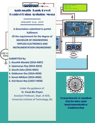
- 1. 1 Automatic Tank Level Control Using Arduino Mega JANUARY 2nd, 2020 A dissertation submitted in partial fulfilment Of the requirement for the degree of BACHELOR OF ENGINEERING ‘APPLIED ELECTRONICS AND INSTRUMENTATION ENGINEERING’ SUBMITTED By: 1. Koushik Mandal (2016-4007) 2. Upamanyu Ray (2016-4023) 3. Souvik Saha (2016-4025) 4. Debkumar Das (2016-4030) 5. Kunal Adhikari (2016-4036) 6. Asit Baran Roy (L2017-4058) Under the guidance of: Er. Faruk Bin Poyen Assistant Professor, Dept. of AEIE, University Institute of Technology, BU Department of Applied Electronics and Instrumentation Engineering
- 2. 2 ACKNOWLEDGEMENT It’s a great privilege for us to express our profound and sincere gratitude to our revered professors of Department of Applied Electronics & Instrumentation Engineering, University Institute of Technology, University of Burdwan, for all valuable guidance, suggestions, and their constant rebukes and commendations, throughout our course of study. This group also thanks our project mentor, Er. Faruk Bin Poyen who has been a constant inspiration to us young aspiring engineers, without whom this project would have been impossible to complete in time.
- 3. 3 UNIVERSITY INSTITUTE OF TECHNOLOGY BURDWAN UNIVERSITY (Department of Applied Electronics and Instrumentation Engineering (AEIE)) CERTIFICATE OF APPROVAL This is to certify that the work embodied in this project entitled “Automatic Tank Level Control using Arduino Mega” submitted by Mr. Koushik Mandal, Mr. Upamanyu Ray, Mr. Souvik Saha, Mr. Debkumar Das, Mr. Kunal Adhikari and Mr. Asit Baran Roy in partial fulfilment for the award of the degree of Bachelor of Engineering in Applied Electronics and Instrumentation Engineering at University Institute of Technology, The University of Burdwan, is the record of the dedicated exertion of the students which has been carried out under my supervision. The work undertaken deemed suitable as an Under Graduate project of the trade AEIE. I hereby forward this dissertation. Date: 2nd January, 2020 Place: Burdwan ______________________ Er. Faruk Bin Poyen Project Guide Assistant Professor, Dept. of AEIE University Institute of Technology University of Burdwan
- 4. 4 UNIVERSITY INSTITUTE OF TECHNOLOGY BURDWAN UNIVERSITY (Department of Applied Electronics and Instrumentation Engineering (AEIE)) CERTIFICATE This is to certify that the project entitled “Automatic Tank Level Control using Arduino Mega” has been submitted by Mr. Koushik Mandal, Mr. Upamanyu Ray, Mr. Souvik Saha, Mr. Debkumar Das, Mr. Kunal Adhikari and Mr. Asit Baran Roy, under my supervision during the year 2019-20 in partial fulfilment requirement for “Bachelor of Engineering” degree in “Applied Electronics & Instrumentation Engineering”, which is a product of their smart work and dedication, and may be treated as a commendable and appreciable job. ____________________ ____________________ Project Guide: Er. Faruk Bin Poyen Dr. Apurba Kr. Ghosh Assistant Professor, Dept. of AEIE H.O.D, Dept. of AEIE, UIT, BU Date: Date:
- 5. 5 CONTENTS 1. LIST OF COMPONENTS 2. (Chapter i) ABSTRACT 3. (Chapter ii) MOTIVATION FOR THE PROJECT 4. (Chapter iii) INTRODUCTION 5. (Chapter iv) OBJECTIVES OF THE PROJECT 6. (Chapter v) PROJECT PARAMETERS 7. (Chapter vi) LOGIC AND ARDUINO DEVELOPMENT BOARD PROGRAM 8. (Chapter (vii) BLOCK DIAGRAM OF THE SYSTEM 9. (Chapter viii) CIRCUIT DIAGRAM 10. (Chapter ix) SNAPSHOTS 11. (Chapter x) CONCLUSION 12. (Chapter xi) FUTURE WORK 13. (Chapter xii) REFERENCES
- 6. 6 LIST OF COMPONENTS Sl. No Component Quantity Model No. Maker’s Name 1 Arduino Mega 16V-TF 355E3F ATMEL 2 US Sensor HC-SR04 - 3 LCD Display and Module RG2004A PCF8574T MH 4 Relay Module JQC3F HONG WEI
- 7. 7 5 Pump Motor Elegant ZIGMA 6 Sump - - 7 Tank - - 8 Water Pipe - - 9 Connecting Wires - -
- 8. 8 10 Jumper Wires - - 11 Breadboard - -
- 9. 9 CHAPTER I ABSTRACT Water is the most important Nature’s gift to mankind. Without water there is no life, especially now that fresh water is endangered. So, water management should reduce its wastage. As a first step, this controller will automatically switch ON and OFF the domestic water pump system depending on the water tank and underground sump levels (to prevent dry run of pump). In this paperwork an effort is made to design a cost-effective circuit and complete system using Arduino and Ultrasonic transducers, to be used in water level indication. It will control the storage level of water in a tank through SPST relay to provide water thoroughly, without any wastage of water or power. Keywords: Water, Management, Pump, Arduino, Ultrasonic, Transducer, Relay
- 10. 10 CHAPTER II MOTIVATION FOR THE PROJECT Water is the most important Nature’s gift to the mankind. Without Water there is no life. One might think everybody understands its importance, especially where water is not easily available, but it’s not always so. In many households and offices, even in industries it is seen that water spillage is very common, and tanks which need maintenance are not bothered about (it has no direct connection to the project but it highlights the lacklustre attitude of humans that has a direct connection to every sort of wastage). On 19th June, 2019 Chennai, the 6th largest city ran out of water completely (a woman was stabbed due to one of many conflicts over water). On the other hand, many times during emergencies and inside bathrooms, water supply suddenly stops, leaving us in a mess. Still, as a generation we are careless and apathetic towards water, at large. As a direct result, Automatic water level monitoring came into existence because of gross error and inconsistence that is associated with manually operated water pumping machine. This is because it takes time for the individual who is manually operating the water pump to turn it off and this may cause water spillage because many times he may not even know whether the tank is full or not; and at times the individual might not know the water level until the tank is completely empty. This problem motivated us to the development of an automatic water level control. On research, other reasons found for the requirement of this system are: 1. to prepare for future droughts and rising agricultural demands. 2. to guard against rising costs and potential conflicts 3. to preserve the environment 4. to strengthen communities 5. to preserve enough water for recreational purposes.
- 11. 11 CHAPTER III INTRODUCTION Manual switching on of pump when taps go dry and switching off when the overhead tank overflows is the general approach towards water tank storage in general. This results in the unnecessary wastage and sometimes non- availability of both water and energy which are increasingly valuable assets of the world as of now. “Automatic Tank Level Control using Arduino Mega” is a project that aims at control of the level of an overhead tank, according to available water level of the storage tank and underground. The water level must be controlled at these two points. This water level control system controls, monitors and maintains the water level in the overhead tank and ensures the continuous flow of water round the clock whenever deemed proper by conditions set by the user, without the stress of going to switch the pump on or off thereby saving time, energy, water, and prevent the pump from overworking. The system has an automatic pumping system attached to it so as to refill the tank once the water is below a certain minimum sump threshold and above a certain minimum tank threshold, when measured from the top. An AC pump is used for the same. The control logic is independently defined according to the sump depth and tank height respectively (both manually measured).
- 12. 12 The control action is performed by interfacing level measuring sensors and SPST relay to Arduino Mega by various jumper wires, and displaying the output on a Liquid Crystal Display. Similar liquid level control systems are widely used in monitoring of liquid levels in small to large scale reservoirs, silos, etc., especially due to its simple control logic coupled with low cost (cost of this project was <₹2000).
- 13. 13 CHAPTER IV OBJECTIVES OF THE PROJECT The goal or objectives of which the designed device is expected to accomplish is to build an automatic water level control system. In this project sensors are placed at both reservoir and overhead tank with the aid of level measurement sensors, and the control board monitors the level of the liquid at any particular point in time, some of the objectives are: to design an automatic water monitoring system to incorporate an interactive medium between the end user and the machine to prevent over labour of the pumping machine and prevent it from burning out to avoid wastage of water since the demand of electricity is very high, automatic water level control saves energy, and time
- 14. 14 CHAPTER V PROJECT PARAMETERS 1. ARDUINO MEGA 2560REV3 Arduino Boards have revitalized the automation industry with their easy to use platform where everyone with little or no technical background can get started with learning some basic skills to program and run the board. The Arduino Mega 2560 is a microcontroller board based on the ATmega2560. It has 54 digital input/output pins (of which 15 can be used as PWM outputs), 16 analog inputs, 4 UARTs (hardware serial ports), a 16 MHz crystal oscillator, a USB connection, a power jack, an ICSP header, and a reset button. It contains everything needed to support the microcontroller; simply connect it to a computer with a USB cable or power it with an AC-to-DC adapter or battery to get started. The Mega 2560 board is compatible with most shields designed for the Uno. It is as open source platform means the board and the software are readily available. There are three ways to power the board. You can either use a USB cable to power the board and transfer code to the board or you can power it up using Vin of the board or through Power jack or batter. Last two sources to power the board are required once you already built and compile code into the board through USB cable. Technical Specifications: Microcontroller: ATmega2560 Operating Voltage: 5V Input Voltage (recommended): 7-12V Input Voltage (limit): 6-20V Digital I/O Pins: 54 (15 provide PWM output) Analog Input Pins: 16 DC Current per I/O Pin: 20 mA DC Current for 3.3V Pin: 50 mA
- 15. 15 Flash Memory: 256 KB (8 KB used by bootloader) SRAM: 8 KB EEPROM: 4 KB Clock Speed: 16 MHz LED_BUILTIN: 13 Length: 101.52 mm Width: 53.3 mm Weight: 37 g Pin Specifications: 5V & 3.3V: This pin is used to provide output regulated voltage around 5V. This regulated power supply powers up the controller and other components on the board. It can be obtained from Vin of the board or USB cable or another regulated 5V voltage supply. While another voltage regulation is provided by 3.3V pin. Maximum power it can draw is 50mA. GND: There are 5 ground pins available on the board which makes it useful when more than one ground pins are required for the project. Reset: This pin is used to reset the board. Setting this pin to LOW will reset the board. Vin: It is the input voltage supplied to the board which ranges from 7V to 20V. The voltage provided by the power jack can be accessed through this pin. However, the output voltage through this pin to the board will be automatically set up to 5V. Serial Communication: RXD and TXD are the serial pins used to transmit and receive serial data i.e. Rx represents the transmission of data while Tx used to receive data. There are four combinations of these serial pins are used where Serial 0 contains RX(0) and TX(1), Serial 1 contains TX(18) and RX(19), Serial 2 contains TX(16) and RX(17), and Serial 3 contains TX(14) and RX(15).
- 16. 16 External Interrupts: Six pins are used for creating external interrupts i.e. interrupt 0(0), interrupt 1(3), interrupt 2(21), interrupt 3(20), interrupt 4(19), interrupt 5(18). These pins produce interrupts by a number of ways i.e. providing LOW value, rising or falling edge or changing value to the interrupt pins. LED: This board comes with built-in LED connected to digital pin 13. HIGH value at this pin will turn the LED on and LOW value will turn it off. This gives you the change of nursing your programming skills in real time. AREF: AREF stands for Analog Reference Voltage which is a reference voltage for analog inputs. Analog Pins: There are 16 analog pins incorporated on the board labelled as A0 to A15. It is important to note that all these analog pins can be used as digital I/O pins. Each analog pin comes with 10-bit resolution. These pins can measure from ground to 5V. However, the upper value can be changed using AREF and analogReference() function. I2C: Two pins 20 and 21 support I2C communication where 20 represents SDA (Serial Data Line mainly used for holding the data) and 21 represents SCL(Serial Clock Line mainly used for providing data synchronization between the devices) SPI Communication: SPI stands for Serial Peripheral Interface used for the transmission of data between the controller and other peripherals components. Four pins i.e. 50 (MISO), 51 (MOSI), 52 (SCK), 53 (SS) are used for SPI communication.
- 17. 17 Programming: Arduino Mega 2560 can be programmed using Arduino Software called IDE which supports C programming. The code you make on the software is called sketch which is burned in the software and then transferred to the board through USB cable. This board comes with a built-in bootloader which rules out the usage of an external burner for burning the code into the board. The bootloader communicates using STK500 protocol. Once you compile and burn the program on the board, you can unplug the USB cable which eventually removes the power from the board. When you intend to incorporate the board into your project, you can power it up using power jack or Vin of the board. Applications: Developing 3D printer Controlling and handling more than one motors Interfacing of number of sensors Sensing and detecting temperature Multi-level liquid detection projects Home automation and security systems Embedded Systems IoT applications Parallel programming and Multitasking 2. ULTRASONIC SENSOR An ultrasonic sensor is an instrument that measures the distance to an object using ultrasonic sound waves. It sends and receives ultrasonic pulses that relay back information about an object’s proximity. High-frequency sound waves reflect from boundaries to produce distinct echo patterns. Working Principle:
- 18. 18 Ultrasonic sound vibrates at a frequency above the range of human hearing. Transducers are the microphones used to receive and send the ultrasonic sound. Our ultrasonic sensors, like many others, use a single transducer to send a pulse and to receive the echo. The sensor determines the distance to a target by measuring time lapses between the sending and receiving of the ultrasonic pulse. HC-SR04 Ultrasonic (US) sensor is a 4 pin module, whose pin names are Vcc, Trigger, Echo and Ground respectively. This sensor is a very popular sensor used in many applications where measuring distance or sensing objects are required. The module has two eyes like projects in the front which forms the Ultrasonic transmitter and Receiver. The sensor works with the simple high school formula of Distance = Speed × Time The Ultrasonic transmitter transmits an ultrasonic wave, this wave travels in air and when it gets objected by any material it gets reflected back toward the sensor this reflected wave is observed by the Ultrasonic receiver module. Now, to calculate the distance using the above formulae, we should know the Speed and time. Since we are using the Ultrasonic wave we know the universal speed of US wave at room conditions which is 340m/s. So using the time taken by the wave to reflect back and be detected by the receiver one can easily calculate the distance of the object from the point of observation. Specifications: No. of pins: 4 (5V Supply, Trigger Pulse Input, Echo Pulse Output, Ground) Operating voltage: +5V Theoretical Measuring Distance: 2cm to 450cm Practical Measuring Distance: 2cm to 80cm
- 19. 19 Accuracy: 3mm Measuring angle covered: <15° Operating Current: <15mA Operating Frequency: 40Hz Trigger Input Signal: 10uS TTL pulse Echo Output Signal: Input TTL lever signal and the range in proportion Dimension: 45*20*15mm Applications: Used to avoid and detect obstacles with robots like biped robot, obstacle avoider robot, path finding robot etc. Used to measure the distance within a wide range of 2.5cm to 400cm Can be used to map the objects surrounding the sensor by rotating it Depth of certain places like wells, pits etc. can be measured since the waves can penetrate through water 3. LIQUID CRYSTAL DISPLAY (I2C): A liquid-crystal display (LCD) is a flat-panel display or other electronically modulated optical device that uses the light-modulating properties of liquid crystals. Liquid crystals do not emit light directly, instead using a backlight or reflector to produce images in colour or monochrome. LCDs are available to display arbitrary images (as in a general-purpose computer display) or fixed images with low information content, which can be displayed or hidden, such as preset words, digits, and seven-segment displays, as in a digital clock. They use the same basic technology, except that arbitrary images are made up of a large number of small pixels, while other displays have larger elements. LCDs can either be normally on (positive) or off (negative), depending on the polarizer arrangement. For example, a character
- 20. 20 positive LCD with a backlight will have black lettering on a background that is the colour of the backlight, and a character Negative LCD will have a black background with the letters being of the same colour as the backlight. Small LCD screens are common in portable consumer devices such as digital cameras, watches, calculators, and mobile telephones, including smart phones. LCD screens are also used on consumer electronics products such as DVD players, video game devices and clocks. LCD screens have replaced heavy, bulky cathode ray tube (CRT) displays in nearly all applications. The LCD screen is more energy-efficient and can be disposed of more safely than a CRT can. Its low electrical power consumption enables it to be used in battery-powered electronic equipment more efficiently than CRTs can be. By 2008, annual sales of televisions with LCD screens exceeded sales of CRT units worldwide, and the CRT became obsolete for most purposes. 4. RELAY MODULE: It is a 4-channel SPST Relay module that consists of 4 SPST Relays capable of both NO and NC connections. The Relay output state is shown by a red LED. It finds applications in any sort of simple switching. It has the following terminals: COIL A - This is one end of the coil. COIL B- This is the other end of the coil. These are the terminals where we apply voltage to in order to give power to the coils (which then will close the
- 21. 21 switch). The polarity does not matter. One side gets positive voltage and the other side gets negative voltage. NO - This is Normally Open switch. This is the terminal where the device is connected that we want the relay to activate when the relay is powered. The device connected to NO terminal will be deactivated when the relay has no power and will turn on when the relay receives power. We will use this terminal for powering the pump. NC - This is the Normally Closed Switch. This is the terminal where we connect the device that we want powered when the relay receives no power. The device connected to NC will be active when the relay has no power and will deactivate when the relay receives power. COM - This is the common terminal of the relay. When the relay is powered and the switch is closed, COM and NO will be shorted. If the relay isn't powered and the switch is open, COM and NC get shorted. Specifications: 4-Channel Relay interface board, and each one needs 15-20mA Driver Current Both controlled by 12V and 5V input Voltage Equipped with high-current relay, AC250V 10A ; DC30V 10A Standard interface that can be controlled directly by microcontroller (Arduino , 8051, AVR, PIC, DSP, ARM, ARM, MSP430, TTL logic active low Dimension: 50mm*70mm*15mm Opto-isolated inputs Indication LED’s for Relay output status.
- 22. 22 5. PUMP MOTOR: The pump motor for the project level working is taken as a submersible pump, made by the company Zigma (picture attached). The shell is made of high quality stronger ABS. It is water proof and has good performance of insulation. It is of compact size, easy to install and has multiple usage. It is easy to clean and runs on supply power (230VAC, 50Hz). Specifications: Voltage supply: 165-230V/50Hz Power: 19W Max. head: 1.9m Output: 1100Lph Applications: Cooler, aquarium, garden and other small to medium household/office applications. 6. JUMPER WIRES: A jump wire (also known as jumper wire, or jumper) is an electrical wire, or group of them in a cable, with a connector or pin at each end (or sometimes without them – simply "tinned"), which is normally used to interconnect the components of a
- 23. 23 breadboard or other prototype or test circuit, internally or with other equipment or components, without soldering. Individual jump wires are fitted by inserting their "end connectors" into the slots provided in a breadboard, the header connector of a circuit board, or a piece of test equipment. There are different types of jumper wires. Some have the same type of electrical connector at both ends, while others have different connectors. Some common connectors are: Solid tips – are used to connect on/with a breadboard or female header connector. The arrangement of the elements and ease of insertion on a breadboard allows increasing the mounting density of both components and jump wires without fear of short-circuits. The jump wires vary in size and colour to distinguish the different working signals. Crocodile clips – are used, among other applications, to temporarily bridge sensors, buttons and other elements of prototypes with components or equipment that have arbitrary connectors, wires, screw terminals, etc. Banana connectors – are commonly used on test equipment for DC and low- frequency AC signals. Registered jack (RJnn) – are commonly used in telephone (RJ11) and computer networking (RJ45). RCA connectors – are often used for audio, low-resolution composite video signals, or other low-frequency applications requiring a shielded cable. RF connectors – are used to carry radio frequency signals between circuits, test equipment, and antennas.
- 24. 24 7. BREADBOARD: A breadboard is a construction base for prototyping of electronics. Originally the word referred to a literal bread board, a polished piece of wood used for slicing bread. Nowadays the term "breadboard" is commonly used to refer to these because the solder less breadboard does not require soldering, it is reusable. This makes it easy to use for creating temporary prototypes and experimenting with circuit design. For this reason, solder less breadboards are also popular with students and in technological education. Older breadboard types did not have this property. A "full size" terminal breadboard strip typically consists of around 56 to 65 rows of connectors, each row containing the above-mentioned two sets of connected clips. Together with bus strips on each side this makes up a typical 784 to 910 tie point solder less breadboard. "Small size" strips typically come with around 30 rows. Miniature solder less breadboards as small as 17 rows can be found, but these are only suitable for small and simple designs. Due to relatively large parasitic capacitance compared to a properly laid out PCB (approx. 2pF between adjacent contact columns), high inductance of some connections and a relatively high and not very reproducible contact resistance, solder less breadboards are limited to operation at relatively low frequencies, usually less than 10 MHz, depending on the nature of the circuit. The relatively high contact resistance can already be a problem for some DC and very low frequency circuits. Solder less breadboards are further limited by their voltage and current ratings.
- 25. 25 CHAPTER VI LOGIC AND ARDUINO DEVELOPMENT BOARD PROGRAM DISTANCE1 (cm) DISTANCE2 (cm) PUMP STATUS LOW (>=23) LOW (>=15) LOW (OFF) LOW (>=23) HIGH (<=3) LOW (OFF) HIGH (<23) LOW (>=15) HIGH (ON) HIGH (<23) HIGH (<=3) LOW (OFF) #include <LiquidCrystal_I2C.h> #define triggertank 9 #define echotank 10 //tank #define triggersump 11 #define echosump 12 //sump LiquidCrystal_I2C lcd(0x27,20,4); float time1=0.00, distance1=0.00, time2=0.00, distance2=0.00, tankp=0.00; float low=3; const int MOTOR = 7; String buf; void setup() { Serial.begin(9600); pinMode(triggertank,OUTPUT);
- 26. 26 pinMode(triggersump,OUTPUT); pinMode(echosump,INPUT); pinMode(echotank,INPUT); pinMode(MOTOR, OUTPUT); lcd.init(); lcd.backlight(); lcd.setCursor(0,0); lcd.print("WATER LEVEL CTRL SYS"); lcd.setCursor(0,1); delay(1000); lcd.print(" Dept of AEIE "); delay(3000); } void loop() { lcd.clear(); digitalWrite(triggersump,LOW); delayMicroseconds(2); digitalWrite(triggersump,HIGH); delayMicroseconds(10); digitalWrite(triggersump,LOW); delayMicroseconds(2); time1=pulseIn(echosump,HIGH); distance1=time1*0.034/2; //SUMPSTUFF digitalWrite(triggertank,LOW); delayMicroseconds(2);
- 27. 27 digitalWrite(triggertank,HIGH); delayMicroseconds(10); digitalWrite(triggertank,LOW); delayMicroseconds(2); time2=pulseIn(echotank,HIGH); distance2=time2*0.034/2; //TANKSTUFF Serial.print("Sump: "); Serial.println(distance1); Serial.print("Tank: "); Serial.println(distance2); if(distance1>=23) { digitalWrite(MOTOR, HIGH); lcd.setCursor(1,0); lcd.print("SUMP : EMPTY"); lcd.setCursor(1,1); lcd.print("PUMP : OFF"); delay(500); }//00_01 else if(distance1<23) { lcd.setCursor(1,0); lcd.print("SUMP : NOT EMPTY"); if(distance2<low) { digitalWrite(MOTOR, HIGH);
- 28. 28 lcd.setCursor(1,1); lcd.print("PUMP : OFF"); low=15.00; delay(100); }//11 else if(distance2>=low) { digitalWrite(MOTOR, LOW); lcd.setCursor(1,1); lcd.print("PUMP : ON"); delay(100); }//10 } tankp=(1-distance2/9.52)*100; buf = String(tankp, 2); lcd.setCursor(1,2); lcd.print("TANK LEVEL: "); lcd.print(buf); lcd.print("%"); delay(1200); }//ENDOFPROGRAM
- 29. 29 CHAPTER VII BLOCK DIAGRAM OF THE SYSTEM
- 32. 32 CHAPTER X CONCLUSION With the help of the code in the Arduino and interfacing with the sensors and LCD, we have successfully assembled a circuit which allows the pump to fill the water tank within upper and lower heights, 15 and 3 cm respectively, depending upon water presence in sump. As an added practical application, we provided a tap to remove the water, which signifies the usage of water through taps and showers in household and offices. The circuitry works perfectly and has been tested various times under varying conditions and sump/tanks.
- 33. 33 CHAPTER XI FUTURE WORK The water level controller designed in this project can be used to control water flow, as per normally occurring logic (provided earlier). We have already taken care that the pump will not perform dry run and the tank will start filling again only after it reaches a low height. In future work, we think of considering the ambient temperature of the surroundings and temperature of water, to set the window of upper and lower limits, and use a geyser in case the ambient is cold enough for a warm, cozy bath. Also, the rate of water filling the sump must always be equal to or greater than the rate of water output. To make this happen we could use a speed regulator.
- 34. 34 CHAPTER XII REFERENCES 1. Store.arduino.cc. (2020). Arduino Mega 2560 Rev3 | Arduino Official Store. [online] Available at: https://store.arduino.cc/usa/mega-2560-r3 2. ISLAM (2020). Project report. [online] Slideshare.net. Available at: https://www.slideshare.net/MDJAHIDULISLAM6/project-report- 64330060 3. A Course In Electrical And Electronic Measurements And Instrumentation A. K. Sawhney 4. Katsuhiko Ogata, “Modern control engineering”, Pearson education 2011, 5th edition 5. Google.co.in. (2020). Google Images. [online] Available at: https://www.google.co.in/imghp?hl=en&tab=wi&authuser=0&ogbl 6. Maker Pro. (2020). HC-SR04 Datasheet | Ultrasonic Proximity Sensor | Custom. [online] Available at: https://maker.pro/custom/tutorial/hc-sr04-ultrasonic-proximity- sensor-datasheet-highlights 7. Elecfreaks.com. (2020). 4 Channel 12V Relay Module BK_RL4_01. [online] Available at: https://www.elecfreaks.com/estore/4- channel-12v-relay-module-bk-rl4-01.html 8. Aqeel, A. (2020). Introduction to Arduino Mega 2560 - The Engineering Projects. [online] The Engineering Projects. Available at: https://www.theengineeringprojects.com/2018/06/introduction-to- arduino-mega-2560.html 9. Non Resident Indians Online. (2020). India's 100 Biggest Cities, Largest Cities in India. [online] Available at: https://www.nriol.com/india-statistics/biggest-cities-india.asp 10. En.wikipedia.org. (2020). 2019 Chennai water crisis. [online] Available at: https://en.wikipedia.org/wiki/2019_Chennai_water_crisis 11. GitHub. (2020). johnrickman/LiquidCrystal_I2C. [online] Available at: https://github.com/johnrickman/LiquidCrystal_I2C/blob/master/Li quidCrystal_I2C.cpp [Accessed 1 Jan. 2020].