Noriyuki Aibe, "High Efficiency Connection Method on Electric Signal Lines between Modular Circuit Boards", ICDF2016, D04, Tokyo, Japan, 3-5 Mar. 2016.
Semelhante a Noriyuki Aibe, "High Efficiency Connection Method on Electric Signal Lines between Modular Circuit Boards", ICDF2016, D04, Tokyo, Japan, 3-5 Mar. 2016.
Semelhante a Noriyuki Aibe, "High Efficiency Connection Method on Electric Signal Lines between Modular Circuit Boards", ICDF2016, D04, Tokyo, Japan, 3-5 Mar. 2016. (20)
Noriyuki Aibe, "High Efficiency Connection Method on Electric Signal Lines between Modular Circuit Boards", ICDF2016, D04, Tokyo, Japan, 3-5 Mar. 2016.
1. ICDF: International Conference on Digital Fabrication 2016, D04, Tokyo, Japan, 3-5 Mar. 2016.
High Efficiency Connection Method on Electric Signal Lines
between Modular Circuit Boards
Noriyuki Aibe, SUSUBOX Co., Ltd., susu@susubox.com
INTRODUCTION
The “Bit-shift connection” is a novel connection method for electric signal lines between
modular circuit boards. This method is especially useful for FPGA and CPLD prototyping
modular boards. General modular circuit boards such as an Arduino and its shield boards
use a BUS connection. However it has critical problem that many boards are not able to
use together. The reason why it is not able to use together is pin conflict. Ideally all
connection between MPU, FPGA, CPLD and I/O interface should be independently.
However it is not realistic, because it is required vast area for electric connection lines
and huge number of pins of connectors. So there are some research that build more high
speed line on PCB*1
, or connect without wires*2
. The “Bit-shift connection” solves these
problems on normal PCB by using a simple method of independent connection on limited
board area and number of pins. So it is easy to implement.
MODULAR BOARD
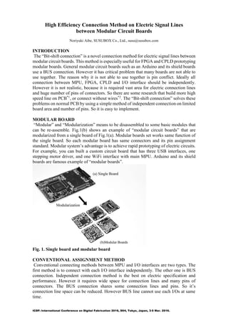
“Modular” and “Modularization” means to be disassembled to some basic modules that
can be re-assemble. Fig.1(b) shows an example of “modular circuit boards” that are
modularized from a single board of Fig.1(a). Modular boards set works same function of
the single board. So each modular board has same connectors and its pin assignment
standard. Modular system’s advantage is to achieve rapid prototyping of electric circuits.
For example, you can built a custom circuit board that has three USB interfaces, one
stepping motor driver, and one WiFi interface with main MPU. Arduino and its shield
boards are famous example of “modular boards”.
Fig. 1. Single board and modular board
CONVENTIONAL ASSIGNMENT METHOD
Conventional connecting methods between MPU and I/O interfaces are two types. The
first method is to connect with each I/O interface independently. The other one is BUS
connection. Independent connection method is the best on electric specification and
performance. However it requires wide space for connection lines and many pins of
connectors. The BUS connection shares some connection lines and pins. So it’s
connection line space can be reduced. However BUS line cannot use each I/Os at same
time.
2. ICDF: International Conference on Digital Fabrication 2016, D04, Tokyo, Japan, 3-5 Mar. 2016.
Bus line connection
The BUS line shares some bits lines. So it called “n bits bus” such as 8 bit bus, 16 bit
bus. The BUS connection is the least number of connection lines. Fig.2 shows an example
of 3 bits bus lines with four modular boards. The left side board “Module A” is a MPU
board. The other boards “Module B” to “Module D” are I/O interface board such as a
switch input, a LED output, and an UART interface. Each board has same connectors of
CN1 and CN2. CN1 is able to connect to CN2. Each numbers inside of the frame shows
pin numbers.
The critical problem of BUS connection is each function is not able to work at same time
on shared lines. On Fig.2, function B and C or function B and D is able to communicate
with MPU at same time. However function C and D is not able to do. So function C and
D works with time-sharing technique. This problem occurred often on Arduino using two
or more shields.
Fig. 2. Bus line connection (ex. Arduino)
Independent connection
Fig.3 shows an example of the independent connection with “star topology”. If you can
use wide area for line space and much number of pins, it is the best connection between
MPU and the other I/O interfaces. In Fig.3, MPU board is centered on the other I/O
interface boards. So each connection line distance between MPU and function parts are
minimum length. Of course, each functions are able to communicate with MPU at same
time. However independent connection requires most wide area. Then star topology’s
structure tends to spread on flat. So the star topology is not useful for embedded
systems.
Fig. 3. Independent connection (Star topology)
3. ICDF: International Conference on Digital Fabrication 2016, D04, Tokyo, Japan, 3-5 Mar. 2016.
On many circuits that are not so fast about under 100 MHz, you can use independent
connection with “line topology” (Fig.4). On Fig.4, function B is assigned to pin 1 of
CN2 and the other lines are sent to next module. Function C is assigned to pin 2 of CN2
on module C and it is connected through the line assigned to pin 2 on module B.
Function D is assigned pin 3 and connected through module B and C. On this
connection method, all modular boards are designed with the “sending lines” and
decided pin assignment from modules which is used together in advance. So some
combination of modules are not able to connect, if it remains many lines and pins. Then
same modules are not able to connect together too.
Fig. 4. Independent connection (Line topology)
PROPOSED METHOD
The “Bit-shift connection” is a solution of these problems. It is one kind of independent
connection. The “sending lines” on Fig.4 re-assigned with bit-shift connection. On Fig.5,
pin 1 is assigned function B on module B. It is same as Fig.4. However pin 2 and 3 on
CN2 is assigned pin 1 and 2 on CN1 of module B. So function C is connected to MPU
with “pin 1” on CN2 of module C. Function D is assigned “pin 1” on CN2 of own module.
On this method, all connection lines are able to use and it is not required to be designed
pin assignment of the relation between each module in advance. You can use same
modules together and possible to use any order of modules. However the pin assignment
of MPU side must be able to replace freely. So it is especially useful for FPGA and CPLD.
Fig.6 shows an example of modular boards using the “Bit-shift connection”. It is able to
stack as long as the number of MPU’s I/O pins allows. All I/O interface modular boards
are possible to change the order too.
Fig. 5. Bit-shift connection
4. ICDF: International Conference on Digital Fabrication 2016, D04, Tokyo, Japan, 3-5 Mar. 2016.
Fig. 6. Modular boards using the Bit-shift connection
On the real application, it requires BUS or daisy chain type connections such as I2C, SPI,
JTAG, clock line, and reset line too. So one of the recommended implementation is to use
both types with dual lines as shown in Fig.6.
CONCLUSIONS
The “Bit-shift connection” is a novel method of independent connection between modular
boards. On this method, all I/O pins of MPU, FPGA, or CPLD are able to use without
leaving. These modules that are designed using this method are possible to use same
module together and possible to change the order. However on this method, the pin
assignment of MPU side must be able to replace freely and it is a little difficult to manage
pin assignment.
REFERENCES
1. Hidefumi Inoue, Moritoshi Yasunaga, Kenji kanazawa, and Noriyuki Aibe,
“Signal Integrity Evaluation of Segmental Transmission Line under Real-world
Application”, Proceedings of 2013 IEEE Electrical Design of Advanced
Packaging & Systems Symposium (EDAPS 2013), pp. 108-111, Nara, Japan,
Dec. 2013.
2. Skjin Kim, "High-Efficiency PCB- and Package-Level Wireless Power
Transfer Interconnection Scheme Using Magnetic Field Resonance Coupling",
IEEE Trans. Packaging and Manuf, Vol. 5, No.7, pp(863-878), 2015.
ACKNOWLEDGEMENT
This research is supported in part by the 2009-2012 Japan Science and Technology
5. ICDF: International Conference on Digital Fabrication 2016, D04, Tokyo, Japan, 3-5 Mar. 2016.
Agency and University of Tsukuba.