SlideShare uma empresa Scribd logo
1 de 275
Baixar para ler offline
U340E AUTOMATIC TRANSAXLE – AUTOMATIC TRANSAXLE SYSTEM AX–1
AX
AUTOMATIC TRANSAXLE
SYSTEM
PRECAUTION
NOTICE:
• Perform the RESET MEMORY (AT initialization) when
replacing the automatic transaxle assembly, engine
assembly or ECM (See page AX-14).
• Perform the REGISTRATION (VIN registration) when
replacing the ECM (See page ES-13).
HINT:
The RESET MEMORY cannot be completed by only
disconnecting the battery cable.
CAUTION:
When using compressed air, always aim away from
yourself to prevent Automatic Transmission Fluid (ATF)
or kerosene from spraying on your face.
NOTICE:
• The automatic transaxle is composed of high
precision parts which need careful inspection before
reassembly. Even a small nick could cause fluid
leakage or affect the performance. The instructions
here are organized so that you work on only one
component group at a time. This will help avoid
confusion caused by similar-looking parts of different
sub-assemblies being on your workbench at the same
time. The component groups are inspected and
repaired from the converter housing side. As far as
possible, complete the inspection, repair and
reassembly before proceeding to the next component
group. If a defect is found in a certain component
group during reassembly, inspect and repair that
group immediately. If a component group cannot be
assembled because some parts are on order, be sure
to keep all parts of the group in a separate container
while proceeding with disassembly, inspection, repair
and reassembly of other component groups.
• When changing the automatic transmission fluid, use
only "Toyota Genuine ATF WS" (ATF JWS3324 or
NWS9638).
• All disassembled parts should be washed clean and
any fluid passages and holes should be blown
through with compressed air.
• Dry all parts with compressed air. Never use a shop
rag or a piece of cloth to dry them.
• Only recommended ATF or kerosene should be used
for cleaning.
• After cleaning, the parts should be arranged in the
correct order for efficient inspection, repair, and
reassembly.
• When disassembling a valve body, be sure to match
each valve with the corresponding spring.
AX–2 U340E AUTOMATIC TRANSAXLE – AUTOMATIC TRANSAXLE SYSTEM
AX
• New brake and clutch discs that are to be used for
replacement must be soaked in ATF for at least 15
minutes before reassembly.
• All oil seal rings, clutch discs, clutch plates, rotating
parts, and sliding surfaces should be coated with ATF
prior to reassembly.
• All gaskets and rubber O-rings should be replaced
with new ones.
• Do not apply adhesive cements to gaskets or similar
parts.
• Make sure that the ends of snap rings are not aligned
with any cutouts and are installed in the grooves
correctly.
• When replacing a worn bushing, the sub-assembly
containing the bushing must also be replaced.
• Check thrust bearings and races for wear and
damage. Replace them as necessary.
• When working with FIPG material, you must observe
the following:
– Using a razor blade and a gasket scraper, remove
all the old packing (FIPG) material from the gasket
surface.
– Clean both sealing surfaces with a non-residue
solvent.
– Parts must be reassembled within 10 minutes of
application. Otherwise, the packing (FIPG) material
must be removed and reapplied.
U340E AUTOMATIC TRANSAXLE – AUTOMATIC TRANSAXLE SYSTEM AX–3
AX
DEFINITION OF TERMS
Term Definition
Monitor description Description of what the ECM monitors and how it detects malfunctions (monitoring purpose and its details).
Related DTCs
A group of diagnostic trouble codes that are output by the ECM based on the same malfunction detection
logic.
Typical enabling conditions
Preconditions that allow the ECM to detect malfunctions.
With all preconditions satisfied, the ECM sets the DTC when the monitored value(s) exceeds the
malfunction threshold(s).
Sequence of operation
The priority order that is applied to monitoring, if multiple sensors and components are used to detect the
malfunction.
While one sensor is being monitored, the next sensor or component is not monitored until the current
monitoring is concluded.
Required sensor/components The sensors and components that are used by the ECM to detect malfunctions.
Frequency of operation
The number of times that the ECM checks for malfunctions per driving cycle.
"Once per driving cycle" means that the ECM detects malfunctions only one time during a single driving
cycle.
"Continuous" means that the ECM detects malfunctions every time the enabling conditions are met.
Duration
The minimum time that the ECM must sense a continuous deviation in the monitored value(s) before
setting a DTC. This timing begins when the typical enabling conditions are met.
Malfunction thresholds Beyond this value, the ECM concludes that there is a malfunction and sets a DTC.
MIL operation
MIL illumination timing after a defect is detected.
"Immediate" means that the ECM illuminates the MIL the instant the ECM determines that there is a
malfunction.
"2 driving cycle" means that the ECM illuminates the MIL if the same malfunction is detected again in the
next driving cycle.
Component operating range
Normal operating ranges of sensors and solenoids under normal driving conditions.
Use these ranges as references.
They cannot be used to judge if a sensor or solenoid is defective or not.
AX–4 U340E AUTOMATIC TRANSAXLE – AUTOMATIC TRANSAXLE SYSTEM
AX
PARTS LOCATION
PARK / NEUTRAL
POSITION SWITCH
TRANSMISSION REVOLUTION
SENSOR (SPEED SENSOR (NT))
VEHICLE SPEED SENSOR
STOP LIGHT SWITCH
COMBINATION METER
- MIL (MALFUNCTION INDICATOR LAMP)
DLC3
(DATA LINK CONNECTOR 3)
ECM
SHIFT SOLENOID VALVE S2
SHIFT SOLENOID VALVE S1
SHIFT SOLENOID VALVE ST
SHIFT SOLENOID VALVE SLU
SHIFT SOLENOID VALVE SLT
SHIFT LOCK CONTROL ECU
TRANSMISSION WIRE
(ATF TEMPERATURE SENSOR)
C130143E01
U340E AUTOMATIC TRANSAXLE – AUTOMATIC TRANSAXLE SYSTEM AX–5
AX
SYSTEM DIAGRAM
The configuration of the electronic control system in the
U340E automatic transaxle is as shown in the following chart.
To IG2 Relay
To Ignition Switch
Park/Neutral Position Switch
ST
Starter
ETCS
ST
EFI
To C/OPN Relay
MAIN
Battery
EFI
IGN
ECM
IGSW
STAR
STA
+BM
BATT
+B
+B2
MREL
ST1-
STP
SLU+
SLU-
SLT+
SLT-
S1
S2
ST
THO1
ETHO
Stop Light Switch
Stop Light
STOP
Electronically Controlled Transmission
Solenoid
Shift Solenoid Valve SLU
Shift Solenoid Valve SLT
Shift Solenoid Valve S1
Shift Solenoid Valve S2
Shift Solenoid Valve ST
ATF Temperature Sensor
ODMS
P
R
N
D
2
L
Shift Lock Control ECU
To Gauge Fuse
Park/Neutral Position Switch
E1
E01
E02
C130145E01
AX–6 U340E AUTOMATIC TRANSAXLE – AUTOMATIC TRANSAXLE SYSTEM
AX
W
SPD
TACH
TC
CANH
CANL
NT+
NT-
To MET Fuse
Combination Meter
DLC3
To CAN BUS
Transmission Revolution Sensor
(Speed Sensor NT)
To ECU-IG
Fuse
Vehicle Speed Sensor
C130144E01
U340E AUTOMATIC TRANSAXLE – AUTOMATIC TRANSAXLE SYSTEM AX–7
AX
SYSTEM DESCRIPTION
1. SYSTEM DESCRIPTION
(a) The ECT (Electronic Controlled automatic
Transmission/Transaxle) is an automatic
transmission/transaxle that electronically controls
shift timing using the ECM. The ECM detects
electrical signals that indicate engine and driving
conditions, and controls the shift point, based on
driver habits and road conditions. As a result, fuel
efficiency and power transmission/transaxle
performance are improved.
Shift shock has been reduced by controlling the
engine and transmission simultaneously.
In addition, the ECT has features such as the
following:
• Diagnostic function
• Fail-safe function when a malfunction occurs
AX–8 U340E AUTOMATIC TRANSAXLE – AUTOMATIC TRANSAXLE SYSTEM
AX
HOW TO PROCEED WITH
TROUBLESHOOTING
HINT:
• The ECM of this system is connected to the CAN
communication system. Therefore, before starting
troubleshooting, be sure to check that there is no trouble in
the CAN communication system.
• The intelligent tester can be used in steps 3, 4, 6, and 9.
NEXT
NEXT
NEXT
HINT:
(See page AX-25).
NEXT
NEXT
HINT:
(See page AX-26).
NEXT
HINT:
(See page AX-9).
1 Vehicle Brought to Workshop
2 Customer Problem Analysis
3 Connect Intelligent Tester to DLC3
4 Check and Clear DTCs and Freeze Frame Data
5 Visual Inspection
6 Setting Check Mode Diagnosis
7 Problem Symptom Confirmation
Symptom does not occur: Go to step 8
Symptom occurs: Go to step 9
U340E AUTOMATIC TRANSAXLE – AUTOMATIC TRANSAXLE SYSTEM AX–9
AX
HINT:
(See page IN-26).
NEXT
HINT:
(See page AX-25).
HINT:
(See page AX-93, AX-106 and AX-107).
NG
OK
HINT:
(See page AX-11).
NG
OK
HINT:
(See page AX-13).
NG
OK
HINT:
(See page AX-14).
NG
OK
8 Symptom Simulation
9 DTC Check
DTC is not output: Go to step 10
DTC is output: Go to step 17
10 Basic Inspection
Go to step 19
11 Mechanical System Test
Go to step 16
12 Hydraulic Test
Go to step 16
13 Manual Shifting Test
Go to step 15
AX–10 U340E AUTOMATIC TRANSAXLE – AUTOMATIC TRANSAXLE SYSTEM
AX
HINT:
(See page AX-17).
NG
OK
HINT:
(See page AX-17).
NEXT
HINT:
(See page AX-32).
NEXT
NEXT
NEXT
NEXT
14 Problem Symptoms Table Chapter 1
Go to step 18
15 Problem Symptoms Table Chapter 2
16 Part Inspection
Go to step 19
17 DTC Chart
18 Circuit Inspection
19 Repair or Replace
20 Confirmation Test
End
U340E AUTOMATIC TRANSAXLE – AUTOMATIC TRANSAXLE SYSTEM AX–11
AX
ROAD TEST
1. PROBLEM SYMPTOM CONFIRMATION
(a) Based on the result of the customer problem
analysis, try to reproduce the symptoms. If the
problem is that the transaxle does not shift up, shift
down, or the shift point is too high or too low,
conduct the following road test referring to the
automatic shift schedule and simulate the problem
symptoms.
2. PERFORM ROAD TEST
NOTICE:
Perform the test at the ATF (Automatic Transmission
Fluid) temperature 50° to 80 °C (122° to 176 °F) in the
normal operation.
(a) D position test
Shift into the D position, fully depress the
accelerator pedal and check the following points.
(1) Check up-shift operation.
Check that 1st to 2nd, 2nd to 3rd and 3rd to 4th
up-shifts take place, and that the shift points
conform to the automatic shift schedule (See
page SS-19).
HINT:
4th Gear Up-shift Prohibition Control
• Engine coolant temperature is 60 °C (140 °F)
or less.
• ATF temperature is 10 °C (50 °F) or less.
4th Gear Lock-up Prohibition Control
• Brake pedal is depressed.
• Accelerator pedal is released.
• Engine coolant temperature is 60 °C (140 °F)
or less.
• ATF temperature is 10 °C (50 °F) or less.
(2) Check for shift shock and slippage.
Check for shock and slippage when up-shifting
from 1st to 2nd, 2nd to 3rd and 3rd to 4th.
(3) Check for abnormal noises and vibration.
Check for abnormal noise and vibration when
up-shifting from 1st to 2nd, 2nd to 3rd and 3rd to
4th while driving with the shift lever in the D
position, and also check while driving in the lock-
up condition.
HINT:
The cause of abnormal noises and vibration
must be checked very thoroughly as it could also
cause loss of balance in parts, such as the
differential and torque converter.
AX–12 U340E AUTOMATIC TRANSAXLE – AUTOMATIC TRANSAXLE SYSTEM
AX
(4) Check kick-down operation.
Check the possible kick-down vehicle speeds
when the 2nd to 1st, 3rd to 2nd and 4th to 3rd
kick-downs take place while driving with the shift
lever in the D position. Confirm that each takes
place within the applicable vehicle speed range
indicated in the automatic shift schedule (See
page SS-19).
(5) Check for abnormal shock and slippage during
kick-down.
(6) Check the lock-up mechanism.
• Drive in the D position (4th gear) at a
constant speed (lock-up ON) of
approximately 37 mph (60 km/h).
• Lightly depress the accelerator pedal and
check that the engine speed does not change
abruptly.
HINT:
• There is no lock-up function in the 1st, 2nd
and 3rd gears in the D position.
• If there is a sudden increase in engine speed,
lock-up has not occurred.
(b) 3 position test
Shift into the 3 position, fully depress the accelerator
pedal and check the following points:
(1) Check the transmission control switch operation.
While driving in the D position (4th gear), shift
the shift lever into the 3 position, and check that
the 4th to 3rd down-shift takes place.
(2) Check up-shift operation.
Check that the 1st to 2nd and 2nd to 3rd up-
shifts take place, and that the shift points
conform to the automatic shift schedule (See
page SS-19).
HINT:
There is no 3rd to 4th up-shift in the 3 position.
(3) Check engine braking.
While driving in the 3 position and 3rd gear,
release the accelerator pedal and check the
engine braking effect.
(c) 2 position test
Shift into the 2 position and fully depress the
accelerator pedal and check the following points.
(1) Check up-shift operation.
Check that the 1st to 2nd up-shift takes place
and that the shift point conforms to the automatic
shift schedule (See page SS-19).
HINT:
There is no lock-up function in the 2 position.
(2) Check engine braking.
While driving in the 2 position and 2nd gear,
release the accelerator pedal and check the
engine braking effect.
U340E AUTOMATIC TRANSAXLE – AUTOMATIC TRANSAXLE SYSTEM AX–13
AX
(3) Check for abnormal noises during acceleration
and deceleration, and for shock during up-shift
and down-shift.
(d) L position test
Shift into the L position, fully depress the accelerator
pedal and check the following points.
(1) Check that no up-shift takes place.
While driving in the L position, check that there
is no up-shift to 2nd gear.
(2) Check engine braking.
While driving in the L position, release the
accelerator pedal and check the engine braking
effect.
(3) Check for abnormal noises during acceleration
and deceleration.
(e) R position test
Shift into the R position, fully depress the
accelerator pedal and check for slippage.
CAUTION:
Before conducting this test, ensure that the test
area is free from people and obstructions.
(f) P position test
Stop the vehicle on a slope (more than 5°), shift into
the P position and release the parking brake. Check
that the vehicle does not move.
AX–14 U340E AUTOMATIC TRANSAXLE – AUTOMATIC TRANSAXLE SYSTEM
AX
MECHANICAL SYSTEM TESTS
1. STALL SPEED TEST
HINT:
This test is to check the overall performance of the
engine and transaxle by measuring the stall speeds in
the D position.
NOTICE:
• Do not perform the stall speed test for longer than
5 seconds.
• To ensure safety, perform this test in a wide, clear
level area which provides good traction.
• The stall speed test must always be carried out by
pairs of technicians. One technician must watch
the wheels and wheel stoppers from outside the
vehicle to make sure they do not slip, while the
other performs the test.
(a) Connect the intelligent tester to the DLC3.
(b) Run the vehicle until the ATF (Automatic
Transmission Fluid) temperature reaches 50° to
80°C (122° to 176°F).
(c) Allow the engine to idle with the air conditioning
OFF.
(d) Chock all 4 wheels.
(e) Set the parking brake and keep the brake pedal
firmly depressed with your left foot.
(f) Shift the shift lever to the D position.
(g) Depress the accelerator pedal all the way down with
your right foot.
(h) Read the engine rpm (stall speed) and release the
accelerator pedal immediately.
Standard value:
1,850 to 2,450 rpm
Evaluation:
2. SHIFT TIME LAG TEST
HINT:
This test is to check the conditions of the direct clutch,
forward clutch, 1st brake and reverse brake.
(a) Connect the intelligent tester to the DLC3.
(b) Run the vehicle until the ATF (Automatic
Transmission Fluid) temperature reaches 50° to
80°C (122° to 176°F).
(c) Allow the engine to idle with the air conditioning
OFF.
(d) Set the parking brake and keep the brake pedal
firmly depressed with your left foot.
Test Result Possible Cause
Stall speed is lower than standard value
• Stator one-way clutch is not operating properly
• Torque converter is faulty (Stall speed is less than standard value
by 600 rpm or more.)
• Engine power is insufficient
Stall speed is higher than standard value
• Line pressure is too low
• Forward clutch (C1) is slipping
• No. 2 one-way clutch (F2) is not operating properly
U340E AUTOMATIC TRANSAXLE – AUTOMATIC TRANSAXLE SYSTEM AX–15
AX
(e) Check the D range time lag.
(1) Shift the shift lever into the N position and wait
for 1 minute. (*
1)
(2) Shift the shift lever into the D position and
measure the time until the shock is felt. (*2)
(3) Repeat procedures (*1) and (*2) three times, and
calculate the average time of the three tests.
(f) Check the R range time lag.
(1) Shift the shift lever into the N position and wait
for 1 minute. (*3)
(2) Shift the shift lever into the R position and
measure the time until the shock is felt. (*4)
(3) Repeat procedures (*
3) and (*
4) three times, and
calculate the average time of the three tests.
Standard value:
D range time lag is less than 1.2 seconds
R range time lag is less than 1.5 seconds
Evaluation :
HYDRAULIC TEST
1. PERFORM HYDRAULIC TEST
(a) Measure the line pressure.
NOTICE:
• Perform the test at the normal operating ATF
(Automatic Transmission Fluid) temperature
50° to 80°C (122° to 176°F).
• The line pressure test must always be carried
out by pairs of technicians. One technician
must observe the condition of the wheels and
wheel stoppers outside the vehicle, while the
other is performing the test.
• Prevent the SST hose from interfering with
the exhaust pipe.
• This test must be conducted after checking
and adjusting the engine.
• Perform this test with the air conditioning
OFF.
• Do not continue the stall test for more than 5
seconds.
(1) Warm up the ATF.
(2) Lift the vehicle up.
(3) Remove the engine under cover.
(4) Remove the test plug on the transmission case
center right side and connect SST.
SST 09992-00095 (09992-00231, 09992-
00271)
(5) Connect the intelligent tester to the DLC3.
Test Result Possible Cause
D range time lag exceeds standard value
• Line pressure is too low
• Forward clutch (C1) is worn
• No. 2 one-way clutch (F2) is not operating properly
R range time lag exceeds standard value
• Line pressure is too low
• Reverse clutch (C3) is worn
• 1st and reverse brake (B3) is worn
G024063E02
AX–16 U340E AUTOMATIC TRANSAXLE – AUTOMATIC TRANSAXLE SYSTEM
AX
(6) Fully apply the parking brake and chock all 4
wheels.
(7) Start the engine and check the idling speed.
(8) Keep your left foot pressing firmly on the brake
pedal and shift into the D position.
(9) Measure the line pressure when the engine is
idling.
(10)Depress the accelerator pedal all the way down.
Quickly read the highest line pressure when
engine speed reaches stall speed.
(11)Perform the test in the R position in the same
manner.
Standard line pressure
Evaluation:
Condition D position kPa (kgf / cm2
, psi) R position kPa (kgf / cm2
, psi)
Idling
372 to 412 kPa
(3.8 to 4.2 kgf/cm2
, 54 to 60 psi)
553 to 623 kPa
(5.6 to 6.4 kgf/cm2
, 80 to 90 psi)
Stall
1,126 to 1,226 kPa
(11.5 to 12.5 kgf/cm2
, 163 to 178 psi)
1,664 to 1,864 kPa
(17.0 to 19.0 kgf/cm2
, 241 to 270 psi)
Problem Possible Cause
Measured values are higher than specified values in all positions
• Shift solenoid valve SLT defective
• Regulator valve defective
Measured values are lower than specified values in all positions
• Shift solenoid valve SLT defective
• Regulator valve defective
• Oil pump defective
Pressure is low in D position only
• D position circuit fluid leak
• Forward clutch defective
Pressure is low in R position only
• R position circuit fluid leak
• Reverse clutch defective
• 1st and reverse brake defective
U340E AUTOMATIC TRANSAXLE – AUTOMATIC TRANSAXLE SYSTEM AX–17
AX
MANUAL SHIFTING TEST
1. PERFORM MANUAL SHIFTING TEST
HINT:
• This test can be used to determine whether the
trouble is occurring in the electrical circuit or is a
mechanical problem in the transaxle.
• If any abnormalities are found in the following test, the
problem is in the transaxle itself.
(a) Disconnect the transmission wire connector.
HINT:
It is possible to deactivate the electrical shift control
by disconnecting the transmission wire. In this way,
it is possible to change gear positions by
mechanical shift change using the shift lever.
(b) Drive with the transmission wire disconnected. Shift
the shift lever into each position to check whether
the gear position changes as shown in the table
below.
(c) Connect the transmission wire connector.
(d) Clear the DTC (See page AX-25).
C117640E01
Shift Position Shifting Condition
D 3rd
3 3rd
2 3rd
L 3rd
R Reverse
P Pawl Lock
AX–18 U340E AUTOMATIC TRANSAXLE – AUTOMATIC TRANSAXLE SYSTEM
AX
INITIALIZATION
1. RESET MEMORY
NOTICE:
• Perform the RESET MEMORY (AT initialization)
when replacing the automatic transaxle assembly,
engine assembly or ECM.
• The RESET MEMORY can only be performed
using an intelligent tester.
HINT:
The ECM stores the conditions that the ECT controls the
automatic transaxle assembly and engine assembly in
accordance with those characteristics. Therefore, when
the automatic transaxle assembly, engine assembly, or
ECM is replaced, it is necessary to reset the memory so
that the ECM can store the new information.
The reset procedure is as follows.
(a) Turn the ignition switch off.
(b) Connect the intelligent tester to the DLC3.
(c) Turn the ignition switch to the ON position and push
the intelligent tester main switch on.
(d) Select the following items: DIAGNOSIS /
ENHANCED OBD II.
(e) Perform the reset memory procedure from the
ENGINE menu.
CAUTION:
After performing the RESET MEMORY, be sure
to perform the ROAD TEST (See page AX-9) as
described earlier.
HINT:
The ECM stores learned values by performing the
ROAD TEST.
(1) Tester menu flow:
U340E AUTOMATIC TRANSAXLE – AUTOMATIC TRANSAXLE SYSTEM AX–19
AX
C130151
AX–20 U340E AUTOMATIC TRANSAXLE – AUTOMATIC TRANSAXLE SYSTEM
AX
MONITOR DRIVE PATTERN
1. MONITOR DRIVE PATTERN FOR ECT TEST
(a) Perform this drive pattern as one method to
simulate the detection conditions of ECT
malfunctions. (The DTCs may not be detected due
to the actual driving conditions. And some DTCs
may not be detected through this drive pattern.)
HINT:
Preparation for driving
• Warm up the engine. (Engine coolant
temperature is 60°C (140°F) or higher.)
• Drive the vehicle when the atmospheric
temperature is -10°C (14°F) or higher.
(Malfunction is not detected when the
atmospheric temperature is less than -10°C
(14°F).)
Driving note
• Drive the vehicle through all gears.
Stop → 1st → 2nd → 3rd → 4th (lock-up ON).
• Repeat the above driving pattern three times or
more.
NOTICE:
• The monitor status can be checked using the
intelligent tester. When using an intelligent
tester, monitor status can be found in the
ENHANCED OBD II / DATA LIST or under
CARB OBD II.
• In the event that the drive pattern must be
interrupted (possibly due to traffic conditions
or other factors), the drive pattern can be
resumed and, in most cases, the monitor can
be completed.
CAUTION:
Perform this drive pattern on as level a road as
possible and strictly observe the posted speed
limits and traffic laws while driving.
U340E AUTOMATIC TRANSAXLE – AUTOMATIC TRANSAXLE SYSTEM AX–21
AX
HINT:
*1: Drive at such a speed in the uppermost gear, to
engage lock-up. The vehicle can be driven at a
speed lower than that in the above diagram under
the lock-up condition.
NOTICE:
To detect DTC P0711 (ATF temperature sensor
malfunction), drive the vehicle for approximately
30 minutes.
Vehicle Speed
Maintain constant speed or gradual acceleration (with throttle open) for 3 minutes or more.*1
Lock-up ON
Vehicle Speed
Stop (Idling)
Normal acceleration through all
gears from 1st to 4th
Warmed up
sufficiently
0
Approximately
62 mph (100 km/h)
Approximately
50 mph (80 km/h)
G031593E14
AX–22 U340E AUTOMATIC TRANSAXLE – AUTOMATIC TRANSAXLE SYSTEM
AX
PROBLEM SYMPTOMS TABLE
HINT:
• If a normal code is displayed during the DTC check
although the trouble still occurs, check the electrical
circuits for each symptom in the order given in the
following charts and proceed to the page given for
troubleshooting.
• The Matrix Chart is divided into 2 chapters.
• When the circuit on which *1 is attached malfunctions, a
DTC could be output.
Chapter 1: Electronic Circuit Matrix Chart
Refer to the table below when the trouble cause is considered to be electrical. If the trouble still occurs
even though there are no abnormalities in any of the other circuits, then check and replace the ECM.
Symptom Suspected area See page
No up-shift (Particular gear, from 1st to 3rd gear, is not
up-shifted)
ECM IN-34
No up-shift (From 3rd to 4th)
1. Shift lock control unit circuit AX-47
2. ECM IN-34
No down-shift (From 4th to 3rd)
1. Shift lock control unit circuit AX-47
2. ECM IN-34
No down-shift (Particular gear, from 1st to 3rd gear, is
not down-shifted)
ECM IN-34
No lock-up or No lock-up off
1. Stop light switch circuit *1 ES-48
2. Engine coolant temperature sensor circuit *1 ES-48
3. Vehicle speed sensor circuit *1 ES-48
4. Speed sensor (NT) circuit *1 AX-50
5. ATF temperature sensor circuit *1 AX-42
6. Shift solenoid valve S1 *1 AX-67
7. Shift solenoid valve S2 *1 AX-71
8. Shift solenoid valve SLU *1 AX-89
9. Throttle position sensor circuit *1 ES-48
10. ECM IN-34
Shift point too high or too low
1. Throttle position sensor circuit *1 ES-48
2. ECM IN-34
Up-shift to 2nd while in L position ECM IN-34
Up-shift to 3nd while in 2 position ECM IN-34
Up-shift from 3rd to 4th in 3 position
1. Shift lock control unit circuit AX-47
2. Park/neutral position switch *1 AX-35
3. ECM IN-34
Up-shift from 3rd to 4th while engine is cold
1. Engine coolant temperature sensor circuit *1 ES-48
2. ECM IN-34
Harsh engagement (From N to D)
1. Park/neutral position switch *1 AX-35
2. ECM IN-34
Harsh engagement (From 3rd to 4th)
1. Shift solenoid valve ST *1 AX-63
2. ECM IN-34
Harsh engagement (Lock-up)
1. Shift solenoid valve SLU *1 AX-89
2. ECM IN-34
Harsh engagement (Any driving position)
1. Throttle position sensor circuit *1 ES-48
2. ECM IN-34
Poor acceleration ECM IN-34
No kick-down ECM IN-34
U340E AUTOMATIC TRANSAXLE – AUTOMATIC TRANSAXLE SYSTEM AX–23
AX
Chapter 2: On-Vehicle Repair and Off-Vehicle Repair
Engine stalls when starting off or stopping ECM IN-34
Malfunction in shifting
1. Park/neutral position switch *1 AX-35
2. Shift lock control unit circuit AX-47
3. ECM IN-34
Symptom Suspected area See page
Vehicle does not move in any forward positions or in R
position
1. Manual valve AX-253
2. Valve body assembly AX-113
3. Planetary gear unit AX-173
4. Forward clutch (C1) AX-173
5. No. 2 one-way clutch (F2) AX-173
6. Reverse clutch (C3) AX-173
7. 1st and reverse brake (B3) AX-173
Vehicle does not move in R position
1. Manual valve AX-253
2. Valve body assembly AX-113
3. Planetary gear unit AX-173
4. Reverse clutch (C3) AX-173
5. 1st and reverse brake (B3) AX-173
No up-shift (From 1st to 2nd)
1. Valve body assembly AX-113
2. 2nd brake (B2) AX-173
3. No. 1 one-way clutch (F1) AX-173
No up-shift (From 2nd to 3rd)
1. Valve body assembly AX-113
2. Direct clutch (C2) AX-173
No up-shift (From 3rd to 4th)
1. Valve body assembly AX-113
2. O/D and 2nd brake (B1) AX-173
No down-shift (From 4th to 3rd) Valve body assembly AX-113
No down-shift (From 3rd to 2nd) Valve body assembly AX-113
No down-shift (From 2nd to 1st) Valve body assembly AX-113
No lock-up or No lock-up off
1. Valve body assembly AX-113
2. Torque converter clutch AX-171
Harsh engagement (From N to D)
1. Valve body assembly AX-113
2. Forward clutch (C1) AX-173
3. No. 2 one-way clutch (F2) AX-173
Harsh engagement (Lock-up)
1. Valve body assembly AX-113
2. Torque converter clutch AX-171
Harsh engagement (From N to R)
1. Valve body assembly AX-113
2. C3 accumulator AX-173
3. Reverse clutch (C3) AX-173
4. 1st and reverse brake (B3) AX-173
Harsh engagement (From 1st to 2nd)
1. B2 accumulator AX-173
2. Valve body assembly AX-113
3. 2nd brake (B2) AX-173
4. No. 1 one-way clutch (F1) AX-173
Harsh engagement (From 2nd to 3rd)
1. C2 accumulator AX-173
2. Valve body assembly AX-113
3. Direct clutch (C2) AX-173
Harsh engagement (From 3rd to 4th)
1. Shift solenoid valve ST AX-63
2. Valve body assembly AX-113
3. O/D and 2nd brake (B1) AX-173
Symptom Suspected area See page
AX–24 U340E AUTOMATIC TRANSAXLE – AUTOMATIC TRANSAXLE SYSTEM
AX
Harsh engagement (From 4th to 3rd)
1. Shift solenoid valve ST AX-63
2. Valve body assembly AX-113
Harsh engagement (D, 2, L position) Valve body assembly AX-113
Slippage or shuddering (Forward position)
1. Valve body assembly AX-113
2. Oil strainer AX-113
3. Torque converter clutch AX-171
4. Forward clutch (C1) AX-173
5. Direct clutch (C2) AX-173
6. O/D and 2nd brake (B1) AX-173
7. 2nd brake (B2) AX-173
8. No. 1 one-way clutch (F1) AX-173
9. No. 2 one-way clutch (F2) AX-173
Slippage or shuddering (R position)
1. Valve body assembly AX-113
2. Oil strainer AX-113
3. Reverse clutch (C3) AX-173
4. 1st and reverse brake (B3) AX-173
Slippage or shuddering (1st) No. 2 one-way clutch (F2) AX-173
Slippage or shuddering (2nd)
1. 2nd brake (B2) AX-173
2. No.1 one-way clutch (F1) AX-173
Slippage or shuddering (3rd) Direct clutch (C2) AX-173
Slippage or shuddering (4th) O/D and 2nd brake (B1) AX-173
No engine braking (1st: L position)
1. Valve body assembly AX-113
2. 1st and reverse brake (B3) AX-173
No engine braking (2nd: 2 position)
1. Valve body assembly AX-113
2. 2nd and O/D brake (B1) AX-173
No kick-down Valve body assembly AX-113
Poor acceleration
1. Valve body assembly AX-113
2. Torque converter clutch AX-171
Engine stalls when starting off or stopping Torque converter clutch AX-171
Symptom Suspected area See page
U340E AUTOMATIC TRANSAXLE – AUTOMATIC TRANSAXLE SYSTEM AX–25
AX
TERMINALS OF ECM
1. ECM
HINT:
Each ECM terminal's standard voltage is shown in the
table below.
In the table, first follow the information under "Condition".
Look under "Symbols (Terminal No.)" for the terminals to
be inspected. The standard voltage between the
terminals is shown under "Specific Condition".
Use the illustration above as a reference for the ECM
terminals.
㪈
㪉
㪊
㪋
㪌
㪍
㪎
㪏
㪐
㪈㪇
㪈㪈
㪈㪉
㪈㪊
㪈㪋
㪈㪌
㪈㪍
㪈㪎
㪈㪏
㪈㪐
㪉㪇
㪉㪈
㪉㪉
㪉㪊
㪋㪈
㪋㪉
㪋㪊
㪋㪋
㪋㪌
㪋㪍
㪏㪈
㪏㪉
㪏㪊
㪏㪋
㪏㪌
㪏㪍
㪈㪇㪋
㪈㪇㪌
㪈㪇㪍
㪈㪇㪎
㪈㪇㪏
㪈㪇㪐
㪉㪋
㪉㪌
㪉㪍
㪉㪎
㪉㪏
㪉㪐
㪊㪇
㪊㪈
㪊㪉
㪊㪊
㪊㪋
㪊㪌
㪊㪍
㪊㪎
㪊㪏
㪊㪐
㪋㪇
㪋㪎
㪋㪏
㪋㪐
㪌㪇
㪌㪈
㪌㪉
㪌㪊
㪌㪋
㪌㪌
㪌㪍
㪌㪎
㪌㪏
㪌㪐
㪍㪇
㪍㪈
㪍㪉
㪍㪊
㪍㪋
㪍㪌
㪍㪍
㪍㪎
㪍㪏
㪍㪐
㪎㪇
㪎㪈
㪎㪉
㪎㪊
㪎㪋
㪎㪌
㪎㪍
㪎㪎
㪎㪏
㪎㪐
㪏㪇
㪏㪎
㪏㪏
㪏㪐
㪐㪇
㪐㪈
㪐㪉
㪐㪊
㪐㪋
㪐㪌
㪐㪍
㪐㪎
㪐㪏
㪐㪐
㪈㪇㪇
㪈㪇㪈
㪈㪇㪉
㪈㪇㪊
㪈㪈㪇
㪈㪈㪈
㪈㪈㪉
㪈㪈㪊
㪈㪈㪋
㪈㪈㪌
㪈㪈㪍
㪈㪈㪎
㪈㪈㪏
㪈㪈㪐
㪈㪉㪇
㪈㪉㪈
㪈㪉㪉
㪈㪉㪊
㪈㪉㪋
㪈㪉㪌
㪈㪉㪍
㪈
㪋
㪌
㪍
㪎
㪏
㪐
㪈㪇
㪈㪈
㪈㪉
㪈㪊
㪈㪋
㪈㪌
㪈㪍
㪈㪎
㪈㪏
㪈㪐
㪉㪊
㪉㪋
㪉㪌
㪉㪍
㪉㪎
㪉㪏
㪉㪐
㪊㪇
㪊㪋
㪊㪌
㪊㪍
㪊㪎
㪊㪏
㪊㪐
㪋㪇
㪋㪈
㪋㪉
㪋㪊
㪋㪋
㪋㪌
㪋㪍
㪋㪎
㪋㪏
㪋㪐
㪌㪊
㪌㪋
㪌㪌
㪌㪍
㪌㪎
㪌㪏
㪌㪐
㪍㪇
㪉
㪊
㪉㪇
㪉㪈
㪉㪉
㪊㪈
㪊㪉
㪊㪊
㪌㪇
㪌㪈
㪌㪉
C20 A21
C105085E01
Symbols (Terminals No.) Wiring Color Terminal Description Condition Specified Condition
L (C20-74) - E1 (C20-104) V - W
L shift position switch
signal
Ignition switch ON and
shift lever L position
11 to 14 V
Ignition switch ON and
shift lever other than L
position
Below 1 V
2 (C20-55) - E1 (C20-104) G - W
2 shift position switch
signal
Ignition switch ON and
shift lever 2 position
11 to 14 V
Ignition switch ON and
shift lever other than 2
position
Below 1 V
ODMS (A21-26) - E1
(C20-104)
O - W
3 shift position switch
signal
Ignition switch ON and
shift lever 3 position
11 to 14 V
Ignition switch ON and
shift lever other than 3
position
Below 1 V
D (C20-56) - E1 (C20-104) L - W
D shift position switch
signal
Ignition switch ON and
shift lever D or 3 position
11 to 14 V
Ignition switch ON and
shift lever other than D
and 3 positions
Below 1 V
R (C20-53) - E1 (C20-104) R - W
R shift position switch
signal
Ignition switch ON and
shift lever R position
11 to 14 V
Ignition switch ON and
shift lever other than R
position
Below 1 V
AX–26 U340E AUTOMATIC TRANSAXLE – AUTOMATIC TRANSAXLE SYSTEM
AX
(a) Waveform 1
(b) Waveform 2
N (C20-54) - E1 (C20-104) SB - W
N shift position switch
signal
Ignition switch ON and
shift lever N position
11 to 14 V
Ignition switch ON and
shift lever other than N
position
Below 1 V
P (C20-73) - E1 (C20-104) R - W
P shift position switch
signal
Ignition switch ON and
shift lever P position
11 to 14 V
Ignition switch ON and
shift lever other than P
position
Below 1 V
NT+ (C20-125) - NT-
(C20-124)
B - G Speed sensor (NT) signal Engine running
Pulse generation
(See waveform 1)
STP (A21-36) - E1 (C20-
104)
G - W Stop light switch signal
Brake pedal depressed 7.5 to 14 V
Brake pedal released Below 1.5 V
SPD (A21-8) - E1 (C20-
104)
V - W Speed signal
Ignition switch ON and
driving wheel rotating
slowly
Pulse generation
(See waveform 2)
S1 (C20-79) - E1 (C20-
104)
SB - W S1 solenoid signal
Ignition switch ON 11 to 14 V
1st or 2nd gear 11 to 14 V
3rd or 4th gear Below 1 V
S2 (C20-78) - E1 (C20-
104)
L - W S2 solenoid signal
Ignition switch ON Below 1 V
1st or 4th gear 11 to 14 V
2nd or 3rd gear Below 1 V
ST (C20-80) - E1 (C20-
104)
GR - W ST solenoid signal
D position (3rd gear ←→
4th gear)
Below 1 V ←→ 11 to 14 V
SLT+ (C20-76) - SLT-
(C20-75)
G - W SLT solenoid signal Engine idling speed
Pulse generation
(See waveform 3)
SLU+ (C20-57) - SLU-
(C20-77)
P - O SLU solenoid signal Engine idling speed
Pulse generation
(See waveform 4)
THO1 (C20-72) - ETHO
(C20-95)
Y - B
ATF (Automatic
Transmission Fluid)
temperature sensor signal
ATF temperature: 10°C
(50°F) to 145°C (293°F)
4 to 0 V
Symbols (Terminals No.) Wiring Color Terminal Description Condition Specified Condition
2 V/DIV
1 ms/DIV
C053419E04
Terminal NT+ - NT-
Tool setting 2 V/DIV, 1ms/DIV
Vehicle conditions Driving at approximately 12 mph (20 km/h)
2 V/DIV
20 ms/DIV
C053421E04
Terminal SPD - E1
Tool setting 2 V/DIV, 20 ms/DIV
Vehicle conditions Driving at approximately 12 mph (20 km/h)
U340E AUTOMATIC TRANSAXLE – AUTOMATIC TRANSAXLE SYSTEM AX–27
AX
(c) Waveform 3
(d) Waveform 4
5 V/DIV
1 ms/DIV
C055887E01
Terminal SLT+ - SLT-
Tool setting 5 V/DIV, 1 ms/DIV
Vehicle conditions Engine idling speed
5 V/DIV
1 ms/DIV
C058033E01
Terminal SLU+ - SLU-
Tool setting 5 V/DIV, 1 ms/DIV
Vehicle conditions Engine idling speed
AX–28 U340E AUTOMATIC TRANSAXLE – AUTOMATIC TRANSAXLE SYSTEM
AX
DIAGNOSIS SYSTEM
1. DESCRIPTION
(a) When troubleshooting OBD II vehicles, the only
difference from the usual troubleshooting procedure
is to connect an intelligent tester (complying with
SAE J1987) to the vehicle, and read off various data
output by the vehicle's ECM.
(b) OBD II regulations require that the vehicle's on-
board computer illuminate the Malfunction Indicator
Lamp (MIL) on the instrument panel when the
computer detects a malfunction in the computer
itself or in the drive system components which affect
the vehicle emissions. In addition to illuminating the
MIL when a malfunction is detected, the applicable
DTCs prescribed by SAE J2012 are recorded in the
ECM memory (See page AX-32).
If the malfunction does not occur in 3 consecutive
trips, the MIL goes off but the DTCs remain in the
ECM memory.
(c) To check the DTCs, connect the intelligent tester to
the DLC3 of the vehicle. The intelligent tester also
enables you to erase the DTCs and check freeze
frame data and various forms of engine data (For
operating instructions, see the instruction book).
(d) The DTCs include SAE controlled codes and
manufacturer controlled codes. SAE controlled
codes must be set as prescribed by the SAE, while
manufacturer controlled codes can be set freely by
the manufacturer within the prescribed limits (See
page AX-32).
(e) The diagnosis system operates in normal mode
during normal vehicle use. In normal mode, 2-trip
detection logic is used to ensure accurate detection
of malfunctions. Check mode is also available to
technicians as an option. In check mode, 1-trip
detection logic is used for simulating malfunction
symptoms and increasing the system's ability to
detect malfunctions, including intermittent
malfunctions.
(f) 2-trip detection logic: When a malfunction is first
detected, the malfunction is temporarily stored in
the ECM memory (1st trip). If the ignition switch is
turned off and then turned to the ON position again,
and same malfunction is detected again, the MIL
illuminates.
FI00534
Intelligent Tester
CAN VIM
DLC3
C115104E01
U340E AUTOMATIC TRANSAXLE – AUTOMATIC TRANSAXLE SYSTEM AX–29
AX
(g) Freeze frame data records the engine conditions,
such as fuel system, calculated load, engine coolant
temperature, fuel trim, engine speed and vehicle
speed when a malfunction is detected. When
troubleshooting, freeze frame data can help
determine if the vehicle was running or stopped, if
the engine was warmed up or not, if the air/fuel ratio
was lean or rich, and other data from the time the
malfunction occurred.
(h) The intelligent tester records freeze frame data in
five different instances: 1) 3 times before the DTC is
set, 2) once when the DTC is set, and 3) once after
the DTC is set. These data can be used to simulate
the vehicle's conditions around the time when the
malfunction occurred. The data may help find the
cause of the malfunction, or judge if the DTC is
being caused by a temporary malfunction or not.
2. INSPECT DLC3
(a) The ECM uses ISO 15765-4 for communication.
The terminal arrangement of the DLC3 complies
with SAE J1962 and matches the ISO 15765-4
format.
NOTICE:
*
: Before measuring the resistance, leave the
vehicle as is for at least 1 minute and do not
operate the ignition switch, any other switches
or the doors.
0.5 0.5
0.5
(Seconds)
A092901E12
1 2 3 4 5 6 7 8
9 10 111213141516
CG
DLC3
SG SIL
BAT
CANH
CANL A082779E81
Symbols (Terminal No.) Terminal Description Condition Specified Condition
SIL (7) - SG (5) Bus "+" line During transmission Pulse generation
CG (4) - Body ground Chassis ground Always Below 1 Ω
SG (5) - Body ground Signal ground Always Below 1 Ω
BAT (16) - Body ground Battery positive Always 11 to 14 V
CANH (6) - CANL (14) CAN bus line Ignition switch OFF* 54 to 69 Ω
CANH (6) - CG (4) HIGH-level CAN bus line Ignition switch OFF* 200 Ω or higher
CANL (14) - CG (4) LOW-level CAN bus line Ignition switch OFF* 200 Ω or higher
CANH (6) - BAT (16) HIGH-level CAN bus line Ignition switch OFF* 6 kΩ or higher
CANL (14) - BAT (16) LOW-level CAN bus line Ignition switch OFF* 6 kΩ or higher
AX–30 U340E AUTOMATIC TRANSAXLE – AUTOMATIC TRANSAXLE SYSTEM
AX
If the result is not as specified, the DLC3 may have
a malfunction. Repair or replace the harness and
connector.
HINT:
If your display shows UNABLE TO CONNECT TO
VEHICLE when you have connected the cable of
the intelligent tester to the DLC3, turned the ignition
switch to the ON position and operated the tester,
there is a problem with the vehicle or the tester.
• If the communication is normal when the tester is
connected to another vehicle, inspect the DLC3
on the original vehicle.
• If the communication is still impossible when the
tester is connected to another vehicle, the
problem is probably in the tester itself. Consult
the Service Department listed in the tester's
instruction manual.
3. CHECK BATTERY VOLTAGE
(a) Measure the battery voltage.
Standard voltage:
11 to 14 V
If the voltage is below 11 V, replace the battery
before proceeding.
4. CHECK MIL
(a) The MIL comes on when the ignition switch is
turned to the ON position and the engine is not
running.
HINT:
If the MIL does not light up, troubleshoot the
combination meter.
(b) When the engine is started, the MIL should go off. If
the lamp remains on, it means that the diagnosis
system has detected a malfunction or abnormality in
the system.
U340E AUTOMATIC TRANSAXLE – AUTOMATIC TRANSAXLE SYSTEM AX–31
AX
DTC CHECK / CLEAR
1. DTC CHECK (NORMAL MODE)
NOTICE:
When the diagnostic system is switched from
normal mode to check mode, all the DTCs and freeze
frame data recorded in normal mode are erased. So
before switching modes, always check the DTCs and
freeze frame data, and note them down.
(a) Check DTCs using an intelligent tester.
(1) Turn the ignition switch off.
(2) Connect the intelligent tester to the DLC3.
(3) Turn the ignition switch to the ON position and
turn the intelligent tester main switch on.
(4) Select the following items: DIAGNOSIS /
ENHANCED OBD II / DTC INFO / CURRENT
CODES.
(5) Read the DTCs and freeze frame data displayed
on the tester and note them down.
NOTICE:
When simulating symptoms with an
intelligent tester to check the DTCs, use
normal mode. For DTCs in the DTC chart,
which are subject to 2-trip detection logic,
perform the following.
Turn the ignition switch off after the symptom is
simulated once. Then repeat the simulation
process again. When the problem has been
simulated twice, the MIL illuminates and the
DTCs are recorded in the ECM.
2. DTC CLEAR
(a) Clear the DTCs: When using an intelligent tester.
(1) Connect the intelligent tester to the DLC3.
(2) Turn the ignition switch to the ON position and
turn the intelligent tester main switch on.
(3) Select the following items: DIAGNOSIS /
ENHANCED OBD II / DTC INFO / CLEAR
CODES [YES] button.
HINT:
When operating the intelligent tester to erase the
DTCs, the freeze frame data are also erased.
(b) Clear the DTCs: When not using an intelligent
tester.
(1) Disconnect the battery terminal or remove the
EFI and ETCS fuses from the engine room J/B
for 60 seconds or more.
Intelligent Tester
CAN VIM
DLC3
C115104E07
AX–32 U340E AUTOMATIC TRANSAXLE – AUTOMATIC TRANSAXLE SYSTEM
AX
CHECK MODE PROCEDURE
1. DESCRIPTION
(a) Check mode has a higher sensitivity to malfunctions
and can detect malfunctions that normal mode
cannot detect. Check mode can also detect all the
malfunctions that normal mode can detect. In check
mode, DTCs are detected with 1-trip detection logic.
2. DTC CHECK (CHECK MODE)
HINT:
Intelligent tester only: Compared to normal mode, check
mode is more sensitive for detecting malfunctions.
Furthermore, the same diagnostic items which are
detected in normal mode can also be detected in check
mode.
(a) Procedure for check mode using the intelligent
tester.
(1) Check the initial conditions.
• Battery positive voltage 11 V or more
• Throttle valve fully closed
• Transaxle in the P or N position
• A/C switched OFF
(2) Turn the ignition switch off.
(3) Connect the intelligent tester to the DLC3.
(4) Turn the ignition switch to the ON position and
turn the intelligent tester main switch on.
(5) Select the following items: DIAGNOSIS /
ENHANCED OBD II / CHECK MODE (Check
that the MIL flashes as shown in the illustration).
NOTICE:
All DTCs and freeze frame data recorded are
erased if: 1) the intelligent tester is used to
change the ECM from normal mode to check
mode or vice-versa; or 2) during check
mode, the ignition switch is turned from the
ON position to the ACC or LOCK position.
(6) Start the engine (the MIL goes off after the
engine starts).
(7) Perform MONITOR DRIVE PATTERN for the
ECT test (See page AX-16), or simulate the
conditions of the malfunction described by the
customer.
NOTICE:
Leave the ignition switch in the ON position
until you have checked the DTCs.
(8) After simulating malfunction conditions, use the
intelligent tester to check the DTCs and freeze
frame data.
Intelligent Tester
CAN VIM
DLC3
C115104E07
ON
OFF
0.13 seconds
0.13 seconds
A076900E17
U340E AUTOMATIC TRANSAXLE – AUTOMATIC TRANSAXLE SYSTEM AX–33
AX
FAIL-SAFE CHART
1. FAIL-SAFE
(a) This function minimizes the loss of ECT functions
when any malfunction occurs in the sensors or
solenoids.
(b) Fail-safe chart for shift solenoid valve S1 and/or S2:
Fail safe function:
If either of the shift solenoid valve circuits develops
an open or short, the ECM turns the other shift
solenoid ON or OFF in order to shift into the gear
positions shown in the table below.
Manual shifting as shown in the following table must
be done (In case of a short circuit, the ECM stops
sending the current to the short circuit solenoid).
Even if starting the engine in fail-safe mode, the
gear position remains in the same position.
Normal:
Shift Solenoid Valve S1 malfunction:
Malfunction Part Function
Vehicle Speed Sensor
During vehicle speed sensor signal malfunction, 4th up-shift is
prohibited.
Transmission Revolution Sensor (Speed Sensor (NT))
During transmission revolution sensor (NT) signal malfunction, 4th up-
shift is prohibited.
ATF (Automatic Transmission Fluid) Temperature Sensor During ATF temperature sensor malfunction, 4th up-shift is prohibited.
Shift Solenoid Valve S1 or S2
During shift solenoid valve S1 or S2 malfunction, current to faulty shift
solenoid valve is cut off and control is effected by operating normal
solenoid valve.
Shift control effect depends on failed solenoid as described in table
below.
Shift Solenoid Valve ST During shift solenoid valve ST malfunction, 4th up-shift is prohibited.
Shift Solenoid Valve SLT During shift solenoid valve SLT malfunction, 4th up-shift is prohibited.
Engine Coolant Temperature Sensor, Knock Sensor or Throttle
Position Sensor
During engine coolant temperature sensor, knock sensor or throttle
position sensor malfunction, 4th up-shift is prohibited.
Shift Lever Position Shift Solenoid Valve S1 Shift Solenoid Valve S2 Gear
D
1st ON ON 1st
2nd ON OFF 2nd
3rd OFF OFF 3rd
4th OFF ON 4th
3
1st ON ON 1st
2nd ON OFF 2nd
3rd OFF OFF 3rd
2
1st ON ON 1st
2nd ON OFF 2nd
L 1st ON ON 1st
Shift Lever Position Shift Solenoid Valve S1 Shift Solenoid Valve S2 Gear
D
1st X OFF 3rd
2nd X OFF 3rd
3rd X OFF 3rd
4th X ON 4th
3
1st X OFF 3rd
2nd X OFF 3rd
3rd X OFF 3rd
AX–34 U340E AUTOMATIC TRANSAXLE – AUTOMATIC TRANSAXLE SYSTEM
AX
X: Malfunctions
Shift Solenoid Valve S2 malfunction:
X: Malfunctions
Shift Solenoid Valve S1 and S2 malfunction:
X: Malfunctions
2
1st X OFF 3rd
2nd X OFF 3rd
L 1st X OFF 3rd
Shift Lever Position Shift Solenoid Valve S1 Shift Solenoid Valve S2 Gear
D
1st ON X 2nd
2nd ON X 2nd
3rd OFF X 3rd
4th OFF X 3rd
3
1st ON X 2nd
2nd ON X 2nd
3rd OFF X 3rd
2
1st ON X 2nd
2nd ON X 2nd
L 1st ON X 2nd
Shift Lever Position Shift Solenoid Valve S1 Shift Solenoid Valve S2 Gear
D
1st X X 3rd
2nd X X 3rd
3rd X X 3rd
4th X X 3rd
3
1st X X 3rd
2nd X X 3rd
3rd X X 3rd
2
1st X X 3rd
2nd X X 3rd
L 1st X X 3rd
U340E AUTOMATIC TRANSAXLE – AUTOMATIC TRANSAXLE SYSTEM AX–35
AX
DATA LIST / ACTIVE TEST
1. DATA LIST
HINT:
Using the DATA LIST displayed by the intelligent tester,
you can read the values of the switches, sensors,
actuators and so on without parts removal. Reading the
DATA LIST as the first step of troubleshooting is one
method of shortening labor time.
NOTICE:
In the table below, the values listed under "Normal
Condition" are reference values. Do not depend
solely on these reference values when deciding
whether a part is faulty or not.
(a) Warm up the engine.
(b) Turn the ignition switch off.
(c) Connect the intelligent tester together with the CAN
VIM (Controller Area Network Vehicle Interface
Module) to the DLC3.
(d) Turn the ignition switch to the ON position.
(e) Turn on the tester.
(f) Select the following items: DIAGNOSIS /
ENHANCED OBD II / DATA LIST.
(g) In accordance with the display on the tester, read
the DATA LIST.
Item
Measurement Item/
Range (display)
Normal Condition Diagnostic Note
VEHICLE SPD
Vehicle Speed display/
min.: 0 mph (0 km/h)
max.: 158 mph (255 km/h)
• Vehicle stopped:
0 mph (0 km/h)
• Same as speedometer
reading
-
SPD (NT)
Input Turbine Speed/
display: 50 rpm
min.: 0 rpm
max.: 12750 rpm
HINT:
• Lock-Up ON (After warming
up engine):
Input turbine speed (NT)
equal to engine speed
• Lock-Up OFF (Idling at P or N
position):
Input turbine speed (NT)
nearly equal to engine speed
• Vehicle stopped in D position:
0 rpm
-
PNP SW [NSW]
PNP SW Status/
ON or OFF
Shift lever position;
P or N: ON
Except P and N: OFF
When shift lever position
displayed on intelligent tester
differs from actual position,
adjustment of PNP switch or shift
cable may be incorrect.
HINT:
When failure still occurs even
after adjusting these parts,
see page AX-35.
STOP LIGHT SW
Stop Light SW Status/
ON or OFF
• Brake pedal is depressed:
ON
• Brake pedal is released: OFF
-
SHIFT
ECM Gearshift Command/
1st, 2nd, 3rd or 4th
Shift lever position;
• L: 1st
• 2: 1st or 2nd
• 3: 1st, 2nd or 3rd
• D: 1st, 2nd, 3rd or 4th
-
AX–36 U340E AUTOMATIC TRANSAXLE – AUTOMATIC TRANSAXLE SYSTEM
AX
2. ACTIVE TEST
HINT:
Performing the ACTIVE TEST using the intelligent tester
allows the relay, VSV, actuator and so on to operate
without parts removal. Performing the ACTIVE TEST as
the first step of troubleshooting is one method to shorten
labor time.
It is possible to display the DATA LIST during the
ACTIVE TEST.
(a) Warm up the engine.
(b) Turn the ignition switch off.
REVERSE
PNP SW Status/
ON or OFF
Shift lever position;
R: ON
Except R: OFF When shift lever position
displayed on intelligent tester
differs from actual position,
adjustment of PNP switch or shift
cable may be incorrect.
HINT:
When failure still occurs even
after adjusting these parts,
see page AX-35.
PARKING
PNP SW Status/
ON or OFF
Shift lever position;
P: ON
Except P: OFF
NEUTRAL
PNP SW Status/
ON or OFF
Shift lever position;
N: ON
Except N: OFF
DRIVE
PNP SW Status/
ON or OFF
Shift lever position;
D or 3: ON
Except D and 3: OFF
3RD
PNP SW Status/
ON or OFF
Shift lever position;
3: ON
Except 3: OFF
-
2ND
PNP SW Status/
ON or OFF
Shift lever position;
2: ON
Except 2: OFF
When shift lever position
displayed on intelligent tester
differs from actual position,
adjustment of PNP switch or shift
cable may be incorrect.
HINT:
When failure still occurs even
after adjusting these parts,
see page AX-35.
LOW
PNP SW Status/
ON or OFF
Shift lever position;
L: ON
Except L: OFF
A/T OIL TEMP1
ATF (Automatic Transmission
Fluid) Temperature Sensor Value/
min.: -40°C (-40°F)
max.: 215°C (419°F)
• After Stall Test;
Approximately 80°C (176°F)
• Equal to ambient temperature
when cold soak
If value is "-40°C (-40°F)" or "
150°C (302°F) or more ", ATF
temperature sensor circuit is
open or short.
ATF ATF Condition
ATF Condition;
NG: ON
OK: OFF
Replace ATF when ATF condition
is ON.
LOCK UP
Lock Up Status/
ON or OFF
• Lock Up: ON
• Except Lock Up: OFF
-
LOCK UP SOL
Lock Up Solenoid Status/
ON or OFF
• Lock up solenoid ON: ON
• Lock up solenoid OFF: OFF
-
SOLENOID (ST)
Shift Solenoid ST Status/
ON or OFF
Up-shifting and down-shifting
between 3rd and 4th gears while
driving:
OFF → ON → OFF
-
SOLENOID (SLU)
Shift Solenoid SLU Status/
ON or OFF
• Lock Up: ON
• Except Lock Up: OFF
-
SOLENOID (SLT)
Shift Solenoid SLT Status/
ON or OFF
• Accelerator pedal is
depressed: OFF
• Accelerator pedal is released:
ON
-
Item
Measurement Item/
Range (display)
Normal Condition Diagnostic Note
U340E AUTOMATIC TRANSAXLE – AUTOMATIC TRANSAXLE SYSTEM AX–37
AX
(c) Connect the intelligent tester together with the CAN
VIM (Controller Area Network Vehicle Interface
Module) to the DLC3.
(d) Turn the ignition switch to the ON position.
(e) Turn on the tester.
(f) Select the following items: DIAGNOSIS /
ENHANCED OBD II / ACTIVE TEST.
(g) In accordance with the display on the tester, perform
the ACTIVE TEST.
Item Test Details Diagnostic Note
SOLENOID (SLU)
[Test Details]
Operate shift solenoid SLU
[Vehicle Condition]
• Vehicle Stopped
• Shift lever P or N position
-
SOLENOID (SLT)*
[Test Details]
Operate shift solenoid SLT and raise the line
pressure.
[Vehicle Condition]
• Vehicle Stopped
• IDL: ON
HINT:
OFF: Line pressure up (When the active test
of "SOLENOID (SLT)" is performed, ECM
commands SLT solenoid to turn off.)
ON: No action (normal operation)
-
SOLENOID (S1)
[Test Details]
Operate shift solenoid S1
[Vehicle Condition]
• Vehicle Stopped
• Shift lever P or N position
-
SOLENOID (S2)
[Test Details]
Operate shift solenoid S2
[Vehicle Condition]
• Vehicle Stopped
• Shift lever P or N position
-
LOCK UP
[Test Details]
Control shift solenoid SLU to set automatic
transaxle to lock-up condition.
[Vehicle Condition]
Vehicle Speed: 36 mph (60 km/h) or more,
and 4th gear
Possible to check SLU operation.
SHIFT
[Test Details]
Operate shift solenoid valve and set each shift
position manually.
[Vehicle Condition]
Vehicle Speed: Less than 30 mph (50 km/h)
[Others]
• Press →button: Shift up
• Press ←button: Shift down
Possible to check operation of shift solenoid
valves.
SOLENOID (ST)
[Test Details]
Operate shift solenoid ST
[Vehicle Condition]
• Vehicle Stopped
• IDL: ON
-
AX–38 U340E AUTOMATIC TRANSAXLE – AUTOMATIC TRANSAXLE SYSTEM
AX
*: SOLENOID (SLT) in the ACTIVE TEST is
performed to check the line pressure changes by
connecting SST to the automatic transaxle, which is
used in the HYDRAULIC TEST (See page AX-13)
as well.
HINT:
The pressure values in ACTIVE TEST and
HYDRAULIC TEST are different from each other.
U340E AUTOMATIC TRANSAXLE – AUTOMATIC TRANSAXLE SYSTEM AX–39
AX
DIAGNOSTIC TROUBLE CODE CHART
If a DTC is displayed during the DTC check, check the parts
listed in the table below and proceed to the page given.
HINT:
• *1: "Comes on" means the MIL (Malfunction Indicator
Lamp) illuminates.
• *
2: "DTC stored" means the ECM stores the malfunction
code if the ECM detects the DTC detection condition.
• These DTCs may be output when the clutch, brake and
gear components inside the automatic transaxle are
damaged.
AUTOMATIC TRANSMISSION SYSTEM
DTC No. Detection Item Trouble Area MIL *1 Memory *2 See page
P0705
Transmission Range
Sensor Circuit
Malfunction (PRNDL
Input)
1. Open or short in
park/neutral position
switch circuit
2. Park/neutral
position switch
3. Shift lock control
ECU
4. ECM
Comes on DTC stored AX-35
P0710
Transmission Fluid
Temperature Sensor
"A" Circuit
1. Open or short in
ATF temperature
sensor circuit
2. Transmission wire
(ATF temperature
sensor)
3. ECM
Comes on DTC stored AX-42
P0711
Transmission Fluid
Temperature Sensor
"A" Performance
1. ATF level
2. Transmission wire
(ATF temperature
sensor)
3. ECM
Comes on DTC stored AX-47
P0712
Transmission Fluid
Temperature Sensor
"A" Circuit Low Input
1. Short in ATF
temperature sensor
circuit
2. Transmission wire
(ATF temperature
sensor)
3. ECM
Comes on DTC stored AX-42
P0713
Transmission Fluid
Temperature Sensor
"A" Circuit High Input
1. Open in ATF
temperature sensor
circuit
2. Transmission wire
(ATF temperature
sensor)
3. ECM
Comes on DTC stored AX-42
P0717
Turbine Speed
Sensor Circuit No
Signal
1. Open or short in
transmission
revolution sensor
(Speed sensor (NT))
circuit
2. Transmission
revolution sensor
3. Automatic
transaxle (clutch,
brake or gear etc.)
4. ECM
Comes on DTC stored AX-50
AX–40 U340E AUTOMATIC TRANSAXLE – AUTOMATIC TRANSAXLE SYSTEM
AX
P0751
Shift Solenoid "A"
Performance (Shift
Solenoid Valve S1)
1. Shift solenoid
valve S1 remains
open or closed
2. Valve body is
blocked
3. Shift solenoid
valve S1
4. Automatic
transaxle (clutch,
brake or gear etc.)
5. ECM
Comes on DTC stored AX-53
P0756
Shift Solenoid "B"
Performance (Shift
Solenoid Valve S2)
1. Shift solenoid
valve S2 remains
open or closed
2. Valve body is
blocked
3. Shift solenoid
valve S2
4. Automatic
transaxle (clutch,
brake or gear etc.)
5. ECM
Comes on DTC stored AX-58
P0787
Shift / Timing
Solenoid Low (Shift
Solenoid Valve ST)
1. Short in shift
solenoid valve ST
circuit
2. Shift solenoid
valve ST
3. ECM
Comes on DTC stored AX-63
P0788
Shift / Timing
Solenoid High (Shift
Solenoid Valve ST)
1. Open in shift
solenoid valve ST
circuit
2. Shift solenoid
valve ST
3. ECM
Comes on DTC stored AX-63
P0973
Shift Solenoid "A"
Control Circuit Low
(Shift Solenoid Valve
S1)
1. Short in shift
solenoid valve S1
circuit
2. Shift solenoid
valve S1
3. ECM
Comes on DTC stored AX-67
P0974
Shift Solenoid "A"
Control Circuit High
(Shift Solenoid Valve
S1)
1. Open in shift
solenoid valve S1
circuit
2. Shift solenoid
valve S1
3. ECM
Comes on DTC stored AX-67
P0976
Shift Solenoid "B"
Control Circuit Low
(Shift Solenoid Valve
S2)
1. Short in shift
solenoid valve S2
circuit
2. Shift solenoid
valve S2
3. ECM
Comes on DTC stored AX-71
P0977
Shift Solenoid "B"
Control Circuit High
(Shift Solenoid Valve
S2)
1. Open in shift
solenoid valve S2
circuit
2. Shift solenoid
valve S2
3. ECM
Comes on DTC stored AX-71
DTC No. Detection Item Trouble Area MIL *1 Memory *2 See page
U340E AUTOMATIC TRANSAXLE – AUTOMATIC TRANSAXLE SYSTEM AX–41
AX
P2714
Pressure Control
Solenoid "D"
Performance (Shift
Solenoid Valve SLT)
1. Shift solenoid
valve SLT remains
open or closed
2. Valve body is
blocked
3. Torque converter
clutch
4. Automatic
transaxle (clutch,
brake or gear etc.)
5. ECM
Comes on DTC stored AX-75
P2716
Pressure Control
Solenoid "D"
Electrical (Shift
Solenoid Valve SLT)
1. Open or short in
shift solenoid valve
SLT circuit
2. Shift solenoid
valve SLT
3. ECM
Comes on DTC stored AX-80
P2757
Torque Converter
Clutch Pressure
Control Solenoid
Performance (Shift
Solenoid Valve SLU)
1. Shift solenoid
valve SLU remains
open or closed
2. Valve body is
blocked
3. Shift solenoid
valve SLU
4. Torque converter
clutch
5. Automatic
transaxle (clutch,
brake or gear etc.)
6. Line pressure is
too low
7. ECM
Comes on DTC stored AX-84
P2759
Torque Converter
Clutch Pressure
Control Solenoid
Control Circuit
Electrical (Shift
Solenoid Valve SLU)
1. Open or short in
shift solenoid valve
SLU circuit
2. Shift solenoid
valve SLU
3. ECM
Comes on DTC stored AX-89
DTC No. Detection Item Trouble Area MIL *1 Memory *2 See page
AX–42 U340E AUTOMATIC TRANSAXLE – AUTOMATIC TRANSAXLE SYSTEM
AX
DESCRIPTION
The park/neutral position switch detects the shift lever position and sends signals to the ECM.
MONITOR DESCRIPTION
This DTC indicates a problem with the park/neutral position switch and the wire harness in the park/
neutral position switch circuit.
The park/neutral position switch detects the shift lever position and sends a signal to the ECM.
For safety, the park/neutral position switch detects the shift lever position so that the engine can be started
only when the shift lever is in the P or N position.
The park/neutral position switch sends a signal to the ECM according to the shift position (P, R, N, D, 2 or
L). The ECM determines that there is a problem with the switch or related parts if it receives 2 or more
position signals simultaneously. The ECM turns on the MIL and stores the DTC.
MONITOR STRATEGY
TYPICAL ENABLING CONDITIONS
TYPICAL MALFUNCTION THRESHOLDS
One of the following conditions is met: Condition (a), (b) or (c)
Condition (a):
DTC P0705
Transmission Range Sensor Circuit Malfunc-
tion (PRNDL Input)
DTC No. DTC Detection Condition Trouble Area
P0705
(a) Any 2 or more of following signals are ON
simultaneously. (2-trip detection logic)
• P input signal
• R input signal
• N input signal
• D input signal
• 2 input signal
• L input signal
(b) All switches are OFF simultaneously for P, R, N, D,
2 and L positions. (2-trip detection logic)
(c) L or 3 input signal is ON for P, R or N position. (2-trip
detection logic)
• Open or short in park/neutral position switch circuit
• Park/neutral position switch
• Shift lock control ECU
• ECM
Related DTCs P0705: Park/neutral position switch/Verify switch input
Required sensors/Components Park/neutral position switch
Frequency of operation Continuous
Duration
Condition (a) and (c): 2 seconds
Condition (b): 60 seconds
MIL operation 2 driving cycles
Sequence of operation None
The monitor runs whenever the following DTCs are not present. None
Ignition switch ON
Battery voltage 10.5 V or more
Number of following signals input simultaneously 2 or more
P switch ON
R switch ON
N switch ON
D switch ON
U340E AUTOMATIC TRANSAXLE – AUTOMATIC TRANSAXLE SYSTEM AX–43
AX
Condition (b):
All of the following conditions are met.
Condition (c):
When shift lever is in P, R or N position, either of following conditions is met.
COMPONENT OPERATING RANGE
WIRING DIAGRAM
2 switch ON
L switch ON
P switch OFF
R switch OFF
N switch OFF
D switch OFF
2 switch OFF
L switch OFF
3 switch ON
L switch ON
Park/neutral position switch The park/neutral position switch sends only one signal to the ECM.
Park/Neutral Position Switch ECM
PL
RL
NL
DL
2L
LL
P
R
N
D
2
L
NSSD AT3
D22 Shift Lock Control ECU
ODMS
RB
To Gauge
Fuse
C27
C20
A21
C117646E02
AX–44 U340E AUTOMATIC TRANSAXLE – AUTOMATIC TRANSAXLE SYSTEM
AX
INSPECTION PROCEDURE
1. DATA LIST
HINT:
Using the DATA LIST displayed by the intelligent tester, you can read the values of the switches,
sensors, actuators and so on without parts removal. Reading the DATA LIST as the first step of
troubleshooting is one method of shortening labor time.
(a) Turn the ignition switch off.
(b) Connect the intelligent tester together with the CAN VIM (Controller Area Network Vehicle
Interface Module) to the DLC3.
(c) Turn the ignition switch to the ON position.
(d) Turn on the tester.
(e) Select the following items: DIAGNOSIS / ENHANCED OBD II / DATA LIST.
(f) In accordance with the display on the tester, read the DATA LIST.
(a) Connect the intelligent tester to the DLC3.
(b) Turn the ignition switch to the ON position.
(c) Turn on the intelligent tester.
(d) Select the following items: DIAGNOSIS / ENHANCED
OBD II / DATA LIST.
Item
Measurement Item/
Range (display)
Normal Condition Diagnostic Note
REVERSE
PNP (Park/Neutral Position) SW
Status/
ON or OFF
Shift lever position;
R: ON
Except R: OFF
When shift lever position
displayed on intelligent tester
differs from actual position,
adjustment of PNP switch or shift
cable may be incorrect.
PARKING
PNP SW Status/
ON or OFF
Shift lever position;
P: ON
Except P: OFF
NEUTRAL
PNP SW Status/
ON or OFF
Shift lever position;
N: ON
Except N: OFF
DRIVE
PNP SW Status/
ON or OFF
Shift lever position;
D or 3: ON
Except D and 3: OFF
3RD
PNP SW Status/
ON or OFF
Shift lever position;
3: ON
Except 3: OFF
-
2ND
PNP SW Status/
ON or OFF
Shift lever position;
2: ON
Except 2: OFF
When shift lever position
displayed on intelligent tester
differs from actual position,
adjustment of PNP switch or shift
cable may be incorrect.
LOW
PNP SW Status/
ON or OFF
Shift lever position;
L: ON
Except L: OFF
1 READ VALUE OF DATA LIST (PARK/NEUTRAL POSITION SWITCH)
U340E AUTOMATIC TRANSAXLE – AUTOMATIC TRANSAXLE SYSTEM AX–45
AX
(e) In accordance with the display on the tester, read the
DATA LIST.
OK
NG
(a) Disconnect the park/neutral position switch connector.
(b) Turn the ignition switch to the ON position, and measure
the voltage.
Standard voltage
NG
OK
Item
Measurement Item/
Range (display)
Normal Condition Diagnostic Note
REVERSE
PNP (Park/Neutral Position) SW
Status/
ON or OFF
Shift lever position;
R: ON
Except R: OFF
When shift lever position
displayed on intelligent tester
differs from actual position,
adjustment of PNP switch or shift
cable may be incorrect.
PARKING
PNP SW Status/
ON or OFF
Shift lever position;
P: ON
Except P: OFF
NEUTRAL
PNP SW Status/
ON or OFF
Shift lever position;
N: ON
Except N: OFF
DRIVE
PNP SW Status/
ON or OFF
Shift lever position;
D or 3: ON
Except D and 3: OFF
2ND
PNP SW Status/
ON or OFF
Shift lever position;
2: ON
Except 2: OFF
LOW
PNP SW Status/
ON or OFF
Shift lever position;
L: ON
Except L: OFF
Go to step 5
2 CHECK HARNESS AND CONNECTOR (POWER SOURCE OF PARK/NEUTRAL POSITION
SWITCH)
1 2 3 4
9
8
7
6
5
C27
(Connector Front View)
Wire Harness Side:
RB
C117645E01
Tester Connection Specified Condition
2 (RB) - Body ground 11 to 14 V
CHECK POWER SOURCE OF ECM
AX–46 U340E AUTOMATIC TRANSAXLE – AUTOMATIC TRANSAXLE SYSTEM
AX
(a) Disconnect the park/neutral position switch connector.
(b) Measure the resistance when the shift lever is moved to
each position.
Standard resistance
NG
OK
(a) Connect the park/neutral position switch connector.
(b) Disconnect the ECM connector.
(c) Turn the ignition switch to the ON position, and measure
the voltage when the shift lever is moved to each
position.
Standard voltage
3 INSPECT PARK/NEUTRAL POSITION SWITCH ASSEMBLY
1
2
3
4
9 8 7 6 5
Component Side:
(Connector Front View)
C27
RL
RB
2L
NL
LL DL PL
B
L
C130119E04
Shift Position Tester Connection Specified Condition
P or N 4 (B) - 5 (L) Below 1 Ω
Except P and N 4 (B) - 5 (L) 10 kΩ or higher
P 2 (RB) - 6 (PL) Below 1 Ω
Except P 2 (RB) - 6 (PL) 10 kΩ or higher
R 1 (RL) - 2 (RB) Below 1 Ω
Except R 1 (RL) - 2 (RB) 10 kΩ or higher
N 2 (RB) - 9 (NL) Below 1 Ω
Except N 2 (RB) - 9 (NL) 10 kΩ or higher
D or 3 2 (RB) - 7 (DL) Below 1 Ω
Except D and 3 2 (RB) - 7 (DL) 10 kΩ or higher
2 2 (RB) - 3 (2L) Below 1 Ω
Except 2 2 (RB) - 3 (2L) 10 kΩ or higher
L 2 (RB) - 8 (LL) Below 1 Ω
Except L 2 (RB) - 8 (LL) 10 kΩ or higher
REPLACE PARK/NEUTRAL POSITION
SWITCH ASSEMBLY
4 CHECK HARNESS AND CONNECTOR (PARK/NEUTRAL POSITION SWITCH - ECM)
C20
Wire Harness Side:
(Connector Front View)
L
P
R 2 D
N
C130155E01
Shift Position Tester Connection Specified Condition
P 73 (P) - Body ground 11 to 14 V
Except P 73 (P) - Body ground Below 1 V
R 53 (R) - Body ground 11 to 14 V*
Except R 53 (R) - Body ground Below 1 V
N 54 (N) - Body ground 11 to 14 V
Except N 54 (N) - Body ground Below 1 V
D or 3 56 (D) - Body ground 11 to 14 V
Except D and 3 56 (D) - Body ground Below 1 V
2 55 (2) - Body ground 11 to 14 V
Except 2 55 (2) - Body ground Below 1 V
L 74 (L) - Body ground 11 to 14 V
Except L 74 (L) - Body ground Below 1 V
U340E AUTOMATIC TRANSAXLE – AUTOMATIC TRANSAXLE SYSTEM AX–47
AX
HINT:
*: The voltage will drop slightly due to the back up light
being turned on.
NG
OK
(a) Connect the ECM connector.
(b) Turn the ignition switch to the ON position.
(c) Turn on the intelligent tester.
(d) Select the following items: DIAGNOSIS / ENHANCED
OBD II / DATA LIST.
(e) In accordance with the display on the tester, read the
DATA LIST.
OK
NG
(a) Disconnect the shift lock control ECU connector.
(b) Turn the ignition switch to the ON position, and measure
the voltage when the shift lever is moved to each
position.
Standard voltage
NG
OK
REPAIR OR REPLACE HARNESS OR
CONNECTOR
5 READ VALUE OF DATA LIST (PARK/NEUTRAL POSITION SWITCH)
Item
Measurement Item/
Range (display)
Normal Condition
3RD
PNP SW Status/
ON or OFF
Shift lever position;
3: ON
Except 3: OFF
CHECK FOR INTERMITTENT PROBLEMS
6 CHECK HARNESS AND CONNECTOR (PARK/NEUTRAL POSITION SWITCH - SHIFT
LOCK CONTROL ECU)
D22
(Connector Front View)
Wire Harness Side:
E NSSD
C117647E01
Shift Position Tester Connection Specified Condition
D or 3 9 (NSSD) - 8 (E) 11 to 14 V
Except D and 3 9 (NSSD) - 8 (E) Below 1 V
REPAIR OR REPLACE HARNESS OR
CONNECTOR
AX–48 U340E AUTOMATIC TRANSAXLE – AUTOMATIC TRANSAXLE SYSTEM
AX
(a) Disconnect the shift lock control ECU connector.
(b) Measure the resistance when the shift lever is moved to
each position.
Standard resistance
NG
OK
(a) Connect the shift lock control ECU connector.
(b) Disconnect the ECM connectors.
(c) Turn the ignition switch to the ON position, and measure
the voltage.
Standard voltage
NG
OK
7 INSPECT SHIFT LOCK CONTROL ECU SUB-ASSEMBLY
D22
(Connector Front View)
Component Side:
NSSD
AT3
C117648E02
Shift Position Tester Connection Specified Condition
3 3 (AT3) - 9 (NSSD) Below 1 Ω
D 3 (AT3) - 9 (NSSD) 10 kΩ or higher
REPLACE SHIFT LOCK CONTROL ECU
SUB-ASSEMBLY
8 CHECK HARNESS AND CONNECTOR (SHIFT LOCK CONTROL ECU - ECM)
A21
ODMS
Wire Harness Side:
(Connector Front View)
A115671E41
Shift Position Tester Connection Specified Condition
3
26 (ODMS) - Body
ground
11 to 14 V
Except 3
26 (ODMS) - Body
ground
Below 1 V
REPAIR OR REPLACE HARNESS OR
CONNECTOR
REPLACE ECM
U340E AUTOMATIC TRANSAXLE – AUTOMATIC TRANSAXLE SYSTEM AX–49
AX
DESCRIPTION
The ATF (Automatic Transmission Fluid) temperature sensor converts the fluid temperature into a
resistance value which is input to the ECM.
The sensor resistance changes with the transmission fluid temperature. As the temperature rises, the
sensor resistance decreases. The ECM applies a voltage to the temperature sensor through ECM
terminal THO1, and the ECM calculates the fluid temperature based on the voltage signal.
HINT:
• The ATF temperature is likely to increase under conditions such as towing, climbing hills and in heavy
traffic.
• When the ATF temperature sensor is normal, the transmission locks up in 4th gear with the shift lever
in the D position and in 3rd gear with the shift lever in the 3rd position.
DTC P0710
Transmission Fluid Temperature Sensor "A"
Circuit
DTC P0712
Transmission Fluid Temperature Sensor "A"
Circuit Low Input
DTC P0713
Transmission Fluid Temperature Sensor "A"
Circuit High Input
DTC No. DTC Detection Condition Trouble Area
P0710
Both (a) and (b) are detected momentarily within 0.5
seconds when neither P0712 nor P0713 is detected. (1-
trip detection logic)
(a) ATF temperature sensor resistance is less than 79
Ω.
(b) ATF temperature sensor resistance is more than
156 kΩ.
HINT:
Within 0.5 seconds, malfunction switches from (a) to (b)
or from (b) to (a).
• Open or short in ATF temperature sensor circuit
• Transmission wire (ATF temperature sensor)
• ECM
Acceptable
Temperature
Resistance
G031389E08
AX–50 U340E AUTOMATIC TRANSAXLE – AUTOMATIC TRANSAXLE SYSTEM
AX
MONITOR DESCRIPTION
The ATF temperature sensor converts the ATF temperature to an electrical resistance value. Based on
the resistance, the ECM determines the ATF temperature and detects opens or shorts in the ATF
temperature circuit. If the resistance value of the ATF temperature is less than 79 Ω*
1 or more than 156
kΩ*
2, the ECM interprets this as a fault in the ATF sensor or wiring. The ECM turns on the MIL and stores
the DTC.
*
1: 150°C (302°F) or more is indicated regardless of the actual ATF temperature.
*2: -40°C (-40°F) is indicated regardless of the actual ATF temperature.
HINT:
The ATF temperature can be checked on the intelligent tester display.
MONITOR STRATEGY
*1: Transmission Fluid Temperature
TYPICAL ENABLING CONDITIONS
P0710: Range check (Fluttering)
P0712: Range check (Low resistance)
P0713: Range check (High resistance)
TYPICAL MALFUNCTION THRESHOLDS
P0710: Range check (Fluttering)
P0712: Range check (Low resistance)
P0712
ATF temperature sensor resistance is less than 79 Ω
for 0.5 seconds or more. (1-trip detection logic)
• Short in ATF temperature sensor circuit
• Transmission wire (ATF temperature sensor)
• ECM
P0713
Following condition continues for 0.5 seconds or more.
(1-trip detection logic)
ATF temperature sensor resistance is more than 156
kΩ after 15 minutes or more after starting engine.
• Open in ATF temperature sensor circuit
• Transmission wire (ATF temperature sensor)
• ECM
Related DTCs
P0710: ATF temperature sensor/Range check (Fluttering)
P0712: ATF temperature sensor/Range check (Low resistance)
P0713: ATF temperature sensor/Range check (High resistance)
Required sensors/Components ATF temperature sensor (TFT*1 sensor)
Frequency of operation Continuous
Duration 0.5 seconds
MIL operation Immediate
Sequence of operation None
The monitor runs whenever the following DTCs are not present. None
The typical enabling conditions are not available. -
The monitor runs whenever the following DTCs are not present. None
The typical enabling conditions are not available. -
The monitor runs whenever the following DTCs are not present. None
Time after engine start 15 minutes or more
ATF temperature sensor (TFT sensor) resistance
Less than 79 Ω
or
More than 156 kΩ
ATF temperature sensor (TFT sensor) resistance Less than 79 Ω
DTC No. DTC Detection Condition Trouble Area
U340E AUTOMATIC TRANSAXLE – AUTOMATIC TRANSAXLE SYSTEM AX–51
AX
P0713: Range check (High resistance)
COMPONENT OPERATING RANGE
WIRING DIAGRAM
INSPECTION PROCEDURE
1. DATA LIST
HINT:
Using the DATA LIST displayed by the intelligent tester, you can read the values of the switches,
sensors, actuators and so on without parts removal. Reading the DATA LIST as the first step of
troubleshooting is one method of shortening labor time.
NOTICE:
In the table below, the values listed under "Normal Condition" are reference values. Do not
depend solely on these reference values when deciding whether a part is faulty or not.
(a) Warm up the engine.
(b) Turn the ignition switch off.
(c) Connect the intelligent tester together with the CAN VIM (Controller Area Network Vehicle
Interface Module) to the DLC3.
(d) Turn the ignition switch to the ON position.
(e) Turn on the tester.
(f) Select the following items: DIAGNOSIS / ENHANCED OBD II / DATA LIST.
(g) In accordance with the display on the tester, read the DATA LIST.
HINT:
When DTC P0712 is output and the intelligent tester reading is 150°C (302°F) or more, there is
a short circuit.
When DTC P0713 is output and the intelligent tester reading is -40°C (-40°F), there is an open
circuit.
ATF temperature sensor (TFT sensor) resistance More than 156 kΩ
ATF temperature sensor (TFT sensor) resistance Resistance: 79 Ω to 156 kΩ
Item
Measurement Item/
Range (display)
Normal Condition Diagnostic Note
A/T OIL TEMP1
ATF Temperature Sensor Value/
min.: -40°C (-40°F)
max.: 215°C (419°F)
• After Stall Test;
Approximately 80°C (176°F)
• Equal to ambient temperature
when cold soak
If value is -40°C (-40°F) or 150°C
(302°F) or more, ATF
temperature sensor circuit is
open or short.
C28
Electronically Controlled Transmission Solenoid
THO
E2
THO1
ETHO
ECM
5 V
(ATF Temperature Sensor)
C117649E02
AX–52 U340E AUTOMATIC TRANSAXLE – AUTOMATIC TRANSAXLE SYSTEM
AX
Measure the resistance between terminal THO1 and the body ground.
HINT:
If a circuit related to the ATF (Automatic Transmission Fluid) temperature sensor becomes open,
P0713 is immediately set (within 0.5 seconds).
(a) Disconnect the transmission wire connector from the
transaxle.
(b) Measure the resistance.
Standard resistance
HINT:
If the resistance is outside the specified range at either of
the ATF temperatures shown in the table below, the
driveability of the vehicle may be affected.
Standard resistance
NG
OK
(a) Connect the transmission wire connector to the
transaxle.
(b) Disconnect the ECM connector.
(c) Measure the resistance.
Standard resistance
NG
Temperature Displayed Malfunction
-40°C (-40°F) Open circuit
150°C (302°F) or more Short circuit
1 INSPECT TRANSMISSION WIRE (ATF TEMPERATURE SENSOR)
C28
(Connector Front View)
Component Side:
THO
E2
C117650E01
Tester Connection Specified Condition
1 (THO) - 6 (E2) 79 Ω to 156 kΩ
1 (THO) - Body ground 10 kΩ or higher
6 (E2) - Body ground 10 kΩ or higher
ATF Temperature Specified Condition
20°C (68°F) 3 to 4 kΩ
110°C (230°F) 0.22 to 0.28 kΩ
REPAIR OR REPLACE TRANSMISSION
WIRE
2 CHECK HARNESS AND CONNECTOR (TRANSMISSION WIRE - ECM)
C20
Wire Harness Side:
(Connector Front View)
THO1 ETHO
A107892E03
Tester Connection Specified Condition
72 (THO1) - 95 (ETHO) 79 Ω to 156 kΩ
72 (THO1) - Body ground 10 kΩ or higher
95 (ETHO) - Body ground 10 kΩ or higher
REPAIR OR REPLACE HARNESS OR
CONNECTOR
U340E AUTOMATIC TRANSAXLE – AUTOMATIC TRANSAXLE SYSTEM AX–53
AX
OK
REPLACE ECM
AX–54 U340E AUTOMATIC TRANSAXLE – AUTOMATIC TRANSAXLE SYSTEM
AX
DESCRIPTION
The ATF (Automatic Transmission Fluid) temperature sensor converts the fluid temperature into a
resistance value which is input to the ECM.
The sensor resistance changes with the transmission fluid temperature. As the temperature rises, the
sensor resistance decreases. The ECM applies a voltage to the temperature sensor through ECM
terminal THO1, and the ECM calculates the fluid temperature based on the voltage signal.
HINT:
• The ATF temperature is likely to increase under conditions such as towing, climbing hills and in traffic.
• When the ATF temperature sensor is normal, the transmission locks up in 4th gear with the shift lever
in the D position and in 3rd gear with the shift lever in the 3rd position.
MONITOR DESCRIPTION
The ATF temperature sensor converts the ATF temperature to an electrical resistance value. Based on
the resistance, the ECM determines the ATF temperature and detects opens or shorts in the ATF
temperature circuit or a fault of the ATF temperature sensor.
After running the vehicle for a certain period, the ATF temperature should increase. If the ATF
temperature is below 20°C (68°F) after running the vehicle for a certain period, the ECM interprets this as
a fault, and turns on the MIL.
When the ATF temperature is 100°C (212°F) or more and engine coolant temperature reaches 60°C
(140°F) after cold start, the ECM also determines this as a fault, turns on the MIL, and stores the DTC.
MONITOR STRATEGY
*: Transmission Fluid Temperature
DTC P0711
Transmission Fluid Temperature Sensor "A"
Performance
DTC No. DTC Detection Condition Trouble Area
P0711
Either of the following Condition (A) or (B) is met:
Condition (A):
All of (a), (b) and (c) are detected (2-trip detection
logic):
(a) Intake air and engine coolant temperatures are
more than -10°C (14°F) at engine start.
(b) After normal driving for over 9 minutes and 5.6 miles
(9 km) or more, ATF temperature is less than 20°C
(68°F).
(c) 19 minutes or more have elapsed after engine start.
Condition (B):
Both (a) and (b) are detected (2-trip detection logic)
(a) Engine coolant temperature is less than 35°C (95°F)
at engine start.
(b) ATF temperature is 100°C (212°F) or more when
engine coolant temperature reaches 60°C (140°F).
• ATF level
• Transmission wire (ATF temperature sensor)
• ECM
Related DTCs P0711: ATF temperature sensor/Rationality check
Required sensors/Components ATF temperature sensor (TFT*
sensor)
Frequency of operation Continuous
Duration
Condition (A): 3 seconds
Condition (B): 10 seconds
MIL operation 2 driving cycles
Sequence of operation None
U340E AUTOMATIC TRANSAXLE – AUTOMATIC TRANSAXLE SYSTEM AX–55
AX
TYPICAL ENABLING CONDITIONS
The following conditions are common to Condition (A) and (B).
Condition (A):
Condition (B):
TYPICAL MALFUNCTION THRESHOLDS
Either of the following conditions is met: Condition (A) or (B)
Condition (A):
Condition (B):
COMPONENT OPERATING RANGE
INSPECTION PROCEDURE
1. DATA LIST
HINT:
Using the DATA LIST displayed by the intelligent tester, you can read the values of the switches,
sensors, actuators and so on without parts removal. Reading the DATA LIST as the first step of
troubleshooting is one method of shortening labor time.
NOTICE:
In the table below, the values listed under "Normal Condition" are reference values. Do not
depend solely on these reference values when deciding whether a part is faulty or not.
(a) Warm up the engine.
(b) Turn the ignition switch off.
(c) Connect the intelligent tester together with the CAN VIM (Controller Area Network Vehicle
Interface Module) to the DLC3.
(d) Turn the ignition switch to the ON position.
(e) Turn on the tester.
(f) Select the following items: DIAGNOSIS / ENHANCED OBD II / DATA LIST.
The monitor runs whenever the following DTCs are not present. None
ATF temperature sensor (TFT sensor) circuit No circuit malfunction
ECT (Engine Coolant Temperature) sensor circuit No circuit malfunction
IAT (Intake Air Temperature) sensor circuit No circuit malfunction
Electronic Throttle Control System (if applicable) No circuit malfunction
Time after engine start 18 minutes and 20 seconds or more
Driving distance after engine start 5.6 mile (9 km) or more
Accumulated driving time 9 minutes and 10 seconds or more
ECT -15°C (5°F) or more
IAT (12 seconds after engine start) -10°C (14°F) or more
ECT (12 seconds after engine start) -10°C (14°F) or more
ECT (Current temperature) 60°C (140°F) or more
ECT (12 seconds after engine start) Less than 35°C (95°F)
ATF temperature (12 seconds after engine start) 100°C (212°F) or more
ATF temperature Less than 20°C (68°F)
ATF temperature 100°C (212°F) or more
ATF temperature
20°C (68°F) or more and less than 100°C (212°F) under specific
condition
AX–56 U340E AUTOMATIC TRANSAXLE – AUTOMATIC TRANSAXLE SYSTEM
AX
(g) In accordance with the display on the tester, read the DATA LIST.
HINT:
When DTC P0712 is output and intelligent tester reading is 150°C (302°F) or more, there is a
short circuit.
When DTC P0713 is output and intelligent tester reading is -40°C (-40°F), there is an open
circuit.
Measure the resistance between terminal THO1 and the body ground.
HINT:
If a circuit related to the ATF (Automatic Transmission Fluid) temperature sensor becomes open,
P0713 is immediately set (within 0.5 seconds).
It is not necessary to inspect the circuit when P0711 is set.
(a) Connect the intelligent tester to the DLC3.
(b) Turn the ignition switch to the ON position.
(c) Turn on the tester.
(d) Select the following items: DIAGNOSIS / ENHANCED
OBD II / DTC INFO / CURRENT CODES.
(e) Read the DTCs using the tester.
Result
HINT:
If any DTCs codes besides P0711 are output, perform
troubleshooting for those DTCs first.
B
A
OK:
Automatic transmission fluid level is correct.
NG
OK
Item
Measurement Item/
Range (display)
Normal Condition
A/T OIL TEMP1
ATF Temperature Sensor Value/
min.: -40°C (-40°F)
max.: 215°C (419°F)
• After Stall Test; Approximately 80°C
(176°F)
• Equal to ambient temperature when cold
soak
Temperature Displayed Malfunction
-40°C (-40°F) Open circuit
150°C (302°F) or more Short circuit
1 CHECK OTHER DTCS OUTPUT (IN ADDITION TO DTC P0711)
Display (DTC output) Proceed to
P0711 A
P0711 and other DTCs B
GO TO DTC CHART
2 CHECK TRANSMISSION FLUID LEVEL
ADD FLUID
REPLACE TRANSMISSION WIRE (ATF TEMPERATURE SENSOR)
U340E AUTOMATIC TRANSAXLE – AUTOMATIC TRANSAXLE SYSTEM AX–57
AX
DESCRIPTION
This sensor detects the rotation speed of the input turbine. By comparing the input turbine speed signal
(NT) with the speed sensor signal (SPD), the ECM detects the shift timing of the gears and appropriately
controls the engine torque and hydraulic pressure in response to various conditions, thus performing
smooth gear shifting.
MONITOR DESCRIPTION
The ECM detects the revolving signal from the transmission revolution sensor (input RPM). The ECM
outputs a gearshift signal by comparing the transmission revolution sensor signal with the speed sensor
signal (SPD). While the vehicle is operating in the 3rd or 4th gear position in the shift position of D, if the
input shaft revolution is less than 300 rpm*1 although the output shaft revolution is more than 1,000 rpm*2,
the ECM detects the malfunction, illuminates the MIL and stores the DTC.
*
1: Pulse is not output or is irregularly output.
*2: The vehicle speed is 31 mph (50 km/h) or more.
MONITOR STRATEGY
TYPICAL ENABLING CONDITIONS
DTC P0717 Turbine Speed Sensor Circuit No Signal
DTC No. DTC Detection Condition Trouble Area
P0717
All conditions below are detected for 5 seconds or
more. (1-trip detection logic)
(a) Gear change is not being performed.
(b) Gear position: 3rd or 4th
(c) T/M input shaft rpm: 300 rpm or less
(d) T/M output shaft rpm: 1,000 rpm or more
(e) Park/neutral position switch (NSW, R and L) is OFF.
(f) Shift solenoid valves, park/neutral position switch
and vehicle speed sensor are in normal operation.
• Open or short in transmission revolution sensor
(Speed sensor (NT)) circuit
• Transmission revolution sensor
• Automatic transaxle (clutch, brake or gear etc.)
• ECM
Related DTCs P0717: Turbine speed sensor/Verify pulse input
Required sensors/Components Transmission revolution sensor (Speed sensor (NT))
Frequency of operation Continuous
Duration 5 seconds
MIL operation Immediate
Sequence of operation None
The monitor runs whenever the following DTCs are not present.
P0500 (VSS)
P0748 - P0798 (Trans solenoid (range))
Shift change
After shift change is completed and before starting next shift change
operation
ECM selected gear 3rd or 4th
Output shaft rpm 1,000 rpm or more
Park/neutral position switch OFF
R switch OFF
L switch OFF
Transmission range switch fail Not detected
Battery voltage 8 V or more
Ignition switch ON
Starter OFF
Engine Running
AX–58 U340E AUTOMATIC TRANSAXLE – AUTOMATIC TRANSAXLE SYSTEM
AX
TYPICAL MALFUNCTION THRESHOLDS
COMPONENT OPERATING RANGE
WIRING DIAGRAM
INSPECTION PROCEDURE
(a) Check the transmission revolution sensor installation.
OK:
The installation bolt is tightened properly and there
is no clearance between the sensor and
transmission case.
NG
OK
Sensor signal rpm Less than 300 rpm
Transmission revolution sensor (speed sensor (NT)) Input turbine speed is equal to engine speed when lock-up ON
1 INSPECT TRANSMISSION REVOLUTION SENSOR (NT) INSTALLATION
2
1
ECM
NT+
NT-
E1
Transmission Revolution Sensor
(Speed Sensor (NT))
C29
C130125E03
OK NG
BR03795E36
SECURELY INSTALL OR REPLACE
TRANSMISSION REVOLUTION SENSOR
U340E AUTOMATIC TRANSAXLE – AUTOMATIC TRANSAXLE SYSTEM AX–59
AX
(a) Disconnect the transmission revolution sensor connector
from the transaxle.
(b) Measure the resistance.
Standard resistance
NG
OK
(a) Connect the transmission revolution sensor connector.
(b) Disconnect the ECM connector.
(c) Measure the resistance.
Standard resistance
NG
OK
2 INSPECT TRANSMISSION REVOLUTION SENSOR
1
2
Sensor Side:
(Connector Front View):
C29
C110343E29
Tester Connection Specified Condition
1 - 2 560 Ω to 680 kΩ at 20°C (68°F)
SECURELY INSTALL OR REPLACE
TRANSMISSION REVOLUTION SENSOR
3 CHECK HARNESS AND CONNECTOR (TRANSMISSION REVOLUTION SENSOR - ECM)
C20
Wire Harness Side:
(Connector Front View)
NT- NT+
A107892E04
Tester Connection Specified Condition
125 (NT+) - 124 (NT-) 560 to 680 kΩ at 20°C (68°F)
125 (NT+) - Body ground 10 kΩ or higher
124 (NT-) - Body ground 10 kΩ or higher
REPAIR OR REPLACE HARNESS OR
CONNECTOR
REPLACE ECM
AX–60 U340E AUTOMATIC TRANSAXLE – AUTOMATIC TRANSAXLE SYSTEM
AX
DESCRIPTION
The ECM uses signals from the vehicle speed sensor and speed sensor NT to detect the actual gear
position (1st, 2nd, 3rd or 4th).
Then the ECM compares the actual gear with the shift schedule in the ECM memory to detect the
mechanical problems of the shift solenoid valves, the valve body or automatic transaxle (clutch, brake or
gear etc.).
HINT:
Gear positions in the event of a solenoid valve mechanical problem:
MONITOR DESCRIPTION
This DTC indicates "stuck ON malfunction" or "stuck OFF malfunction" of shift solenoid valve S1.
The ECM controls the gearshifts by turning the shift solenoid valves ON/OFF. When the gear position
directed by the ECM and the actual gear position do not match, the ECM illuminates the MIL and stores
the DTC.
MONITOR STRATEGY
DTC P0751
Shift Solenoid "A" Performance (Shift Solenoid
Valve S1)
DTC No. DTC Detection Condition Trouble Area
P0751
S1 stuck OFF malfunction*
1:
ECM determines there is malfunction when both of
following conditions are met: (2-trip detection logic)
(a) When ECM directs gearshift to switch to 1st gear,
actual gear is shifted to 4th.
(b) When ECM directs gearshift to switch to 4th gear,
actual gear is shifted to 4th.
• Shift solenoid valve S1 remains closed
• Valve body is blocked
• Shift solenoid valve S1
• Automatic transaxle (clutch, brake or gear etc.)
• ECM
P0751
S1 stuck ON malfunction*
2:
ECM determines that there is malfunction when both of
following conditions are met: (2-trip detection logic)
(a) When ECM directs gearshift to switch from 3rd to
4th gear, actual gear is not shifted as above.
(b) When ECM directs gearshift to switch to 4th gear,
engine speed surges 1,100 rpm or more.
• Shift solenoid valve S1 remains open
• Valve body is blocked
• Shift solenoid valve S1
• Automatic transaxle (clutch, brake or gear etc.)
• ECM
Gearshift controlled by ECM 1st 2nd 3rd 4th
*1: Actual gear position under S1 stuck OFF malfunction 4th 3rd 3rd 4th
*2: Actual gear position under S1 stuck ON malfunction 1st 2nd 2nd 1st
Related DTCs
P0751:
Shift solenoid valve S1/OFF malfunction
Shift solenoid valve S1/ON malfunction
Required sensors/Components Shift solenoid valve S1, Speed sensor (NT), Speed sensor (SPD)
Frequency of operation Continuous
Duration
OFF malfunction (a): 0.85 seconds
OFF malfunction (b): 0.8 seconds
ON malfunction (a): 0.8 seconds
ON malfunction (b): 0.8 seconds
MIL operation 2 driving cycle
Sequence of operation None
U340E AUTOMATIC TRANSAXLE – AUTOMATIC TRANSAXLE SYSTEM AX–61
AX
TYPICAL ENABLING CONDITIONS
The following conditions are common to all OFF malfunctions and ON malfunctions.
OFF malfunction (a):
OFF malfunction (b):
ON malfunction (a):
ON malfunction (b):
TYPICAL MALFUNCTION THRESHOLDS
[OFF malfunction]
Both of the following conditions met: OFF malfunctions (a) and (b)
2 detections are necessary per driving cycle.
1st detection: Temporary flag ON
2nd detection: Pending fault code ON
The monitor runs whenever the following DTCs are not present.
P0115 - P0118 (ECT sensor)
P0125 (Insufficient ECT for closed loop)
P0500 (VSS)
P0748 - P0798 (Trans solenoid (range))
ECT (Engine Coolant Temperature) 60°C (140°F) or more
Time after shifting N to D 4.5 seconds or more
Transmission shift position D
Shift solenoid valve S1 circuit No circuit malfunction
Shift solenoid valve S2 circuit No circuit malfunction
ECT sensor circuit No circuit malfunction
Electronic Throttle Control System (if applicable) No circuit malfunction
Speed sensor (NT) circuit No circuit malfunction
Speed sensor (SPD) circuit No circuit malfunction
ECM gearshift command 1st
Vehicle speed
5.6 mph (9 km/h) or more
and
Less than 24.9 mph (40 km/h)
Throttle valve opening angle
25 % or more and
7.0 % or more at engine speed of 1,900 rpm
(Conditions vary with engine speed)
ECM gearshift command 4th
Last ECM selected gear 3rd
ECM gearshift command 4th
Last ECM selected gear 3rd
ECM gearshift command 4th
V current - V last
V current: Vehicle speed at current ECM selected gear
V last: Vehicle speed at last ECM selected gear
Less than 9.3 mph (15 km/h)
TH current - TH last
TH current:
Throttle valve opening angle at current ECM selected gear
TH last:
Throttle valve opening angle at last ECM selected gear
Less than 30 %
Vehicle speed (current) Less than 52.8 mph (85 km/h)
Throttle valve opening angle (current) Less than 45 %
Engine speed (current) 3,200 rpm or more
AX–62 U340E AUTOMATIC TRANSAXLE – AUTOMATIC TRANSAXLE SYSTEM
AX
OFF malfunction (a):
OFF malfunction (b):
[ON malfunction]
Both of the following conditions met: ON malfunctions (a) and (b)
ON malfunction (a):
ON malfunction (b):
INSPECTION PROCEDURE
1. ACTIVE TEST
HINT:
Performing the ACTIVE TEST using the intelligent tester allows components, such as the relay, VSV,
and actuator, to be operated without removing any parts. Performing the ACTIVE TEST as the first
step of troubleshooting is one method of shortening labor time.
It is possible to display the DATA LIST during the ACTIVE TEST.
(a) Warm up the engine.
(b) Turn the ignition switch off.
(c) Connect the intelligent tester together with the CAN VIM (Controller Area Network Vehicle
Interface Module) to the DLC3.
(d) Turn the ignition switch to the ON position.
(e) Turn on the tester.
(f) Select the following items: DIAGNOSIS / ENHANCED OBD II / ACTIVE TEST / SHIFT.
(g) In accordance with the display on the tester, perform the ACTIVE TEST.
HINT:
While driving, the shift position can be forcibly changed using the intelligent tester.
Comparing the shift position commanded by the ACTIVE TEST with the actual shift position
enables you to confirm the problem (See page AX-27).
Input speed/Output speed (NT/NO)
NT: Input (turbine) speed
NO: Internal counter shaft speed
0.64 or more and less than 0.78 (Current)
(This means actual gear is 4th)
Input speed/Output speed (NT/NO)
Changes as follows
0.95 or more and less than 1.09 (Last)
(This means actual gear is 3rd)
to
0.64 or more and less than 0.78 (Current)
(This means actual gear is 4th)
Input speed/Output speed (NT/NO)
No change as follows
0.95 or more and less than 1.09 (Last)
(This means actual gear is 3rd)
to
0.64 or more and less than 0.78 (Current)
(This means actual gear is 4th)
NE change
HINT:
NE current - NE last
NE current: Engine speed at current ECM selected gear
NE last: Engine speed at last ECM selected gear
1,100 rpm or more
Item Test Details Diagnostic Note
SHIFT
[Test Details]
Operate shift solenoid valve and set each shift
position.
[Vehicle Condition]
• IDL: ON
• 30 mph (50 km/h) or less
[Others]
• Press "→" button: Shift up
• Press "←" button: Shift down
Possible to check operation of shift solenoid
valves.
U340E AUTOMATIC TRANSAXLE – AUTOMATIC TRANSAXLE SYSTEM AX–63
AX
HINT:
• This test can be conducted when the vehicle speed is 30 mph (50 km/h) or less.
• The 3rd to 4th up-shifting must be performed with the accelerator pedal released.
• The 4th to 3rd down-shifting must be performed with the accelerator pedal released.
• Do not operate the accelerator pedal for at least 2 seconds after shifting and do not shift more
than once in succession.
• The shift position directed by the ECM is shown in the DATA LIST / SHIFT display on the
intelligent tester.
• Shift solenoid valve S1 is turned on/off normally when the shift lever is in the D position:
(a) Connect the intelligent tester to the DLC3.
(b) Turn the ignition switch to the ON position.
(c) Turn on the tester.
(d) Select the following items: DIAGNOSIS / ENHANCED
OBD II / DTC INFO / CURRENT CODES.
(e) Read the DTCs using the tester.
Result
HINT:
If any DTCs besides P0751 are output, perform
troubleshooting for those DTCs first.
B
A
Gearshift controlled by ECM 1st 2nd 3rd 4th
Shift solenoid valve S1 ON ON OFF OFF
1 CHECK OTHER DTCS OUTPUT (IN ADDITION TO DTC P0751)
Display (DTC output) Proceed to
P0751 A
P0751 and other DTCs B
GO TO DTC CHART
AX–64 U340E AUTOMATIC TRANSAXLE – AUTOMATIC TRANSAXLE SYSTEM
AX
(a) Remove shift solenoid valve S1.
(b) Measure the resistance.
Standard resistance
(c) Connect the positive (+) lead to the terminal of the
solenoid connector and the negative (-) lead to the
solenoid body to check the solenoid valve operation.
OK:
The solenoid makes operating sounds.
NG
OK
OK:
There are no foreign objects on any valves and they
operate smoothly.
NG
OK
2 INSPECT SHIFT SOLENOID VALVE S1
B
Ω
Shift Solenoid Valve S1:
(-) (+)
C130146E01
Tester Connection Specified Condition
Solenoid Connector (S1) - Solenoid
Body (S1)
11 to 15 Ω at 20°C (68°F)
REPLACE SHIFT SOLENOID VALVE S1
3 INSPECT TRANSMISSION VALVE BODY ASSEMBLY
REPAIR OR REPLACE TRANSMISSION
VALVE BODY ASSEMBLY
REPAIR OR REPLACE AUTOMATIC TRANSAXLE ASSEMBLY
U340E AUTOMATIC TRANSAXLE – AUTOMATIC TRANSAXLE SYSTEM AX–65
AX
DESCRIPTION
The ECM uses signals from the vehicle speed sensor and speed sensor NT to detect the actual gear
position (1st, 2nd, 3rd or 4th).
Then the ECM compares the actual gear with the shift schedule in the ECM memory to detect the
mechanical problems of the shift solenoid valves, the valve body or automatic transaxle (clutch, brake or
gear etc.).
HINT:
Gear positions in the event of a solenoid valve mechanical problem:
MONITOR DESCRIPTION
This DTC indicates "stuck ON malfunction" or "stuck OFF malfunction" of shift solenoid valve S2.
The ECM controls the gearshifts by turning the shift solenoid valves ON/OFF. When the gear position
directed by the ECM and the actual gear position do not match, the ECM illuminates the MIL and stores
the DTC.
MONITOR STRATEGY
DTC P0756
Shift Solenoid "B" Performance (Shift Solenoid
Valve S2)
DTC No. DTC Detection Condition Trouble Area
P0756
S2 stuck OFF malfunction*
1:
Shifting to 1st and 4th gears is impossible.
ECM determines that there is malfunction when all of
following conditions are met: (2-trip detection logic)
(a) When ECM directs gearshift to switch to 1st gear,
actual gear is shifted to 2nd.
(b) When ECM directs gearshift to switch to 3rd gear,
actual gear is shifted to 3rd.
(c) When ECM directs gearshift to switch to 4th gear,
actual gear is shifted to 3rd.
• Shift solenoid valve S2 remains closed
• Valve body is blocked
• Shift solenoid valve S2
• Automatic transaxle (clutch, brake or gear etc.)
• ECM
P0756
S2 stuck ON malfunction*
2:
Shifting to 2nd gear and 3rd gear is impossible.
ECM determines that there is malfunction when all of
following conditions are met: (2-trip detection logic)
(a) When ECM directs gearshift to switch to 2nd gear,
actual gear is shifted to 1st.
(b) When ECM directs gearshift to switch to 3rd gear,
actual gear is shifted to 4th.
(c) When ECM directs gearshift to switch to 4th gear,
actual gear is shifted to 4th.
• Shift solenoid valve S2 remains open
• Valve body is blocked
• Shift solenoid valve S2
• Automatic transaxle (clutch, brake or gear etc.)
• ECM
Gearshift controlled by ECM 1st 2nd 3rd 4th
*1: Actual gear position under S2 stuck OFF malfunction 2nd 2nd 3rd 3rd
*2: Actual gear position under S2 stuck ON malfunction 1st 1st 4th 4th
Related DTCs
P0756:
Shift solenoid valve S2/OFF malfunction
Shift solenoid valve S2/ON malfunction
Required sensors/Components Shift solenoid valve S2, Speed sensor (NT), Speed sensor (SPD)
Frequency of operation Continuous
Duration 0.85 seconds
MIL operation 2 driving cycle
Sequence of operation None
AX–66 U340E AUTOMATIC TRANSAXLE – AUTOMATIC TRANSAXLE SYSTEM
AX
TYPICAL ENABLING CONDITIONS
The following conditions are common to all OFF malfunctions and ON malfunctions.
OFF malfunction (a):
OFF malfunction (b):
OFF malfunction (c):
ON malfunction (a):
ON malfunction (b):
ON malfunction (c):
The monitor runs whenever the following DTCs are not present.
P0115 - P0118 (ECT sensor)
P0125 (Insufficient ECT for closed loop)
P0500 (VSS)
P0748 - P0798 (Trans solenoid (range))
ECT (Engine Coolant Temperature) 60°C (140°F) or more
Transmission shift position D
Time after shifting N to D 4.5 seconds or more
Shift solenoid valve S1 circuit No circuit malfunction
Shift solenoid valve S2 circuit No circuit malfunction
ECT sensor circuit No circuit malfunction
Electronic Throttle Control System (if applicable) No circuit malfunction
Speed sensor (NT) circuit No circuit malfunction
Speed sensor (SPD) circuit No circuit malfunction
ECM gearshift command 1st
Vehicle speed
5.6 mph (9 km/h) or more
and
less than 24.9 mph (40 km/h)
Throttle valve opening angle
7.0 % or more at engine speed of 1,900 rpm
(Conditions vary with engine speed)
ECM gearshift command 3rd
Vehicle speed 5.6 mph (9 km/h) or more
Throttle valve opening angle
7.0 % or more at engine speed of 1,900 rpm
(Conditions vary with engine speed)
ECM gearshift command 4th
Vehicle speed 5.6 mph (9 km/h) or more
Throttle valve opening angle
7.0 % or more at engine speed of 1,900 rpm
(Conditions vary with engine speed)
ECM gearshift command 2nd
Vehicle speed 5.6 mph (9 km/h) or more
Throttle valve opening angle
7.0 % or more at engine speed of 1,900 rpm
(Conditions vary with engine speed)
ECM gearshift command 3rd
Vehicle speed 5.6 mph (9 km/h) or more
Throttle valve opening angle
7.0 % or more at engine speed of 1,900 rpm
(Conditions vary with engine speed)
ECM gearshift command 4th
Vehicle speed 5.6 mph (9 km/h) or more
Throttle valve opening angle
7.0 % or more at engine speed of 1,900 rpm
(Conditions vary with engine speed)
U340 automatic transaxle

Mais conteúdo relacionado

Mais procurados

Manual serviço c 100 biz - 00 x6b-gce-761 cabecote
Manual serviço c 100 biz - 00 x6b-gce-761 cabecoteManual serviço c 100 biz - 00 x6b-gce-761 cabecote
Manual serviço c 100 biz - 00 x6b-gce-761 cabecote
Thiago Huari
 
232 Cambio automatico 09A 09B.pdf
232 Cambio automatico 09A 09B.pdf232 Cambio automatico 09A 09B.pdf
232 Cambio automatico 09A 09B.pdf
jcarrey
 
Manual serviço biz125 ks es 00 x6b-kss-001 inform-gerais
Manual serviço biz125 ks es   00 x6b-kss-001 inform-geraisManual serviço biz125 ks es   00 x6b-kss-001 inform-gerais
Manual serviço biz125 ks es 00 x6b-kss-001 inform-gerais
Thiago Huari
 

Mais procurados (20)

Diagramas atos
Diagramas atosDiagramas atos
Diagramas atos
 
Manual de serviço cg150 titan ks es esd informac
Manual de serviço cg150 titan ks es esd informacManual de serviço cg150 titan ks es esd informac
Manual de serviço cg150 titan ks es esd informac
 
Toyota 1KD Engine Repair Manual
Toyota 1KD Engine Repair ManualToyota 1KD Engine Repair Manual
Toyota 1KD Engine Repair Manual
 
Manual serviço c 100 biz - 00 x6b-gce-761 cabecote
Manual serviço c 100 biz - 00 x6b-gce-761 cabecoteManual serviço c 100 biz - 00 x6b-gce-761 cabecote
Manual serviço c 100 biz - 00 x6b-gce-761 cabecote
 
Sistem eps
Sistem epsSistem eps
Sistem eps
 
67617679 diferencial-770-scania-1
67617679 diferencial-770-scania-167617679 diferencial-770-scania-1
67617679 diferencial-770-scania-1
 
232 Cambio automatico 09A 09B.pdf
232 Cambio automatico 09A 09B.pdf232 Cambio automatico 09A 09B.pdf
232 Cambio automatico 09A 09B.pdf
 
sensores c9 y c7.pdf
sensores c9 y c7.pdfsensores c9 y c7.pdf
sensores c9 y c7.pdf
 
[Kia] manual electrico_kia_sportage
[Kia] manual electrico_kia_sportage[Kia] manual electrico_kia_sportage
[Kia] manual electrico_kia_sportage
 
Abs brake09
Abs brake09Abs brake09
Abs brake09
 
ATSG-KIA-HYUNDAI -A4CF2-Tech-Guide.pdf
ATSG-KIA-HYUNDAI -A4CF2-Tech-Guide.pdfATSG-KIA-HYUNDAI -A4CF2-Tech-Guide.pdf
ATSG-KIA-HYUNDAI -A4CF2-Tech-Guide.pdf
 
Manual volvo
Manual volvoManual volvo
Manual volvo
 
Manual de Operacion y Mantenimiento Motores C4.4 ACERT (ingles)
Manual de Operacion y Mantenimiento Motores C4.4 ACERT (ingles)Manual de Operacion y Mantenimiento Motores C4.4 ACERT (ingles)
Manual de Operacion y Mantenimiento Motores C4.4 ACERT (ingles)
 
Manual estructuras-camiones-mineros-830e-930e-komatsu-componentes-chasis-mant...
Manual estructuras-camiones-mineros-830e-930e-komatsu-componentes-chasis-mant...Manual estructuras-camiones-mineros-830e-930e-komatsu-componentes-chasis-mant...
Manual estructuras-camiones-mineros-830e-930e-komatsu-componentes-chasis-mant...
 
X1177 filtro de-particulas
X1177 filtro de-particulasX1177 filtro de-particulas
X1177 filtro de-particulas
 
New holland tt75 4 wd tractor service repair manual
New holland tt75 4 wd tractor service repair manualNew holland tt75 4 wd tractor service repair manual
New holland tt75 4 wd tractor service repair manual
 
Manual de serviço cg150 titan ks es esd diagrama
Manual de serviço cg150 titan ks es esd diagramaManual de serviço cg150 titan ks es esd diagrama
Manual de serviço cg150 titan ks es esd diagrama
 
Denso hp-3 servis manual
Denso hp-3 servis manualDenso hp-3 servis manual
Denso hp-3 servis manual
 
manual de toyota (1)
manual de  toyota (1)manual de  toyota (1)
manual de toyota (1)
 
Manual serviço biz125 ks es 00 x6b-kss-001 inform-gerais
Manual serviço biz125 ks es   00 x6b-kss-001 inform-geraisManual serviço biz125 ks es   00 x6b-kss-001 inform-gerais
Manual serviço biz125 ks es 00 x6b-kss-001 inform-gerais
 

Semelhante a U340 automatic transaxle

2009 Yamaha C3 Scooter XF50Y Service Repair Manual
2009 Yamaha C3 Scooter XF50Y Service Repair Manual2009 Yamaha C3 Scooter XF50Y Service Repair Manual
2009 Yamaha C3 Scooter XF50Y Service Repair Manual
fudfjjsekekmem
 
Automatic transaxle
Automatic transaxleAutomatic transaxle
Automatic transaxle
tercelchile
 
New Holland E265C Crawler Excavator Service Repair Manual.pdf
New Holland E265C Crawler Excavator Service Repair Manual.pdfNew Holland E265C Crawler Excavator Service Repair Manual.pdf
New Holland E265C Crawler Excavator Service Repair Manual.pdf
fujskekdmd3e
 
New Holland E305C Crawler Excavator Service Repair Manual.pdf
New Holland E305C Crawler Excavator Service Repair Manual.pdfNew Holland E305C Crawler Excavator Service Repair Manual.pdf
New Holland E305C Crawler Excavator Service Repair Manual.pdf
fujskekdmd3e
 
2001 Nissan Altima Service Repair Manual
2001 Nissan Altima Service Repair Manual2001 Nissan Altima Service Repair Manual
2001 Nissan Altima Service Repair Manual
fjjskekmdme
 
494023428 toyota-02-8fgf25-sas-ops
494023428 toyota-02-8fgf25-sas-ops494023428 toyota-02-8fgf25-sas-ops
494023428 toyota-02-8fgf25-sas-ops
KrisztinaGva
 
Caterpillar cat dp150 forklift lift trucks service repair manual sn:6 dp00013...
Caterpillar cat dp150 forklift lift trucks service repair manual sn:6 dp00013...Caterpillar cat dp150 forklift lift trucks service repair manual sn:6 dp00013...
Caterpillar cat dp150 forklift lift trucks service repair manual sn:6 dp00013...
jksjekmd
 
2001 Nissan Maxima Service Repair Manual
2001 Nissan Maxima Service Repair Manual2001 Nissan Maxima Service Repair Manual
2001 Nissan Maxima Service Repair Manual
fusjejkekmdm
 

Semelhante a U340 automatic transaxle (20)

1 NZ Engine Control.pdf
1 NZ Engine Control.pdf1 NZ Engine Control.pdf
1 NZ Engine Control.pdf
 
Clutch & Transmission System.pptx
Clutch & Transmission System.pptxClutch & Transmission System.pptx
Clutch & Transmission System.pptx
 
2009 Yamaha C3 Scooter XF50Y Service Repair Manual
2009 Yamaha C3 Scooter XF50Y Service Repair Manual2009 Yamaha C3 Scooter XF50Y Service Repair Manual
2009 Yamaha C3 Scooter XF50Y Service Repair Manual
 
Automatic transaxle
Automatic transaxleAutomatic transaxle
Automatic transaxle
 
New Holland E265C Crawler Excavator Service Repair Manual.pdf
New Holland E265C Crawler Excavator Service Repair Manual.pdfNew Holland E265C Crawler Excavator Service Repair Manual.pdf
New Holland E265C Crawler Excavator Service Repair Manual.pdf
 
New Holland E305C Crawler Excavator Service Repair Manual.pdf
New Holland E305C Crawler Excavator Service Repair Manual.pdfNew Holland E305C Crawler Excavator Service Repair Manual.pdf
New Holland E305C Crawler Excavator Service Repair Manual.pdf
 
2001 Nissan Altima Service Repair Manual
2001 Nissan Altima Service Repair Manual2001 Nissan Altima Service Repair Manual
2001 Nissan Altima Service Repair Manual
 
2003 Daewoo Matiz Service Repair Manual 1.pdf
2003 Daewoo Matiz Service Repair Manual 1.pdf2003 Daewoo Matiz Service Repair Manual 1.pdf
2003 Daewoo Matiz Service Repair Manual 1.pdf
 
Toyota 7 fb15 forklift service repair manual
Toyota 7 fb15 forklift service repair manualToyota 7 fb15 forklift service repair manual
Toyota 7 fb15 forklift service repair manual
 
494023428 toyota-02-8fgf25-sas-ops
494023428 toyota-02-8fgf25-sas-ops494023428 toyota-02-8fgf25-sas-ops
494023428 toyota-02-8fgf25-sas-ops
 
EFI Swap | Automotive Wiring Products Manual for 2006 – Current GEN IV LSX/Vo...
EFI Swap | Automotive Wiring Products Manual for 2006 – Current GEN IV LSX/Vo...EFI Swap | Automotive Wiring Products Manual for 2006 – Current GEN IV LSX/Vo...
EFI Swap | Automotive Wiring Products Manual for 2006 – Current GEN IV LSX/Vo...
 
Caterpillar cat dp150 forklift lift trucks service repair manual sn:6 dp00013...
Caterpillar cat dp150 forklift lift trucks service repair manual sn:6 dp00013...Caterpillar cat dp150 forklift lift trucks service repair manual sn:6 dp00013...
Caterpillar cat dp150 forklift lift trucks service repair manual sn:6 dp00013...
 
95ZJ_8H.PDF
95ZJ_8H.PDF95ZJ_8H.PDF
95ZJ_8H.PDF
 
2001 Nissan Maxima Service Repair Manual.pdf
2001 Nissan Maxima Service Repair Manual.pdf2001 Nissan Maxima Service Repair Manual.pdf
2001 Nissan Maxima Service Repair Manual.pdf
 
2001 Nissan Maxima Service Repair Manual.pdf
2001 Nissan Maxima Service Repair Manual.pdf2001 Nissan Maxima Service Repair Manual.pdf
2001 Nissan Maxima Service Repair Manual.pdf
 
2001 Nissan Maxima Service Repair Manual.pdf
2001 Nissan Maxima Service Repair Manual.pdf2001 Nissan Maxima Service Repair Manual.pdf
2001 Nissan Maxima Service Repair Manual.pdf
 
2001 Nissan Maxima Service Repair Manual.pdf
2001 Nissan Maxima Service Repair Manual.pdf2001 Nissan Maxima Service Repair Manual.pdf
2001 Nissan Maxima Service Repair Manual.pdf
 
2001 Nissan Maxima Service Repair Manual
2001 Nissan Maxima Service Repair Manual2001 Nissan Maxima Service Repair Manual
2001 Nissan Maxima Service Repair Manual
 
2001 Nissan Maxima Service Repair Manual.pdf
2001 Nissan Maxima Service Repair Manual.pdf2001 Nissan Maxima Service Repair Manual.pdf
2001 Nissan Maxima Service Repair Manual.pdf
 
Toyota 7 fb18 forklift service repair manual
Toyota 7 fb18 forklift service repair manualToyota 7 fb18 forklift service repair manual
Toyota 7 fb18 forklift service repair manual
 

Último

一比一原版(Deakin毕业证书)迪肯大学毕业证成绩单留信学历认证
一比一原版(Deakin毕业证书)迪肯大学毕业证成绩单留信学历认证一比一原版(Deakin毕业证书)迪肯大学毕业证成绩单留信学历认证
一比一原版(Deakin毕业证书)迪肯大学毕业证成绩单留信学历认证
62qaf0hi
 
一比一原版(Greenwich毕业证书)格林威治大学毕业证如何办理
一比一原版(Greenwich毕业证书)格林威治大学毕业证如何办理一比一原版(Greenwich毕业证书)格林威治大学毕业证如何办理
一比一原版(Greenwich毕业证书)格林威治大学毕业证如何办理
bd2c5966a56d
 
Top profile Call Girls In Ranchi [ 7014168258 ] Call Me For Genuine Models We...
Top profile Call Girls In Ranchi [ 7014168258 ] Call Me For Genuine Models We...Top profile Call Girls In Ranchi [ 7014168258 ] Call Me For Genuine Models We...
Top profile Call Girls In Ranchi [ 7014168258 ] Call Me For Genuine Models We...
gajnagarg
 
Abortion pills Dubai (+918133066128) Cytotec 200mg pills UAE Abudhabi
Abortion pills Dubai (+918133066128) Cytotec 200mg pills UAE AbudhabiAbortion pills Dubai (+918133066128) Cytotec 200mg pills UAE Abudhabi
Abortion pills Dubai (+918133066128) Cytotec 200mg pills UAE Abudhabi
Abortion pills in Kuwait Cytotec pills in Kuwait
 
一比一原版(UdeM学位证书)蒙特利尔大学毕业证学历认证怎样办
一比一原版(UdeM学位证书)蒙特利尔大学毕业证学历认证怎样办一比一原版(UdeM学位证书)蒙特利尔大学毕业证学历认证怎样办
一比一原版(UdeM学位证书)蒙特利尔大学毕业证学历认证怎样办
ezgenuh
 
9352852248 Call Girls Gota Escort Service Available 24×7 In Gota
9352852248 Call Girls  Gota Escort Service Available 24×7 In Gota9352852248 Call Girls  Gota Escort Service Available 24×7 In Gota
9352852248 Call Girls Gota Escort Service Available 24×7 In Gota
gargpaaro
 
如何办理伦敦商学院毕业证(LBS毕业证)毕业证成绩单原版一比一
如何办理伦敦商学院毕业证(LBS毕业证)毕业证成绩单原版一比一如何办理伦敦商学院毕业证(LBS毕业证)毕业证成绩单原版一比一
如何办理伦敦商学院毕业证(LBS毕业证)毕业证成绩单原版一比一
avy6anjnd
 
Top profile Call Girls In dharamshala [ 7014168258 ] Call Me For Genuine Mode...
Top profile Call Girls In dharamshala [ 7014168258 ] Call Me For Genuine Mode...Top profile Call Girls In dharamshala [ 7014168258 ] Call Me For Genuine Mode...
Top profile Call Girls In dharamshala [ 7014168258 ] Call Me For Genuine Mode...
gajnagarg
 
如何办理多伦多大学毕业证(UofT毕业证书)成绩单原版一比一
如何办理多伦多大学毕业证(UofT毕业证书)成绩单原版一比一如何办理多伦多大学毕业证(UofT毕业证书)成绩单原版一比一
如何办理多伦多大学毕业证(UofT毕业证书)成绩单原版一比一
opyff
 
+97470301568>>buy vape oil,thc oil weed,hash and cannabis oil in qatar doha}}
+97470301568>>buy vape oil,thc oil weed,hash and cannabis oil in qatar doha}}+97470301568>>buy vape oil,thc oil weed,hash and cannabis oil in qatar doha}}
+97470301568>>buy vape oil,thc oil weed,hash and cannabis oil in qatar doha}}
Health
 
一比一原版(PU学位证书)普渡大学毕业证学历认证加急办理
一比一原版(PU学位证书)普渡大学毕业证学历认证加急办理一比一原版(PU学位证书)普渡大学毕业证学历认证加急办理
一比一原版(PU学位证书)普渡大学毕业证学历认证加急办理
ezgenuh
 

Último (20)

Electronic Stability Program. (ESP).pptx
Electronic Stability Program. (ESP).pptxElectronic Stability Program. (ESP).pptx
Electronic Stability Program. (ESP).pptx
 
一比一原版(Deakin毕业证书)迪肯大学毕业证成绩单留信学历认证
一比一原版(Deakin毕业证书)迪肯大学毕业证成绩单留信学历认证一比一原版(Deakin毕业证书)迪肯大学毕业证成绩单留信学历认证
一比一原版(Deakin毕业证书)迪肯大学毕业证成绩单留信学历认证
 
❤️Panchkula Enjoy 24/7 Escort Service sdf
❤️Panchkula Enjoy 24/7 Escort Service sdf❤️Panchkula Enjoy 24/7 Escort Service sdf
❤️Panchkula Enjoy 24/7 Escort Service sdf
 
一比一原版(Greenwich毕业证书)格林威治大学毕业证如何办理
一比一原版(Greenwich毕业证书)格林威治大学毕业证如何办理一比一原版(Greenwich毕业证书)格林威治大学毕业证如何办理
一比一原版(Greenwich毕业证书)格林威治大学毕业证如何办理
 
Top profile Call Girls In Ranchi [ 7014168258 ] Call Me For Genuine Models We...
Top profile Call Girls In Ranchi [ 7014168258 ] Call Me For Genuine Models We...Top profile Call Girls In Ranchi [ 7014168258 ] Call Me For Genuine Models We...
Top profile Call Girls In Ranchi [ 7014168258 ] Call Me For Genuine Models We...
 
Why Does My Porsche Cayenne's Exhaust Sound So Loud
Why Does My Porsche Cayenne's Exhaust Sound So LoudWhy Does My Porsche Cayenne's Exhaust Sound So Loud
Why Does My Porsche Cayenne's Exhaust Sound So Loud
 
Abortion pills Dubai (+918133066128) Cytotec 200mg pills UAE Abudhabi
Abortion pills Dubai (+918133066128) Cytotec 200mg pills UAE AbudhabiAbortion pills Dubai (+918133066128) Cytotec 200mg pills UAE Abudhabi
Abortion pills Dubai (+918133066128) Cytotec 200mg pills UAE Abudhabi
 
Nangloi Jat Escorts Service Girl ^ 9332606886, WhatsApp Anytime Nangloi Jat
Nangloi Jat Escorts Service Girl ^ 9332606886, WhatsApp Anytime Nangloi JatNangloi Jat Escorts Service Girl ^ 9332606886, WhatsApp Anytime Nangloi Jat
Nangloi Jat Escorts Service Girl ^ 9332606886, WhatsApp Anytime Nangloi Jat
 
T.L.E 5S's (Seiri, Seiton, Seiso, Seiketsu, Shitsuke).pptx
T.L.E 5S's (Seiri, Seiton, Seiso, Seiketsu, Shitsuke).pptxT.L.E 5S's (Seiri, Seiton, Seiso, Seiketsu, Shitsuke).pptx
T.L.E 5S's (Seiri, Seiton, Seiso, Seiketsu, Shitsuke).pptx
 
一比一原版(UdeM学位证书)蒙特利尔大学毕业证学历认证怎样办
一比一原版(UdeM学位证书)蒙特利尔大学毕业证学历认证怎样办一比一原版(UdeM学位证书)蒙特利尔大学毕业证学历认证怎样办
一比一原版(UdeM学位证书)蒙特利尔大学毕业证学历认证怎样办
 
Effortless Driving Experience Premier Mercedes Sprinter Suspension Service
Effortless Driving Experience Premier Mercedes Sprinter Suspension ServiceEffortless Driving Experience Premier Mercedes Sprinter Suspension Service
Effortless Driving Experience Premier Mercedes Sprinter Suspension Service
 
9352852248 Call Girls Gota Escort Service Available 24×7 In Gota
9352852248 Call Girls  Gota Escort Service Available 24×7 In Gota9352852248 Call Girls  Gota Escort Service Available 24×7 In Gota
9352852248 Call Girls Gota Escort Service Available 24×7 In Gota
 
What Does It Mean When Mercedes Says 'ESP Inoperative See Owner's Manual'
What Does It Mean When Mercedes Says 'ESP Inoperative See Owner's Manual'What Does It Mean When Mercedes Says 'ESP Inoperative See Owner's Manual'
What Does It Mean When Mercedes Says 'ESP Inoperative See Owner's Manual'
 
如何办理伦敦商学院毕业证(LBS毕业证)毕业证成绩单原版一比一
如何办理伦敦商学院毕业证(LBS毕业证)毕业证成绩单原版一比一如何办理伦敦商学院毕业证(LBS毕业证)毕业证成绩单原版一比一
如何办理伦敦商学院毕业证(LBS毕业证)毕业证成绩单原版一比一
 
Top profile Call Girls In dharamshala [ 7014168258 ] Call Me For Genuine Mode...
Top profile Call Girls In dharamshala [ 7014168258 ] Call Me For Genuine Mode...Top profile Call Girls In dharamshala [ 7014168258 ] Call Me For Genuine Mode...
Top profile Call Girls In dharamshala [ 7014168258 ] Call Me For Genuine Mode...
 
如何办理多伦多大学毕业证(UofT毕业证书)成绩单原版一比一
如何办理多伦多大学毕业证(UofT毕业证书)成绩单原版一比一如何办理多伦多大学毕业证(UofT毕业证书)成绩单原版一比一
如何办理多伦多大学毕业证(UofT毕业证书)成绩单原版一比一
 
01552_14_01306_8.0_EPS_CMP_SW_VC2_Notebook.doc
01552_14_01306_8.0_EPS_CMP_SW_VC2_Notebook.doc01552_14_01306_8.0_EPS_CMP_SW_VC2_Notebook.doc
01552_14_01306_8.0_EPS_CMP_SW_VC2_Notebook.doc
 
Is Your BMW PDC Malfunctioning Discover How to Easily Reset It
Is Your BMW PDC Malfunctioning Discover How to Easily Reset ItIs Your BMW PDC Malfunctioning Discover How to Easily Reset It
Is Your BMW PDC Malfunctioning Discover How to Easily Reset It
 
+97470301568>>buy vape oil,thc oil weed,hash and cannabis oil in qatar doha}}
+97470301568>>buy vape oil,thc oil weed,hash and cannabis oil in qatar doha}}+97470301568>>buy vape oil,thc oil weed,hash and cannabis oil in qatar doha}}
+97470301568>>buy vape oil,thc oil weed,hash and cannabis oil in qatar doha}}
 
一比一原版(PU学位证书)普渡大学毕业证学历认证加急办理
一比一原版(PU学位证书)普渡大学毕业证学历认证加急办理一比一原版(PU学位证书)普渡大学毕业证学历认证加急办理
一比一原版(PU学位证书)普渡大学毕业证学历认证加急办理
 

U340 automatic transaxle

  • 1. U340E AUTOMATIC TRANSAXLE – AUTOMATIC TRANSAXLE SYSTEM AX–1 AX AUTOMATIC TRANSAXLE SYSTEM PRECAUTION NOTICE: • Perform the RESET MEMORY (AT initialization) when replacing the automatic transaxle assembly, engine assembly or ECM (See page AX-14). • Perform the REGISTRATION (VIN registration) when replacing the ECM (See page ES-13). HINT: The RESET MEMORY cannot be completed by only disconnecting the battery cable. CAUTION: When using compressed air, always aim away from yourself to prevent Automatic Transmission Fluid (ATF) or kerosene from spraying on your face. NOTICE: • The automatic transaxle is composed of high precision parts which need careful inspection before reassembly. Even a small nick could cause fluid leakage or affect the performance. The instructions here are organized so that you work on only one component group at a time. This will help avoid confusion caused by similar-looking parts of different sub-assemblies being on your workbench at the same time. The component groups are inspected and repaired from the converter housing side. As far as possible, complete the inspection, repair and reassembly before proceeding to the next component group. If a defect is found in a certain component group during reassembly, inspect and repair that group immediately. If a component group cannot be assembled because some parts are on order, be sure to keep all parts of the group in a separate container while proceeding with disassembly, inspection, repair and reassembly of other component groups. • When changing the automatic transmission fluid, use only "Toyota Genuine ATF WS" (ATF JWS3324 or NWS9638). • All disassembled parts should be washed clean and any fluid passages and holes should be blown through with compressed air. • Dry all parts with compressed air. Never use a shop rag or a piece of cloth to dry them. • Only recommended ATF or kerosene should be used for cleaning. • After cleaning, the parts should be arranged in the correct order for efficient inspection, repair, and reassembly. • When disassembling a valve body, be sure to match each valve with the corresponding spring.
  • 2. AX–2 U340E AUTOMATIC TRANSAXLE – AUTOMATIC TRANSAXLE SYSTEM AX • New brake and clutch discs that are to be used for replacement must be soaked in ATF for at least 15 minutes before reassembly. • All oil seal rings, clutch discs, clutch plates, rotating parts, and sliding surfaces should be coated with ATF prior to reassembly. • All gaskets and rubber O-rings should be replaced with new ones. • Do not apply adhesive cements to gaskets or similar parts. • Make sure that the ends of snap rings are not aligned with any cutouts and are installed in the grooves correctly. • When replacing a worn bushing, the sub-assembly containing the bushing must also be replaced. • Check thrust bearings and races for wear and damage. Replace them as necessary. • When working with FIPG material, you must observe the following: – Using a razor blade and a gasket scraper, remove all the old packing (FIPG) material from the gasket surface. – Clean both sealing surfaces with a non-residue solvent. – Parts must be reassembled within 10 minutes of application. Otherwise, the packing (FIPG) material must be removed and reapplied.
  • 3. U340E AUTOMATIC TRANSAXLE – AUTOMATIC TRANSAXLE SYSTEM AX–3 AX DEFINITION OF TERMS Term Definition Monitor description Description of what the ECM monitors and how it detects malfunctions (monitoring purpose and its details). Related DTCs A group of diagnostic trouble codes that are output by the ECM based on the same malfunction detection logic. Typical enabling conditions Preconditions that allow the ECM to detect malfunctions. With all preconditions satisfied, the ECM sets the DTC when the monitored value(s) exceeds the malfunction threshold(s). Sequence of operation The priority order that is applied to monitoring, if multiple sensors and components are used to detect the malfunction. While one sensor is being monitored, the next sensor or component is not monitored until the current monitoring is concluded. Required sensor/components The sensors and components that are used by the ECM to detect malfunctions. Frequency of operation The number of times that the ECM checks for malfunctions per driving cycle. "Once per driving cycle" means that the ECM detects malfunctions only one time during a single driving cycle. "Continuous" means that the ECM detects malfunctions every time the enabling conditions are met. Duration The minimum time that the ECM must sense a continuous deviation in the monitored value(s) before setting a DTC. This timing begins when the typical enabling conditions are met. Malfunction thresholds Beyond this value, the ECM concludes that there is a malfunction and sets a DTC. MIL operation MIL illumination timing after a defect is detected. "Immediate" means that the ECM illuminates the MIL the instant the ECM determines that there is a malfunction. "2 driving cycle" means that the ECM illuminates the MIL if the same malfunction is detected again in the next driving cycle. Component operating range Normal operating ranges of sensors and solenoids under normal driving conditions. Use these ranges as references. They cannot be used to judge if a sensor or solenoid is defective or not.
  • 4. AX–4 U340E AUTOMATIC TRANSAXLE – AUTOMATIC TRANSAXLE SYSTEM AX PARTS LOCATION PARK / NEUTRAL POSITION SWITCH TRANSMISSION REVOLUTION SENSOR (SPEED SENSOR (NT)) VEHICLE SPEED SENSOR STOP LIGHT SWITCH COMBINATION METER - MIL (MALFUNCTION INDICATOR LAMP) DLC3 (DATA LINK CONNECTOR 3) ECM SHIFT SOLENOID VALVE S2 SHIFT SOLENOID VALVE S1 SHIFT SOLENOID VALVE ST SHIFT SOLENOID VALVE SLU SHIFT SOLENOID VALVE SLT SHIFT LOCK CONTROL ECU TRANSMISSION WIRE (ATF TEMPERATURE SENSOR) C130143E01
  • 5. U340E AUTOMATIC TRANSAXLE – AUTOMATIC TRANSAXLE SYSTEM AX–5 AX SYSTEM DIAGRAM The configuration of the electronic control system in the U340E automatic transaxle is as shown in the following chart. To IG2 Relay To Ignition Switch Park/Neutral Position Switch ST Starter ETCS ST EFI To C/OPN Relay MAIN Battery EFI IGN ECM IGSW STAR STA +BM BATT +B +B2 MREL ST1- STP SLU+ SLU- SLT+ SLT- S1 S2 ST THO1 ETHO Stop Light Switch Stop Light STOP Electronically Controlled Transmission Solenoid Shift Solenoid Valve SLU Shift Solenoid Valve SLT Shift Solenoid Valve S1 Shift Solenoid Valve S2 Shift Solenoid Valve ST ATF Temperature Sensor ODMS P R N D 2 L Shift Lock Control ECU To Gauge Fuse Park/Neutral Position Switch E1 E01 E02 C130145E01
  • 6. AX–6 U340E AUTOMATIC TRANSAXLE – AUTOMATIC TRANSAXLE SYSTEM AX W SPD TACH TC CANH CANL NT+ NT- To MET Fuse Combination Meter DLC3 To CAN BUS Transmission Revolution Sensor (Speed Sensor NT) To ECU-IG Fuse Vehicle Speed Sensor C130144E01
  • 7. U340E AUTOMATIC TRANSAXLE – AUTOMATIC TRANSAXLE SYSTEM AX–7 AX SYSTEM DESCRIPTION 1. SYSTEM DESCRIPTION (a) The ECT (Electronic Controlled automatic Transmission/Transaxle) is an automatic transmission/transaxle that electronically controls shift timing using the ECM. The ECM detects electrical signals that indicate engine and driving conditions, and controls the shift point, based on driver habits and road conditions. As a result, fuel efficiency and power transmission/transaxle performance are improved. Shift shock has been reduced by controlling the engine and transmission simultaneously. In addition, the ECT has features such as the following: • Diagnostic function • Fail-safe function when a malfunction occurs
  • 8. AX–8 U340E AUTOMATIC TRANSAXLE – AUTOMATIC TRANSAXLE SYSTEM AX HOW TO PROCEED WITH TROUBLESHOOTING HINT: • The ECM of this system is connected to the CAN communication system. Therefore, before starting troubleshooting, be sure to check that there is no trouble in the CAN communication system. • The intelligent tester can be used in steps 3, 4, 6, and 9. NEXT NEXT NEXT HINT: (See page AX-25). NEXT NEXT HINT: (See page AX-26). NEXT HINT: (See page AX-9). 1 Vehicle Brought to Workshop 2 Customer Problem Analysis 3 Connect Intelligent Tester to DLC3 4 Check and Clear DTCs and Freeze Frame Data 5 Visual Inspection 6 Setting Check Mode Diagnosis 7 Problem Symptom Confirmation Symptom does not occur: Go to step 8 Symptom occurs: Go to step 9
  • 9. U340E AUTOMATIC TRANSAXLE – AUTOMATIC TRANSAXLE SYSTEM AX–9 AX HINT: (See page IN-26). NEXT HINT: (See page AX-25). HINT: (See page AX-93, AX-106 and AX-107). NG OK HINT: (See page AX-11). NG OK HINT: (See page AX-13). NG OK HINT: (See page AX-14). NG OK 8 Symptom Simulation 9 DTC Check DTC is not output: Go to step 10 DTC is output: Go to step 17 10 Basic Inspection Go to step 19 11 Mechanical System Test Go to step 16 12 Hydraulic Test Go to step 16 13 Manual Shifting Test Go to step 15
  • 10. AX–10 U340E AUTOMATIC TRANSAXLE – AUTOMATIC TRANSAXLE SYSTEM AX HINT: (See page AX-17). NG OK HINT: (See page AX-17). NEXT HINT: (See page AX-32). NEXT NEXT NEXT NEXT 14 Problem Symptoms Table Chapter 1 Go to step 18 15 Problem Symptoms Table Chapter 2 16 Part Inspection Go to step 19 17 DTC Chart 18 Circuit Inspection 19 Repair or Replace 20 Confirmation Test End
  • 11. U340E AUTOMATIC TRANSAXLE – AUTOMATIC TRANSAXLE SYSTEM AX–11 AX ROAD TEST 1. PROBLEM SYMPTOM CONFIRMATION (a) Based on the result of the customer problem analysis, try to reproduce the symptoms. If the problem is that the transaxle does not shift up, shift down, or the shift point is too high or too low, conduct the following road test referring to the automatic shift schedule and simulate the problem symptoms. 2. PERFORM ROAD TEST NOTICE: Perform the test at the ATF (Automatic Transmission Fluid) temperature 50° to 80 °C (122° to 176 °F) in the normal operation. (a) D position test Shift into the D position, fully depress the accelerator pedal and check the following points. (1) Check up-shift operation. Check that 1st to 2nd, 2nd to 3rd and 3rd to 4th up-shifts take place, and that the shift points conform to the automatic shift schedule (See page SS-19). HINT: 4th Gear Up-shift Prohibition Control • Engine coolant temperature is 60 °C (140 °F) or less. • ATF temperature is 10 °C (50 °F) or less. 4th Gear Lock-up Prohibition Control • Brake pedal is depressed. • Accelerator pedal is released. • Engine coolant temperature is 60 °C (140 °F) or less. • ATF temperature is 10 °C (50 °F) or less. (2) Check for shift shock and slippage. Check for shock and slippage when up-shifting from 1st to 2nd, 2nd to 3rd and 3rd to 4th. (3) Check for abnormal noises and vibration. Check for abnormal noise and vibration when up-shifting from 1st to 2nd, 2nd to 3rd and 3rd to 4th while driving with the shift lever in the D position, and also check while driving in the lock- up condition. HINT: The cause of abnormal noises and vibration must be checked very thoroughly as it could also cause loss of balance in parts, such as the differential and torque converter.
  • 12. AX–12 U340E AUTOMATIC TRANSAXLE – AUTOMATIC TRANSAXLE SYSTEM AX (4) Check kick-down operation. Check the possible kick-down vehicle speeds when the 2nd to 1st, 3rd to 2nd and 4th to 3rd kick-downs take place while driving with the shift lever in the D position. Confirm that each takes place within the applicable vehicle speed range indicated in the automatic shift schedule (See page SS-19). (5) Check for abnormal shock and slippage during kick-down. (6) Check the lock-up mechanism. • Drive in the D position (4th gear) at a constant speed (lock-up ON) of approximately 37 mph (60 km/h). • Lightly depress the accelerator pedal and check that the engine speed does not change abruptly. HINT: • There is no lock-up function in the 1st, 2nd and 3rd gears in the D position. • If there is a sudden increase in engine speed, lock-up has not occurred. (b) 3 position test Shift into the 3 position, fully depress the accelerator pedal and check the following points: (1) Check the transmission control switch operation. While driving in the D position (4th gear), shift the shift lever into the 3 position, and check that the 4th to 3rd down-shift takes place. (2) Check up-shift operation. Check that the 1st to 2nd and 2nd to 3rd up- shifts take place, and that the shift points conform to the automatic shift schedule (See page SS-19). HINT: There is no 3rd to 4th up-shift in the 3 position. (3) Check engine braking. While driving in the 3 position and 3rd gear, release the accelerator pedal and check the engine braking effect. (c) 2 position test Shift into the 2 position and fully depress the accelerator pedal and check the following points. (1) Check up-shift operation. Check that the 1st to 2nd up-shift takes place and that the shift point conforms to the automatic shift schedule (See page SS-19). HINT: There is no lock-up function in the 2 position. (2) Check engine braking. While driving in the 2 position and 2nd gear, release the accelerator pedal and check the engine braking effect.
  • 13. U340E AUTOMATIC TRANSAXLE – AUTOMATIC TRANSAXLE SYSTEM AX–13 AX (3) Check for abnormal noises during acceleration and deceleration, and for shock during up-shift and down-shift. (d) L position test Shift into the L position, fully depress the accelerator pedal and check the following points. (1) Check that no up-shift takes place. While driving in the L position, check that there is no up-shift to 2nd gear. (2) Check engine braking. While driving in the L position, release the accelerator pedal and check the engine braking effect. (3) Check for abnormal noises during acceleration and deceleration. (e) R position test Shift into the R position, fully depress the accelerator pedal and check for slippage. CAUTION: Before conducting this test, ensure that the test area is free from people and obstructions. (f) P position test Stop the vehicle on a slope (more than 5°), shift into the P position and release the parking brake. Check that the vehicle does not move.
  • 14. AX–14 U340E AUTOMATIC TRANSAXLE – AUTOMATIC TRANSAXLE SYSTEM AX MECHANICAL SYSTEM TESTS 1. STALL SPEED TEST HINT: This test is to check the overall performance of the engine and transaxle by measuring the stall speeds in the D position. NOTICE: • Do not perform the stall speed test for longer than 5 seconds. • To ensure safety, perform this test in a wide, clear level area which provides good traction. • The stall speed test must always be carried out by pairs of technicians. One technician must watch the wheels and wheel stoppers from outside the vehicle to make sure they do not slip, while the other performs the test. (a) Connect the intelligent tester to the DLC3. (b) Run the vehicle until the ATF (Automatic Transmission Fluid) temperature reaches 50° to 80°C (122° to 176°F). (c) Allow the engine to idle with the air conditioning OFF. (d) Chock all 4 wheels. (e) Set the parking brake and keep the brake pedal firmly depressed with your left foot. (f) Shift the shift lever to the D position. (g) Depress the accelerator pedal all the way down with your right foot. (h) Read the engine rpm (stall speed) and release the accelerator pedal immediately. Standard value: 1,850 to 2,450 rpm Evaluation: 2. SHIFT TIME LAG TEST HINT: This test is to check the conditions of the direct clutch, forward clutch, 1st brake and reverse brake. (a) Connect the intelligent tester to the DLC3. (b) Run the vehicle until the ATF (Automatic Transmission Fluid) temperature reaches 50° to 80°C (122° to 176°F). (c) Allow the engine to idle with the air conditioning OFF. (d) Set the parking brake and keep the brake pedal firmly depressed with your left foot. Test Result Possible Cause Stall speed is lower than standard value • Stator one-way clutch is not operating properly • Torque converter is faulty (Stall speed is less than standard value by 600 rpm or more.) • Engine power is insufficient Stall speed is higher than standard value • Line pressure is too low • Forward clutch (C1) is slipping • No. 2 one-way clutch (F2) is not operating properly
  • 15. U340E AUTOMATIC TRANSAXLE – AUTOMATIC TRANSAXLE SYSTEM AX–15 AX (e) Check the D range time lag. (1) Shift the shift lever into the N position and wait for 1 minute. (* 1) (2) Shift the shift lever into the D position and measure the time until the shock is felt. (*2) (3) Repeat procedures (*1) and (*2) three times, and calculate the average time of the three tests. (f) Check the R range time lag. (1) Shift the shift lever into the N position and wait for 1 minute. (*3) (2) Shift the shift lever into the R position and measure the time until the shock is felt. (*4) (3) Repeat procedures (* 3) and (* 4) three times, and calculate the average time of the three tests. Standard value: D range time lag is less than 1.2 seconds R range time lag is less than 1.5 seconds Evaluation : HYDRAULIC TEST 1. PERFORM HYDRAULIC TEST (a) Measure the line pressure. NOTICE: • Perform the test at the normal operating ATF (Automatic Transmission Fluid) temperature 50° to 80°C (122° to 176°F). • The line pressure test must always be carried out by pairs of technicians. One technician must observe the condition of the wheels and wheel stoppers outside the vehicle, while the other is performing the test. • Prevent the SST hose from interfering with the exhaust pipe. • This test must be conducted after checking and adjusting the engine. • Perform this test with the air conditioning OFF. • Do not continue the stall test for more than 5 seconds. (1) Warm up the ATF. (2) Lift the vehicle up. (3) Remove the engine under cover. (4) Remove the test plug on the transmission case center right side and connect SST. SST 09992-00095 (09992-00231, 09992- 00271) (5) Connect the intelligent tester to the DLC3. Test Result Possible Cause D range time lag exceeds standard value • Line pressure is too low • Forward clutch (C1) is worn • No. 2 one-way clutch (F2) is not operating properly R range time lag exceeds standard value • Line pressure is too low • Reverse clutch (C3) is worn • 1st and reverse brake (B3) is worn G024063E02
  • 16. AX–16 U340E AUTOMATIC TRANSAXLE – AUTOMATIC TRANSAXLE SYSTEM AX (6) Fully apply the parking brake and chock all 4 wheels. (7) Start the engine and check the idling speed. (8) Keep your left foot pressing firmly on the brake pedal and shift into the D position. (9) Measure the line pressure when the engine is idling. (10)Depress the accelerator pedal all the way down. Quickly read the highest line pressure when engine speed reaches stall speed. (11)Perform the test in the R position in the same manner. Standard line pressure Evaluation: Condition D position kPa (kgf / cm2 , psi) R position kPa (kgf / cm2 , psi) Idling 372 to 412 kPa (3.8 to 4.2 kgf/cm2 , 54 to 60 psi) 553 to 623 kPa (5.6 to 6.4 kgf/cm2 , 80 to 90 psi) Stall 1,126 to 1,226 kPa (11.5 to 12.5 kgf/cm2 , 163 to 178 psi) 1,664 to 1,864 kPa (17.0 to 19.0 kgf/cm2 , 241 to 270 psi) Problem Possible Cause Measured values are higher than specified values in all positions • Shift solenoid valve SLT defective • Regulator valve defective Measured values are lower than specified values in all positions • Shift solenoid valve SLT defective • Regulator valve defective • Oil pump defective Pressure is low in D position only • D position circuit fluid leak • Forward clutch defective Pressure is low in R position only • R position circuit fluid leak • Reverse clutch defective • 1st and reverse brake defective
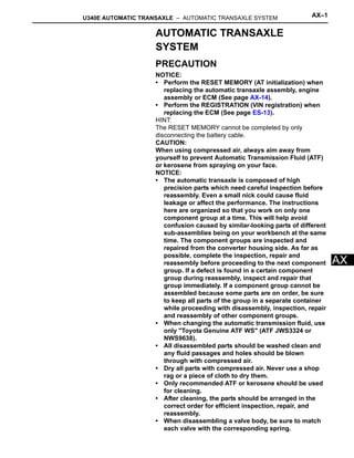
  • 17. U340E AUTOMATIC TRANSAXLE – AUTOMATIC TRANSAXLE SYSTEM AX–17 AX MANUAL SHIFTING TEST 1. PERFORM MANUAL SHIFTING TEST HINT: • This test can be used to determine whether the trouble is occurring in the electrical circuit or is a mechanical problem in the transaxle. • If any abnormalities are found in the following test, the problem is in the transaxle itself. (a) Disconnect the transmission wire connector. HINT: It is possible to deactivate the electrical shift control by disconnecting the transmission wire. In this way, it is possible to change gear positions by mechanical shift change using the shift lever. (b) Drive with the transmission wire disconnected. Shift the shift lever into each position to check whether the gear position changes as shown in the table below. (c) Connect the transmission wire connector. (d) Clear the DTC (See page AX-25). C117640E01 Shift Position Shifting Condition D 3rd 3 3rd 2 3rd L 3rd R Reverse P Pawl Lock
  • 18. AX–18 U340E AUTOMATIC TRANSAXLE – AUTOMATIC TRANSAXLE SYSTEM AX INITIALIZATION 1. RESET MEMORY NOTICE: • Perform the RESET MEMORY (AT initialization) when replacing the automatic transaxle assembly, engine assembly or ECM. • The RESET MEMORY can only be performed using an intelligent tester. HINT: The ECM stores the conditions that the ECT controls the automatic transaxle assembly and engine assembly in accordance with those characteristics. Therefore, when the automatic transaxle assembly, engine assembly, or ECM is replaced, it is necessary to reset the memory so that the ECM can store the new information. The reset procedure is as follows. (a) Turn the ignition switch off. (b) Connect the intelligent tester to the DLC3. (c) Turn the ignition switch to the ON position and push the intelligent tester main switch on. (d) Select the following items: DIAGNOSIS / ENHANCED OBD II. (e) Perform the reset memory procedure from the ENGINE menu. CAUTION: After performing the RESET MEMORY, be sure to perform the ROAD TEST (See page AX-9) as described earlier. HINT: The ECM stores learned values by performing the ROAD TEST. (1) Tester menu flow:
  • 19. U340E AUTOMATIC TRANSAXLE – AUTOMATIC TRANSAXLE SYSTEM AX–19 AX C130151
  • 20. AX–20 U340E AUTOMATIC TRANSAXLE – AUTOMATIC TRANSAXLE SYSTEM AX MONITOR DRIVE PATTERN 1. MONITOR DRIVE PATTERN FOR ECT TEST (a) Perform this drive pattern as one method to simulate the detection conditions of ECT malfunctions. (The DTCs may not be detected due to the actual driving conditions. And some DTCs may not be detected through this drive pattern.) HINT: Preparation for driving • Warm up the engine. (Engine coolant temperature is 60°C (140°F) or higher.) • Drive the vehicle when the atmospheric temperature is -10°C (14°F) or higher. (Malfunction is not detected when the atmospheric temperature is less than -10°C (14°F).) Driving note • Drive the vehicle through all gears. Stop → 1st → 2nd → 3rd → 4th (lock-up ON). • Repeat the above driving pattern three times or more. NOTICE: • The monitor status can be checked using the intelligent tester. When using an intelligent tester, monitor status can be found in the ENHANCED OBD II / DATA LIST or under CARB OBD II. • In the event that the drive pattern must be interrupted (possibly due to traffic conditions or other factors), the drive pattern can be resumed and, in most cases, the monitor can be completed. CAUTION: Perform this drive pattern on as level a road as possible and strictly observe the posted speed limits and traffic laws while driving.
  • 21. U340E AUTOMATIC TRANSAXLE – AUTOMATIC TRANSAXLE SYSTEM AX–21 AX HINT: *1: Drive at such a speed in the uppermost gear, to engage lock-up. The vehicle can be driven at a speed lower than that in the above diagram under the lock-up condition. NOTICE: To detect DTC P0711 (ATF temperature sensor malfunction), drive the vehicle for approximately 30 minutes. Vehicle Speed Maintain constant speed or gradual acceleration (with throttle open) for 3 minutes or more.*1 Lock-up ON Vehicle Speed Stop (Idling) Normal acceleration through all gears from 1st to 4th Warmed up sufficiently 0 Approximately 62 mph (100 km/h) Approximately 50 mph (80 km/h) G031593E14
  • 22. AX–22 U340E AUTOMATIC TRANSAXLE – AUTOMATIC TRANSAXLE SYSTEM AX PROBLEM SYMPTOMS TABLE HINT: • If a normal code is displayed during the DTC check although the trouble still occurs, check the electrical circuits for each symptom in the order given in the following charts and proceed to the page given for troubleshooting. • The Matrix Chart is divided into 2 chapters. • When the circuit on which *1 is attached malfunctions, a DTC could be output. Chapter 1: Electronic Circuit Matrix Chart Refer to the table below when the trouble cause is considered to be electrical. If the trouble still occurs even though there are no abnormalities in any of the other circuits, then check and replace the ECM. Symptom Suspected area See page No up-shift (Particular gear, from 1st to 3rd gear, is not up-shifted) ECM IN-34 No up-shift (From 3rd to 4th) 1. Shift lock control unit circuit AX-47 2. ECM IN-34 No down-shift (From 4th to 3rd) 1. Shift lock control unit circuit AX-47 2. ECM IN-34 No down-shift (Particular gear, from 1st to 3rd gear, is not down-shifted) ECM IN-34 No lock-up or No lock-up off 1. Stop light switch circuit *1 ES-48 2. Engine coolant temperature sensor circuit *1 ES-48 3. Vehicle speed sensor circuit *1 ES-48 4. Speed sensor (NT) circuit *1 AX-50 5. ATF temperature sensor circuit *1 AX-42 6. Shift solenoid valve S1 *1 AX-67 7. Shift solenoid valve S2 *1 AX-71 8. Shift solenoid valve SLU *1 AX-89 9. Throttle position sensor circuit *1 ES-48 10. ECM IN-34 Shift point too high or too low 1. Throttle position sensor circuit *1 ES-48 2. ECM IN-34 Up-shift to 2nd while in L position ECM IN-34 Up-shift to 3nd while in 2 position ECM IN-34 Up-shift from 3rd to 4th in 3 position 1. Shift lock control unit circuit AX-47 2. Park/neutral position switch *1 AX-35 3. ECM IN-34 Up-shift from 3rd to 4th while engine is cold 1. Engine coolant temperature sensor circuit *1 ES-48 2. ECM IN-34 Harsh engagement (From N to D) 1. Park/neutral position switch *1 AX-35 2. ECM IN-34 Harsh engagement (From 3rd to 4th) 1. Shift solenoid valve ST *1 AX-63 2. ECM IN-34 Harsh engagement (Lock-up) 1. Shift solenoid valve SLU *1 AX-89 2. ECM IN-34 Harsh engagement (Any driving position) 1. Throttle position sensor circuit *1 ES-48 2. ECM IN-34 Poor acceleration ECM IN-34 No kick-down ECM IN-34
  • 23. U340E AUTOMATIC TRANSAXLE – AUTOMATIC TRANSAXLE SYSTEM AX–23 AX Chapter 2: On-Vehicle Repair and Off-Vehicle Repair Engine stalls when starting off or stopping ECM IN-34 Malfunction in shifting 1. Park/neutral position switch *1 AX-35 2. Shift lock control unit circuit AX-47 3. ECM IN-34 Symptom Suspected area See page Vehicle does not move in any forward positions or in R position 1. Manual valve AX-253 2. Valve body assembly AX-113 3. Planetary gear unit AX-173 4. Forward clutch (C1) AX-173 5. No. 2 one-way clutch (F2) AX-173 6. Reverse clutch (C3) AX-173 7. 1st and reverse brake (B3) AX-173 Vehicle does not move in R position 1. Manual valve AX-253 2. Valve body assembly AX-113 3. Planetary gear unit AX-173 4. Reverse clutch (C3) AX-173 5. 1st and reverse brake (B3) AX-173 No up-shift (From 1st to 2nd) 1. Valve body assembly AX-113 2. 2nd brake (B2) AX-173 3. No. 1 one-way clutch (F1) AX-173 No up-shift (From 2nd to 3rd) 1. Valve body assembly AX-113 2. Direct clutch (C2) AX-173 No up-shift (From 3rd to 4th) 1. Valve body assembly AX-113 2. O/D and 2nd brake (B1) AX-173 No down-shift (From 4th to 3rd) Valve body assembly AX-113 No down-shift (From 3rd to 2nd) Valve body assembly AX-113 No down-shift (From 2nd to 1st) Valve body assembly AX-113 No lock-up or No lock-up off 1. Valve body assembly AX-113 2. Torque converter clutch AX-171 Harsh engagement (From N to D) 1. Valve body assembly AX-113 2. Forward clutch (C1) AX-173 3. No. 2 one-way clutch (F2) AX-173 Harsh engagement (Lock-up) 1. Valve body assembly AX-113 2. Torque converter clutch AX-171 Harsh engagement (From N to R) 1. Valve body assembly AX-113 2. C3 accumulator AX-173 3. Reverse clutch (C3) AX-173 4. 1st and reverse brake (B3) AX-173 Harsh engagement (From 1st to 2nd) 1. B2 accumulator AX-173 2. Valve body assembly AX-113 3. 2nd brake (B2) AX-173 4. No. 1 one-way clutch (F1) AX-173 Harsh engagement (From 2nd to 3rd) 1. C2 accumulator AX-173 2. Valve body assembly AX-113 3. Direct clutch (C2) AX-173 Harsh engagement (From 3rd to 4th) 1. Shift solenoid valve ST AX-63 2. Valve body assembly AX-113 3. O/D and 2nd brake (B1) AX-173 Symptom Suspected area See page
  • 24. AX–24 U340E AUTOMATIC TRANSAXLE – AUTOMATIC TRANSAXLE SYSTEM AX Harsh engagement (From 4th to 3rd) 1. Shift solenoid valve ST AX-63 2. Valve body assembly AX-113 Harsh engagement (D, 2, L position) Valve body assembly AX-113 Slippage or shuddering (Forward position) 1. Valve body assembly AX-113 2. Oil strainer AX-113 3. Torque converter clutch AX-171 4. Forward clutch (C1) AX-173 5. Direct clutch (C2) AX-173 6. O/D and 2nd brake (B1) AX-173 7. 2nd brake (B2) AX-173 8. No. 1 one-way clutch (F1) AX-173 9. No. 2 one-way clutch (F2) AX-173 Slippage or shuddering (R position) 1. Valve body assembly AX-113 2. Oil strainer AX-113 3. Reverse clutch (C3) AX-173 4. 1st and reverse brake (B3) AX-173 Slippage or shuddering (1st) No. 2 one-way clutch (F2) AX-173 Slippage or shuddering (2nd) 1. 2nd brake (B2) AX-173 2. No.1 one-way clutch (F1) AX-173 Slippage or shuddering (3rd) Direct clutch (C2) AX-173 Slippage or shuddering (4th) O/D and 2nd brake (B1) AX-173 No engine braking (1st: L position) 1. Valve body assembly AX-113 2. 1st and reverse brake (B3) AX-173 No engine braking (2nd: 2 position) 1. Valve body assembly AX-113 2. 2nd and O/D brake (B1) AX-173 No kick-down Valve body assembly AX-113 Poor acceleration 1. Valve body assembly AX-113 2. Torque converter clutch AX-171 Engine stalls when starting off or stopping Torque converter clutch AX-171 Symptom Suspected area See page
  • 25. U340E AUTOMATIC TRANSAXLE – AUTOMATIC TRANSAXLE SYSTEM AX–25 AX TERMINALS OF ECM 1. ECM HINT: Each ECM terminal's standard voltage is shown in the table below. In the table, first follow the information under "Condition". Look under "Symbols (Terminal No.)" for the terminals to be inspected. The standard voltage between the terminals is shown under "Specific Condition". Use the illustration above as a reference for the ECM terminals. 㪈 㪉 㪊 㪋 㪌 㪍 㪎 㪏 㪐 㪈㪇 㪈㪈 㪈㪉 㪈㪊 㪈㪋 㪈㪌 㪈㪍 㪈㪎 㪈㪏 㪈㪐 㪉㪇 㪉㪈 㪉㪉 㪉㪊 㪋㪈 㪋㪉 㪋㪊 㪋㪋 㪋㪌 㪋㪍 㪏㪈 㪏㪉 㪏㪊 㪏㪋 㪏㪌 㪏㪍 㪈㪇㪋 㪈㪇㪌 㪈㪇㪍 㪈㪇㪎 㪈㪇㪏 㪈㪇㪐 㪉㪋 㪉㪌 㪉㪍 㪉㪎 㪉㪏 㪉㪐 㪊㪇 㪊㪈 㪊㪉 㪊㪊 㪊㪋 㪊㪌 㪊㪍 㪊㪎 㪊㪏 㪊㪐 㪋㪇 㪋㪎 㪋㪏 㪋㪐 㪌㪇 㪌㪈 㪌㪉 㪌㪊 㪌㪋 㪌㪌 㪌㪍 㪌㪎 㪌㪏 㪌㪐 㪍㪇 㪍㪈 㪍㪉 㪍㪊 㪍㪋 㪍㪌 㪍㪍 㪍㪎 㪍㪏 㪍㪐 㪎㪇 㪎㪈 㪎㪉 㪎㪊 㪎㪋 㪎㪌 㪎㪍 㪎㪎 㪎㪏 㪎㪐 㪏㪇 㪏㪎 㪏㪏 㪏㪐 㪐㪇 㪐㪈 㪐㪉 㪐㪊 㪐㪋 㪐㪌 㪐㪍 㪐㪎 㪐㪏 㪐㪐 㪈㪇㪇 㪈㪇㪈 㪈㪇㪉 㪈㪇㪊 㪈㪈㪇 㪈㪈㪈 㪈㪈㪉 㪈㪈㪊 㪈㪈㪋 㪈㪈㪌 㪈㪈㪍 㪈㪈㪎 㪈㪈㪏 㪈㪈㪐 㪈㪉㪇 㪈㪉㪈 㪈㪉㪉 㪈㪉㪊 㪈㪉㪋 㪈㪉㪌 㪈㪉㪍 㪈 㪋 㪌 㪍 㪎 㪏 㪐 㪈㪇 㪈㪈 㪈㪉 㪈㪊 㪈㪋 㪈㪌 㪈㪍 㪈㪎 㪈㪏 㪈㪐 㪉㪊 㪉㪋 㪉㪌 㪉㪍 㪉㪎 㪉㪏 㪉㪐 㪊㪇 㪊㪋 㪊㪌 㪊㪍 㪊㪎 㪊㪏 㪊㪐 㪋㪇 㪋㪈 㪋㪉 㪋㪊 㪋㪋 㪋㪌 㪋㪍 㪋㪎 㪋㪏 㪋㪐 㪌㪊 㪌㪋 㪌㪌 㪌㪍 㪌㪎 㪌㪏 㪌㪐 㪍㪇 㪉 㪊 㪉㪇 㪉㪈 㪉㪉 㪊㪈 㪊㪉 㪊㪊 㪌㪇 㪌㪈 㪌㪉 C20 A21 C105085E01 Symbols (Terminals No.) Wiring Color Terminal Description Condition Specified Condition L (C20-74) - E1 (C20-104) V - W L shift position switch signal Ignition switch ON and shift lever L position 11 to 14 V Ignition switch ON and shift lever other than L position Below 1 V 2 (C20-55) - E1 (C20-104) G - W 2 shift position switch signal Ignition switch ON and shift lever 2 position 11 to 14 V Ignition switch ON and shift lever other than 2 position Below 1 V ODMS (A21-26) - E1 (C20-104) O - W 3 shift position switch signal Ignition switch ON and shift lever 3 position 11 to 14 V Ignition switch ON and shift lever other than 3 position Below 1 V D (C20-56) - E1 (C20-104) L - W D shift position switch signal Ignition switch ON and shift lever D or 3 position 11 to 14 V Ignition switch ON and shift lever other than D and 3 positions Below 1 V R (C20-53) - E1 (C20-104) R - W R shift position switch signal Ignition switch ON and shift lever R position 11 to 14 V Ignition switch ON and shift lever other than R position Below 1 V
  • 26. AX–26 U340E AUTOMATIC TRANSAXLE – AUTOMATIC TRANSAXLE SYSTEM AX (a) Waveform 1 (b) Waveform 2 N (C20-54) - E1 (C20-104) SB - W N shift position switch signal Ignition switch ON and shift lever N position 11 to 14 V Ignition switch ON and shift lever other than N position Below 1 V P (C20-73) - E1 (C20-104) R - W P shift position switch signal Ignition switch ON and shift lever P position 11 to 14 V Ignition switch ON and shift lever other than P position Below 1 V NT+ (C20-125) - NT- (C20-124) B - G Speed sensor (NT) signal Engine running Pulse generation (See waveform 1) STP (A21-36) - E1 (C20- 104) G - W Stop light switch signal Brake pedal depressed 7.5 to 14 V Brake pedal released Below 1.5 V SPD (A21-8) - E1 (C20- 104) V - W Speed signal Ignition switch ON and driving wheel rotating slowly Pulse generation (See waveform 2) S1 (C20-79) - E1 (C20- 104) SB - W S1 solenoid signal Ignition switch ON 11 to 14 V 1st or 2nd gear 11 to 14 V 3rd or 4th gear Below 1 V S2 (C20-78) - E1 (C20- 104) L - W S2 solenoid signal Ignition switch ON Below 1 V 1st or 4th gear 11 to 14 V 2nd or 3rd gear Below 1 V ST (C20-80) - E1 (C20- 104) GR - W ST solenoid signal D position (3rd gear ←→ 4th gear) Below 1 V ←→ 11 to 14 V SLT+ (C20-76) - SLT- (C20-75) G - W SLT solenoid signal Engine idling speed Pulse generation (See waveform 3) SLU+ (C20-57) - SLU- (C20-77) P - O SLU solenoid signal Engine idling speed Pulse generation (See waveform 4) THO1 (C20-72) - ETHO (C20-95) Y - B ATF (Automatic Transmission Fluid) temperature sensor signal ATF temperature: 10°C (50°F) to 145°C (293°F) 4 to 0 V Symbols (Terminals No.) Wiring Color Terminal Description Condition Specified Condition 2 V/DIV 1 ms/DIV C053419E04 Terminal NT+ - NT- Tool setting 2 V/DIV, 1ms/DIV Vehicle conditions Driving at approximately 12 mph (20 km/h) 2 V/DIV 20 ms/DIV C053421E04 Terminal SPD - E1 Tool setting 2 V/DIV, 20 ms/DIV Vehicle conditions Driving at approximately 12 mph (20 km/h)
  • 27. U340E AUTOMATIC TRANSAXLE – AUTOMATIC TRANSAXLE SYSTEM AX–27 AX (c) Waveform 3 (d) Waveform 4 5 V/DIV 1 ms/DIV C055887E01 Terminal SLT+ - SLT- Tool setting 5 V/DIV, 1 ms/DIV Vehicle conditions Engine idling speed 5 V/DIV 1 ms/DIV C058033E01 Terminal SLU+ - SLU- Tool setting 5 V/DIV, 1 ms/DIV Vehicle conditions Engine idling speed
  • 28. AX–28 U340E AUTOMATIC TRANSAXLE – AUTOMATIC TRANSAXLE SYSTEM AX DIAGNOSIS SYSTEM 1. DESCRIPTION (a) When troubleshooting OBD II vehicles, the only difference from the usual troubleshooting procedure is to connect an intelligent tester (complying with SAE J1987) to the vehicle, and read off various data output by the vehicle's ECM. (b) OBD II regulations require that the vehicle's on- board computer illuminate the Malfunction Indicator Lamp (MIL) on the instrument panel when the computer detects a malfunction in the computer itself or in the drive system components which affect the vehicle emissions. In addition to illuminating the MIL when a malfunction is detected, the applicable DTCs prescribed by SAE J2012 are recorded in the ECM memory (See page AX-32). If the malfunction does not occur in 3 consecutive trips, the MIL goes off but the DTCs remain in the ECM memory. (c) To check the DTCs, connect the intelligent tester to the DLC3 of the vehicle. The intelligent tester also enables you to erase the DTCs and check freeze frame data and various forms of engine data (For operating instructions, see the instruction book). (d) The DTCs include SAE controlled codes and manufacturer controlled codes. SAE controlled codes must be set as prescribed by the SAE, while manufacturer controlled codes can be set freely by the manufacturer within the prescribed limits (See page AX-32). (e) The diagnosis system operates in normal mode during normal vehicle use. In normal mode, 2-trip detection logic is used to ensure accurate detection of malfunctions. Check mode is also available to technicians as an option. In check mode, 1-trip detection logic is used for simulating malfunction symptoms and increasing the system's ability to detect malfunctions, including intermittent malfunctions. (f) 2-trip detection logic: When a malfunction is first detected, the malfunction is temporarily stored in the ECM memory (1st trip). If the ignition switch is turned off and then turned to the ON position again, and same malfunction is detected again, the MIL illuminates. FI00534 Intelligent Tester CAN VIM DLC3 C115104E01
  • 29. U340E AUTOMATIC TRANSAXLE – AUTOMATIC TRANSAXLE SYSTEM AX–29 AX (g) Freeze frame data records the engine conditions, such as fuel system, calculated load, engine coolant temperature, fuel trim, engine speed and vehicle speed when a malfunction is detected. When troubleshooting, freeze frame data can help determine if the vehicle was running or stopped, if the engine was warmed up or not, if the air/fuel ratio was lean or rich, and other data from the time the malfunction occurred. (h) The intelligent tester records freeze frame data in five different instances: 1) 3 times before the DTC is set, 2) once when the DTC is set, and 3) once after the DTC is set. These data can be used to simulate the vehicle's conditions around the time when the malfunction occurred. The data may help find the cause of the malfunction, or judge if the DTC is being caused by a temporary malfunction or not. 2. INSPECT DLC3 (a) The ECM uses ISO 15765-4 for communication. The terminal arrangement of the DLC3 complies with SAE J1962 and matches the ISO 15765-4 format. NOTICE: * : Before measuring the resistance, leave the vehicle as is for at least 1 minute and do not operate the ignition switch, any other switches or the doors. 0.5 0.5 0.5 (Seconds) A092901E12 1 2 3 4 5 6 7 8 9 10 111213141516 CG DLC3 SG SIL BAT CANH CANL A082779E81 Symbols (Terminal No.) Terminal Description Condition Specified Condition SIL (7) - SG (5) Bus "+" line During transmission Pulse generation CG (4) - Body ground Chassis ground Always Below 1 Ω SG (5) - Body ground Signal ground Always Below 1 Ω BAT (16) - Body ground Battery positive Always 11 to 14 V CANH (6) - CANL (14) CAN bus line Ignition switch OFF* 54 to 69 Ω CANH (6) - CG (4) HIGH-level CAN bus line Ignition switch OFF* 200 Ω or higher CANL (14) - CG (4) LOW-level CAN bus line Ignition switch OFF* 200 Ω or higher CANH (6) - BAT (16) HIGH-level CAN bus line Ignition switch OFF* 6 kΩ or higher CANL (14) - BAT (16) LOW-level CAN bus line Ignition switch OFF* 6 kΩ or higher
  • 30. AX–30 U340E AUTOMATIC TRANSAXLE – AUTOMATIC TRANSAXLE SYSTEM AX If the result is not as specified, the DLC3 may have a malfunction. Repair or replace the harness and connector. HINT: If your display shows UNABLE TO CONNECT TO VEHICLE when you have connected the cable of the intelligent tester to the DLC3, turned the ignition switch to the ON position and operated the tester, there is a problem with the vehicle or the tester. • If the communication is normal when the tester is connected to another vehicle, inspect the DLC3 on the original vehicle. • If the communication is still impossible when the tester is connected to another vehicle, the problem is probably in the tester itself. Consult the Service Department listed in the tester's instruction manual. 3. CHECK BATTERY VOLTAGE (a) Measure the battery voltage. Standard voltage: 11 to 14 V If the voltage is below 11 V, replace the battery before proceeding. 4. CHECK MIL (a) The MIL comes on when the ignition switch is turned to the ON position and the engine is not running. HINT: If the MIL does not light up, troubleshoot the combination meter. (b) When the engine is started, the MIL should go off. If the lamp remains on, it means that the diagnosis system has detected a malfunction or abnormality in the system.
  • 31. U340E AUTOMATIC TRANSAXLE – AUTOMATIC TRANSAXLE SYSTEM AX–31 AX DTC CHECK / CLEAR 1. DTC CHECK (NORMAL MODE) NOTICE: When the diagnostic system is switched from normal mode to check mode, all the DTCs and freeze frame data recorded in normal mode are erased. So before switching modes, always check the DTCs and freeze frame data, and note them down. (a) Check DTCs using an intelligent tester. (1) Turn the ignition switch off. (2) Connect the intelligent tester to the DLC3. (3) Turn the ignition switch to the ON position and turn the intelligent tester main switch on. (4) Select the following items: DIAGNOSIS / ENHANCED OBD II / DTC INFO / CURRENT CODES. (5) Read the DTCs and freeze frame data displayed on the tester and note them down. NOTICE: When simulating symptoms with an intelligent tester to check the DTCs, use normal mode. For DTCs in the DTC chart, which are subject to 2-trip detection logic, perform the following. Turn the ignition switch off after the symptom is simulated once. Then repeat the simulation process again. When the problem has been simulated twice, the MIL illuminates and the DTCs are recorded in the ECM. 2. DTC CLEAR (a) Clear the DTCs: When using an intelligent tester. (1) Connect the intelligent tester to the DLC3. (2) Turn the ignition switch to the ON position and turn the intelligent tester main switch on. (3) Select the following items: DIAGNOSIS / ENHANCED OBD II / DTC INFO / CLEAR CODES [YES] button. HINT: When operating the intelligent tester to erase the DTCs, the freeze frame data are also erased. (b) Clear the DTCs: When not using an intelligent tester. (1) Disconnect the battery terminal or remove the EFI and ETCS fuses from the engine room J/B for 60 seconds or more. Intelligent Tester CAN VIM DLC3 C115104E07
  • 32. AX–32 U340E AUTOMATIC TRANSAXLE – AUTOMATIC TRANSAXLE SYSTEM AX CHECK MODE PROCEDURE 1. DESCRIPTION (a) Check mode has a higher sensitivity to malfunctions and can detect malfunctions that normal mode cannot detect. Check mode can also detect all the malfunctions that normal mode can detect. In check mode, DTCs are detected with 1-trip detection logic. 2. DTC CHECK (CHECK MODE) HINT: Intelligent tester only: Compared to normal mode, check mode is more sensitive for detecting malfunctions. Furthermore, the same diagnostic items which are detected in normal mode can also be detected in check mode. (a) Procedure for check mode using the intelligent tester. (1) Check the initial conditions. • Battery positive voltage 11 V or more • Throttle valve fully closed • Transaxle in the P or N position • A/C switched OFF (2) Turn the ignition switch off. (3) Connect the intelligent tester to the DLC3. (4) Turn the ignition switch to the ON position and turn the intelligent tester main switch on. (5) Select the following items: DIAGNOSIS / ENHANCED OBD II / CHECK MODE (Check that the MIL flashes as shown in the illustration). NOTICE: All DTCs and freeze frame data recorded are erased if: 1) the intelligent tester is used to change the ECM from normal mode to check mode or vice-versa; or 2) during check mode, the ignition switch is turned from the ON position to the ACC or LOCK position. (6) Start the engine (the MIL goes off after the engine starts). (7) Perform MONITOR DRIVE PATTERN for the ECT test (See page AX-16), or simulate the conditions of the malfunction described by the customer. NOTICE: Leave the ignition switch in the ON position until you have checked the DTCs. (8) After simulating malfunction conditions, use the intelligent tester to check the DTCs and freeze frame data. Intelligent Tester CAN VIM DLC3 C115104E07 ON OFF 0.13 seconds 0.13 seconds A076900E17
  • 33. U340E AUTOMATIC TRANSAXLE – AUTOMATIC TRANSAXLE SYSTEM AX–33 AX FAIL-SAFE CHART 1. FAIL-SAFE (a) This function minimizes the loss of ECT functions when any malfunction occurs in the sensors or solenoids. (b) Fail-safe chart for shift solenoid valve S1 and/or S2: Fail safe function: If either of the shift solenoid valve circuits develops an open or short, the ECM turns the other shift solenoid ON or OFF in order to shift into the gear positions shown in the table below. Manual shifting as shown in the following table must be done (In case of a short circuit, the ECM stops sending the current to the short circuit solenoid). Even if starting the engine in fail-safe mode, the gear position remains in the same position. Normal: Shift Solenoid Valve S1 malfunction: Malfunction Part Function Vehicle Speed Sensor During vehicle speed sensor signal malfunction, 4th up-shift is prohibited. Transmission Revolution Sensor (Speed Sensor (NT)) During transmission revolution sensor (NT) signal malfunction, 4th up- shift is prohibited. ATF (Automatic Transmission Fluid) Temperature Sensor During ATF temperature sensor malfunction, 4th up-shift is prohibited. Shift Solenoid Valve S1 or S2 During shift solenoid valve S1 or S2 malfunction, current to faulty shift solenoid valve is cut off and control is effected by operating normal solenoid valve. Shift control effect depends on failed solenoid as described in table below. Shift Solenoid Valve ST During shift solenoid valve ST malfunction, 4th up-shift is prohibited. Shift Solenoid Valve SLT During shift solenoid valve SLT malfunction, 4th up-shift is prohibited. Engine Coolant Temperature Sensor, Knock Sensor or Throttle Position Sensor During engine coolant temperature sensor, knock sensor or throttle position sensor malfunction, 4th up-shift is prohibited. Shift Lever Position Shift Solenoid Valve S1 Shift Solenoid Valve S2 Gear D 1st ON ON 1st 2nd ON OFF 2nd 3rd OFF OFF 3rd 4th OFF ON 4th 3 1st ON ON 1st 2nd ON OFF 2nd 3rd OFF OFF 3rd 2 1st ON ON 1st 2nd ON OFF 2nd L 1st ON ON 1st Shift Lever Position Shift Solenoid Valve S1 Shift Solenoid Valve S2 Gear D 1st X OFF 3rd 2nd X OFF 3rd 3rd X OFF 3rd 4th X ON 4th 3 1st X OFF 3rd 2nd X OFF 3rd 3rd X OFF 3rd
  • 34. AX–34 U340E AUTOMATIC TRANSAXLE – AUTOMATIC TRANSAXLE SYSTEM AX X: Malfunctions Shift Solenoid Valve S2 malfunction: X: Malfunctions Shift Solenoid Valve S1 and S2 malfunction: X: Malfunctions 2 1st X OFF 3rd 2nd X OFF 3rd L 1st X OFF 3rd Shift Lever Position Shift Solenoid Valve S1 Shift Solenoid Valve S2 Gear Shift Lever Position Shift Solenoid Valve S1 Shift Solenoid Valve S2 Gear D 1st ON X 2nd 2nd ON X 2nd 3rd OFF X 3rd 4th OFF X 3rd 3 1st ON X 2nd 2nd ON X 2nd 3rd OFF X 3rd 2 1st ON X 2nd 2nd ON X 2nd L 1st ON X 2nd Shift Lever Position Shift Solenoid Valve S1 Shift Solenoid Valve S2 Gear D 1st X X 3rd 2nd X X 3rd 3rd X X 3rd 4th X X 3rd 3 1st X X 3rd 2nd X X 3rd 3rd X X 3rd 2 1st X X 3rd 2nd X X 3rd L 1st X X 3rd
  • 35. U340E AUTOMATIC TRANSAXLE – AUTOMATIC TRANSAXLE SYSTEM AX–35 AX DATA LIST / ACTIVE TEST 1. DATA LIST HINT: Using the DATA LIST displayed by the intelligent tester, you can read the values of the switches, sensors, actuators and so on without parts removal. Reading the DATA LIST as the first step of troubleshooting is one method of shortening labor time. NOTICE: In the table below, the values listed under "Normal Condition" are reference values. Do not depend solely on these reference values when deciding whether a part is faulty or not. (a) Warm up the engine. (b) Turn the ignition switch off. (c) Connect the intelligent tester together with the CAN VIM (Controller Area Network Vehicle Interface Module) to the DLC3. (d) Turn the ignition switch to the ON position. (e) Turn on the tester. (f) Select the following items: DIAGNOSIS / ENHANCED OBD II / DATA LIST. (g) In accordance with the display on the tester, read the DATA LIST. Item Measurement Item/ Range (display) Normal Condition Diagnostic Note VEHICLE SPD Vehicle Speed display/ min.: 0 mph (0 km/h) max.: 158 mph (255 km/h) • Vehicle stopped: 0 mph (0 km/h) • Same as speedometer reading - SPD (NT) Input Turbine Speed/ display: 50 rpm min.: 0 rpm max.: 12750 rpm HINT: • Lock-Up ON (After warming up engine): Input turbine speed (NT) equal to engine speed • Lock-Up OFF (Idling at P or N position): Input turbine speed (NT) nearly equal to engine speed • Vehicle stopped in D position: 0 rpm - PNP SW [NSW] PNP SW Status/ ON or OFF Shift lever position; P or N: ON Except P and N: OFF When shift lever position displayed on intelligent tester differs from actual position, adjustment of PNP switch or shift cable may be incorrect. HINT: When failure still occurs even after adjusting these parts, see page AX-35. STOP LIGHT SW Stop Light SW Status/ ON or OFF • Brake pedal is depressed: ON • Brake pedal is released: OFF - SHIFT ECM Gearshift Command/ 1st, 2nd, 3rd or 4th Shift lever position; • L: 1st • 2: 1st or 2nd • 3: 1st, 2nd or 3rd • D: 1st, 2nd, 3rd or 4th -
  • 36. AX–36 U340E AUTOMATIC TRANSAXLE – AUTOMATIC TRANSAXLE SYSTEM AX 2. ACTIVE TEST HINT: Performing the ACTIVE TEST using the intelligent tester allows the relay, VSV, actuator and so on to operate without parts removal. Performing the ACTIVE TEST as the first step of troubleshooting is one method to shorten labor time. It is possible to display the DATA LIST during the ACTIVE TEST. (a) Warm up the engine. (b) Turn the ignition switch off. REVERSE PNP SW Status/ ON or OFF Shift lever position; R: ON Except R: OFF When shift lever position displayed on intelligent tester differs from actual position, adjustment of PNP switch or shift cable may be incorrect. HINT: When failure still occurs even after adjusting these parts, see page AX-35. PARKING PNP SW Status/ ON or OFF Shift lever position; P: ON Except P: OFF NEUTRAL PNP SW Status/ ON or OFF Shift lever position; N: ON Except N: OFF DRIVE PNP SW Status/ ON or OFF Shift lever position; D or 3: ON Except D and 3: OFF 3RD PNP SW Status/ ON or OFF Shift lever position; 3: ON Except 3: OFF - 2ND PNP SW Status/ ON or OFF Shift lever position; 2: ON Except 2: OFF When shift lever position displayed on intelligent tester differs from actual position, adjustment of PNP switch or shift cable may be incorrect. HINT: When failure still occurs even after adjusting these parts, see page AX-35. LOW PNP SW Status/ ON or OFF Shift lever position; L: ON Except L: OFF A/T OIL TEMP1 ATF (Automatic Transmission Fluid) Temperature Sensor Value/ min.: -40°C (-40°F) max.: 215°C (419°F) • After Stall Test; Approximately 80°C (176°F) • Equal to ambient temperature when cold soak If value is "-40°C (-40°F)" or " 150°C (302°F) or more ", ATF temperature sensor circuit is open or short. ATF ATF Condition ATF Condition; NG: ON OK: OFF Replace ATF when ATF condition is ON. LOCK UP Lock Up Status/ ON or OFF • Lock Up: ON • Except Lock Up: OFF - LOCK UP SOL Lock Up Solenoid Status/ ON or OFF • Lock up solenoid ON: ON • Lock up solenoid OFF: OFF - SOLENOID (ST) Shift Solenoid ST Status/ ON or OFF Up-shifting and down-shifting between 3rd and 4th gears while driving: OFF → ON → OFF - SOLENOID (SLU) Shift Solenoid SLU Status/ ON or OFF • Lock Up: ON • Except Lock Up: OFF - SOLENOID (SLT) Shift Solenoid SLT Status/ ON or OFF • Accelerator pedal is depressed: OFF • Accelerator pedal is released: ON - Item Measurement Item/ Range (display) Normal Condition Diagnostic Note
  • 37. U340E AUTOMATIC TRANSAXLE – AUTOMATIC TRANSAXLE SYSTEM AX–37 AX (c) Connect the intelligent tester together with the CAN VIM (Controller Area Network Vehicle Interface Module) to the DLC3. (d) Turn the ignition switch to the ON position. (e) Turn on the tester. (f) Select the following items: DIAGNOSIS / ENHANCED OBD II / ACTIVE TEST. (g) In accordance with the display on the tester, perform the ACTIVE TEST. Item Test Details Diagnostic Note SOLENOID (SLU) [Test Details] Operate shift solenoid SLU [Vehicle Condition] • Vehicle Stopped • Shift lever P or N position - SOLENOID (SLT)* [Test Details] Operate shift solenoid SLT and raise the line pressure. [Vehicle Condition] • Vehicle Stopped • IDL: ON HINT: OFF: Line pressure up (When the active test of "SOLENOID (SLT)" is performed, ECM commands SLT solenoid to turn off.) ON: No action (normal operation) - SOLENOID (S1) [Test Details] Operate shift solenoid S1 [Vehicle Condition] • Vehicle Stopped • Shift lever P or N position - SOLENOID (S2) [Test Details] Operate shift solenoid S2 [Vehicle Condition] • Vehicle Stopped • Shift lever P or N position - LOCK UP [Test Details] Control shift solenoid SLU to set automatic transaxle to lock-up condition. [Vehicle Condition] Vehicle Speed: 36 mph (60 km/h) or more, and 4th gear Possible to check SLU operation. SHIFT [Test Details] Operate shift solenoid valve and set each shift position manually. [Vehicle Condition] Vehicle Speed: Less than 30 mph (50 km/h) [Others] • Press →button: Shift up • Press ←button: Shift down Possible to check operation of shift solenoid valves. SOLENOID (ST) [Test Details] Operate shift solenoid ST [Vehicle Condition] • Vehicle Stopped • IDL: ON -
  • 38. AX–38 U340E AUTOMATIC TRANSAXLE – AUTOMATIC TRANSAXLE SYSTEM AX *: SOLENOID (SLT) in the ACTIVE TEST is performed to check the line pressure changes by connecting SST to the automatic transaxle, which is used in the HYDRAULIC TEST (See page AX-13) as well. HINT: The pressure values in ACTIVE TEST and HYDRAULIC TEST are different from each other.
  • 39. U340E AUTOMATIC TRANSAXLE – AUTOMATIC TRANSAXLE SYSTEM AX–39 AX DIAGNOSTIC TROUBLE CODE CHART If a DTC is displayed during the DTC check, check the parts listed in the table below and proceed to the page given. HINT: • *1: "Comes on" means the MIL (Malfunction Indicator Lamp) illuminates. • * 2: "DTC stored" means the ECM stores the malfunction code if the ECM detects the DTC detection condition. • These DTCs may be output when the clutch, brake and gear components inside the automatic transaxle are damaged. AUTOMATIC TRANSMISSION SYSTEM DTC No. Detection Item Trouble Area MIL *1 Memory *2 See page P0705 Transmission Range Sensor Circuit Malfunction (PRNDL Input) 1. Open or short in park/neutral position switch circuit 2. Park/neutral position switch 3. Shift lock control ECU 4. ECM Comes on DTC stored AX-35 P0710 Transmission Fluid Temperature Sensor "A" Circuit 1. Open or short in ATF temperature sensor circuit 2. Transmission wire (ATF temperature sensor) 3. ECM Comes on DTC stored AX-42 P0711 Transmission Fluid Temperature Sensor "A" Performance 1. ATF level 2. Transmission wire (ATF temperature sensor) 3. ECM Comes on DTC stored AX-47 P0712 Transmission Fluid Temperature Sensor "A" Circuit Low Input 1. Short in ATF temperature sensor circuit 2. Transmission wire (ATF temperature sensor) 3. ECM Comes on DTC stored AX-42 P0713 Transmission Fluid Temperature Sensor "A" Circuit High Input 1. Open in ATF temperature sensor circuit 2. Transmission wire (ATF temperature sensor) 3. ECM Comes on DTC stored AX-42 P0717 Turbine Speed Sensor Circuit No Signal 1. Open or short in transmission revolution sensor (Speed sensor (NT)) circuit 2. Transmission revolution sensor 3. Automatic transaxle (clutch, brake or gear etc.) 4. ECM Comes on DTC stored AX-50
  • 40. AX–40 U340E AUTOMATIC TRANSAXLE – AUTOMATIC TRANSAXLE SYSTEM AX P0751 Shift Solenoid "A" Performance (Shift Solenoid Valve S1) 1. Shift solenoid valve S1 remains open or closed 2. Valve body is blocked 3. Shift solenoid valve S1 4. Automatic transaxle (clutch, brake or gear etc.) 5. ECM Comes on DTC stored AX-53 P0756 Shift Solenoid "B" Performance (Shift Solenoid Valve S2) 1. Shift solenoid valve S2 remains open or closed 2. Valve body is blocked 3. Shift solenoid valve S2 4. Automatic transaxle (clutch, brake or gear etc.) 5. ECM Comes on DTC stored AX-58 P0787 Shift / Timing Solenoid Low (Shift Solenoid Valve ST) 1. Short in shift solenoid valve ST circuit 2. Shift solenoid valve ST 3. ECM Comes on DTC stored AX-63 P0788 Shift / Timing Solenoid High (Shift Solenoid Valve ST) 1. Open in shift solenoid valve ST circuit 2. Shift solenoid valve ST 3. ECM Comes on DTC stored AX-63 P0973 Shift Solenoid "A" Control Circuit Low (Shift Solenoid Valve S1) 1. Short in shift solenoid valve S1 circuit 2. Shift solenoid valve S1 3. ECM Comes on DTC stored AX-67 P0974 Shift Solenoid "A" Control Circuit High (Shift Solenoid Valve S1) 1. Open in shift solenoid valve S1 circuit 2. Shift solenoid valve S1 3. ECM Comes on DTC stored AX-67 P0976 Shift Solenoid "B" Control Circuit Low (Shift Solenoid Valve S2) 1. Short in shift solenoid valve S2 circuit 2. Shift solenoid valve S2 3. ECM Comes on DTC stored AX-71 P0977 Shift Solenoid "B" Control Circuit High (Shift Solenoid Valve S2) 1. Open in shift solenoid valve S2 circuit 2. Shift solenoid valve S2 3. ECM Comes on DTC stored AX-71 DTC No. Detection Item Trouble Area MIL *1 Memory *2 See page
  • 41. U340E AUTOMATIC TRANSAXLE – AUTOMATIC TRANSAXLE SYSTEM AX–41 AX P2714 Pressure Control Solenoid "D" Performance (Shift Solenoid Valve SLT) 1. Shift solenoid valve SLT remains open or closed 2. Valve body is blocked 3. Torque converter clutch 4. Automatic transaxle (clutch, brake or gear etc.) 5. ECM Comes on DTC stored AX-75 P2716 Pressure Control Solenoid "D" Electrical (Shift Solenoid Valve SLT) 1. Open or short in shift solenoid valve SLT circuit 2. Shift solenoid valve SLT 3. ECM Comes on DTC stored AX-80 P2757 Torque Converter Clutch Pressure Control Solenoid Performance (Shift Solenoid Valve SLU) 1. Shift solenoid valve SLU remains open or closed 2. Valve body is blocked 3. Shift solenoid valve SLU 4. Torque converter clutch 5. Automatic transaxle (clutch, brake or gear etc.) 6. Line pressure is too low 7. ECM Comes on DTC stored AX-84 P2759 Torque Converter Clutch Pressure Control Solenoid Control Circuit Electrical (Shift Solenoid Valve SLU) 1. Open or short in shift solenoid valve SLU circuit 2. Shift solenoid valve SLU 3. ECM Comes on DTC stored AX-89 DTC No. Detection Item Trouble Area MIL *1 Memory *2 See page
  • 42. AX–42 U340E AUTOMATIC TRANSAXLE – AUTOMATIC TRANSAXLE SYSTEM AX DESCRIPTION The park/neutral position switch detects the shift lever position and sends signals to the ECM. MONITOR DESCRIPTION This DTC indicates a problem with the park/neutral position switch and the wire harness in the park/ neutral position switch circuit. The park/neutral position switch detects the shift lever position and sends a signal to the ECM. For safety, the park/neutral position switch detects the shift lever position so that the engine can be started only when the shift lever is in the P or N position. The park/neutral position switch sends a signal to the ECM according to the shift position (P, R, N, D, 2 or L). The ECM determines that there is a problem with the switch or related parts if it receives 2 or more position signals simultaneously. The ECM turns on the MIL and stores the DTC. MONITOR STRATEGY TYPICAL ENABLING CONDITIONS TYPICAL MALFUNCTION THRESHOLDS One of the following conditions is met: Condition (a), (b) or (c) Condition (a): DTC P0705 Transmission Range Sensor Circuit Malfunc- tion (PRNDL Input) DTC No. DTC Detection Condition Trouble Area P0705 (a) Any 2 or more of following signals are ON simultaneously. (2-trip detection logic) • P input signal • R input signal • N input signal • D input signal • 2 input signal • L input signal (b) All switches are OFF simultaneously for P, R, N, D, 2 and L positions. (2-trip detection logic) (c) L or 3 input signal is ON for P, R or N position. (2-trip detection logic) • Open or short in park/neutral position switch circuit • Park/neutral position switch • Shift lock control ECU • ECM Related DTCs P0705: Park/neutral position switch/Verify switch input Required sensors/Components Park/neutral position switch Frequency of operation Continuous Duration Condition (a) and (c): 2 seconds Condition (b): 60 seconds MIL operation 2 driving cycles Sequence of operation None The monitor runs whenever the following DTCs are not present. None Ignition switch ON Battery voltage 10.5 V or more Number of following signals input simultaneously 2 or more P switch ON R switch ON N switch ON D switch ON
  • 43. U340E AUTOMATIC TRANSAXLE – AUTOMATIC TRANSAXLE SYSTEM AX–43 AX Condition (b): All of the following conditions are met. Condition (c): When shift lever is in P, R or N position, either of following conditions is met. COMPONENT OPERATING RANGE WIRING DIAGRAM 2 switch ON L switch ON P switch OFF R switch OFF N switch OFF D switch OFF 2 switch OFF L switch OFF 3 switch ON L switch ON Park/neutral position switch The park/neutral position switch sends only one signal to the ECM. Park/Neutral Position Switch ECM PL RL NL DL 2L LL P R N D 2 L NSSD AT3 D22 Shift Lock Control ECU ODMS RB To Gauge Fuse C27 C20 A21 C117646E02
  • 44. AX–44 U340E AUTOMATIC TRANSAXLE – AUTOMATIC TRANSAXLE SYSTEM AX INSPECTION PROCEDURE 1. DATA LIST HINT: Using the DATA LIST displayed by the intelligent tester, you can read the values of the switches, sensors, actuators and so on without parts removal. Reading the DATA LIST as the first step of troubleshooting is one method of shortening labor time. (a) Turn the ignition switch off. (b) Connect the intelligent tester together with the CAN VIM (Controller Area Network Vehicle Interface Module) to the DLC3. (c) Turn the ignition switch to the ON position. (d) Turn on the tester. (e) Select the following items: DIAGNOSIS / ENHANCED OBD II / DATA LIST. (f) In accordance with the display on the tester, read the DATA LIST. (a) Connect the intelligent tester to the DLC3. (b) Turn the ignition switch to the ON position. (c) Turn on the intelligent tester. (d) Select the following items: DIAGNOSIS / ENHANCED OBD II / DATA LIST. Item Measurement Item/ Range (display) Normal Condition Diagnostic Note REVERSE PNP (Park/Neutral Position) SW Status/ ON or OFF Shift lever position; R: ON Except R: OFF When shift lever position displayed on intelligent tester differs from actual position, adjustment of PNP switch or shift cable may be incorrect. PARKING PNP SW Status/ ON or OFF Shift lever position; P: ON Except P: OFF NEUTRAL PNP SW Status/ ON or OFF Shift lever position; N: ON Except N: OFF DRIVE PNP SW Status/ ON or OFF Shift lever position; D or 3: ON Except D and 3: OFF 3RD PNP SW Status/ ON or OFF Shift lever position; 3: ON Except 3: OFF - 2ND PNP SW Status/ ON or OFF Shift lever position; 2: ON Except 2: OFF When shift lever position displayed on intelligent tester differs from actual position, adjustment of PNP switch or shift cable may be incorrect. LOW PNP SW Status/ ON or OFF Shift lever position; L: ON Except L: OFF 1 READ VALUE OF DATA LIST (PARK/NEUTRAL POSITION SWITCH)
  • 45. U340E AUTOMATIC TRANSAXLE – AUTOMATIC TRANSAXLE SYSTEM AX–45 AX (e) In accordance with the display on the tester, read the DATA LIST. OK NG (a) Disconnect the park/neutral position switch connector. (b) Turn the ignition switch to the ON position, and measure the voltage. Standard voltage NG OK Item Measurement Item/ Range (display) Normal Condition Diagnostic Note REVERSE PNP (Park/Neutral Position) SW Status/ ON or OFF Shift lever position; R: ON Except R: OFF When shift lever position displayed on intelligent tester differs from actual position, adjustment of PNP switch or shift cable may be incorrect. PARKING PNP SW Status/ ON or OFF Shift lever position; P: ON Except P: OFF NEUTRAL PNP SW Status/ ON or OFF Shift lever position; N: ON Except N: OFF DRIVE PNP SW Status/ ON or OFF Shift lever position; D or 3: ON Except D and 3: OFF 2ND PNP SW Status/ ON or OFF Shift lever position; 2: ON Except 2: OFF LOW PNP SW Status/ ON or OFF Shift lever position; L: ON Except L: OFF Go to step 5 2 CHECK HARNESS AND CONNECTOR (POWER SOURCE OF PARK/NEUTRAL POSITION SWITCH) 1 2 3 4 9 8 7 6 5 C27 (Connector Front View) Wire Harness Side: RB C117645E01 Tester Connection Specified Condition 2 (RB) - Body ground 11 to 14 V CHECK POWER SOURCE OF ECM
  • 46. AX–46 U340E AUTOMATIC TRANSAXLE – AUTOMATIC TRANSAXLE SYSTEM AX (a) Disconnect the park/neutral position switch connector. (b) Measure the resistance when the shift lever is moved to each position. Standard resistance NG OK (a) Connect the park/neutral position switch connector. (b) Disconnect the ECM connector. (c) Turn the ignition switch to the ON position, and measure the voltage when the shift lever is moved to each position. Standard voltage 3 INSPECT PARK/NEUTRAL POSITION SWITCH ASSEMBLY 1 2 3 4 9 8 7 6 5 Component Side: (Connector Front View) C27 RL RB 2L NL LL DL PL B L C130119E04 Shift Position Tester Connection Specified Condition P or N 4 (B) - 5 (L) Below 1 Ω Except P and N 4 (B) - 5 (L) 10 kΩ or higher P 2 (RB) - 6 (PL) Below 1 Ω Except P 2 (RB) - 6 (PL) 10 kΩ or higher R 1 (RL) - 2 (RB) Below 1 Ω Except R 1 (RL) - 2 (RB) 10 kΩ or higher N 2 (RB) - 9 (NL) Below 1 Ω Except N 2 (RB) - 9 (NL) 10 kΩ or higher D or 3 2 (RB) - 7 (DL) Below 1 Ω Except D and 3 2 (RB) - 7 (DL) 10 kΩ or higher 2 2 (RB) - 3 (2L) Below 1 Ω Except 2 2 (RB) - 3 (2L) 10 kΩ or higher L 2 (RB) - 8 (LL) Below 1 Ω Except L 2 (RB) - 8 (LL) 10 kΩ or higher REPLACE PARK/NEUTRAL POSITION SWITCH ASSEMBLY 4 CHECK HARNESS AND CONNECTOR (PARK/NEUTRAL POSITION SWITCH - ECM) C20 Wire Harness Side: (Connector Front View) L P R 2 D N C130155E01 Shift Position Tester Connection Specified Condition P 73 (P) - Body ground 11 to 14 V Except P 73 (P) - Body ground Below 1 V R 53 (R) - Body ground 11 to 14 V* Except R 53 (R) - Body ground Below 1 V N 54 (N) - Body ground 11 to 14 V Except N 54 (N) - Body ground Below 1 V D or 3 56 (D) - Body ground 11 to 14 V Except D and 3 56 (D) - Body ground Below 1 V 2 55 (2) - Body ground 11 to 14 V Except 2 55 (2) - Body ground Below 1 V L 74 (L) - Body ground 11 to 14 V Except L 74 (L) - Body ground Below 1 V
  • 47. U340E AUTOMATIC TRANSAXLE – AUTOMATIC TRANSAXLE SYSTEM AX–47 AX HINT: *: The voltage will drop slightly due to the back up light being turned on. NG OK (a) Connect the ECM connector. (b) Turn the ignition switch to the ON position. (c) Turn on the intelligent tester. (d) Select the following items: DIAGNOSIS / ENHANCED OBD II / DATA LIST. (e) In accordance with the display on the tester, read the DATA LIST. OK NG (a) Disconnect the shift lock control ECU connector. (b) Turn the ignition switch to the ON position, and measure the voltage when the shift lever is moved to each position. Standard voltage NG OK REPAIR OR REPLACE HARNESS OR CONNECTOR 5 READ VALUE OF DATA LIST (PARK/NEUTRAL POSITION SWITCH) Item Measurement Item/ Range (display) Normal Condition 3RD PNP SW Status/ ON or OFF Shift lever position; 3: ON Except 3: OFF CHECK FOR INTERMITTENT PROBLEMS 6 CHECK HARNESS AND CONNECTOR (PARK/NEUTRAL POSITION SWITCH - SHIFT LOCK CONTROL ECU) D22 (Connector Front View) Wire Harness Side: E NSSD C117647E01 Shift Position Tester Connection Specified Condition D or 3 9 (NSSD) - 8 (E) 11 to 14 V Except D and 3 9 (NSSD) - 8 (E) Below 1 V REPAIR OR REPLACE HARNESS OR CONNECTOR
  • 48. AX–48 U340E AUTOMATIC TRANSAXLE – AUTOMATIC TRANSAXLE SYSTEM AX (a) Disconnect the shift lock control ECU connector. (b) Measure the resistance when the shift lever is moved to each position. Standard resistance NG OK (a) Connect the shift lock control ECU connector. (b) Disconnect the ECM connectors. (c) Turn the ignition switch to the ON position, and measure the voltage. Standard voltage NG OK 7 INSPECT SHIFT LOCK CONTROL ECU SUB-ASSEMBLY D22 (Connector Front View) Component Side: NSSD AT3 C117648E02 Shift Position Tester Connection Specified Condition 3 3 (AT3) - 9 (NSSD) Below 1 Ω D 3 (AT3) - 9 (NSSD) 10 kΩ or higher REPLACE SHIFT LOCK CONTROL ECU SUB-ASSEMBLY 8 CHECK HARNESS AND CONNECTOR (SHIFT LOCK CONTROL ECU - ECM) A21 ODMS Wire Harness Side: (Connector Front View) A115671E41 Shift Position Tester Connection Specified Condition 3 26 (ODMS) - Body ground 11 to 14 V Except 3 26 (ODMS) - Body ground Below 1 V REPAIR OR REPLACE HARNESS OR CONNECTOR REPLACE ECM
  • 49. U340E AUTOMATIC TRANSAXLE – AUTOMATIC TRANSAXLE SYSTEM AX–49 AX DESCRIPTION The ATF (Automatic Transmission Fluid) temperature sensor converts the fluid temperature into a resistance value which is input to the ECM. The sensor resistance changes with the transmission fluid temperature. As the temperature rises, the sensor resistance decreases. The ECM applies a voltage to the temperature sensor through ECM terminal THO1, and the ECM calculates the fluid temperature based on the voltage signal. HINT: • The ATF temperature is likely to increase under conditions such as towing, climbing hills and in heavy traffic. • When the ATF temperature sensor is normal, the transmission locks up in 4th gear with the shift lever in the D position and in 3rd gear with the shift lever in the 3rd position. DTC P0710 Transmission Fluid Temperature Sensor "A" Circuit DTC P0712 Transmission Fluid Temperature Sensor "A" Circuit Low Input DTC P0713 Transmission Fluid Temperature Sensor "A" Circuit High Input DTC No. DTC Detection Condition Trouble Area P0710 Both (a) and (b) are detected momentarily within 0.5 seconds when neither P0712 nor P0713 is detected. (1- trip detection logic) (a) ATF temperature sensor resistance is less than 79 Ω. (b) ATF temperature sensor resistance is more than 156 kΩ. HINT: Within 0.5 seconds, malfunction switches from (a) to (b) or from (b) to (a). • Open or short in ATF temperature sensor circuit • Transmission wire (ATF temperature sensor) • ECM Acceptable Temperature Resistance G031389E08
  • 50. AX–50 U340E AUTOMATIC TRANSAXLE – AUTOMATIC TRANSAXLE SYSTEM AX MONITOR DESCRIPTION The ATF temperature sensor converts the ATF temperature to an electrical resistance value. Based on the resistance, the ECM determines the ATF temperature and detects opens or shorts in the ATF temperature circuit. If the resistance value of the ATF temperature is less than 79 Ω* 1 or more than 156 kΩ* 2, the ECM interprets this as a fault in the ATF sensor or wiring. The ECM turns on the MIL and stores the DTC. * 1: 150°C (302°F) or more is indicated regardless of the actual ATF temperature. *2: -40°C (-40°F) is indicated regardless of the actual ATF temperature. HINT: The ATF temperature can be checked on the intelligent tester display. MONITOR STRATEGY *1: Transmission Fluid Temperature TYPICAL ENABLING CONDITIONS P0710: Range check (Fluttering) P0712: Range check (Low resistance) P0713: Range check (High resistance) TYPICAL MALFUNCTION THRESHOLDS P0710: Range check (Fluttering) P0712: Range check (Low resistance) P0712 ATF temperature sensor resistance is less than 79 Ω for 0.5 seconds or more. (1-trip detection logic) • Short in ATF temperature sensor circuit • Transmission wire (ATF temperature sensor) • ECM P0713 Following condition continues for 0.5 seconds or more. (1-trip detection logic) ATF temperature sensor resistance is more than 156 kΩ after 15 minutes or more after starting engine. • Open in ATF temperature sensor circuit • Transmission wire (ATF temperature sensor) • ECM Related DTCs P0710: ATF temperature sensor/Range check (Fluttering) P0712: ATF temperature sensor/Range check (Low resistance) P0713: ATF temperature sensor/Range check (High resistance) Required sensors/Components ATF temperature sensor (TFT*1 sensor) Frequency of operation Continuous Duration 0.5 seconds MIL operation Immediate Sequence of operation None The monitor runs whenever the following DTCs are not present. None The typical enabling conditions are not available. - The monitor runs whenever the following DTCs are not present. None The typical enabling conditions are not available. - The monitor runs whenever the following DTCs are not present. None Time after engine start 15 minutes or more ATF temperature sensor (TFT sensor) resistance Less than 79 Ω or More than 156 kΩ ATF temperature sensor (TFT sensor) resistance Less than 79 Ω DTC No. DTC Detection Condition Trouble Area
  • 51. U340E AUTOMATIC TRANSAXLE – AUTOMATIC TRANSAXLE SYSTEM AX–51 AX P0713: Range check (High resistance) COMPONENT OPERATING RANGE WIRING DIAGRAM INSPECTION PROCEDURE 1. DATA LIST HINT: Using the DATA LIST displayed by the intelligent tester, you can read the values of the switches, sensors, actuators and so on without parts removal. Reading the DATA LIST as the first step of troubleshooting is one method of shortening labor time. NOTICE: In the table below, the values listed under "Normal Condition" are reference values. Do not depend solely on these reference values when deciding whether a part is faulty or not. (a) Warm up the engine. (b) Turn the ignition switch off. (c) Connect the intelligent tester together with the CAN VIM (Controller Area Network Vehicle Interface Module) to the DLC3. (d) Turn the ignition switch to the ON position. (e) Turn on the tester. (f) Select the following items: DIAGNOSIS / ENHANCED OBD II / DATA LIST. (g) In accordance with the display on the tester, read the DATA LIST. HINT: When DTC P0712 is output and the intelligent tester reading is 150°C (302°F) or more, there is a short circuit. When DTC P0713 is output and the intelligent tester reading is -40°C (-40°F), there is an open circuit. ATF temperature sensor (TFT sensor) resistance More than 156 kΩ ATF temperature sensor (TFT sensor) resistance Resistance: 79 Ω to 156 kΩ Item Measurement Item/ Range (display) Normal Condition Diagnostic Note A/T OIL TEMP1 ATF Temperature Sensor Value/ min.: -40°C (-40°F) max.: 215°C (419°F) • After Stall Test; Approximately 80°C (176°F) • Equal to ambient temperature when cold soak If value is -40°C (-40°F) or 150°C (302°F) or more, ATF temperature sensor circuit is open or short. C28 Electronically Controlled Transmission Solenoid THO E2 THO1 ETHO ECM 5 V (ATF Temperature Sensor) C117649E02
  • 52. AX–52 U340E AUTOMATIC TRANSAXLE – AUTOMATIC TRANSAXLE SYSTEM AX Measure the resistance between terminal THO1 and the body ground. HINT: If a circuit related to the ATF (Automatic Transmission Fluid) temperature sensor becomes open, P0713 is immediately set (within 0.5 seconds). (a) Disconnect the transmission wire connector from the transaxle. (b) Measure the resistance. Standard resistance HINT: If the resistance is outside the specified range at either of the ATF temperatures shown in the table below, the driveability of the vehicle may be affected. Standard resistance NG OK (a) Connect the transmission wire connector to the transaxle. (b) Disconnect the ECM connector. (c) Measure the resistance. Standard resistance NG Temperature Displayed Malfunction -40°C (-40°F) Open circuit 150°C (302°F) or more Short circuit 1 INSPECT TRANSMISSION WIRE (ATF TEMPERATURE SENSOR) C28 (Connector Front View) Component Side: THO E2 C117650E01 Tester Connection Specified Condition 1 (THO) - 6 (E2) 79 Ω to 156 kΩ 1 (THO) - Body ground 10 kΩ or higher 6 (E2) - Body ground 10 kΩ or higher ATF Temperature Specified Condition 20°C (68°F) 3 to 4 kΩ 110°C (230°F) 0.22 to 0.28 kΩ REPAIR OR REPLACE TRANSMISSION WIRE 2 CHECK HARNESS AND CONNECTOR (TRANSMISSION WIRE - ECM) C20 Wire Harness Side: (Connector Front View) THO1 ETHO A107892E03 Tester Connection Specified Condition 72 (THO1) - 95 (ETHO) 79 Ω to 156 kΩ 72 (THO1) - Body ground 10 kΩ or higher 95 (ETHO) - Body ground 10 kΩ or higher REPAIR OR REPLACE HARNESS OR CONNECTOR
  • 53. U340E AUTOMATIC TRANSAXLE – AUTOMATIC TRANSAXLE SYSTEM AX–53 AX OK REPLACE ECM
  • 54. AX–54 U340E AUTOMATIC TRANSAXLE – AUTOMATIC TRANSAXLE SYSTEM AX DESCRIPTION The ATF (Automatic Transmission Fluid) temperature sensor converts the fluid temperature into a resistance value which is input to the ECM. The sensor resistance changes with the transmission fluid temperature. As the temperature rises, the sensor resistance decreases. The ECM applies a voltage to the temperature sensor through ECM terminal THO1, and the ECM calculates the fluid temperature based on the voltage signal. HINT: • The ATF temperature is likely to increase under conditions such as towing, climbing hills and in traffic. • When the ATF temperature sensor is normal, the transmission locks up in 4th gear with the shift lever in the D position and in 3rd gear with the shift lever in the 3rd position. MONITOR DESCRIPTION The ATF temperature sensor converts the ATF temperature to an electrical resistance value. Based on the resistance, the ECM determines the ATF temperature and detects opens or shorts in the ATF temperature circuit or a fault of the ATF temperature sensor. After running the vehicle for a certain period, the ATF temperature should increase. If the ATF temperature is below 20°C (68°F) after running the vehicle for a certain period, the ECM interprets this as a fault, and turns on the MIL. When the ATF temperature is 100°C (212°F) or more and engine coolant temperature reaches 60°C (140°F) after cold start, the ECM also determines this as a fault, turns on the MIL, and stores the DTC. MONITOR STRATEGY *: Transmission Fluid Temperature DTC P0711 Transmission Fluid Temperature Sensor "A" Performance DTC No. DTC Detection Condition Trouble Area P0711 Either of the following Condition (A) or (B) is met: Condition (A): All of (a), (b) and (c) are detected (2-trip detection logic): (a) Intake air and engine coolant temperatures are more than -10°C (14°F) at engine start. (b) After normal driving for over 9 minutes and 5.6 miles (9 km) or more, ATF temperature is less than 20°C (68°F). (c) 19 minutes or more have elapsed after engine start. Condition (B): Both (a) and (b) are detected (2-trip detection logic) (a) Engine coolant temperature is less than 35°C (95°F) at engine start. (b) ATF temperature is 100°C (212°F) or more when engine coolant temperature reaches 60°C (140°F). • ATF level • Transmission wire (ATF temperature sensor) • ECM Related DTCs P0711: ATF temperature sensor/Rationality check Required sensors/Components ATF temperature sensor (TFT* sensor) Frequency of operation Continuous Duration Condition (A): 3 seconds Condition (B): 10 seconds MIL operation 2 driving cycles Sequence of operation None
  • 55. U340E AUTOMATIC TRANSAXLE – AUTOMATIC TRANSAXLE SYSTEM AX–55 AX TYPICAL ENABLING CONDITIONS The following conditions are common to Condition (A) and (B). Condition (A): Condition (B): TYPICAL MALFUNCTION THRESHOLDS Either of the following conditions is met: Condition (A) or (B) Condition (A): Condition (B): COMPONENT OPERATING RANGE INSPECTION PROCEDURE 1. DATA LIST HINT: Using the DATA LIST displayed by the intelligent tester, you can read the values of the switches, sensors, actuators and so on without parts removal. Reading the DATA LIST as the first step of troubleshooting is one method of shortening labor time. NOTICE: In the table below, the values listed under "Normal Condition" are reference values. Do not depend solely on these reference values when deciding whether a part is faulty or not. (a) Warm up the engine. (b) Turn the ignition switch off. (c) Connect the intelligent tester together with the CAN VIM (Controller Area Network Vehicle Interface Module) to the DLC3. (d) Turn the ignition switch to the ON position. (e) Turn on the tester. (f) Select the following items: DIAGNOSIS / ENHANCED OBD II / DATA LIST. The monitor runs whenever the following DTCs are not present. None ATF temperature sensor (TFT sensor) circuit No circuit malfunction ECT (Engine Coolant Temperature) sensor circuit No circuit malfunction IAT (Intake Air Temperature) sensor circuit No circuit malfunction Electronic Throttle Control System (if applicable) No circuit malfunction Time after engine start 18 minutes and 20 seconds or more Driving distance after engine start 5.6 mile (9 km) or more Accumulated driving time 9 minutes and 10 seconds or more ECT -15°C (5°F) or more IAT (12 seconds after engine start) -10°C (14°F) or more ECT (12 seconds after engine start) -10°C (14°F) or more ECT (Current temperature) 60°C (140°F) or more ECT (12 seconds after engine start) Less than 35°C (95°F) ATF temperature (12 seconds after engine start) 100°C (212°F) or more ATF temperature Less than 20°C (68°F) ATF temperature 100°C (212°F) or more ATF temperature 20°C (68°F) or more and less than 100°C (212°F) under specific condition
  • 56. AX–56 U340E AUTOMATIC TRANSAXLE – AUTOMATIC TRANSAXLE SYSTEM AX (g) In accordance with the display on the tester, read the DATA LIST. HINT: When DTC P0712 is output and intelligent tester reading is 150°C (302°F) or more, there is a short circuit. When DTC P0713 is output and intelligent tester reading is -40°C (-40°F), there is an open circuit. Measure the resistance between terminal THO1 and the body ground. HINT: If a circuit related to the ATF (Automatic Transmission Fluid) temperature sensor becomes open, P0713 is immediately set (within 0.5 seconds). It is not necessary to inspect the circuit when P0711 is set. (a) Connect the intelligent tester to the DLC3. (b) Turn the ignition switch to the ON position. (c) Turn on the tester. (d) Select the following items: DIAGNOSIS / ENHANCED OBD II / DTC INFO / CURRENT CODES. (e) Read the DTCs using the tester. Result HINT: If any DTCs codes besides P0711 are output, perform troubleshooting for those DTCs first. B A OK: Automatic transmission fluid level is correct. NG OK Item Measurement Item/ Range (display) Normal Condition A/T OIL TEMP1 ATF Temperature Sensor Value/ min.: -40°C (-40°F) max.: 215°C (419°F) • After Stall Test; Approximately 80°C (176°F) • Equal to ambient temperature when cold soak Temperature Displayed Malfunction -40°C (-40°F) Open circuit 150°C (302°F) or more Short circuit 1 CHECK OTHER DTCS OUTPUT (IN ADDITION TO DTC P0711) Display (DTC output) Proceed to P0711 A P0711 and other DTCs B GO TO DTC CHART 2 CHECK TRANSMISSION FLUID LEVEL ADD FLUID REPLACE TRANSMISSION WIRE (ATF TEMPERATURE SENSOR)
  • 57. U340E AUTOMATIC TRANSAXLE – AUTOMATIC TRANSAXLE SYSTEM AX–57 AX DESCRIPTION This sensor detects the rotation speed of the input turbine. By comparing the input turbine speed signal (NT) with the speed sensor signal (SPD), the ECM detects the shift timing of the gears and appropriately controls the engine torque and hydraulic pressure in response to various conditions, thus performing smooth gear shifting. MONITOR DESCRIPTION The ECM detects the revolving signal from the transmission revolution sensor (input RPM). The ECM outputs a gearshift signal by comparing the transmission revolution sensor signal with the speed sensor signal (SPD). While the vehicle is operating in the 3rd or 4th gear position in the shift position of D, if the input shaft revolution is less than 300 rpm*1 although the output shaft revolution is more than 1,000 rpm*2, the ECM detects the malfunction, illuminates the MIL and stores the DTC. * 1: Pulse is not output or is irregularly output. *2: The vehicle speed is 31 mph (50 km/h) or more. MONITOR STRATEGY TYPICAL ENABLING CONDITIONS DTC P0717 Turbine Speed Sensor Circuit No Signal DTC No. DTC Detection Condition Trouble Area P0717 All conditions below are detected for 5 seconds or more. (1-trip detection logic) (a) Gear change is not being performed. (b) Gear position: 3rd or 4th (c) T/M input shaft rpm: 300 rpm or less (d) T/M output shaft rpm: 1,000 rpm or more (e) Park/neutral position switch (NSW, R and L) is OFF. (f) Shift solenoid valves, park/neutral position switch and vehicle speed sensor are in normal operation. • Open or short in transmission revolution sensor (Speed sensor (NT)) circuit • Transmission revolution sensor • Automatic transaxle (clutch, brake or gear etc.) • ECM Related DTCs P0717: Turbine speed sensor/Verify pulse input Required sensors/Components Transmission revolution sensor (Speed sensor (NT)) Frequency of operation Continuous Duration 5 seconds MIL operation Immediate Sequence of operation None The monitor runs whenever the following DTCs are not present. P0500 (VSS) P0748 - P0798 (Trans solenoid (range)) Shift change After shift change is completed and before starting next shift change operation ECM selected gear 3rd or 4th Output shaft rpm 1,000 rpm or more Park/neutral position switch OFF R switch OFF L switch OFF Transmission range switch fail Not detected Battery voltage 8 V or more Ignition switch ON Starter OFF Engine Running
  • 58. AX–58 U340E AUTOMATIC TRANSAXLE – AUTOMATIC TRANSAXLE SYSTEM AX TYPICAL MALFUNCTION THRESHOLDS COMPONENT OPERATING RANGE WIRING DIAGRAM INSPECTION PROCEDURE (a) Check the transmission revolution sensor installation. OK: The installation bolt is tightened properly and there is no clearance between the sensor and transmission case. NG OK Sensor signal rpm Less than 300 rpm Transmission revolution sensor (speed sensor (NT)) Input turbine speed is equal to engine speed when lock-up ON 1 INSPECT TRANSMISSION REVOLUTION SENSOR (NT) INSTALLATION 2 1 ECM NT+ NT- E1 Transmission Revolution Sensor (Speed Sensor (NT)) C29 C130125E03 OK NG BR03795E36 SECURELY INSTALL OR REPLACE TRANSMISSION REVOLUTION SENSOR
  • 59. U340E AUTOMATIC TRANSAXLE – AUTOMATIC TRANSAXLE SYSTEM AX–59 AX (a) Disconnect the transmission revolution sensor connector from the transaxle. (b) Measure the resistance. Standard resistance NG OK (a) Connect the transmission revolution sensor connector. (b) Disconnect the ECM connector. (c) Measure the resistance. Standard resistance NG OK 2 INSPECT TRANSMISSION REVOLUTION SENSOR 1 2 Sensor Side: (Connector Front View): C29 C110343E29 Tester Connection Specified Condition 1 - 2 560 Ω to 680 kΩ at 20°C (68°F) SECURELY INSTALL OR REPLACE TRANSMISSION REVOLUTION SENSOR 3 CHECK HARNESS AND CONNECTOR (TRANSMISSION REVOLUTION SENSOR - ECM) C20 Wire Harness Side: (Connector Front View) NT- NT+ A107892E04 Tester Connection Specified Condition 125 (NT+) - 124 (NT-) 560 to 680 kΩ at 20°C (68°F) 125 (NT+) - Body ground 10 kΩ or higher 124 (NT-) - Body ground 10 kΩ or higher REPAIR OR REPLACE HARNESS OR CONNECTOR REPLACE ECM
  • 60. AX–60 U340E AUTOMATIC TRANSAXLE – AUTOMATIC TRANSAXLE SYSTEM AX DESCRIPTION The ECM uses signals from the vehicle speed sensor and speed sensor NT to detect the actual gear position (1st, 2nd, 3rd or 4th). Then the ECM compares the actual gear with the shift schedule in the ECM memory to detect the mechanical problems of the shift solenoid valves, the valve body or automatic transaxle (clutch, brake or gear etc.). HINT: Gear positions in the event of a solenoid valve mechanical problem: MONITOR DESCRIPTION This DTC indicates "stuck ON malfunction" or "stuck OFF malfunction" of shift solenoid valve S1. The ECM controls the gearshifts by turning the shift solenoid valves ON/OFF. When the gear position directed by the ECM and the actual gear position do not match, the ECM illuminates the MIL and stores the DTC. MONITOR STRATEGY DTC P0751 Shift Solenoid "A" Performance (Shift Solenoid Valve S1) DTC No. DTC Detection Condition Trouble Area P0751 S1 stuck OFF malfunction* 1: ECM determines there is malfunction when both of following conditions are met: (2-trip detection logic) (a) When ECM directs gearshift to switch to 1st gear, actual gear is shifted to 4th. (b) When ECM directs gearshift to switch to 4th gear, actual gear is shifted to 4th. • Shift solenoid valve S1 remains closed • Valve body is blocked • Shift solenoid valve S1 • Automatic transaxle (clutch, brake or gear etc.) • ECM P0751 S1 stuck ON malfunction* 2: ECM determines that there is malfunction when both of following conditions are met: (2-trip detection logic) (a) When ECM directs gearshift to switch from 3rd to 4th gear, actual gear is not shifted as above. (b) When ECM directs gearshift to switch to 4th gear, engine speed surges 1,100 rpm or more. • Shift solenoid valve S1 remains open • Valve body is blocked • Shift solenoid valve S1 • Automatic transaxle (clutch, brake or gear etc.) • ECM Gearshift controlled by ECM 1st 2nd 3rd 4th *1: Actual gear position under S1 stuck OFF malfunction 4th 3rd 3rd 4th *2: Actual gear position under S1 stuck ON malfunction 1st 2nd 2nd 1st Related DTCs P0751: Shift solenoid valve S1/OFF malfunction Shift solenoid valve S1/ON malfunction Required sensors/Components Shift solenoid valve S1, Speed sensor (NT), Speed sensor (SPD) Frequency of operation Continuous Duration OFF malfunction (a): 0.85 seconds OFF malfunction (b): 0.8 seconds ON malfunction (a): 0.8 seconds ON malfunction (b): 0.8 seconds MIL operation 2 driving cycle Sequence of operation None
  • 61. U340E AUTOMATIC TRANSAXLE – AUTOMATIC TRANSAXLE SYSTEM AX–61 AX TYPICAL ENABLING CONDITIONS The following conditions are common to all OFF malfunctions and ON malfunctions. OFF malfunction (a): OFF malfunction (b): ON malfunction (a): ON malfunction (b): TYPICAL MALFUNCTION THRESHOLDS [OFF malfunction] Both of the following conditions met: OFF malfunctions (a) and (b) 2 detections are necessary per driving cycle. 1st detection: Temporary flag ON 2nd detection: Pending fault code ON The monitor runs whenever the following DTCs are not present. P0115 - P0118 (ECT sensor) P0125 (Insufficient ECT for closed loop) P0500 (VSS) P0748 - P0798 (Trans solenoid (range)) ECT (Engine Coolant Temperature) 60°C (140°F) or more Time after shifting N to D 4.5 seconds or more Transmission shift position D Shift solenoid valve S1 circuit No circuit malfunction Shift solenoid valve S2 circuit No circuit malfunction ECT sensor circuit No circuit malfunction Electronic Throttle Control System (if applicable) No circuit malfunction Speed sensor (NT) circuit No circuit malfunction Speed sensor (SPD) circuit No circuit malfunction ECM gearshift command 1st Vehicle speed 5.6 mph (9 km/h) or more and Less than 24.9 mph (40 km/h) Throttle valve opening angle 25 % or more and 7.0 % or more at engine speed of 1,900 rpm (Conditions vary with engine speed) ECM gearshift command 4th Last ECM selected gear 3rd ECM gearshift command 4th Last ECM selected gear 3rd ECM gearshift command 4th V current - V last V current: Vehicle speed at current ECM selected gear V last: Vehicle speed at last ECM selected gear Less than 9.3 mph (15 km/h) TH current - TH last TH current: Throttle valve opening angle at current ECM selected gear TH last: Throttle valve opening angle at last ECM selected gear Less than 30 % Vehicle speed (current) Less than 52.8 mph (85 km/h) Throttle valve opening angle (current) Less than 45 % Engine speed (current) 3,200 rpm or more
  • 62. AX–62 U340E AUTOMATIC TRANSAXLE – AUTOMATIC TRANSAXLE SYSTEM AX OFF malfunction (a): OFF malfunction (b): [ON malfunction] Both of the following conditions met: ON malfunctions (a) and (b) ON malfunction (a): ON malfunction (b): INSPECTION PROCEDURE 1. ACTIVE TEST HINT: Performing the ACTIVE TEST using the intelligent tester allows components, such as the relay, VSV, and actuator, to be operated without removing any parts. Performing the ACTIVE TEST as the first step of troubleshooting is one method of shortening labor time. It is possible to display the DATA LIST during the ACTIVE TEST. (a) Warm up the engine. (b) Turn the ignition switch off. (c) Connect the intelligent tester together with the CAN VIM (Controller Area Network Vehicle Interface Module) to the DLC3. (d) Turn the ignition switch to the ON position. (e) Turn on the tester. (f) Select the following items: DIAGNOSIS / ENHANCED OBD II / ACTIVE TEST / SHIFT. (g) In accordance with the display on the tester, perform the ACTIVE TEST. HINT: While driving, the shift position can be forcibly changed using the intelligent tester. Comparing the shift position commanded by the ACTIVE TEST with the actual shift position enables you to confirm the problem (See page AX-27). Input speed/Output speed (NT/NO) NT: Input (turbine) speed NO: Internal counter shaft speed 0.64 or more and less than 0.78 (Current) (This means actual gear is 4th) Input speed/Output speed (NT/NO) Changes as follows 0.95 or more and less than 1.09 (Last) (This means actual gear is 3rd) to 0.64 or more and less than 0.78 (Current) (This means actual gear is 4th) Input speed/Output speed (NT/NO) No change as follows 0.95 or more and less than 1.09 (Last) (This means actual gear is 3rd) to 0.64 or more and less than 0.78 (Current) (This means actual gear is 4th) NE change HINT: NE current - NE last NE current: Engine speed at current ECM selected gear NE last: Engine speed at last ECM selected gear 1,100 rpm or more Item Test Details Diagnostic Note SHIFT [Test Details] Operate shift solenoid valve and set each shift position. [Vehicle Condition] • IDL: ON • 30 mph (50 km/h) or less [Others] • Press "→" button: Shift up • Press "←" button: Shift down Possible to check operation of shift solenoid valves.
  • 63. U340E AUTOMATIC TRANSAXLE – AUTOMATIC TRANSAXLE SYSTEM AX–63 AX HINT: • This test can be conducted when the vehicle speed is 30 mph (50 km/h) or less. • The 3rd to 4th up-shifting must be performed with the accelerator pedal released. • The 4th to 3rd down-shifting must be performed with the accelerator pedal released. • Do not operate the accelerator pedal for at least 2 seconds after shifting and do not shift more than once in succession. • The shift position directed by the ECM is shown in the DATA LIST / SHIFT display on the intelligent tester. • Shift solenoid valve S1 is turned on/off normally when the shift lever is in the D position: (a) Connect the intelligent tester to the DLC3. (b) Turn the ignition switch to the ON position. (c) Turn on the tester. (d) Select the following items: DIAGNOSIS / ENHANCED OBD II / DTC INFO / CURRENT CODES. (e) Read the DTCs using the tester. Result HINT: If any DTCs besides P0751 are output, perform troubleshooting for those DTCs first. B A Gearshift controlled by ECM 1st 2nd 3rd 4th Shift solenoid valve S1 ON ON OFF OFF 1 CHECK OTHER DTCS OUTPUT (IN ADDITION TO DTC P0751) Display (DTC output) Proceed to P0751 A P0751 and other DTCs B GO TO DTC CHART
  • 64. AX–64 U340E AUTOMATIC TRANSAXLE – AUTOMATIC TRANSAXLE SYSTEM AX (a) Remove shift solenoid valve S1. (b) Measure the resistance. Standard resistance (c) Connect the positive (+) lead to the terminal of the solenoid connector and the negative (-) lead to the solenoid body to check the solenoid valve operation. OK: The solenoid makes operating sounds. NG OK OK: There are no foreign objects on any valves and they operate smoothly. NG OK 2 INSPECT SHIFT SOLENOID VALVE S1 B Ω Shift Solenoid Valve S1: (-) (+) C130146E01 Tester Connection Specified Condition Solenoid Connector (S1) - Solenoid Body (S1) 11 to 15 Ω at 20°C (68°F) REPLACE SHIFT SOLENOID VALVE S1 3 INSPECT TRANSMISSION VALVE BODY ASSEMBLY REPAIR OR REPLACE TRANSMISSION VALVE BODY ASSEMBLY REPAIR OR REPLACE AUTOMATIC TRANSAXLE ASSEMBLY
  • 65. U340E AUTOMATIC TRANSAXLE – AUTOMATIC TRANSAXLE SYSTEM AX–65 AX DESCRIPTION The ECM uses signals from the vehicle speed sensor and speed sensor NT to detect the actual gear position (1st, 2nd, 3rd or 4th). Then the ECM compares the actual gear with the shift schedule in the ECM memory to detect the mechanical problems of the shift solenoid valves, the valve body or automatic transaxle (clutch, brake or gear etc.). HINT: Gear positions in the event of a solenoid valve mechanical problem: MONITOR DESCRIPTION This DTC indicates "stuck ON malfunction" or "stuck OFF malfunction" of shift solenoid valve S2. The ECM controls the gearshifts by turning the shift solenoid valves ON/OFF. When the gear position directed by the ECM and the actual gear position do not match, the ECM illuminates the MIL and stores the DTC. MONITOR STRATEGY DTC P0756 Shift Solenoid "B" Performance (Shift Solenoid Valve S2) DTC No. DTC Detection Condition Trouble Area P0756 S2 stuck OFF malfunction* 1: Shifting to 1st and 4th gears is impossible. ECM determines that there is malfunction when all of following conditions are met: (2-trip detection logic) (a) When ECM directs gearshift to switch to 1st gear, actual gear is shifted to 2nd. (b) When ECM directs gearshift to switch to 3rd gear, actual gear is shifted to 3rd. (c) When ECM directs gearshift to switch to 4th gear, actual gear is shifted to 3rd. • Shift solenoid valve S2 remains closed • Valve body is blocked • Shift solenoid valve S2 • Automatic transaxle (clutch, brake or gear etc.) • ECM P0756 S2 stuck ON malfunction* 2: Shifting to 2nd gear and 3rd gear is impossible. ECM determines that there is malfunction when all of following conditions are met: (2-trip detection logic) (a) When ECM directs gearshift to switch to 2nd gear, actual gear is shifted to 1st. (b) When ECM directs gearshift to switch to 3rd gear, actual gear is shifted to 4th. (c) When ECM directs gearshift to switch to 4th gear, actual gear is shifted to 4th. • Shift solenoid valve S2 remains open • Valve body is blocked • Shift solenoid valve S2 • Automatic transaxle (clutch, brake or gear etc.) • ECM Gearshift controlled by ECM 1st 2nd 3rd 4th *1: Actual gear position under S2 stuck OFF malfunction 2nd 2nd 3rd 3rd *2: Actual gear position under S2 stuck ON malfunction 1st 1st 4th 4th Related DTCs P0756: Shift solenoid valve S2/OFF malfunction Shift solenoid valve S2/ON malfunction Required sensors/Components Shift solenoid valve S2, Speed sensor (NT), Speed sensor (SPD) Frequency of operation Continuous Duration 0.85 seconds MIL operation 2 driving cycle Sequence of operation None
  • 66. AX–66 U340E AUTOMATIC TRANSAXLE – AUTOMATIC TRANSAXLE SYSTEM AX TYPICAL ENABLING CONDITIONS The following conditions are common to all OFF malfunctions and ON malfunctions. OFF malfunction (a): OFF malfunction (b): OFF malfunction (c): ON malfunction (a): ON malfunction (b): ON malfunction (c): The monitor runs whenever the following DTCs are not present. P0115 - P0118 (ECT sensor) P0125 (Insufficient ECT for closed loop) P0500 (VSS) P0748 - P0798 (Trans solenoid (range)) ECT (Engine Coolant Temperature) 60°C (140°F) or more Transmission shift position D Time after shifting N to D 4.5 seconds or more Shift solenoid valve S1 circuit No circuit malfunction Shift solenoid valve S2 circuit No circuit malfunction ECT sensor circuit No circuit malfunction Electronic Throttle Control System (if applicable) No circuit malfunction Speed sensor (NT) circuit No circuit malfunction Speed sensor (SPD) circuit No circuit malfunction ECM gearshift command 1st Vehicle speed 5.6 mph (9 km/h) or more and less than 24.9 mph (40 km/h) Throttle valve opening angle 7.0 % or more at engine speed of 1,900 rpm (Conditions vary with engine speed) ECM gearshift command 3rd Vehicle speed 5.6 mph (9 km/h) or more Throttle valve opening angle 7.0 % or more at engine speed of 1,900 rpm (Conditions vary with engine speed) ECM gearshift command 4th Vehicle speed 5.6 mph (9 km/h) or more Throttle valve opening angle 7.0 % or more at engine speed of 1,900 rpm (Conditions vary with engine speed) ECM gearshift command 2nd Vehicle speed 5.6 mph (9 km/h) or more Throttle valve opening angle 7.0 % or more at engine speed of 1,900 rpm (Conditions vary with engine speed) ECM gearshift command 3rd Vehicle speed 5.6 mph (9 km/h) or more Throttle valve opening angle 7.0 % or more at engine speed of 1,900 rpm (Conditions vary with engine speed) ECM gearshift command 4th Vehicle speed 5.6 mph (9 km/h) or more Throttle valve opening angle 7.0 % or more at engine speed of 1,900 rpm (Conditions vary with engine speed)