Application ofasub–0.1-mm3 implantable mote forinvivo real-time wireless temperature sensing
•
0 gostou•48 visualizações

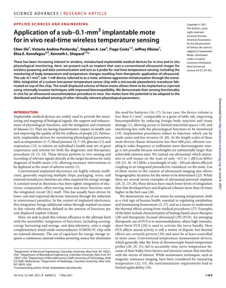
There has been increasing interest in wireless, miniaturized implantable medical devices for invivo and in situphysiological monitoring. Here, we present such an implant that uses a conventional ultrasound imager for wireless powering and data communication and acts as a probe for real-time temperature sensing, including the monitoring of body temperature and temperature changes resulting from therapeutic application of ultrasound.

Recomendados
Recomendados
Mais conteúdo relacionado
Mais procurados
Mais procurados (18)
Semelhante a Application ofasub–0.1-mm3 implantable mote forinvivo real-time wireless temperature sensing
Semelhante a Application ofasub–0.1-mm3 implantable mote forinvivo real-time wireless temperature sensing (20)
Último
Último (20)
Application ofasub–0.1-mm3 implantable mote forinvivo real-time wireless temperature sensing
- 1. Shi et al., Sci. Adv. 2021; 7 : eabf6312 7 May 2021 SCI ENCE ADVANCES | RESEARCH ARTICLE 1 of 9 APPLIED SCIENCES AND ENGINEERING Application of a sub–0.1-mm3 implantable mote for in vivo real-time wireless temperature sensing Chen Shi1 , Victoria Andino-Pavlovsky1 , Stephen A. Lee2 , Tiago Costa1,3 , Jeffrey Elloian1 , Elisa E. Konofagou2,4 , Kenneth L. Shepard1,2 * There has been increasing interest in wireless, miniaturized implantable medical devices for in vivo and in situ physiological monitoring. Here, we present such an implant that uses a conventional ultrasound imager for wireless powering and data communication and acts as a probe for real-time temperature sensing, including the monitoring of body temperature and temperature changes resulting from therapeutic application of ultrasound. The sub–0.1-mm3 , sub–1-nW device, referred to as a mote, achieves aggressive miniaturization through the mono- lithic integration of a custom low-power temperature sensor chip with a microscale piezoelectric transducer fab- ricated on top of the chip. The small displaced volume of these motes allows them to be implanted or injected using minimally invasive techniques with improved biocompatibility. We demonstrate their sensing functionality in vivo for an ultrasound neurostimulation procedure in mice. Our motes have the potential to be adapted to the distributed and localized sensing of other clinically relevant physiological parameters. INTRODUCTION Implantable medical devices are widely used to provide the moni- toring and mapping of biological signals, the support and enhance- ment of physiological functions, and the mitigation and treatment of diseases (1). They are having transformative impact on health care and improving the quality of life for millions of people (2). Particu- larly, implantable devices for monitoring physiological parameters, such as temperature (3–7), blood pressure (4, 7–10), glucose (11), and respiration (12), to inform an individual’s health state are of great importance and interest for both the diagnostic and therapeutic procedures (9, 13, 14). These devices perform in vivo sensing and recording of relevant signals directly at the target locations for early diagnosis of health issues (15), allowing necessary interventions to be deployed at the onset of adverse events (1). Conventional implanted electronics are highly volume ineffi- cient, generally requiring multiple chips, packaging, wires, and external transducers; batteries are often required for energy storage. A constant trend in electronics has been tighter integration of elec- tronic components, often moving more and more functions onto the integrated circuit (IC) itself. This has usually been driven by lower cost and improved electronic functions through the reduction in interconnect parasitics. In the context of implanted electronics, this integration brings additional values through marked increases in this volume efficiency, defined as the amount of functions per unit displaced implant volume. Here, we seek to push this volume efficiency to the ultimate limit with the monolithic integration of functions, including sensing, energy harvesting and storage, and data telemetry, onto a single complementary metal-oxide-semiconductor (CMOS) IC chip with no external elements. The use of capacitors for energy storage re- quires a continuous external wireless powering source but eliminates the need for batteries (16, 17). In our case, the device volume is less than 0.1 mm3 , comparable to a grain of table salt, improving biocompatibility by reducing foreign body rejection and tissue damage (1), allowing access to limited interstitial spaces (18), and interfering less with the physiological functions to be monitored (19). Implantation procedures reduce to injection, which can be made easier and less invasive (9, 20). At the length scales of these mote devices (linear dimensions less than 600 m), efficient cou- pling to radio-frequency or millimeter-wave electromagnetic ener- gy is not possible because wavelengths are substantially larger than achievable antenna sizes. We instead use ultrasound, which attenu- ates in soft tissues on the scale of only ~0.5 to 1 dB/(cm·MHz) (20, 21). At ~8.3 MHz, a wavelength of only ~185 m allows efficient coupling to an integrated piezoelectric transducer on the mote. Use of these motes in the context of ultrasound imaging also allows biogeographic locations for the motes to be determined (22). While there are several recent examples of ultrasound-powered implants (20, 21, 23–26), these devices have much lower levels of integration than that developed here and displaced volumes more than 10 times higher in the best case (26). We demonstrate use of our motes for sensing temperature, both as a vital sign of human health, essential in regulating metabolism and maintaining homeostasis (5, 27), and as a means to understand the thermal effects arising from medical procedures (27). Examples of the latter include characterization of heating-based cancer therapies (28) and therapeutic focused ultrasound (29) (FUS). An emerging therapeutic use of FUS is in neuromodulation, where high-intensity, short-burst FUS (29) is used to activate the nerve bundle. How FUS affects neural activity is still a matter of dispute, but thermal effects are certainly present (30) and must be at least controlled in most cases. Conventional temperature measurement devices, which generally take the form of thermocouple-based temperature probes (28, 29, 31), fail to accurately relay nerve temperature be- cause of their bulky form factors and intrusive nature that interfere with the nerves of interest. While noninvasive techniques, such as magnetic resonance imaging, have been considered for measuring temperature (32, 33), the instrumentation requirements lead to limited applicability (34). 1 Department of Electrical Engineering, Columbia University, New York, NY 10027, USA. 2 Department of Biomedical Engineering, Columbia University, New York, NY 10027, USA. 3 Department of Microelectronics, Delft University of Technology, 2628 CD Delft, Netherlands. 4 Department of Radiology, Columbia University, New York, NY 10032, USA. *Corresponding author. Email: shepard@ee.columbia.edu Copyright © 2021 The Authors, some rights reserved; exclusive licensee American Association for the Advancement of Science. No claim to originalU.S. Government Works. Distributed under a Creative Commons Attribution NonCommercial License 4.0 (CC BY-NC). on June 8, 2021 http://advances.sciencemag.org/ Downloaded from
- 2. Shi et al., Sci. Adv. 2021; 7 : eabf6312 7 May 2021 SCI ENCE ADVANCES | RESEARCH ARTICLE 2 of 9 RESULTS Design of the monolithic, ultrasonic mote The mote consists of a temperature sensor IC manufactured in a 0.18-m bulk CMOS technology monolithically integrated (35) with a microscale piezoelectric transducer made of lead zirconate titanate (PZT) (36). Free from any bonding wires, solder joints, and circuit boards, this 0.3-mg mote measures only 380 m by 300 m by 570 m (0.065 mm3 ) with direct mechanical and electrical con- nections between the transducer (300 m by 300 m by 267 m) and the IC. A deconstructed view of the mote is shown in Fig. 1A. The CMOS IC contains two exposed aluminum (Al) pads connected to the input and ground nodes. The input pad is connected to the top side of the transducer, which is covered in 50 nm of electron beam– deposited gold (Au) and connected to the Al input pad with a 1.2-m-thick conformal layer of sputter-deposited copper (Cu). The Al ground pad (250 m by 250 m, which defines the effective area of the transducer) is connected to the 50-nm-thick Au-covered bottom side of the transducer using an anisotropic conductive film (ACF). A layer of 8-m-thick parylene is uniformly deposited over the mote with complete coverage (not shown) to provide biocompati- ble passivation (2, 37, 38) (see Materials and Methods for a more detailed fabrication protocol and fig. S1 for a detailed fabrication schematic). When ultrasound is applied, an output voltage is gener- ated across the two sides of the transducer to power the IC. Figure 1B is a scanning electron microscope (SEM) image of the mote, also shown in scale in Fig. 1C. Figure 1D shows a mote placed at the tip of an 18–gauge (G) needle (0.84-mm inner diameter), highlighting the highly miniaturized form factor of the device. Figure 1E depicts seven motes loaded into a 1-ml syringe filled with phosphate-buffered saline (PBS) ready for an injection delivery. A B C D F E Fig. 1. Miniaturized, monolithically integrated, fully wireless temperature-sensing motes with ultrasound powering and data communication. (A) A decon- structed schematic illustration of the major components of a mote, including a CMOS temperature sensor chip with two exposed Al pads, a microscale PZT transducer covered in Au on both sides, an anisotropic conductive film (ACF), and a Cu layer. (B) An SEM image of the mote, where the PZT transducer is monolithically integrated on the surface of the sensor chip (photo credit: Jeffrey Elloian, Columbia University). The mote is 300 m wide, 380 m long, and 570 m thick (0.065 mm3 ); it weighs 0.3 mg. (C) A picture of a mote placed on a U.S. dime showing the relative size scale (photo credit: Chen Shi, Columbia University). (D) A mote placed at the tip of an 18-G needle (inner diameter, 0.84 mm, outer diameter, 1.28 mm; photo credit: Victoria Andino-Pavlovsky, Columbia University). (E) Seven motes loaded in a 1-ml syringe filled with PBS solution (photo credit: Victoria Andino-Pavlovsky, Columbia University). (F) The system diagram demonstrating the operating principles of such a mote. A Vantage 256 system (Verasonics Inc.) produces a customized ultrasound signal through an L12-3v probe. Such a signal provides power to and receives data from a mote. The embedded sensor chip contains a front-end block to convert the incoming AC signal from the on-chip transducer into a stable DC supply for the rest of the chip, a temperature-sensing block to perform temperature measurements, and a modulation block to transfer the temperature information back to the ultrasound source by actively modifying the input impedance of the integrated PZT transducer. on June 8, 2021 http://advances.sciencemag.org/ Downloaded from
- 3. Shi et al., Sci. Adv. 2021; 7 : eabf6312 7 May 2021 SCI ENCE ADVANCES | RESEARCH ARTICLE 3 of 9 Figure 1F shows the system architecture and block diagram of the mote. A customized and pulsed ultrasound signal (lower left corner of Fig. 1F) is generated with a commercial ultrasound system (Vantage 256, Verasonics) via an ultrasound imaging probe (L12- 3v, Verasonics). In addition to providing power, the imager com- municates to the mote with acoustic backscattering (21) through modulation of the on-chip PZT transducer electrical load. The IC itself [see note S1 for detailed circuit schematics and elaboration on circuit design can be found elsewhere (36)] leverages low-power de- sign approaches by operating most of its transistors in the sub- threshold regime [with a gate-source voltage of around 0 V (39)], reducing power consumption to only ~0.8 nW at physiological temperature (37°C). To overcome the variations of the incoming ultrasound power, the IC features a power-regulating block at the front end for converting the harvested energy from the PZT trans- ducer to a regulated, constant voltage with a conversion efficiency of better than 71%. This voltage serves as the power supply for a temperature sensor based on a relaxation oscillator. The oscillation frequency of the oscillator is designed to vary with temperature by exploiting the temperature dependence of the leakage current flow- ing through a subthreshold-biased transistor. This temperature- dependent oscillator controls a modulator, which places either a high impedance (open) or a low impedance (short) across the trans- ducer periodically, resulting in the modulation of the power of the backscattered ultrasound. Such modulation causes the amplitude of the reflected ultrasound echo to vary in the same frequency as the oscilla- tor. At the ultrasound imager, temperature measurements are made by measuring this oscillation frequency, which shows an exponen- tial relationship with temperatures in the form of f(T ) = A T −0.5 (e B _ T ), where f is the frequency, T is absolute temperature, and A and B are two process-related, temperature-independent constants (36). A fitting curve can be obtained by calibrating at two different tem- peratures, and any temperature can be calculated using this fitting curve and the detected oscillation frequency. In addition, the front- end power regulation results in a temperature error of only 0.088°C (36) within a wide input power range from 0.07 to 0.25 mW/mm2 , expressed as spatial-peak temporal-average intensity (ISPTA). In vitro characterization of mote functions We first characterized the temperature sensing functionality of the motes with an in vitro tissue model. Motes were loaded on a piece of biocompatible polyimide (PI) substrate (inset in Fig. 2A) for handling and separately embedded in a piece of chicken muscle tissue, which was placed on a hot plate for temperature control. The L12-3v ultrasound probe was placed directly above the mote through de- gassed ultrasound gel. An ultrasound image (Fig. 2A) was formed first to locate the mote, which was ~3.5 mm deep in the tissue. A customized ultrasound signal with a duty cycle of ~0.048% and an ISPTA of ~0.044 mW/mm2 [much lower than 7.2 mW/mm2 , the safe exposure limit (20, 21)] successfully powered up the mote, which translates to a theoretical maximum implantation depth of ~5.7 cm assuming an applied energy of 7.2 mW/mm2 and a tissue attenua- tion of 0.5 dB/(cm·MHz). In practice, we have only been able to demonstrate implantation depths up to 2 cm with a reasonable output power of ~1.85 mW/mm2 from the probe primarily because of practical limitations in focusing the incident ultrasound energy and capturing the backscattered signal with a linear-array imaging transducer (see Discussion). This signal, composed of ultrasound pulses separated by 1 ms (Fig. 2B) and configured with a graphical user interface (see note S2), has a pulse repetition rate of 1 kHz, 25 30 35 40 45 50 Temperature ( C) 2 4 6 8 10 12 14 16 18 Frequency (Hz) Mote 1 Mote 2 0 0.2 0.4 0.6 0.8 1 1.2 Time (s) 12 14 16 18 20 Pressure (kPa) −2 −1 0 1 2 Time (ms) −600 −400 −200 0 200 400 600 Pressure (kPa) A B D C Fig. 2. In vitro characterization with two motes embedded in chicken tissues. (A) An ultrasound image showing the mote embedded in chicken tissue (photo credit: Chen Shi, Columbia University). (B) Waveform of the ultrasound signal used to power up and communicate with the mote. (C) Acoustic backscattering data obtained at 37°C for 1.28 s showing the signal and RMS noise levels. (D) Temperature curves for two motes from 25° to 50°C. on June 8, 2021 http://advances.sciencemag.org/ Downloaded from
- 4. Shi et al., Sci. Adv. 2021; 7 : eabf6312 7 May 2021 SCI ENCE ADVANCES | RESEARCH ARTICLE 4 of 9 leading to a minimum detectable change of 1 ms in the oscillation period at a sampling rate of 1 kHz. Each pulse is four cycles at the 8.3-MHz ultrasound carrier frequency (inset in Fig. 2B) with a focal spot size of ~350 m, large enough to accommodate motion in the probe while delivering a focused ultrasound power of approximate- ly 2.75 W at 3.5-mm depth. The temperature of the mote was varied from 25° to 50°C (measured with a reference thermometer placed near the mote), and the acoustic backscattering data was recorded for each swept temperature. A 1.28-s period of backscattering data (1280 data points) measured at 37°C is shown in Fig. 2C. The signal-to-noise ratio (SNR) is ~56.6, large enough to identify the frequency of this signal. Figure 2D plots the temperature-to-frequency curves for two different motes processed from the same wafer, which show similar temperature dependence with a correlation coefficient of 0.9998. The average frequency at 37°C is ~7.72 Hz, and the average tem- perature sensitivity is ~0.45 Hz/°C (5.83%/°C) at this temperature. The average temperature resolution was measured to be ~0.049°C [root mean square (RMS)] at 37°C (see note S3), and the average temperature error was found to be approximately +0.044/−0.040°C from 31° to 35°C (see note S4), both sufficient for physiological temperature measurements (40–42). If a higher temperature error is tolerable for certain applications, then the mote can operate from 25° to 50°C, which covers all the relevant physiological temperatures (5) with a maximum temperature error of approxi- mately ±0.2°C. With an 8.3-MHz operating frequency, the lateral resolution of the imager is ∼280 m and the focal spot size is ∼350 m, both of which are smaller than the physical device size of the motes. The spatial resolution of the sensor is given by the device’s linear dimension, whichis~380 m.Inin vitroexperiments,wehavebeenabletodemon- strate performance of two motes spaced less than 10 m apart. The maximum temporal resolution to measure changes in tem- perature for these sensors is determined by the oscillation frequency with a minimum of one oscillation cycle required for measurement. Therefore, the temporal resolution is 130 ms at 37°C as determined from an oscillation frequency of ~7.7 Hz. Such resolution, comparable to other biomedical sensors (5, 6), is sufficient for most sensing ap- plication with slowly varying physiological temperature changes. In vivo evaluation in mice Motes were then deployed in laboratory mice to evaluate their tem- perature sensing performance in several anatomical locations and as a tool to measure local heating in the context of FUS neuromod- ulation of the sciatic nerve. In all these experiments, degassed and warmed ultrasound gel (see Materials and Methods) was used as the coupling medium for transmitting ultrasound, and a heating pad was used to maintain the animal’s proper body temperature. One of the concerns with using motes for temperature measure- ment is that the motes themselves will result in local heating at the incident ultrasound pressure required for operation. To confirm that this is not the case, motes were calibrated for temperature mea- surement (see note S4) and implanted in two representative anatomi- cal locations, the brain (see Materials and Methods and fig. S6) and the hindlimb (see Materials and Methods and fig. S7). Figure 3A shows the experimental setup for testing on the brain. The L12-3v 0 2 4 6 8 10 Time (min) 33 33.1 33.2 33.3 33.4 33.5 Temperature ( C) Mote Thermometer 0 2 4 6 Time (min) 32 32.5 33 33.5 34 Temperature ( C) Mote Thermometer A B C D Fig. 3. In vivo characterization with motes implanted on the brain and in the hindlimb for measuring core body temperature. (A) The experimental setup with a mote implanted on the brain of a mouse (photo credit: Chen Shi, Columbia University). (B) A continuous temperature recording with the mote implanted on the brain compared to the reference temperature. (C) The experimental setup with a mote implanted in the hindlimb of a mouse (photo credit: Chen Shi, Columbia University). (D) A continuous temperature recording with the mote implanted in the hindlimb compared with the reference temperature. on June 8, 2021 http://advances.sciencemag.org/ Downloaded from
- 5. Shi et al., Sci. Adv. 2021; 7 : eabf6312 7 May 2021 SCI ENCE ADVANCES | RESEARCH ARTICLE 5 of 9 probe was positioned at a 5-mm distance from the mouse head to deliver power and communicate to the implanted mote. An exter- nal temperature probe was inserted subdermally in the neck area for reference temperature recording. An ultrasound power density of 0.032 mW/mm2 at the probe was used in this case. The temperature recorded from the mote compares well with the reference tempera- ture, indicating that the device is not artificially heating the sur- rounding tissue (Fig. 3B). The body temperature in the hindlimb was measured in a similar way (Fig. 3C). In this case, we also re- moved the heating pad at the start of the measurement, resulting in a decrease in the measured body temperature (Fig. 3D). We further evaluated the use of the motes for temperature mea- surement during FUS neuromodulation of the sciatic nerve. Neuro- modulatory effects were evoked by applying ultrasonic pulse trains of 1-ms pulse duration and 10-Hz pulse repetition frequency directly at the hindlimb to induce muscle contractions in the gastrocnemius muscle of the lower hindlimb (Fig. 4A), as confirmed with electro- myography (EMG) recordings with a needle electrode (43). A single 3.57-MHz ultrasound transducer and a coupling cone for focusing are used for this stimulation (see Materials and Methods). Figure 4B shows the EMG responses with four different stimulation intensi- ties (expressed as ISPTA), where higher ultrasound intensities lead to higher excitation peak amplitudes in the EMG recordings. One of the key mechanistic questions for FUS neuromodulation is the relative role of mechanical and thermal effects (30); therefore, monitoring local heating at the site of stimulation is important. For temperature monitoring during FUS, two motes were implanted (see Materials and Methods), one at each side of the nerve at the size of stimulation 800 1000 1200 1400 1600 1800 Ultrasound intensity (ISPTA , mW/cm 2 ) 0 0.2 0.4 0.6 0.8 Temperature increase ( C) Mote 1 (implanted) Mote 2 (implanted) Mote 1 (self) Mote 2 (self) A B C D E F PI substrate nerve probe transducer FUS applied here Fig. 4. In vivo characterization with motes implanted at the sciatic nerve for temperature monitoring during FUS stimulation. (A) The experimental setup for measuring the EMG responses in the leg of a mouse with FUS stimulation at the sciatic nerve (photo credit: Chen Shi, Columbia University). (B) EMG signals recorded with FUS stimulation at the sciatic nerve. (C) Implantation of two motes at the sciatic nerve (photo credit: Victoria Andino-Pavlovsky, Columbia University). Inset: Cartoon illus- tration of the implantation strategy. (D) Illustration of applying FUS from beneath the sciatic nerve (photo credit: Victoria Andino-Pavlovsky, Columbia University). (E) The experimental setup to measure temperature increases with FUS stimulation (photo credit: Chen Shi, Columbia University). (F) The temperature variations of two implant- ed motes under four different FUS stimulation intensities in comparison to their self-heating effects measured in vitro. on June 8, 2021 http://advances.sciencemag.org/ Downloaded from
- 6. Shi et al., Sci. Adv. 2021; 7 : eabf6312 7 May 2021 SCI ENCE ADVANCES | RESEARCH ARTICLE 6 of 9 (Fig. 4C). The same four stimulation intensities used for the EMG recordings were again applied directly at the sciatic nerve where the motes were implanted to induce neuromodulation (Fig. 4D). The temperature profile during stimulation was also recorded using the L12-3v probe and the implanted motes (Fig. 4E). Temperature increases at the sciatic nerve were calculated by subtracting the tem- perature measured immediately before FUS exposure from the val- ue measured immediately after FUS exposure. As shown in Fig. 4F, both motes show higher levels of heating with higher ultrasound stimulation intensity, with heating as high as ~0.77°C observed at an ultrasound intensity of 1745.83 mW/cm2 . To control for the pos- sibility that the implanted motes were resulting in additional heating under FUS stimulation, the same FUS pulses were directly applied in vitro to the motes embedded in ultrasound gel (see fig. S8), and negligible temperature increases were observed (Fig. 4F). This con- trol experiment confirms that the temperature measured from the implants originates from FUS effects on the tissue rather than the mote itself. DISCUSSION This work presents a low-power, fully wireless mote with a mono- lithically integrated PZT ultrasound transducer for temperature monitoring. With a sub–1-nW power consumption and a volume of only 0.065 mm3 , sub–50-mK temperature resolution and accuracy are achieved, with ultrasound energy harvesting for powering and backscatter for data telemetry. In vivo use of the device as an im- plantable temperature sensor was demonstrated in mice at two anatomical locations, the brain and the hindlimb. Biocompatibility of an implant is improved both by minimizing displaced volume and by encapsulant coatings. Aggressive minia- turization was one of the major goals of this effort. Direct integra- tion of the transducer on a CMOS IC chip achieves the most volume efficient design possible while enabling syringe injection with a nee- dle as small as 18 G (see Materials and Methods and fig. S9) and operation at depths of up to 2 cm in tissue (see Materials and Meth- ods and fig. S10). Functionality at greater tissue depths could be achieved with further reduction in the device power consumption, a reduction in the ultrasound operating frequency (which could lead to an increase in device size), and the application of two- dimensional ultrasound imaging array for more effective focusing of ultrasound energy to the implanted motes and more effective capture of the backscattered signals. Biocompatible encapsulation with parylene ensures device func- tionality in the electrolytic environment of interstitial fluid. Pa- rylene, as a common protective coating for biomedical devices, such as stents, pacemakers, and neural interfaces (37), is chemically and biologically stable, mechanically flexible, and CMOS compatible (38). It can be conformally deposited as thin films (2). The thicker the parylene film, the more effective the layer can be expected as an encapsulant. Parylene thickness, however, is limited by ultrasound attenuation through this film (24). We choose an 8-m-thick parylene coating, which has minimal impact on ultrasound transmission (thick- ness is much smaller than the ultrasound wavelength at the operating frequency). Continuous soaking of a device in 1× PBS for >21 days showed no functional or performance impacts with long-term sta- bility for temperature measurement of <138.6 parts per million (36). Angular orientation between the imager and the mote does affect the delivered power to the mote, which harvests maximum pressure when it is well aligned to the ultrasound source with a 0° incidence angle as the preferred configuration. A higher level of ultrasound power is needed to account for lower received pressure at a nonzero incidence angle [an incidence angle of ±20° requires eight times higher ultrasound intensity for activating the mote (36); see fig. S11]. How- ever, aligning the ultrasound source to the mote is challenging in an implantation scenario as mote orientation is not easily controlled during injection and can vary with time in vivo. This will be im- proved with the future use of a two-dimensional imaging array, which will allow the mote to work over a wide range of incidence angles at considerably lower power levels. We have shown the use of these devices for monitoring tem- perature at the site of stimulation during FUS therapeutics, a rapidly growing area of investigation in medicine. FUS therapeutics depend on both thermal and mechanical effects and include, for example, thermal ablation and drug delivery through the blood-brain barrier (43). Depending on the duty cycle, pulse width, and intensity, ther- mal effects can be minimized in favor of mechanical effects, such as cavitation (44) and acoustic radiation forces (45), to achieve desired therapeutic outcomes. Local temperature monitoring at or near the site of stimulation could play an important role in these therapeutic applications (43). The motes developed here demonstrate the volume efficiency possible with devices that fully exploit transducer integration, wireless powering, and backscatter-based telemetry with ultrasound. These motes can easily be extended to in vivo wireless sensing of other types of biological parameters including pH and chemical sensing. MATERIALS AND METHODS Device microfabrication The fabrication of the sensing motes (see fig. S1 for a schematic il- lustration) uses a sheet of commercially available PZT material (7.24 cm by 7.24 cm by 267 m; PZT-5H, Piezo Systems Inc.) and CMOS dies (4 mm by 3.2 mm by 300 m; TSMC), each containing an array of 10 replicas of the same temperature sensor chip for mass-producing the motes. The PZT sheet, covered in 50 nm of nickel on both sides, is first dipped into ferric chloride for 5 s to re- move the nickel layer, followed by photolithography with a 1.2-m- thick AZ-1512 photoresist (MicroChemicals) to pattern arrays of 300 m by 300 m openings on the top side of the PZT sheet (fig. S1A). Electron-beam evaporation of a 10-nm chromium (Cr) adhe- sion layer and a 50-nm Au layer is performed (fig. S1B), followed by a lift-off process in acetone to create Cr/Au contacts matching the ground pads of the temperature sensor chips in the CMOS dies (fig. S1C). Such process is repeated on the bottom side of the PZT sheet to create contacts vertically aligned with those on the top side. A dicing saw (DAD3220; Disco) with a blade suitable for PZT (Z09- SD2000-Y1-90) with a kerf of 50 m (14000 spindle, 3 mm/s feed speed) is used to dice the sheet into 4 mm by 3.2 mm pieces. Subse- quently, a piece of ACF (4 mm by 3.2 mm, TFA220-8, H&S High Tech) is placed on the bottom side of a diced PZT piece with com- plete coverage and adhered to the PZT using a die bonder (Fineplacer Lambda, Finetech) with 0.1 N of force at 80°C for 5 s (fig. S1D). The PZT piece is then diced ~60 m into its bottom side (fig. S1E) and precisely aligned and bonded to a CMOS die through the ACF to match the metal contacts on PZT with the corresponding ground pads on the die (fig. S1F). The ACF allows conduction in the vertical direction but not lateral directions to avoid shorting adjacent pads. on June 8, 2021 http://advances.sciencemag.org/ Downloaded from
- 7. Shi et al., Sci. Adv. 2021; 7 : eabf6312 7 May 2021 SCI ENCE ADVANCES | RESEARCH ARTICLE 7 of 9 This bonding process is performed using the same die bonder with a 100-N force at 150°C for 5 s. The parts of PZT not directly on top of the grounding pads are diced away from the top side to create free-standing microscale PZT transducers (fig. S1G). Afterward, sputter deposition of a 9-nm Cr adhesion layer and a 1.2-m Cu layer is performed over the entire die surface to form the electrical connec- tions between the top surfaces of the PZT transducers and the input pads for the 10 temperature sensor chips on the die (fig. S1H). These monolithically integrated sensor chips are then separated with the dicing saw along the chip edges to create individual sensing motes (fig. S1I). Last, an 8-m-thick parylene layer is conformally deposited all over these sensing motes to provide biocompatibility for in vivo applications. SEM image The image seen in Fig. 1B was taken on an FEI Nova NanoSEM 450 SEM. The sample was prepared by mounting a sensing mote to a glass coverslip (25 mm by 25 mm by 0.2 mm) with double-sided Kapton tape. To prevent charging of the surface, a sputter coater (Cressington 108) was used to conformally deposit a 6-nm layer of Au. This was then imaged in the SEM at a working distance of 4.9 mm from the surface, with an acceleration voltage of 5 kV. The spot size was 18 m, and the image was taken in secondary electron imaging mode, using the Everhartt-Thornley Detector. The scan- ning dwell time was set to 1 s. Preparation of ultrasound gel The ultrasound coupling gel (Aquasonic 100, Parker Laboratories Inc., Fairfield, NJ) was degassed and warmed. To remove the air bubbles inside the gel, which heavily attenuate ultrasound, gel was centrifuged at 3000 rpm for 1 hour at 22°C. In addition, the degassed gel was microwaved for 8 s to warm it up to the body temperature of mice before use. Tissue measurements A mote was embedded in chicken or pork muscle tissue loaded in a three-dimensional (3D)– printed case or a cylindrical glass contain- er, respectively. The case/container was filled with degassed water for ultrasound transmission and the L12-3v ultrasound probe was positioned directly above the mote. An ultrasound image was first formed to indicate the mote location (see Fig. 2A and fig. S10A). A customized ultrasound signal was configured to contain duty-cycled pulses separated by 1 ms, where each pulse consists of four cycles of ultrasound at the 8.3-MHz operating frequency. This signal with an ISPTA of ~0.044 mW/mm2 was used to power the embedded mote in the chicken tissue at a ~3.5-mm implantation depth, while an ISPTA of ~1.85 mW/mm2 was used to provide power to the mote in pork tissue at a ~2-cm depth. Transmission was done by phasing 128 elements in the probe to focus the energy at the mote location. Backscattered data were picked up by the single element of the probe with the high- est backscattered signal return or SNR (see Fig. 2C and fig. S10B). Incidence angle measurements A mote was mounted in a 3D-printed case filled with degassed water for ultrasound transmission. The L12-3v probe was controlled by a rotation stage and placed ~2.2 cm above the mote to sweep from −20° to 20° with respect to the central axis of the mote, while the minimum energy to activate the mote and the corresponding SNR for each measured angle were recorded. Surgical procedures The Institutional Animal Care and Use Committee (IACUC) re- views and approves protocols for Columbia University’s programs for the humane care and use of animals and inspects the animal fa- cilities and the research laboratories. Evaluation of the implanted motes was performed in compliance with IACUC regulations un- der the approved protocol of AC-AAAZ0451. Mice were obtained from the Jackson laboratory and housed in the Institute of Compar- ative Medicine facility of Columbia University. Surgeries were per- formed in animals 3 to 8 weeks old. Skull implantation Mice were anesthetized with urethane (1 g/kg) administered intraperi- toneally. While head-fixed by means of a Kopf stereotaxic apparatus, fur was removed with hair-removal cream, the scalp was cut open, and a 1.5 mm by 1.5 mm cranial window was drilled using 0.5-mm bits (fig. S6A). A single mote fixed to a 1 mm by 1 mm substrate was then placed on the exposed brain and fixed to the cranial window (fig. S6B). The scalp was then closed, covering the implanted device (fig. S6C). Muscle implantation Mice were anesthetized with urethane (1 g/kg) administered intra- peritoneally. The hindlimb was fixed to an acrylic base by means of cyanoacrylate glue to minimize movement caused by breathing. The skin and underlying tissue were cut open with fine scissors, and the mote fixed on a 1 mm by 1 mm substrate was placed between the skin and the muscle, without further fixation. The skin was closed, covering the device (see fig. S7). Sciatic nerve implantation Mice were anesthetized with isoflurane (1 to 5%, v/v). The hindlimb was fixed with glue to a plastic base. An incision was made right under the femur, and the muscle was cut open to expose the sciatic nerve. Once the sciatic nerve was exposed, it was gently lifted using curved tweezers, and a PI substrate (~1 mm by 3 mm) with two motes attached was carefully placed under the nerve. A cartoon illustration ofthestrategyforsuchimplantationisshownintheinsetofFig. 4C. The motes were fixed with glue to the two edges of the substrate, leaving a space in the middle to accommodate the sciatic nerve. In such a way, each mote was conveniently located at each side of the nerve (Fig. 4C) to record temperature changes right at the nerve during FUS stimulation (Fig. 4E). In addition, a saline solution was applied to the incision to prevent the nerve from drying out during the experiment. Neuromodulation The mouse hindlimb was placed on top of a custom 3D-printed FUS coupling cone filled with degassed water (Fig. 4, A and E). The cone was designed for a 3.57-MHz therapeutic ultrasound transducer (SU-107; SonicConcepts, Bothell, WA) where the focus, indicated by cross-hairs on the cone itself (Fig. 4D), was aligned with the sciatic nerves inside the lower hindlimb. The transducer was connected to a function generator (33120A; Agilent, Santa Clara, CA) and RF amplifier (A150; E&I, Rochester, NY) for generating ultrasound pulses with 3.57-MHz operating frequency and 1-ms pulse dura- tion. Four stimulation intensities (957.99, 1348.02, 1608.21, and 1745.83 mW/cm2 ) were used in accordance with parameters found successful in a previous neuromodulation study (43) to stimulate the sciatic nerves at intensities proven safe under histological examination. Neuromodulation outputs were recorded using a needle EMG electrode (Biopac, CA), and the corresponding temperature changes were recorded by the implanted motes at the sciatic nerve (Fig. 4, B and F, respectively). on June 8, 2021 http://advances.sciencemag.org/ Downloaded from
- 8. Shi et al., Sci. Adv. 2021; 7 : eabf6312 7 May 2021 SCI ENCE ADVANCES | RESEARCH ARTICLE 8 of 9 Intramuscular injection of the mote Mice were anesthetized with urethane (1 g/kg) administered intra- peritoneally. The hindlimb was fixed to an acrylic base by means of cyanoacrylate glue to minimize movement caused by breathing. A 1-ml syringe was loaded with saline solution containing seven motes (Fig. 1E). The injection was performed right below the femur to target the sciatic nerve (fig. S9A) using an 18-G needle (inner diameter, 0.84 mm; outer diameter, 1.28 mm; Fig. 1D). Following the injection, the skin and the underlying muscle were cut open with fine scissors to confirm the motes’ location right next to the nerve (fig. S9B). SUPPLEMENTARY MATERIALS Supplementary material for this article is available at http://advances.sciencemag.org/cgi/ content/full/7/19/eabf6312/DC1 REFERENCES AND NOTES 1. G.-Z. Yang, Implantable Sensors and Systems: From Theory to Practice (Springer, 2018). 2. S. Bhunia, S. J. Majerus, M. Sawan, Implantable Biomedical Microsystems: Design Principles and Applications (Elsevier/William Andrew, 2015). 3. S. K. Kang, R. K. J. Murphy, S. W. Hwang, S. M. Lee, D. V. Harburg, N. A. Krueger, J. Shin, P. Gamble, H. Cheng, S. Yu, Z. Liu, J. G. McCall, M. Stephen, H. Ying, J. Kim, G. Park, R. C. Webb, C. H. Lee, S. Chung, D. S. Wie, A. D. Gujar, B. Vemulapalli, A. H. Kim, K. M. Lee, J. Cheng, Y. Huang, S. H. Lee, P. V. Braun, W. Z. Ray, J. A. Rogers, Bioresorbable silicon electronic sensors for the brain. Nature 530, 71–76 (2016). 4. J. Shin, Y. Yan, W. Bai, Y. Xue, P. Gamble, L. Tian, I. Kandela, C. R. Haney, W. Spees, Y. Lee, M. Choi, J. Ko, H. Ryu, J.-K. Chang, M. Pezhouh, S.-K. Kang, S. M. Won, K. J. Yu, J. Zhao, Y. K. Lee, M. R. MacEwan, S.-K. Song, Y. Huang, W. Z. Ray, J. A. Rogers, Bioresorbable pressure sensors protected with thermally grown silicon dioxide for the monitoring of chronic diseases and healing processes. Nat. Biomed. Eng. 3, 37–46 (2019). 5. T. Yokota, Y. Inoue, Y. Terakawa, J. Reeder, M. Kaltenbrunner, T. Ware, K. Yang, K. Mabuchi, T. Murakawa, M. Sekino, W. Voit, T. Sekitani, T. Someya, Ultraflexible, large-area, physiological temperature sensors for multipoint measurements. Proc. Natl. Acad. Sci. U.S.A. 112, 14533–14538 (2015). 6. D. H. Kim, N. Lu, R. Ghaffari, Y. S. Kim, S. P. Lee, L. Xu, J. Wu, R. H. Kim, J. Song, Z. Liu, J. Viventi, B. de Graff, B. Elolampi, M. Mansour, M. J. Slepian, S. Hwang, J. D. Moss, S. M. Won, Y. Huang, B. Litt, J. A. Rogers, Materials for multifunctional balloon catheters with capabilities in cardiac electrophysiological mapping and ablation therapy. Nat. Mater. 10, 316–323 (2011). 7. L. Xu, S. R. Gutbrod, A. P. Bonifas, Y. Su, M. S. Sulkin, N. Lu, H.-J. Chung, K.-I. Jang, Z. Liu, M. Ying, C. Lu, R. C. Webb, J.-S. Kim, J. I. Laughner, H. Cheng, Y. Liu, A. Ameen, J.-W. Jeong, G.-T. Kim, Y. Huang, I. R. Efimov, J. A. Roger, 3D multifunctional integumentary membranes for spatiotemporal cardiac measurements and stimulation across the entire epicardium. Nat. Commun. 5, 3329 (2014). 8. C. M. Boutry, Y. Kaizawa, B. C. Schroeder, A. Chortos, A. Legrand, Z. Wang, J. Chang, P. Fox, Z. Bao, A stretchable and biodegradable strain and pressure sensor for orthopaedic application. Nat. Electron. 1, 314–321 (2018). 9. L. Y. Chen, B. C. K. Tee, A. L. Chortos, G. Schwartz, V. Tse, D. J. Lipomi, H. S. P. Wong, M. V. McConnell, Z. Bao, Continuous wireless pressure monitoring and mapping with ultra-small passive sensors for health monitoring and critical care. Nat. Commun. 5, 5028 (2014). 10. C. M. Boutry, L. Beker, Y. Kaizawa, C. Vassos, H. Tran, A. C. Hinckley, R. Pfattner, S. Niu, J. Li, J. Claverie, Z. Wang, J. Chang, P. M. Fox, Z. Bao, Biodegradable and flexible arterial-pulse sensor for the wireless monitoring of blood flow. Nat. Biomed. Eng. 3, 47–57 (2019). 11. S. J. Updike, M. C. Shults, B. J. Gilligan, R. K. Rhodes, A subcutaneous glucose sensor with improved longevity, dynamic range, and stability of calibration. Diabetes Care 23, 208–214 (2000). 12. Z. Dong, Z. Li, F. Yang, C.-W. Qiu, J. S. Ho, Sensitive readout of implantable microsensors using a wireless system locked to an exceptional point. Nat. Electron. 2, 335–342 (2019). 13. S. Han, J. Kim, S. M. Won, Y. Ma, D. Kang, Z. Xie, K.-T. Lee, H. U. Chung, A. Banks, S. Min, S. Y. Heo, C. R. Davies, J. W. Lee, C.-H. Lee, B. H. Kim, K. Li, Y. Zhou, C. Wei, X. Feng, Y. Huang, J. A. Rogers, Battery-free, wireless sensors for full-body pressure and temperature mapping. Sci. Transl. Med. 10, eaan4950 (2018). 14. S. Chatterjee, M. Saxena, D. Padmanabhan, M. Jayachandra, H. J. Pandya, Futuristic medical implants using bioresorbable materials and devices. Biosens. Bioelectron. 142, 111489 (2019). 15. R. Sun, S. C. Carreira, Y. Chen, C. Xiang, L. Xu, B. Zhang, M. Chen, I. Farrow, F. Scarpa, J. Rossiter, Stretchable piezoelectric sensing systems for self-powered and wireless health monitoring. Adv. Mater. Technol. 4, 1900100 (2019). 16. F. Yuan, CMOS Circuits for Passive Wireless Microsystems (Springer, 2011). 17. K. Agarwal, R. Jegadeesan, Y. X. Guo, N. V. Thakor, Wireless power transfer strategies for implantable bioelectronics. IEEE Rev. Biomed. Eng. 10, 136–161 (2017). 18. J. S. Ho, A. J. Yeh, E. Neofytou, S. Kim, Y. Tanabe, B. Patlolla, R. E. Beygui, A. S. Y. Poon, Wireless power transfer to deep-tissue microimplants. Proc. Natl. Acad. Sci. U.S.A. 111, 7974–7979 (2014). 19. H.-J. Yoo, C. van Hoof, Bio-Medical CMOS ICs (Springer, 2011). 20. J. Charthad, T. C. Chang, Z. Liu, A. Sawaby, M. J. Weber, S. Baker, F. Gore, S. A. Felt, A. Arbabian, A mm-sized wireless implantable device for electrical stimulation of peripheral nerves. IEEE Trans. Biomed. Circuits Syst. 12, 257–270 (2018). 21. D. Seo, R. M. Neely, K. Shen, U. Singhal, E. Alon, J. M. Rabaey, J. M. Carmena, M. M. Maharbiz, Wireless recording in the peripheral nervous system with ultrasonic neural dust. Neuron 91, 529–539 (2016). 22. Y. Zhang, K. L. Shepard, A 0.6-mm2 powering and data telemetry system compatible with ultrasound B-mode imaging for freely moving biomedical sensor systems, in Proceedings of 2019 IEEE Custom Integrated Circuits Conference (CICC) (IEEE, 2019), pp. 1–4. 23. C. Dagdeviren, F. Javid, P. Joe, T. von Erlach, T. Bensel, Z. Wei, S. Saxton, C. Cleveland, L. Booth, S. McDonnell, J. Collins, A. Hayward, R. Langer, G. Traverso, Flexible piezoelectric devices for gastrointestinal motility sensing. Nat. Biomed. Eng. 1, 807–817 (2017). 24. C. Wang, X. Li, H. Hu, L. Zhang, Z. Huang, M. Lin, Z. Zhang, Z. Yin, B. Huang, H. Gong, S. Bhaskaran, Y. Gu, M. Makihata, Y. Guo, Y. Lei, Y. Chen, C. Wang, Y. Li, T. Zhang, Z. Chen, A. P. Pisano, L. Zhang, Q. Zhou, S. Xu, Monitoring of the central blood pressure waveform via a conformal ultrasonic device. Nat. Biomed. Eng. 2, 687–695 (2018). 25. M. J. Weber, Y. Yoshihara, A. Sawaby, J. Charthad, T. C. Chang, A. Arbabian, A miniaturized single-transducer implantable pressure sensor with time-multiplexed ultrasonic data and power links. IEEE J. Solid State Circuits 53, 1089–1101 (2018). 26. M. M. Ghanbari, D. K. Piech, K. Shen, S. Faraji Alamouti, C. Yalcin, B. C. Johnson, J. M. Carmena, M. M. Maharbiz, R. Muller, A sub-mm3 ultrasonic free-floating implant for multi-mote neural recording. IEEE J. Solid State Circuits 54, 3017–3030 (2019). 27. D. I. Sessler, Temperature monitoring and perioperative thermoregulation. Anesthesiology 109, 318–338 (2008). 28. P. Wust, B. Hildebrandt, G. Sreenivasa, B. Rau, J. Gellermann, H. Riess, R. Felix, P. M. Schlag, Hyperthermia in combined treatment of cancer. Lancet Oncol. 3, 487–497 (2002). 29. M. E. Downs, S. A. Lee, G. Yang, S. Kim, Q. Wang, E. E. Konofagou, Non-invasive peripheral nerve stimulation via focused ultrasound in vivo. Phys. Med. Biol. 63, 035011 (2018). 30. A. Fomenko, C. Neudorfer, R. F. Dallapiazza, S. K. Kalia, A. M. Lozano, Low-intensity ultrasound neuromodulation: An overview of mechanisms and emerging human applications. Brain Stimul. 11, 1209–1217 (2018). 31. D. S. Moran, L. Mendal, Core temperature measurement: Methods and current insights. Sports Med. 32, 879–885 (2002). 32. V. Ozenne, C. Constans, P. Bour, M. D. Santin, R. Valabrègue, H. Ahnine, P. Pouget, S. Lehéricy, J. F. Aubry, B. Quesson, MRI monitoring of temperature and displacement for transcranial focus ultrasound applications. Neuroimage 204, 116236 (2020). 33. S. S. Yoo, A. Bystritsky, J. H. Lee, Y. Zhang, K. Fischer, B. K. Min, N. J. McDannold, A. Pascual-Leone, F. A. Jolesz, Focused ultrasound modulates region-specific brain activity. Neuroimage 56, 1267–1275 (2011). 34. M. T. Burgess, I. Apostolakis, E. E. Konofagou, Power cavitation-guided blood-brain barrier opening with focused ultrasound and microbubbles. Phys. Med. Biol. 63, 065009 (2018). 35. C. Shi, T. Costa, J. Elloian, K. L. Shepard, Monolithic integration of micron-scale piezoelectric materials with CMOS for biomedical applications, in 2018 IEEE International Electron Devices Meeting (IEDM) (IEEE, 2018), pp. 4.5.1–4.5.4. 36. C. Shi, T. Costa, J. Elloian, Y. Zhang, K. L. Shepard, A 0.065-mm3 monolithically-integrated ultrasonic wireless sensing mote for real-time physiological temperature monitoring. IEEE Trans. Biomed. Circuits Syst. 14, 412–424 (2020). 37. J. M. Hsu, L. Rieth, R. A. Normann, P. Tathireddy, F. Solzbacher, Encapsulation of an integrated neural interface device with Parylene C. IEEE Trans. Biomed. Eng. 56, 23–29 (2009). 38. P.-J. Chen, D. C. Rodger, S. Saati, M. S. Humayun, Y.-C. Tai, Microfabricated implantable parylene-based wireless passive intraocular pressure sensors. J. Microelectromech. Syst. 17, 1342–1351 (2008). 39. D. M. Binkley, B. J. Blalock, J. M. Rochelle, Optimizing drain current, inversion level, and channel length in analog CMOS design. Analog Integr. Circuits Signal Process. 47, 137–163 (2006). 40. G. Harsányi, Sensors in Biomedical Applications: Fundamentals, Technology and Applications (Technomic Pub. Co., 2000). 41. K. Opasjumruskit, T. Thanthipwan, O. Sathusen, P. Sirinamarattana, P. Gadmanee, E. Pootarapan, N. Wongkomet, A. Thanachayanont, M. Thamsirianunt, Self-powered on June 8, 2021 http://advances.sciencemag.org/ Downloaded from
- 9. Shi et al., Sci. Adv. 2021; 7 : eabf6312 7 May 2021 SCI ENCE ADVANCES | RESEARCH ARTICLE 9 of 9 wireless temperature sensors exploit RFID technology. IEEE Pervasive Comput. 5, 54–61 (2006). 42. T. Q. Trung, N. E. Lee, Flexible and stretchable physical sensor integrated platforms for wearable human-activity monitoring and personal healthcare. Adv. Mater. 28, 4338–4372 (2016). 43. S. A. Lee, H. A. S. Kamimura, M. T. Burgess, E. E. Konofagou, Displacement imaging for focused ultrasound peripheral nerve neuromodulation. IEEE Trans. Med. Imag. 39, 3391–3402 (2020). 44. Y. Li, T. L. Hall, Z. Xu, C. A. Cain, Enhanced shock scattering histotripsy with pseudomonopolar ultrasound pulses. IEEE Trans. Ultrason. Ferroelectr. Freq. Control 66, 1185–1197 (2019). 45. P. Gaur, K. M. Casey, J. Kubanek, N. Li, M. Mohammadjavadi, Y. Saenz, G. H. Glover, D. M. Bouley, K. B. Pauly, Histologic safety of transcranial focused ultrasound neuromodulation and magnetic resonance acoustic radiation force imaging in rhesus macaques and sheep. Brain Stimul. 13, 804–814 (2020). Acknowledgments: Device fabrication was performed in part at the Columbia Nano Initiative (CNI) cleanroom and the City University of New York Advanced Science Research Center (ASRC) Nanofabrication Facility. Funding: This work was supported in part by a grant from the W. M. Keck Foundation and by the Defense Advanced Research Projects Agency (DARPA) under Contract HR0011-15-2-0054 and Cooperative Agreement D20AC00004. Author contributions: C.S. and K.L.S. conceptualized the study and performed data analysis. C.S. designed and tested the circuits, fabricated the fully integrated motes, conducted ultrasound characterization, performed experimentation, and wrote the paper. V.A.-P. and S.A.L. assisted in in vivo experiments. T.C. and J.E. assisted in device fabrication, ultrasound characterization, and in vitro experiments. S.A.L. and E.E.K. provided advice for FUS-based neuromodulation and guidance for in vivo experiments. K.L.S. provided overall supervision and guidance. All the authors provided comments and edited the manuscript. Competing interests: C.S. and K.L.S. are listed as inventors on a patent filed by Columbia University (patent no. US 10,898,168 B2, published 26 January 2021). The other authors declare that they have no competing interests. Data and materials availability: All data needed to evaluate the conclusions in the paper are present in the paper and/or the Supplementary Materials. Submitted 10 November 2020 Accepted 18 March 2021 Published 7 May 2021 10.1126/sciadv.abf6312 Citation: C. Shi, V. Andino-Pavlovsky, S. A. Lee, T. Costa, J. Elloian, E. E. Konofagou, K. L. Shepard, Application of a sub–0.1-mm3 implantable mote for in vivo real-time wireless temperature sensing. Sci. Adv. 7, eabf6312 (2021). on June 8, 2021 http://advances.sciencemag.org/ Downloaded from
- 10. sensing implantable mote for in vivo real-time wireless temperature 3 0.1-mm − Application of a sub Shepard Chen Shi, Victoria Andino-Pavlovsky, Stephen A. Lee, Tiago Costa, Jeffrey Elloian, Elisa E. Konofagou and Kenneth L. DOI: 10.1126/sciadv.abf6312 (19), eabf6312. 7 Sci Adv ARTICLE TOOLS http://advances.sciencemag.org/content/7/19/eabf6312 MATERIALS SUPPLEMENTARY http://advances.sciencemag.org/content/suppl/2021/05/03/7.19.eabf6312.DC1 REFERENCES http://advances.sciencemag.org/content/7/19/eabf6312#BIBL This article cites 38 articles, 4 of which you can access for free PERMISSIONS http://www.sciencemag.org/help/reprints-and-permissions Terms of Service Use of this article is subject to the is a registered trademark of AAAS. Science Advances York Avenue NW, Washington, DC 20005. The title (ISSN 2375-2548) is published by the American Association for the Advancement of Science, 1200 New Science Advances License 4.0 (CC BY-NC). Science. No claim to original U.S. Government Works. Distributed under a Creative Commons Attribution NonCommercial Copyright © 2021 The Authors, some rights reserved; exclusive licensee American Association for the Advancement of on June 8, 2021 http://advances.sciencemag.org/ Downloaded from