SlideShare uma empresa Scribd logo
1 de 15
The Theo Jansen Walker
By Kristopher Brown
Kinematics and Mechatronics
Tarek Al-Geddawy
Spring 2015
1
Table of Contents
Introduction................................................................................................2
Mobility......................................................................................................2
Using PDF Resource...................................................................................3
Iteration 1..................................................................................................................3
Simulation for further optimization ..............................................................4
Iteration 2..................................................................................................................4-5
Iteration 3..................................................................................................................6-7
Iteration 4..................................................................................................................7-9
Design Summary ..................................................................................................................9-10
Sensing Objects....................................................................................................................10
Arduino Sketch.........................................................................................................11
Arduino Code ...........................................................................................................12
Conclusion............................................................................................................................12
References............................................................................................................................13
2
Introduction:
In this project, I analyzed a four-legged form of the Theo Jansen Walker linkage design. Theo
Jansen, the initial inventor of this design, has been creating this type of sustainable kinematic
contraptions since 1990. They are referred to as ‘Strandbeests’, because their first existence
started on the beach. Their strong characteristic of these walkers is the fact that they do not
require any sensors, motors, or other technology to control or power its movements. This report
will highlight the design strengths of this beast by showing the motion and kinematic analysis
performed by the ‘leg movements’ of the walker when powered by a hypothetical motor.
Mobility:
To determine the movement and flexibility of this ten linkage design, I performed a mobility
analysis using the number of revolute joints and links. This can be seen in figure 1 below.
Figure 1: Mobility analysis
A mobility of 1 degree of freedom means that this linkage mechanism can be controlled and
powered by a single crank.
The next step was to determine the right lengths for these links in order to create an ideal motion
path for the toe of the walker that both supports the mechanism and allows for contact to the
ground at all times. This path can also be referred to as a ‘trace’. The ideal motion trace that I
tried to create for this project can be seen below in figure 2.
Figure 2: Ideal Trace Goal
3
Using PDF resource:
Iteration 1:
At first, I used the PDF resource: The Design and Optimization of a Crank-Based Leg
Mechanism by Amanda Ghassaei from Pomona College Department of Physics and Astronomy.
She recorded the optimized link lengths from Theo Jansen’s book ‘The Great Pretender’. I
sketched the diagram in figure 3 below in SolidWorks Assembly Layout feature.
Figure 3: 1st iteration using Theo Jansen’s optimized lengths
The trace path is also shown in the figure above which is the linear displacement of toe.
Although, this design has a great support phase, the transfer phase is not as round as it could be.
I also analyzed this design’s linear velocity which can be seen below in figure 4.
Figure 4: Linear Velocity (magnitude) for Iteration 1
In figure 5 on the next page, the linear acceleration magnitude for iteration 1 is shown.
4
Figure 5: Linear Acceleration (magnitude) for Iteration 1
Simulation for Further Optimization:
Since the optimized links did not have a great transfer phase trace, I decided to use a simulator to
develop my own linkage lengths and to see the effects of each length change. The simulator from
mekanizmalar.com/theo_jansen.html which can be seen in figure 6 was very helpful in this
endeavor.
Figure 6: Simulation
Second Iteration:
For the second iteration design, I decided to make the two pivots on the same axis instead of
offset from each other like the first iteration. This helped with rounding out and widening the
trace. The lengths of this iteration are much larger in size than the length in the first iteration.
The mechanism sketch, linkage lengths, and trace can be seen in figure 7 on the next page.
5
Figure 7: 2nd iteration linkage lengths, trace, and sketch
Now that I was able to build a design that made the transfer phase rounder, I sacrificed a near flat
support phase. This can be seen by the linear displacement which can be seen in figure 8 below.
Figure 8: Linear Displacement of Iteration 2
The linear velocity was analyzed and is shown in figure 9 below.
Figure 9: Linear Velocity (magnitude) of Iteration 2
In figure 10 on the next page, the linear acceleration of iteration 2 is shown.
6
Figure 10: Linear Acceleration (magnitude) of Iteration 2
Third Iteration:
My goal for my third iteration was to increase the width of the trace in order to create a flatter
support phase. I realized that lengthening link numbers 5 and 3 were helpful in doing this. The
mechanism sketch, linkage lengths, and trace can be found in figure 11 below.
Figure 11: Iteration 3 mechanism sketch and linkage lengths
As can be seen from figure 12 below, I was able to change the linear displacement to flatten out
both the transfer and support phases.
Figure 12: Linear Displacement of Iteration 3
Out of the three iterations, this displacement matches the closest to the ideal trace goal.
7
The linear velocity of iteration 3 was analyzed, which can be seen below in figure 13.
Figure 13: Linear Velocity (magnitude) of Iteration 3
The linear acceleration of iteration 3 was analyzed which can be seen below in figure 14.
Figure 14: Linear Acceleration (magnitude) of Iteration 3
Iteration 4:
After this third iteration, I decided to try and get even closer to the ideal trace by reducing the
width of the trace and increasing the height slightly. The length of the 5th link compared to the 4th
link was helpful in increasing the height of the trace. A reduction of length for the 12th, 3rd, and
the crank links helped with reducing the width of the trace. The mechanism sketch and linkage
lengths can be found in figure 15 below.
Figure 15: Iteration 4 mechanism sketch and linkage lengths
8
I was successful in reducing the width and increasing the height of the trace to better match the
ideal trace goal.
The linear displacement of this design can be seen in figure 16 below.
Figure 16: Linear Displacement of Iteration 4
The linear velocity of this design was analyzed and can be seen in figure 17 below.
Figure 17: Linear Velocity (magnitude) of Iteration 4
The linear acceleration of iteration 4 was also analyzed and is shown below in figure 18.
Figure 18: Linear Acceleration (magnitude) of Iteration 4
9
Unfortunately, when I tried to build iteration 4 in SolidWorks using 3D linkages it was not
feasible. When rotating the crank in a full revolution, the 7th linkage collides into the 9th linkage.
This collision can be seen in figure 19 below.
Figure 19: Collision between 7th and 9th linkage
Design Summary:
Due to the collision of the fourth iteration, I decided to move forward with the third iteration
design. My walker design consists of four ‘legs’ made up of 10 individual links each. The links
are layered and connected to each other by variable length pegs. This overlapping design can be
seen in figure 20 below.
Figure 19: Isometric view of leg Figure 20: Layered connection between 4 links
As was stated earlier in the report, each leg can be powered by a single crank on each side of the
body. The crank highlighted in figure 21 on the next page is attached to a 52” center shaft that is
powered by a hypothetical motor.
10
Figure 21: Power crank attached to two legs
The cranks on both sides of the body are in a 180 degree phase shift from each other, resulting in
the walker’s ability to move forward or backwards while maintaining stability. This walker also
has at least two points of contact with the ground at all times which is why the transfer phase is
so important. This can be seen in figures 22 and 23.
Figure 22: 180 degree shift between cranks Figure 23: Stability with two legs touching ground
Sensing Objects:
Arduino Sketch:
With the hypothetical implementation of two buttons, the walker can determine where objects
are relative to its body and perform a direction function for the respective input. Using an
11
Arduino Uno, I created a program that uses three buttons to do three separate functions: turn the
motor on/off, move the walker forward, and move the walker backwards. The direction buttons
would be on each end of the body and when they are hit by the object, they reverse its current
movement. I used ‘Fritzing’ to create a sketch of the circuit layout required to run the program.
This layout can be seen in figure 24 below.
Figure 24: Arduino Sketch
Arduino Code for three button program:
const int controlPin1 = 2; // connected to pin 7 on the H-bridge
const int controlPin2 = 3; // connected to pin 2 on the H-bridge
const int enablePin = 9; // connected to pin 1 on the H-bridge
const int directionSwitchPin = 4; // connected to the switch for direction
const int rightdirectionSwitchPin =6;
const int onOffSwitchStateSwitchPin = 5; // connected to the switch for turning the motor on and off
const int potPin = A0; // connected to the potentiometer's output
// create some variables to hold values from your inputs
int onOffSwitchState = 0; // current state of the On/Off switch
int previousOnOffSwitchState = 0; // previous position of the on/off switch
int directionSwitchState = 0; // current state of the forward direction switch
int rightdirectionSwitchState = 0; //current state of the backward direction switch
int previousDirectionSwitchState = 0; // previous state of the forward direction switch
int previousrightdirectionSwitchState = 0; // previous state of the backward direction switch
int motorEnabled = 0; // Turns the motor on/off
int motorSpeed = 0; // speed of the motor
int motorDirection = 1; // current direction of the motor
void setup(){
// intialize the inputs and outputs
pinMode(rightdirectionSwitchPin, INPUT);
pinMode(directionSwitchPin, INPUT);
pinMode(onOffSwitchStateSwitchPin, INPUT);
pinMode(controlPin1, OUTPUT);
pinMode(controlPin2, OUTPUT);
pinMode(enablePin, OUTPUT);
// pull the enable pin LOW to start
digitalWrite(enablePin, LOW);
}
void loop(){
// read the value of the on/off switch
onOffSwitchState = digitalRead(onOffSwitchStateSwitchPin);
12
delay(1);
// read the value of the direction switch
directionSwitchState = digitalRead(directionSwitchPin);
rightdirectionSwitchState = digitalRead(rightdirectionSwitchPin);
// read the value of the pot and divide by 2 to get
// a value that can be used for PWM
motorSpeed = analogRead(potPin)/2;
// if the on/off button changed state since the last loop()
if(onOffSwitchState != previousOnOffSwitchState){
// change the value of motorEnabled if pressed
if(onOffSwitchState == HIGH){
motorEnabled = !motorEnabled;
}
}
// if the direction button changed state since the last loop()
if (directionSwitchState != previousDirectionSwitchState) {
// Move the walker forward if pressed
if (directionSwitchState == HIGH) {
motorDirection = 1;
}
}
// if the direction button changed state since the last loop()
if (rightdirectionSwitchState != previousrightdirectionSwitchState) {
//Move the walker backwards if pressed
if (rightdirectionSwitchState == HIGH) {
motorDirection = 2;
}
}
// change the direction the motor spins by talking
// to the control pins on the H-Bridge
if (motorDirection == 1) {
digitalWrite(controlPin1, HIGH);
digitalWrite(controlPin2, LOW);
}
if (motorDirection == 2) {
digitalWrite(controlPin1, LOW);
digitalWrite(controlPin2, HIGH);
}
// if the motor is supposed to be on
if (motorEnabled == 1) {
// PWM the enable pin to vary the speed
analogWrite(enablePin, motorSpeed);
}
else { // if the motor is not supposed to be on
//turn the motor off
analogWrite(enablePin, 0);
}
// save the current On/Offswitch state as the previous
previousDirectionSwitchState = directionSwitchState;
previousrightdirectionSwitchState = rightdirectionSwitchState;
// save the current switch state as the previous
previousOnOffSwitchState = onOffSwitchState;
}
Conclusion:
I thought this project was interesting due to the fact that there is not one right
answer. Extensive research is being done in the engineering field to find
applications for this cutting edge mechanism and it is exciting to look at the
13
mathematical considerations needed to optimize the movement. One of my biggest
struggles throughout this assignment was in building the legs and determining the
length sizes. It is exciting to see that I was able to use engineering intuition to
optimize the trace. I had a goal for each one of my iterations, and it was satisfying
to see after many trials I was able to create a trace that closely relates to the ideal
trace. A disappointment was that the trace that performed the best was not
physically feasible due to collision between the 7th and 9th link. If there was more
time to analyze the problem, I would look into if I could develop a different leg
assembly to use iteration 4 and avoid the collision problem. Overall, this project
exposed me to power that kinematic analysis has on real world applications in
engineering.
14
References
Jansen, Theo. The Great Pretender. Uitgeverij. 2007.
The Design and Optimization of a Crank-Based Leg Mechanism, Pomona College Department
of Physics and Astronomy. 2011. PDF file.

Mais conteúdo relacionado

Mais procurados

Hermite cubic spline curve
Hermite cubic spline curveHermite cubic spline curve
Hermite cubic spline curveDeepak Antil
 
Velocity & acceleration diagrams
Velocity & acceleration diagramsVelocity & acceleration diagrams
Velocity & acceleration diagramssherin_ginige
 
5.5 gyroscope effect in 4 wheeler vehicle
5.5 gyroscope effect in 4 wheeler vehicle5.5 gyroscope effect in 4 wheeler vehicle
5.5 gyroscope effect in 4 wheeler vehicleKiran Wakchaure
 
Thermal Engineering-I Unit 3 PPT -Internal Combustion Engines PPT N Scheme II...
Thermal Engineering-I Unit 3 PPT -Internal Combustion Engines PPT N Scheme II...Thermal Engineering-I Unit 3 PPT -Internal Combustion Engines PPT N Scheme II...
Thermal Engineering-I Unit 3 PPT -Internal Combustion Engines PPT N Scheme II...ARAVIND U
 
Design of clutch theory Prof. Sagar a Dhotare
Design of clutch theory   Prof. Sagar a DhotareDesign of clutch theory   Prof. Sagar a Dhotare
Design of clutch theory Prof. Sagar a DhotareSagar Dhotare
 
Quick return mechanism11
Quick return mechanism11Quick return mechanism11
Quick return mechanism11Saif al-din ali
 
Friction in Bearing
Friction in BearingFriction in Bearing
Friction in BearingRohit Singla
 
Kinemetic chains, Pairs, Joints, Four bar Mechanisms (KOM)
Kinemetic chains, Pairs, Joints, Four bar Mechanisms (KOM)Kinemetic chains, Pairs, Joints, Four bar Mechanisms (KOM)
Kinemetic chains, Pairs, Joints, Four bar Mechanisms (KOM)University of Windsor
 
Kinematics of machines - Gear and Gear trains
Kinematics of machines - Gear and Gear trainsKinematics of machines - Gear and Gear trains
Kinematics of machines - Gear and Gear trainsMohammed Limdiwala
 
Module 4 numerical problems on cams
Module 4 numerical problems on cams  Module 4 numerical problems on cams
Module 4 numerical problems on cams taruian
 
ME6601 - DESIGN OF TRANSMISSION SYSTEM NOTES AND QUESTION BANK
ME6601 - DESIGN OF TRANSMISSION SYSTEM NOTES AND QUESTION BANK ME6601 - DESIGN OF TRANSMISSION SYSTEM NOTES AND QUESTION BANK
ME6601 - DESIGN OF TRANSMISSION SYSTEM NOTES AND QUESTION BANK ASHOK KUMAR RAJENDRAN
 
Romax Transmission Gearbox Design
Romax Transmission Gearbox DesignRomax Transmission Gearbox Design
Romax Transmission Gearbox DesignRobertBeneteau
 

Mais procurados (20)

Hermite cubic spline curve
Hermite cubic spline curveHermite cubic spline curve
Hermite cubic spline curve
 
Velocity & acceleration diagrams
Velocity & acceleration diagramsVelocity & acceleration diagrams
Velocity & acceleration diagrams
 
5.5 gyroscope effect in 4 wheeler vehicle
5.5 gyroscope effect in 4 wheeler vehicle5.5 gyroscope effect in 4 wheeler vehicle
5.5 gyroscope effect in 4 wheeler vehicle
 
Thermal Engineering-I Unit 3 PPT -Internal Combustion Engines PPT N Scheme II...
Thermal Engineering-I Unit 3 PPT -Internal Combustion Engines PPT N Scheme II...Thermal Engineering-I Unit 3 PPT -Internal Combustion Engines PPT N Scheme II...
Thermal Engineering-I Unit 3 PPT -Internal Combustion Engines PPT N Scheme II...
 
Basics of Gear
Basics of GearBasics of Gear
Basics of Gear
 
Gear train
Gear trainGear train
Gear train
 
Design of clutch theory Prof. Sagar a Dhotare
Design of clutch theory   Prof. Sagar a DhotareDesign of clutch theory   Prof. Sagar a Dhotare
Design of clutch theory Prof. Sagar a Dhotare
 
Spur gear
Spur gear Spur gear
Spur gear
 
Quick return mechanism11
Quick return mechanism11Quick return mechanism11
Quick return mechanism11
 
Friction in Bearing
Friction in BearingFriction in Bearing
Friction in Bearing
 
Kinemetic chains, Pairs, Joints, Four bar Mechanisms (KOM)
Kinemetic chains, Pairs, Joints, Four bar Mechanisms (KOM)Kinemetic chains, Pairs, Joints, Four bar Mechanisms (KOM)
Kinemetic chains, Pairs, Joints, Four bar Mechanisms (KOM)
 
Gear tooth terminology
Gear tooth terminologyGear tooth terminology
Gear tooth terminology
 
Kinematics of machines - Gear and Gear trains
Kinematics of machines - Gear and Gear trainsKinematics of machines - Gear and Gear trains
Kinematics of machines - Gear and Gear trains
 
Module 4 numerical problems on cams
Module 4 numerical problems on cams  Module 4 numerical problems on cams
Module 4 numerical problems on cams
 
Links , Joints and its classification
Links , Joints and its classificationLinks , Joints and its classification
Links , Joints and its classification
 
KOM-UNIT-1-BASICS OF MECHANISMS
KOM-UNIT-1-BASICS OF MECHANISMSKOM-UNIT-1-BASICS OF MECHANISMS
KOM-UNIT-1-BASICS OF MECHANISMS
 
Gears
GearsGears
Gears
 
ME6601 - DESIGN OF TRANSMISSION SYSTEM NOTES AND QUESTION BANK
ME6601 - DESIGN OF TRANSMISSION SYSTEM NOTES AND QUESTION BANK ME6601 - DESIGN OF TRANSMISSION SYSTEM NOTES AND QUESTION BANK
ME6601 - DESIGN OF TRANSMISSION SYSTEM NOTES AND QUESTION BANK
 
Key and splines
Key and splinesKey and splines
Key and splines
 
Romax Transmission Gearbox Design
Romax Transmission Gearbox DesignRomax Transmission Gearbox Design
Romax Transmission Gearbox Design
 

Destaque

Workshop 1 teamsamenwerking
Workshop 1 teamsamenwerkingWorkshop 1 teamsamenwerking
Workshop 1 teamsamenwerkingTheo Jansen
 
Mechanical Spider - Robotics Course Details
Mechanical Spider  - Robotics Course DetailsMechanical Spider  - Robotics Course Details
Mechanical Spider - Robotics Course DetailsAcademy of Robotics
 
Foldable walker final project for Application in Mechanical Engineering
Foldable walker final project for Application in Mechanical Engineering Foldable walker final project for Application in Mechanical Engineering
Foldable walker final project for Application in Mechanical Engineering Jordan Tractor and Equipment Co.
 
Six Legged Walking Mechanism
Six Legged Walking MechanismSix Legged Walking Mechanism
Six Legged Walking Mechanismhassanmehdi97
 
Hexapod - Robot
Hexapod - RobotHexapod - Robot
Hexapod - Robotjojothish
 
Mechanical Engineering project
Mechanical Engineering projectMechanical Engineering project
Mechanical Engineering projectManpreet Singh
 
Technical Seminar PPT
Technical Seminar PPTTechnical Seminar PPT
Technical Seminar PPTKshitiz_Vj
 

Destaque (12)

final project
final projectfinal project
final project
 
Theo jansen
Theo jansenTheo jansen
Theo jansen
 
Workshop 1 teamsamenwerking
Workshop 1 teamsamenwerkingWorkshop 1 teamsamenwerking
Workshop 1 teamsamenwerking
 
Trabajo de theo jansen
Trabajo de theo jansenTrabajo de theo jansen
Trabajo de theo jansen
 
Mechanical Spider - Robotics Course Details
Mechanical Spider  - Robotics Course DetailsMechanical Spider  - Robotics Course Details
Mechanical Spider - Robotics Course Details
 
Foldable walker final project for Application in Mechanical Engineering
Foldable walker final project for Application in Mechanical Engineering Foldable walker final project for Application in Mechanical Engineering
Foldable walker final project for Application in Mechanical Engineering
 
Hexapod Presentation
Hexapod PresentationHexapod Presentation
Hexapod Presentation
 
Six Legged Walking Mechanism
Six Legged Walking MechanismSix Legged Walking Mechanism
Six Legged Walking Mechanism
 
Hexapod - Robot
Hexapod - RobotHexapod - Robot
Hexapod - Robot
 
Mechanical Engineering project
Mechanical Engineering projectMechanical Engineering project
Mechanical Engineering project
 
Technical Seminar PPT
Technical Seminar PPTTechnical Seminar PPT
Technical Seminar PPT
 
Mechanical Engineering
Mechanical EngineeringMechanical Engineering
Mechanical Engineering
 

Semelhante a The Theo Jansen Walker

ES3323 - Project 1 Report - Modeling Watt's Linkage
ES3323 - Project 1 Report - Modeling Watt's LinkageES3323 - Project 1 Report - Modeling Watt's Linkage
ES3323 - Project 1 Report - Modeling Watt's LinkageConstantine Christelis
 
Study of a Gear-Rack and links System: Equations, configuration and CAD design
Study of a Gear-Rack and links System: Equations, configuration and CAD designStudy of a Gear-Rack and links System: Equations, configuration and CAD design
Study of a Gear-Rack and links System: Equations, configuration and CAD designPietro Galli
 
Automated Laser Reflection Report
Automated Laser Reflection ReportAutomated Laser Reflection Report
Automated Laser Reflection ReportNan Li
 
A New Method For Solving Kinematics Model Of An RA-02
A New Method For Solving Kinematics Model Of An RA-02A New Method For Solving Kinematics Model Of An RA-02
A New Method For Solving Kinematics Model Of An RA-02IJERA Editor
 
Robot forward and inverse kinematics research using matlab by d.sivasamy
Robot forward and inverse kinematics research using matlab by d.sivasamyRobot forward and inverse kinematics research using matlab by d.sivasamy
Robot forward and inverse kinematics research using matlab by d.sivasamySiva Samy
 
Project Presentation.pptx
Project Presentation.pptxProject Presentation.pptx
Project Presentation.pptxLongTrnQuang1
 
Finite Element Analysis of Shaft of Centrifugal Pump
Finite Element Analysis of Shaft of Centrifugal PumpFinite Element Analysis of Shaft of Centrifugal Pump
Finite Element Analysis of Shaft of Centrifugal PumpIOSR Journals
 
Solid_Modeling_Project_#2_ Reverse engineering of a connecting rod and docume...
Solid_Modeling_Project_#2_ Reverse engineering of a connecting rod and docume...Solid_Modeling_Project_#2_ Reverse engineering of a connecting rod and docume...
Solid_Modeling_Project_#2_ Reverse engineering of a connecting rod and docume...Mehmet Bariskan
 
Landing Gear Project Final Report
Landing Gear Project Final ReportLanding Gear Project Final Report
Landing Gear Project Final ReportKevin Osman
 
College of Engineering Technology and Computer Scien.docx
College of Engineering Technology and Computer Scien.docxCollege of Engineering Technology and Computer Scien.docx
College of Engineering Technology and Computer Scien.docxclarebernice
 
Mechanism Design and Kinematics Analysis of Display Bracket Based on Adams
Mechanism Design and Kinematics Analysis of Display Bracket Based on AdamsMechanism Design and Kinematics Analysis of Display Bracket Based on Adams
Mechanism Design and Kinematics Analysis of Display Bracket Based on AdamsIJRESJOURNAL
 
Nonlinear vehicle modelling
Nonlinear vehicle modellingNonlinear vehicle modelling
Nonlinear vehicle modellingAdam Wittmann
 

Semelhante a The Theo Jansen Walker (20)

ES3323 - Project 1 Report - Modeling Watt's Linkage
ES3323 - Project 1 Report - Modeling Watt's LinkageES3323 - Project 1 Report - Modeling Watt's Linkage
ES3323 - Project 1 Report - Modeling Watt's Linkage
 
Study of a Gear-Rack and links System: Equations, configuration and CAD design
Study of a Gear-Rack and links System: Equations, configuration and CAD designStudy of a Gear-Rack and links System: Equations, configuration and CAD design
Study of a Gear-Rack and links System: Equations, configuration and CAD design
 
Automated Laser Reflection Report
Automated Laser Reflection ReportAutomated Laser Reflection Report
Automated Laser Reflection Report
 
A New Method For Solving Kinematics Model Of An RA-02
A New Method For Solving Kinematics Model Of An RA-02A New Method For Solving Kinematics Model Of An RA-02
A New Method For Solving Kinematics Model Of An RA-02
 
Robotics Portfolio
Robotics PortfolioRobotics Portfolio
Robotics Portfolio
 
Robot forward and inverse kinematics research using matlab by d.sivasamy
Robot forward and inverse kinematics research using matlab by d.sivasamyRobot forward and inverse kinematics research using matlab by d.sivasamy
Robot forward and inverse kinematics research using matlab by d.sivasamy
 
Project Presentation.pptx
Project Presentation.pptxProject Presentation.pptx
Project Presentation.pptx
 
x-ray tomography
x-ray tomographyx-ray tomography
x-ray tomography
 
EGRE 364
EGRE 364EGRE 364
EGRE 364
 
Finite Element Analysis of Shaft of Centrifugal Pump
Finite Element Analysis of Shaft of Centrifugal PumpFinite Element Analysis of Shaft of Centrifugal Pump
Finite Element Analysis of Shaft of Centrifugal Pump
 
Motion_Sim_and_FEA
Motion_Sim_and_FEAMotion_Sim_and_FEA
Motion_Sim_and_FEA
 
Solid_Modeling_Project_#2_ Reverse engineering of a connecting rod and docume...
Solid_Modeling_Project_#2_ Reverse engineering of a connecting rod and docume...Solid_Modeling_Project_#2_ Reverse engineering of a connecting rod and docume...
Solid_Modeling_Project_#2_ Reverse engineering of a connecting rod and docume...
 
report
reportreport
report
 
Dancing toy
Dancing toyDancing toy
Dancing toy
 
Landing Gear Project Final Report
Landing Gear Project Final ReportLanding Gear Project Final Report
Landing Gear Project Final Report
 
College of Engineering Technology and Computer Scien.docx
College of Engineering Technology and Computer Scien.docxCollege of Engineering Technology and Computer Scien.docx
College of Engineering Technology and Computer Scien.docx
 
Mechanism Design and Kinematics Analysis of Display Bracket Based on Adams
Mechanism Design and Kinematics Analysis of Display Bracket Based on AdamsMechanism Design and Kinematics Analysis of Display Bracket Based on Adams
Mechanism Design and Kinematics Analysis of Display Bracket Based on Adams
 
hsma-CNC
hsma-CNChsma-CNC
hsma-CNC
 
Nonlinear vehicle modelling
Nonlinear vehicle modellingNonlinear vehicle modelling
Nonlinear vehicle modelling
 
Bipedal Robot PDR
Bipedal Robot PDRBipedal Robot PDR
Bipedal Robot PDR
 

The Theo Jansen Walker

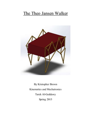
  • 1. The Theo Jansen Walker By Kristopher Brown Kinematics and Mechatronics Tarek Al-Geddawy Spring 2015
  • 2. 1 Table of Contents Introduction................................................................................................2 Mobility......................................................................................................2 Using PDF Resource...................................................................................3 Iteration 1..................................................................................................................3 Simulation for further optimization ..............................................................4 Iteration 2..................................................................................................................4-5 Iteration 3..................................................................................................................6-7 Iteration 4..................................................................................................................7-9 Design Summary ..................................................................................................................9-10 Sensing Objects....................................................................................................................10 Arduino Sketch.........................................................................................................11 Arduino Code ...........................................................................................................12 Conclusion............................................................................................................................12 References............................................................................................................................13
  • 3. 2 Introduction: In this project, I analyzed a four-legged form of the Theo Jansen Walker linkage design. Theo Jansen, the initial inventor of this design, has been creating this type of sustainable kinematic contraptions since 1990. They are referred to as ‘Strandbeests’, because their first existence started on the beach. Their strong characteristic of these walkers is the fact that they do not require any sensors, motors, or other technology to control or power its movements. This report will highlight the design strengths of this beast by showing the motion and kinematic analysis performed by the ‘leg movements’ of the walker when powered by a hypothetical motor. Mobility: To determine the movement and flexibility of this ten linkage design, I performed a mobility analysis using the number of revolute joints and links. This can be seen in figure 1 below. Figure 1: Mobility analysis A mobility of 1 degree of freedom means that this linkage mechanism can be controlled and powered by a single crank. The next step was to determine the right lengths for these links in order to create an ideal motion path for the toe of the walker that both supports the mechanism and allows for contact to the ground at all times. This path can also be referred to as a ‘trace’. The ideal motion trace that I tried to create for this project can be seen below in figure 2. Figure 2: Ideal Trace Goal
  • 4. 3 Using PDF resource: Iteration 1: At first, I used the PDF resource: The Design and Optimization of a Crank-Based Leg Mechanism by Amanda Ghassaei from Pomona College Department of Physics and Astronomy. She recorded the optimized link lengths from Theo Jansen’s book ‘The Great Pretender’. I sketched the diagram in figure 3 below in SolidWorks Assembly Layout feature. Figure 3: 1st iteration using Theo Jansen’s optimized lengths The trace path is also shown in the figure above which is the linear displacement of toe. Although, this design has a great support phase, the transfer phase is not as round as it could be. I also analyzed this design’s linear velocity which can be seen below in figure 4. Figure 4: Linear Velocity (magnitude) for Iteration 1 In figure 5 on the next page, the linear acceleration magnitude for iteration 1 is shown.
  • 5. 4 Figure 5: Linear Acceleration (magnitude) for Iteration 1 Simulation for Further Optimization: Since the optimized links did not have a great transfer phase trace, I decided to use a simulator to develop my own linkage lengths and to see the effects of each length change. The simulator from mekanizmalar.com/theo_jansen.html which can be seen in figure 6 was very helpful in this endeavor. Figure 6: Simulation Second Iteration: For the second iteration design, I decided to make the two pivots on the same axis instead of offset from each other like the first iteration. This helped with rounding out and widening the trace. The lengths of this iteration are much larger in size than the length in the first iteration. The mechanism sketch, linkage lengths, and trace can be seen in figure 7 on the next page.
  • 6. 5 Figure 7: 2nd iteration linkage lengths, trace, and sketch Now that I was able to build a design that made the transfer phase rounder, I sacrificed a near flat support phase. This can be seen by the linear displacement which can be seen in figure 8 below. Figure 8: Linear Displacement of Iteration 2 The linear velocity was analyzed and is shown in figure 9 below. Figure 9: Linear Velocity (magnitude) of Iteration 2 In figure 10 on the next page, the linear acceleration of iteration 2 is shown.
  • 7. 6 Figure 10: Linear Acceleration (magnitude) of Iteration 2 Third Iteration: My goal for my third iteration was to increase the width of the trace in order to create a flatter support phase. I realized that lengthening link numbers 5 and 3 were helpful in doing this. The mechanism sketch, linkage lengths, and trace can be found in figure 11 below. Figure 11: Iteration 3 mechanism sketch and linkage lengths As can be seen from figure 12 below, I was able to change the linear displacement to flatten out both the transfer and support phases. Figure 12: Linear Displacement of Iteration 3 Out of the three iterations, this displacement matches the closest to the ideal trace goal.
  • 8. 7 The linear velocity of iteration 3 was analyzed, which can be seen below in figure 13. Figure 13: Linear Velocity (magnitude) of Iteration 3 The linear acceleration of iteration 3 was analyzed which can be seen below in figure 14. Figure 14: Linear Acceleration (magnitude) of Iteration 3 Iteration 4: After this third iteration, I decided to try and get even closer to the ideal trace by reducing the width of the trace and increasing the height slightly. The length of the 5th link compared to the 4th link was helpful in increasing the height of the trace. A reduction of length for the 12th, 3rd, and the crank links helped with reducing the width of the trace. The mechanism sketch and linkage lengths can be found in figure 15 below. Figure 15: Iteration 4 mechanism sketch and linkage lengths
  • 9. 8 I was successful in reducing the width and increasing the height of the trace to better match the ideal trace goal. The linear displacement of this design can be seen in figure 16 below. Figure 16: Linear Displacement of Iteration 4 The linear velocity of this design was analyzed and can be seen in figure 17 below. Figure 17: Linear Velocity (magnitude) of Iteration 4 The linear acceleration of iteration 4 was also analyzed and is shown below in figure 18. Figure 18: Linear Acceleration (magnitude) of Iteration 4
  • 10. 9 Unfortunately, when I tried to build iteration 4 in SolidWorks using 3D linkages it was not feasible. When rotating the crank in a full revolution, the 7th linkage collides into the 9th linkage. This collision can be seen in figure 19 below. Figure 19: Collision between 7th and 9th linkage Design Summary: Due to the collision of the fourth iteration, I decided to move forward with the third iteration design. My walker design consists of four ‘legs’ made up of 10 individual links each. The links are layered and connected to each other by variable length pegs. This overlapping design can be seen in figure 20 below. Figure 19: Isometric view of leg Figure 20: Layered connection between 4 links As was stated earlier in the report, each leg can be powered by a single crank on each side of the body. The crank highlighted in figure 21 on the next page is attached to a 52” center shaft that is powered by a hypothetical motor.
  • 11. 10 Figure 21: Power crank attached to two legs The cranks on both sides of the body are in a 180 degree phase shift from each other, resulting in the walker’s ability to move forward or backwards while maintaining stability. This walker also has at least two points of contact with the ground at all times which is why the transfer phase is so important. This can be seen in figures 22 and 23. Figure 22: 180 degree shift between cranks Figure 23: Stability with two legs touching ground Sensing Objects: Arduino Sketch: With the hypothetical implementation of two buttons, the walker can determine where objects are relative to its body and perform a direction function for the respective input. Using an
  • 12. 11 Arduino Uno, I created a program that uses three buttons to do three separate functions: turn the motor on/off, move the walker forward, and move the walker backwards. The direction buttons would be on each end of the body and when they are hit by the object, they reverse its current movement. I used ‘Fritzing’ to create a sketch of the circuit layout required to run the program. This layout can be seen in figure 24 below. Figure 24: Arduino Sketch Arduino Code for three button program: const int controlPin1 = 2; // connected to pin 7 on the H-bridge const int controlPin2 = 3; // connected to pin 2 on the H-bridge const int enablePin = 9; // connected to pin 1 on the H-bridge const int directionSwitchPin = 4; // connected to the switch for direction const int rightdirectionSwitchPin =6; const int onOffSwitchStateSwitchPin = 5; // connected to the switch for turning the motor on and off const int potPin = A0; // connected to the potentiometer's output // create some variables to hold values from your inputs int onOffSwitchState = 0; // current state of the On/Off switch int previousOnOffSwitchState = 0; // previous position of the on/off switch int directionSwitchState = 0; // current state of the forward direction switch int rightdirectionSwitchState = 0; //current state of the backward direction switch int previousDirectionSwitchState = 0; // previous state of the forward direction switch int previousrightdirectionSwitchState = 0; // previous state of the backward direction switch int motorEnabled = 0; // Turns the motor on/off int motorSpeed = 0; // speed of the motor int motorDirection = 1; // current direction of the motor void setup(){ // intialize the inputs and outputs pinMode(rightdirectionSwitchPin, INPUT); pinMode(directionSwitchPin, INPUT); pinMode(onOffSwitchStateSwitchPin, INPUT); pinMode(controlPin1, OUTPUT); pinMode(controlPin2, OUTPUT); pinMode(enablePin, OUTPUT); // pull the enable pin LOW to start digitalWrite(enablePin, LOW); } void loop(){ // read the value of the on/off switch onOffSwitchState = digitalRead(onOffSwitchStateSwitchPin);
  • 13. 12 delay(1); // read the value of the direction switch directionSwitchState = digitalRead(directionSwitchPin); rightdirectionSwitchState = digitalRead(rightdirectionSwitchPin); // read the value of the pot and divide by 2 to get // a value that can be used for PWM motorSpeed = analogRead(potPin)/2; // if the on/off button changed state since the last loop() if(onOffSwitchState != previousOnOffSwitchState){ // change the value of motorEnabled if pressed if(onOffSwitchState == HIGH){ motorEnabled = !motorEnabled; } } // if the direction button changed state since the last loop() if (directionSwitchState != previousDirectionSwitchState) { // Move the walker forward if pressed if (directionSwitchState == HIGH) { motorDirection = 1; } } // if the direction button changed state since the last loop() if (rightdirectionSwitchState != previousrightdirectionSwitchState) { //Move the walker backwards if pressed if (rightdirectionSwitchState == HIGH) { motorDirection = 2; } } // change the direction the motor spins by talking // to the control pins on the H-Bridge if (motorDirection == 1) { digitalWrite(controlPin1, HIGH); digitalWrite(controlPin2, LOW); } if (motorDirection == 2) { digitalWrite(controlPin1, LOW); digitalWrite(controlPin2, HIGH); } // if the motor is supposed to be on if (motorEnabled == 1) { // PWM the enable pin to vary the speed analogWrite(enablePin, motorSpeed); } else { // if the motor is not supposed to be on //turn the motor off analogWrite(enablePin, 0); } // save the current On/Offswitch state as the previous previousDirectionSwitchState = directionSwitchState; previousrightdirectionSwitchState = rightdirectionSwitchState; // save the current switch state as the previous previousOnOffSwitchState = onOffSwitchState; } Conclusion: I thought this project was interesting due to the fact that there is not one right answer. Extensive research is being done in the engineering field to find applications for this cutting edge mechanism and it is exciting to look at the
  • 14. 13 mathematical considerations needed to optimize the movement. One of my biggest struggles throughout this assignment was in building the legs and determining the length sizes. It is exciting to see that I was able to use engineering intuition to optimize the trace. I had a goal for each one of my iterations, and it was satisfying to see after many trials I was able to create a trace that closely relates to the ideal trace. A disappointment was that the trace that performed the best was not physically feasible due to collision between the 7th and 9th link. If there was more time to analyze the problem, I would look into if I could develop a different leg assembly to use iteration 4 and avoid the collision problem. Overall, this project exposed me to power that kinematic analysis has on real world applications in engineering.
  • 15. 14 References Jansen, Theo. The Great Pretender. Uitgeverij. 2007. The Design and Optimization of a Crank-Based Leg Mechanism, Pomona College Department of Physics and Astronomy. 2011. PDF file.