EOS Whitepaper - C & A Tool Quality
•
0 gostou•603 visualizações

EOS Whitepaper - C & A Tool Quality

Recomendados
Recomendados
Mais conteúdo relacionado
Mais procurados
Mais procurados (17)
Semelhante a EOS Whitepaper - C & A Tool Quality
Semelhante a EOS Whitepaper - C & A Tool Quality (20)
Mais de Machine Tool Systems Inc.
Mais de Machine Tool Systems Inc. (20)
Último
Último (20)
EOS Whitepaper - C & A Tool Quality
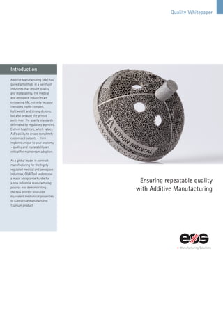
- 1. Quality Whitepaper Ensuring repeatable quality with Additive Manufacturing Additive Manufacturing (AM) has gained a foothold in a variety of industries that require quality and repeatability. The medical and aerospace industries are embracing AM, not only because it enables highly complex, lightweight and strong designs, but also because the printed parts meet the quality standards delineated by regulatory agencies. Even in healthcare, which values AM’s ability to create completely customized outputs – think implants unique to your anatomy – quality and repeatability are critical for mainstream adoption. As a global leader in contract manufacturing for the highly regulated medical and aerospace industries, C&A Tool understood a major acceptance hurdle for a new industrial manufacturing process was demonstrating the new process produced equivalent mechanical properties to subtractive manufactured Titanium product. Introduction
- 2. The Challenge: The lack of understanding regarding quality approach to additive manufacturing remains one of the biggest investment hurdles today – the uncertainty outweighing any benefits of the technology – especially in heavily regulated industries. Therefore, it is incumbent upon the AM industry to highlight the true value of this technology, showing that the quality and repeatability of parts can stand up to quality protocols met by traditional manufacturing standards. Using metal additive manufacturing machines (EOS M290, Krailling, Germany) C&A Tool created a protocol to demonstrate the direct metal laser sintering process could meet or exceed industry standards for mechanical integrity. Using Good Manufacturing Practice (GMP) quality control requirements and ASTM testing methods, C&A Tool created a protocol to challenge additive manufacturing process using critical to quality variables, such as laser power. The goal was to demonstrate the DMLS process meets the appropriate ASTM material acceptance criteria for mechanical testing and part density for Titanium ELI alloy (ASTM F3001). The standard procedures and C&A Tool work instructions utilized in this study are listed in Table 1 & 2. Table 1 Doc. Control # Description ASTM F3001 Additive Manufacturing Titanium-6 Aluminum-4 Vanadium ELI with Powder Bed Fusion ASTM E8/E8M Tension Testing of Metallic Materials ISO 3369 Impermeable sintered metal materials and hardmetals - Determination of density QP 7 Quality Procedure Product Realization QP 8 Quality Procedure Measurement Table 2 Operator Procedures Powder Sieving and Cycle Reclamation File Management M290 Work Instruction Powder Selection Tear Out Powder Removal Validation References/ Applicable Procedures
- 3. Methods Prior to beginning the quality test protocol, C&A Tool created a cause and effect (C&E) study to determine the worst case variables in the process using design of experiments. This initial study considered laser power, heat treatment temperature, and heat treatment time, orientation, position, exposure strategy, and layer thickness as potential critical to quality (CtQ)variables. CtQ Variables Matrix Details: EOS parameter sets include vari- ables such as laser power, layer thickness, and scan strategy. These variables in an EOS parameter set can be varied through program- ing of the EOSPRINT software; however, for production process these parameters must be fixed. Similarly, exposure strategies are controlled by the program sent to the machine. As a result, if the exposure strategy, layer thickness, or parameter set is changed a requalification may be necessary. Laser Power Laser power is controlled by the parameter sets within the exposure strategy of each program sent to the machine. In this study, laser power was monitored during the build and a warning was triggered when the instantaneous laser power went below 4 percent (355 W) of the 370 watts nominal setting. A warning is also triggered if the monitoring device records instantaneous laser power under 5.5 percent (350 W). In this quality protocol, a laser measurement device verified laser power before and after a build. In the cause and effect (C&E) study, two programs were created to produce worst case scenarios in terms of laser power, a critical to quality variable. One program took into account the lowest laser power anticipated (error message at 5.5% laser power degradation) plus the margin of error for the laser measuring equipment. The laser measuring equipment has a margin of error of ± 4%. Therefore, the lowest laser power that the DMLS parts may see is -9.5% (334.85 W). The second program took into account the highest laser power; which accounting for the measurement variation of the laser measuring equipment would be +4% or 384.8 W. Layer Thickness Layer thickness is controlled by the program sent to the machine. In all parameter sets the layer thickness was set to 0.060mm. If the thickness is changed from the 0.060mm setting in this protocol, requalification or justification will be required. Heat Treat The heat treatment will be set and the extremes will be challenged during this protocol. In this in- stance, requalification or justifica- tion will need made if this is changed. Position/Orientation Position or orientation is challenged on all areas of the plate within this protocol as pictured In Figure 1. The results from the C&E study were reviewed and worst case variables were determined to be: • Laser power • Heat treat temperature • Heat treat time Four builds were produced on two different DMLS machines, in the build configuration detailed in Figure 1. Each build comprised tensile test bars and density cubes configured on the build platform to capture potential sources of variation, including location and orientation of the coupon during the build process (Figure 1). Worst case variables of laser power, heat treatment temperature, and heat treatment time found in the C&E study were varied in the four builds. Layer thickness, material (Ti6Al4V ELI, ASTM 3001), exposure strategies, and machining (ASTM E8) remained constant throughout the protocol. Hot Isostatic Pressing (HIP) was not considered in this study. All builds were grown using a parameter matrix, which included: Class A based on ASTM F3001, laser power, layer thickness, material, position/orientation, exposure strategies, heat treat time, and heat treat temperature. A stress relieving heat treatment (Applied Thermal, Warsaw, IN) was performed prior to parts being removed from the platform. Round tensile bars were processed and tested according to ASTM E8 and density cubes were processed and tested according to ISO 3369. Acceptance Criteria It’s important to note that the mechanical properties, chemical properties and density listed in Table 4 are specific to these builds. All builds were tested and evaluated per the following specifications: • Mechanical Properties: Table 3 of ASTM F3001 • Chemical Properties: Table 1 and 2 of ASTM F3001 • Density: ISO3369 In addition to acceptance criteria, Table 3 details average results for all builds showing they meet the standard acceptance criteria for each mechanical property. Quality Protocol Figure 2. Build plate orientation Table 3: Results with acceptance criteria. Titanium 64V - ELI - GRADE 23 Standard Tensile Strength Yield Strength Reduction of Area Elongation Young’s Modulus Hardness Density ASTM F3001-13 125 ksi (860 MPa) 115 ksi (795 MPa) 25% 10% x x x ASTM F136-13 125 ksi (860 MPa) 115 ksi (795 MPa) 25% 10% x x x ASTM B348-13 120 ksi (828 MPa) 110 ksi (759 MPa) 15% 10% x x x C & A Tool Tested Mechanical Properties 156 ksi (1075 Map) 143 ksi (986 Map) 52% 24% 16500 ksi (113.7 Gap) 35 (HRC) 4.42 g/cm3 (99.8%) Figure 1. Test coupon location and orientation on the build platform
- 4. The Figure 3 below detail results for ultimate tensile strength, yield strength, reduction of area, and percent elongation for Class A (ASTM F3001) additive manufactured tensile bars as compared to ASTM F136, standard for surgical implants, ASTM F3001, standard for powder bed fusion, ASTM B348, standard for bars and billets, and ASTM F1108, standard for titanium casting materials. This study clearly demonstrates DMLS process exceeds the relevant standards for all applicable mechanical testing properties as defined by industry accepted standards in medical and aerospace. Capability results can be seen in the Appendix. Test Results and Discussion Figure 3: Mechanical testing results for all group as compared to relevant standards. “These kinds of OQ tests have become an important part of our business. Our findings show what we’ve known all along to be true: AM produced parts not only free engineers from traditional manufacturing and design restraints, but also enable production of high-quality, repeatable parts.” – John Halverson, General Manager of Medical Business Unit C&A Tool Conceptual tibial tray design using Titanium additive manufacturing
- 5. Figure 4: Mechanical properties reported based on location of specimen on build platform. In recent years there has been a greater interest in build location in additive manufactured production. Build location was controlled in this study and the results are shown in Figure 4 below. The data demonstrates that for the EOS M290 DMLS machine using 60 micron layer thickness and the previously described laser power variation, the mechanical strength properties do not vary significantly based on build location (quadrants top left, top right, bottom left, bottom right and middle).
- 6. Similar to the consistent mechanical testing results, density measurements did not vary per machine build location. Another variable of interest is part orientation on the build platform. Figure 6 below demonstrate there is not a significant difference in mechanical properties between horizontal and vertical built test specimens (ASTM E8) Figure 5: Density measurements reported based on location of specimen on build platform. Figure 6: Mechanical properties reported based on build orientation on the build platform. Critical to quality variables of laser power, build location, build orientation, and heat treatment temperatures were challenged in this protocol. The results clearly demonstrate direct metal laser sintering can meet or exceed industry standards for mechanical integrity and part density does not vary across the build platform. Ensuring quality protocols will continue to be essential to driving widespread adoption of additive manufacturing, Conclusion especially in the more heavily regulated industries like medical, aerospace and automotive. As a result, the AM industry must continue to prioritize this type of QP testing as completed by C&A Tool. The outcomes embolden the AM industry to take on quality skeptics with compliant data demonstrating the value of EOS solutions to produce the highest quality parts.
- 7. Think the impossible. You can get it. EOS GmbH Electro Optical Systems Corporate Headquarters Robert-Stirling-Ring 1 82152 Krailling/Munich Germany Phone +49 89 893 36-0 Fax +49 89 893 36-285 Further EOS Offices EOS France Phone +33 437 49 76 76 EOS India Phone +91 44 39 64 80 00 EOS Italy Phone +39 02 33 40 16 59 EOS Korea Phone +82 32 552 82 31 EOS Nordic & Baltic Phone +46 31 760 46 40 EOS of North America Phone +1 248 306 01 43 EOS Singapore Phone +65 6430 05 50 EOS Greater China Phone + 86 21 602307 00 EOS UK Phone +44 1926 62 31 07 www.eos.info • info@eos.info Status 5/2017. Technical data subject to change without notice. EOS is certified according to ISO 9001.