The Power house complex of Karuma Hydropower project comprises three main caverns i.e Power house, Transformer Hall and Tailrace surge gallery set at a depth of about 80m in mainly granitic gneiss rock medium. The cavern has been oriented in a N141° direction based on engineering considerations. The principle stress direction is also found nearly parallel to the axis of the caverns and thus the present orientation satisfies both engineering and geotechnical criteria. The support by way of rock anchors and SFRS/ Plain shotcrete has been provided based on analysis using phase 2 software. The underground caverns lie in low geostress field and therefore numerical simulation of excavation of these caverns were done to understand the rock mass behavior during excavation and thus help in design of excavation sequence and rock support. The excavation of all three caverns has since been completed and concrete works are in progress. This paper sums up the 3D simulation analysis of the rock medium and the proposed rock support system for the three caverns.
(ANVI) Koregaon Park Call Girls Just Call 7001035870 [ Cash on Delivery ] Pun...
Analysis and Design Aspects of Support Measures of Main Caverns of Karuma Hydropower Project, Uganda
1. IOSR Journal of Mechanical and Civil Engineering (IOSR-JMCE)
e-ISSN: 2278-1684,p-ISSN: 2320-334X, Volume 14, Issue 1 Ver. VI (Jan. - Feb. 2017), PP 08-13
www.iosrjournals.org
DOI: 10.9790/1684-1401060813 www.iosrjournals.org 8 | Page
Analysis and Design Aspects of Support Measures of Main
Caverns of Karuma Hydropower Project, Uganda
B K Ojha
Ex-Project Director, EIPL
Abstract: The Power house complex of Karuma Hydropower project comprises three main caverns i.e Power
house, Transformer Hall and Tailrace surge gallery set at a depth of about 80m in mainly granitic gneiss rock
medium. The cavern has been oriented in a N141° direction based on engineering considerations. The principle
stress direction is also found nearly parallel to the axis of the caverns and thus the present orientation satisfies
both engineering and geotechnical criteria. The support by way of rock anchors and SFRS/ Plain shotcrete has
been provided based on analysis using phase 2 software. The underground caverns lie in low geostress field and
therefore numerical simulation of excavation of these caverns were done to understand the rock mass behavior
during excavation and thus help in design of excavation sequence and rock support. The excavation of all three
caverns has since been completed and concrete works are in progress. This paper sums up the 3D simulation
analysis of the rock medium and the proposed rock support system for the three caverns.
I. Introduction
The Karuma Hydropower project is a run of the river scheme located on Nile river in the Northern
district about 270 Km of Kampala, the capital city of Republic of Uganda. The project envisages the
construction of 14m high concrete dam, 6nos, 20m high tower type power intake and 7.7m diameter headrace
tunnel to carry 1048 cumecs of design discharge to feed 6x 100MW of Francis turbines- generators to generate
600MW of power. The power house complex consist of three parallel large caverns i.e. 200m (L)x 21.3m (w) x
53m (H)- Power house cavern, 161m (L) x 14.7m(W) x 18.5/32.50m (H) transformer cavern and 314m(L)x
21.50m (W)x 50m (H) twin restricted orifice type tailrace surge chamber. The water is taken back to the river
through 12.9m finished diameter, bottom flat horse shoe shaped and 8.6 Km and 8.7 Km long twin tail race
tunnels. The rock bolt crane girder has been designed for the EOT crane beam in view of good rock mass
condition. The reinforced concrete beam of the Rock bolt crane girder is anchored to the rock wall of the power
house cavern with bolts so that the loads are jointly shared by the RCC, bolts and surrounding rocks. The Power
House Complex is hardly 200m away from the river bank and is housed in a shallow rock cover. Excavations of
these three caverns have been completed through granitic gneiss and the geological features encountered have
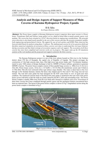
been on expected lines. The layout of the power house complex is shown in Fig 1 longitudinal section along the
power house complex is furnished in Fig 2.
Fig 1: Layout of Power House Complex
2. Analysis and Design Aspects of Support Measures of Main Caverns of Karuma Hydropower ..
DOI: 10.9790/1684-1401060813 www.iosrjournals.org 9 | Page
Fig 2
II. Geological Set-up
The rock type exposed in the project site comprise of granite gneiss including biotite gneiss
amphibolites gneiss and amphibolites. The exploration of the rock mass around power house was done by
excavating drift and drill holes. The surrounding rocks in the underground powerhouse site is slightly weathered
granitic gneiss, amphibolite gneiss, and amphibolites with integrated rock mass, the tendency of the gneissic
schistosity is substantially perpendicular to the cavern axis. The underground powerhouse mainly is in class II
rock class and the caverns is very stable as a whole.
The rock mass is dissected by four sets of geological discontinuities. The four set of joints developed are:
S1 (Foliation Joint) with altitude 125-140° / 75-80°, persistence is very high (720m), with spacing 2 to 6m.
S2: with altitude 160-175°/ 55-70° persistence is low to medium (2-5m), with spacing 0.5 to 0.6m
S3: with altitude 340-355°/ 75-85°, persistence is high (>20m), with spacing 0.5 to 0.6
S4 with altitude 005-015°/ 55-70°, persistence is low (1-3m) and is discontinuous developed, with 0.5 to
3m.
The joints are tight and are rough planar. However it is found that four sets of joints do not appear at the same
place and 1 or 2 sets of joints appear within the same section.
III. Cavern Orientation
The underground complex has been designed with power house transformer cavern and twin tailrace
surge gallery with depth of cover in the range of 80m from the surface. These caverns are parallel to each other
with 40m of rock pillar between power house and Transformer cavern and 119m between Transformer cavern
and Tail Race Surge Chamber. Main consideration in orienting the cavern is to make longitudinal axis
perpendicular to the strikes of the faults and joints are parallel to the direction of the maximum rock stress and at
the same time to ensure that the layout fits well with the orientation of the water conductor system. In the
present case the caverns have been oriented N39° W-S39° E tentatively in line with the geotechnical
consideration and matching the layout of the water conductor system. The thickness of the overlaying rock mass
on the underground powerhouse and transformer room is about 40-50m (1.9 to 2.38 times of the cavern
diameter), while that on the tailrace surge chamber is about 32-44m (1.52 to 2 times of the cavern diameter),
which can basically meet the requirements of the 1.5 to 2.0 times of overlying rock mass thickness. According
to the engineering experience, because of less rock cover, proper precaution is required on the excavation
sequence and rock support measures as well as monitoring of the rock deformation.
The gneissesity attitude of power house is N35-50°E SE < 75-80° and the welding between gneissosity is firm.
The underground powerhouse axis has an angle of 64 ~ 90 °with the foliation strike, which is favorable for the
excavation of underground caverns.
There is an angle of 34~41° between the joints of N78~88°W NE< 75~85° and the cavern axis strike.
The joints of N15~33°W NE < 75~85° is approximately parallel to the cavern axis but have no influence on the
stability of cavern roof, because the two sets of joints are usually closed and steep- dip. The joints of N
73~82°W SW< 45~65° and foliation with moderate- dip angle are easy to form unstable random block at the
roof with random joints, so the systematic support is provided.
In the side wall, there is an angle of 64 ~ 90°between the powerhouse axis and foliation strike, while the dip
angle is mainly 10~30°.The foliation is easy to form unstable blocks with random joints on sidewall, and hence
systematic support measure are provided The structural plane stereographic projection result is shown in Fig 3.
3. Analysis and Design Aspects of Support Measures of Main Caverns of Karuma Hydropower ..
DOI: 10.9790/1684-1401060813 www.iosrjournals.org 10 | Page
Fig 3. Stereographic projection of powerhouse sidewall
During the excavation it was observed that the lithology is mainly slightly newly weathered granitic
gneiss intercalated with a small amount of biotite gneiss and amphibole gneiss. The rock is hard and rock mass
is intact to relatively intact. The RQD is ranging from 85-95%. Generally 1-2 sets of structural planes are
developed with close combination in between. Weathering condition is generally unweathered to slightly
weathered. Ground condition is dry to damp. The RMR values vary between 65~72 and Q value ranging from
14-28 and thus rock mass is generally of class II. However in a length of 10m at RD 152~142, where the rock
mass condition is fair(class-III) with RMR value 41 and Q value 0.92. In this stretch a shear zone of thickness
0.5-0.7m is exposed along foliation with attitude 118-122°/63 − 69°. Maximum thickness of fault is 0.85m,
filling is white plagioclase with crushed rock blocks and a little sand and gravel. The fault is exposed on the
crown area and on the downstream wall but no trace of fault is found on the upstream wall in the 2ndbench
excavation. A patch of Amphibolite 18-20m wide is present from RD 0+00m to 0+20m encountered in the 2nd
bench excavation. In this stretch although the rock mass conditions are good (class-II) but the area is moderately
to highly jointed and orientation of these joints facilitated the plane and wedge failures in the excavation of slant
portion for crane beam.
IV. In-situ Stress
The In-situ stress is a key input parameter in understanding the rock mass behavior and in design of
rock support for the caverns. Analyses carried out by way of numerical models indicate that the rock behavior is
influenced significantly by the state of in-situ stress especially the horizontal to vertical stress ratio. The values
obtained from the hydro fracturing tests conducted in the two exploratory drill holes in power house indicated
a) Maximum horizontal principle stress as 3.05~8.89 Mpa
b) Minimum horizontal principal stress 2.63~6.23 Mpa
c) Direction of maximum horizontal principal stress N55°- 62° E which is almost parallel to the rock mass
gneissosity.
The stress measurements are identically consistent with the regional stress field and the horizontal
tectonic stress is dominant in underground powerhouse area. The horizontal stress ratio is about 0.71-0.82 and
the maximum horizontal principal stress is in the direction of N56°-N60° and thus the power house complex
belongs to the low-stress area. The strength-stress ratio is 4.7-6.9, more than 4 and thus the in-situ stress has an
exiguity influence on the surrounding rock. During the excavation of caverns no high geostress problems such
as rock spalling and peeling off were observed which only indicates that the strength –stress ratio of surrounding
rocks within the powerhouse area is relatively high and geostress has hardly an impact on the stability of
surrounding rock mass.
V. 3d Simulation Analysis
The numerical analysis using finite difference element FLAC3D was carried out considering the
surrounding rocks around caverns as perfectly plastic, homogeneous and isotropic medium. The numerical study
was based on the Mohr-Coulomb failure criterion which gives a very simple solution for the progressive failure
of the rock mass surrounding the cavern. The numerical simulation was carried out to understand the
deformation behavior of surrounding rock medium during excavation, the buckling failure mode of rocks
mechanical behavior and thus assist in designing the rock support system for the caverns. Based on results of
many field and laboratory tests combined with similar projects experiences following rock properties have been
used in the analysis.
4. Analysis and Design Aspects of Support Measures of Main Caverns of Karuma Hydropower ..
DOI: 10.9790/1684-1401060813 www.iosrjournals.org 11 | Page
Fig 4. Model of underground Caverns
Table-1. Rock parameters
Rock Mass
Classification
Degree of Weathering Volume Weight
(kN/m3
)
Poisson
Ratio
Modulus of
Deformation
(Gpa)
Shearing Strength
f’ C’
(Mpa)
II Slightly weathered or fresh 26.5 0.185 14 1.15 1.6
III Lower section of moderately
weathered
26 0.215 7 0.95 1.05
IV Highly Weathered 24 0.275 2 0.55 0.35
The influence of stress contours of one cavern over others and to calculate stresses and displacements
around underground excavations, the finite difference element was carried out on FLAC 3D to simulate the
actual excavation process of underground caverns and obtain displacement, stress field and plastic zone during
the stage wise excavation of surrounding rocks around powerhouse caverns and the result of analysis is
furnished in table -2 The excavation responses for the powerhouses and the main transformer cavern are
respectively analyzed as follows:
5.1 Rock Mass Deformation
Since the underground powerhouse is horizontal tectonic stress based and the rock cover being not very
high, the sidewall deformation is greater than the crown arch deformation. After the cavern excavation, the
maximum deformation of the powerhouse crown works to about 5mm but increases to 12mm in the main
transformer cavern crown due to the caverns effect. The maximum deformation of the surge chamber cavern
crown arch is about 6mm and the cavern bottom floor indicates rebound relaxation deformation of about 12mm.
The high sidewall effect is significant at the powerhouse cavern showing a deformation to the tune of 35-
40mm in the upstream side wall and 40-50mm in the downstream sidewall. . The sidewall deformation at the
main transformer cavern is less than that at the powerhouse, with the maximum deformation of about 12 ~
15mm. The maximum deformation of the powerhouse end wall is about 12~16mm, and the end wall
displacement of the transformer cavern is about 8~ 12mm. The maximum deformation of upstream sidewall of
surge chamber is about 35 ~40mm, and the maximum deformation of downstream sidewall is about 40~45mm.
The rock mass deformation was monitored in all the three caverns by way of 4–point Bore-hole
extensometers. The instruments exhibited better rock mass behavior with maximum displacement of less than
3mm in all the three caverns except the downstream wall near bus duct junction with a cumulative displacement
of 6.69 mm during the excavation period.
5.2 Rock Stress
The rock stress field indicates significant changes after excavation. Since this zone is controlled by the
regional horizontal tectonic stress field, the crown arch at the powerhouses , the main transformer cavern and
surge chamber exhibits significant stress concentration with the maximum compressive stress of about 10~
12MPa. The stress at the powerhouse machine hall reaches to the maximum compressive stress of about 15MPa.
As the large structural face nearby the caverns is absent and the stress relaxation at the surrounding caverns is
uniformly distributed, the stress relaxation at upstream and downstream high sidewall is quite conspicuous with
the minimum principal stress being in the range of about 1~3MPa.
5. Analysis and Design Aspects of Support Measures of Main Caverns of Karuma Hydropower ..
DOI: 10.9790/1684-1401060813 www.iosrjournals.org 12 | Page
5.3 Rock’s Plastic Zone
The thickness of rock pillar’s plastic zone is much larger between the powerhouse and the main
transformer cavern, but there are still large elastic rock pillars between the two. The thickness of rock pillar’s
plastic zone is very large between the main transformer cavern and surge chamber.
Analyzing the extent of surrounding rock’s plastic zone distribution for the caverns after the excavations,
powerhouse crown shows with plastic zone at an depth of1~3m where as the high side walls experiences rock’s
plastic zone up to a depth of about 4~8m . Main transformer cavern crown with plastic zone at a depth of 1 ~
2m, the side wall rock is about 3 ~ 5m depth. Surge chamber crown with plastic zone at an ordinary depth of 1 ~
2m, the side wall rock in general is about 4~8m depth.
The Response statistics of Underground caverns is furnished in Table-2
Table 2
Cavern
Excavation response. Power House
Transformer Cavern Surge chamber
Deformation (mm) Top Arch 5 12 6
Si de Wall 40~50 12~15 40~45
Plastic Zone (m)
Top Arch 1~3 1~2 1~2
Si de Wall 4~8 3~5 4~8
The first principal stress
(MPa)
Top Arch -8~-12 -6~-8 -6~-10
Si de Wall -2~-4 -2~-4 -2~-4
The third Principal stress
(MPa)
Top Arch -1~-3 -1~-2 -1~-2
Si de Wall -1~-0.2 -0.5~0 -1~-0.1
The buried depth of the caverns has been shallow and vertical geostress is small. Controlled by the
horizontal principle stress, the rock mass of the cavern crown arch has good stability. The high sidewall effect is
dominant at the main power house and tailrace surge cavern but the local tensile stress has not exceeded the rock
tensile strength, and the relaxation depth of the side wall is relatively higher and hence timely installation of
support is paramount.
VI. Rock Support Measures
The rock support system has been designed as per rock mass classification parameters and in line with
the analysis of surrounding rock stability. The rock support measures for the three caverns were studied by 3D
simulation analysis. As per the recommendations made by Grimstad and Barton (1993), the spacing, number
and strength of rocks bolts and shotcrete thickness requirement depends on rock mass quality Q and span of the
cavity as shown in fig-3. The permanent support in the form of rock anchors and shortcrete were proposed based
on geological underground powerhouse of surrounding rock Q value = 28, cavern span 19.6m, Excavation
support ratio (ESR)= 1.0 as per Fig -5 below:
Fig 5: Q classification –Permanent Support Reccomendation (Grimstad& Barton, 1993)
6. Analysis and Design Aspects of Support Measures of Main Caverns of Karuma Hydropower ..
DOI: 10.9790/1684-1401060813 www.iosrjournals.org 13 | Page
Similarly for Transformer cavern with span 14.7m and ESR=1.0, the corresponding support was
worked out and for Tail Race Surge gallery with a span of 22.8m and ESR=1.0,the corresponding support
measures were calculated as shown in fig.3. Since the high side wall effect is significant in Surge Chamber and
maximum displacement reaches 42mm at the waist of side walls , the rock support design has been given due
attention. The rock support as finalized for the three caverns is furnished in Table 3.
Table-3. Support measures for Caverns.
Cavity Roof Walls
P.H Cavern
150mm thick SFRS and 6m to 9m long 28mm
diameter grouted rock anchor @ 1.5m c/c
150mm thick plain shotcrete , 25 diameter 6m/9m
long grouted rock anchor @ 1.50m𝖼/c.
Transformer cavern
120mm thick shotcrete 25 diameter 6m long
rock anchor cement grouted @ 1.5m c/c.
120mm thick shortcrete 25 diameter 6m long
rock anchor cement grouted @ 1.5m c/c.
Tail race surge
chamber
150mm thick SFRS 28 mm diameter 6m / 9.0m
long grouted rock anchor
150mm thick SFRS 28 mm diameter 6m / 9.0m
long grouted rock anchor
Since there shall be water level fluctuation in this Surge Chamber 40 cm thick reinforced concrete
lining is being provided on the walls of the surge cavern. The rock anchors as provided in the side walls shall be
connected with lining reinforcement mesh to provide additional safety of the wall. The caverns are being
monitored by way of 4-point multi- point borehole extensometer (MPBX), anchor stress meters and these
instruments have shown stable trend during the excavation process.
VII. Conclusion
The orientation of the longer axes of the power house, transformer cavern and TRT surge chamber was
finalized to suit the water conductor system and also meeting the requirement of the joint pattern and principal
stress direction. The stability estimation by numerical analysis showed that the total displacements and yielding
zones were drastically reduced after rock reinforcements. The rock mass and the geological discontinuities
encountered in the caverns were on the predicted lines and excavation of the caverns has been completed and
was a smooth affair. The instruments indicated rock mass deformations well within designed values.
Acknowledgement
The author is thankful to Ministry of Energy and Mineral Development (MEMD), UEGCL of Govt. of Uganda
and Sinohydro, and Hydrochina Huadong Corporation, China for cooperation during fieldwork and for the
studies and data compilation.
Reference
[1]. Basic Design Report and unpublished technical reports of Karuma HPP-Hydrochina Huadong corporation, China
[2]. GB 50287-2006: Code for hydropower engineering geological investigation, P R China.
[3]. EM1110-2-2901, Engineering design of Tunnels and Shafts in Rocks, May 1997 by US Army corps of Engineers.
[4]. Support of Underground Excavations in Hard rock by Evert Hoek.
[5]. Barton N; Lien R. and Lunde J. 1974. Engineering classification of Rock Mass for the Design of Tunnel Support. Journal of Rock
Mechanics Volume 6.
[6]. Bieniawski Z T.1992. Design Methodology in Rock Engineering. Balkema, Rotterdam
[7]. PRC 2008. Specification for design of Hydraulic Tunnels, Electric power Industry Standards,
[8]. Grimstand, E; and Barton, N; Updating of the Q system for NMT, Proceedings of the International Symposium on sprayed Concrete
Modern use of Wet Mix Sprayed Concrete for Underground Support, Fagernes, Norway, 1993.
[9]. Central Board of Irrigation and Power, Manual on Planning and Design of Hydraulic Tunnels, Publication no:178, New Delhi,
1984.
Brajesh Kumar Ojha “FIE”,
Graduated in Civil Engineering from Bhagalpur University Bihar in 1984 and joined
National Hydro Electric Power Corporation (NHPC) a Govt. of India Enterprise in Feb
1985. He worked as Engineer to Chief Engineer in NHPC for more than 23 years. He has
wide experience in design & construction of Hydo-projects mainly being Teesta Stage V
(510 MW) HE Project (NHPC) and Teesta Stage VI (500MW) HE Project( Lanco
Infratech Limited) and Teesta III HE project (1200MW) in Sikkim. He has worked as
Owner’s Engineer(EIPL) for Govt. of Uganda for Karuma hydropower project (600MW)
in North Uganda during 2015-16. He is a life member of Tunneling Association of India (TAI), INHA and
ISRM and is a certified Chartered Engineer (India). He has more than twenty publications in national &
international journals and conferences.