
Recomendados
Recomendados
Mais conteúdo relacionado
Mais procurados
Mais procurados (19)
Destaque
Destaque (20)
Semelhante a Paper id 2720147
Semelhante a Paper id 2720147 (20)
Mais de IJRAT
Último
Último (20)
Paper id 2720147
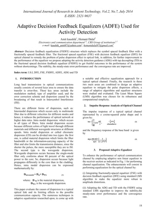
- 1. International Journal of Research in Advent Technology, Vol.2, No.7, July 2014 E-ISSN: 2321-9637 18 Adaptive Decision Feedback Equalizers (ADFE) Used for Activity Detection Amit kaushik1, Hemant Dalal2 Electronics and communication department1,2, CBS Group of institutions1,2 e-mail: kaushik_amit87@yahoo.com1, hemantdalal87@gmail.com2 Abstract- Decision feedback equalization (FSDFE) structure which replaces the symbol spaced feedback filter with a fractionally spaced feedback filter. The fractional spaced equalizer (FSE) with decision feedback equalizer (DFE) for optical channel to remedy the problem of pulse dispersion effect in optical link, in addition, for further improvement in the performance of the equalizer we propose adopting the activity detection guidance (ADG) with tap decoupling (TD) in the fractional spaced decision feedback equalizer (FSDFE) to get fruitful outcomes in the performance of the system without shortcomings. The stability, the steady-state error performance and the convergence rate are improved. Index term: I.S.I, DFE, FSE, FSDFE, ADFE, ADG and TD 1. INTRODUCTION Long haul transmission in optical communications usually consists of several keys area to ensure the data transfer is error-free. These key areas include the modulation method, type of amplifier used, and the error correction scheme and dispersion caused by the broadening of that result in Intersymbol Interference (ISI). There are different forms of dispersion, such as: Intermodal dispersion which occurs only in multimode fiber due to different velocities for different modes and hence, it reduces the performance of optical network at higher data rates. Intra modal dispersion: which occurs in all types of fibers. Intra modal dispersion occurs because different colors of light travel through different materials and different waveguide structures at different speeds. Intra modal dispersion or called chromatic dispersion (CD) can be divided into two types: the first one, is called material dispersion which limits the fiber bandwidth or the information-carrying capacity of the fiber and also limits the transmission distance, since the shorter the pulses, the more susceptible they are to lSI. The second type is the waveguide dispersion. Waveguide dispersion occurs because the single-mode fiber only conforms about 80 percent of the optical power to the core. So, dispersion occurs because light propagates differently in the core than in the cladding. Hence, intra modal dispersion can be expressed mathematically by: Dintramodal = Dm+ DWG (1) where: D M is the material dispersion, DWG is the waveguide dispersion. This paper evaluate the causes of dispersion in a typical optical link and its limiting effects to the possible communication capacity. The numerous techniques in adaptive equalization researched upon, to come up with a suitable and effective equalization approach for a typical optical channel. Finally, the research in these two main areas are combined to design an adaptive equalizer to mitigate the pulse dispersion effects, a range of adaptive algorithms and equalizer structures were studied and evaluated. The Least Mean Square (LMS) algorithm was chosen for its robustness and computational simplicity. 2. Impulse Response Analysis of Optical Channel The impulse response of a typical optical channel represented by a cosine-squared pulse shape and is given by: h(t) = , cos2
- 2. (2) and the frequency response of the base band is given by H(f)= (3) 3. Proposed Adaptive Equalizer To enhance the performance of optical communication channel by employing adaptive non linear equalizer in the receiver section as indicated in Fig. 1 for performing channel equalization. The enhancements will consist in performing equalization for the optical channel by: (i) Integrating fractionally-spaced equalizer (FSE) with decision feedback equalizer (DFE) using standard LMS algorithm to make the equalizer more robust to amplitude distortions. (ii) Adopting the ADG and TD with the FSDFE using standard LMS algorithm to improve the stability,the steady-state error performance and the convergence rate.
- 3. International Journal of Research in Advent Technology, Vol.2, No.7, July 2014 E-ISSN: 2321-9637 (ik) is the previous decision made on the detected , must be above a certain threshold. 19 The principles of adaptive equalizer in [2] have been exploited to compensate the dispersion in optical channel, it allows for longer haul communication before a repeater, the benefits to reduce equipment cost for optical communication link. Concerning the adaptive algorithms, there are several numbers of adaptive algorithms, The least mean squares (LMS) error algorithm and recursive least squares (RLS) algorithm. Each one has its own unique properties and applications. In this paper, we will use LMS only where it is privileged by its simplicity and robustness to signal statistics. The criterion used in the adaptive LMS algorithm is the minimization of the mean square error (MSE) [16] for the N-taps adaptive transversal filter and the output is given by: y(n)=Σ () # ( − !) $% (4) where x(n) is the filter input, d(n) is the desired output and y(n) is the filter output. The filter tap weights are indicated to be functions of time, n, which are time varying and continuously being adapted so that any variations in the channel can be tracked. So, the prediction error is given by: e (n) = desired output -filter output e (n) =d(n)-y(n) (5) Fractionally-Spaced Equalizer (FSE) Fractionally Spaced Equalizer (FSE), which is based on sampling the incoming signal at least as fast as the Nyquist rate. Fractionally-spaced equalizers have taps that are spaced closer than conventional adaptive equalizers, and with a sufficient number of taps, it is almost independent of the channel delay distortion. It means that the equalizer can negate the channel distortion without enhancing the noise (R. D. Gitlin, et al. 1981). Combination of the DFE with FSE technique, we can expect an equalizer with the following qualities: 1. Minimize noise enhancement. 2. Excellent amplitude distortion performance. Decision Feedback Equalizer In a Decision Feedback Equalizer, both the feed forward and feedback filters are essentially linear filters. DFE used for over linear equalizer because latter’s performance in channel that exhibit nulls is not effective. In contrast, the decision feedback equalizer has zero noise enhancements in the feedback loop. The above DFE structure has N 1 + N 2 + 1 feed forward taps and N 3 feedback taps. [2] The output of the equalizer is given by: ^=Σ ) ∗ ' +, $+- .' Σ / +, $# ' (6) where is the tap gain and y*nc n is the input for the forward filter,is the tap gain for the feedback filter and dFi* i signal. The detection of the ‘active’ taps of a time-invariant channel is governed by the equation (John Homer, et al. 1998): )', = (0 1Σ 2.4-5670 1- 80 ), 0 Σ , 180 1- (4-5670)(7) where i=time index, k=tap index, and N is the number of input samples. C k is known as the activity measure. In order to determine a tap to be active, the value of the activity measure, C k This activity threshold is given by: 9:,+ Σ (2),.= () + $# (8) Modifications to the activity measure have to be made to reduce the tap coupling effect (John Homer, et al. 1998). 99' =Σ [(2 @2-AB64-5670).(C-5670)], Σ (C-5670), 1- 80 + $# (9) 4. SIMULATION RESULTS AND DISCUSSIONS FSDFE using standard LMS algorithm. It is clear that the simulated impulse response is resemble a cosine-square shape and having a total of 7- taps. The feed forward section has a total of 6-taps, the first tap has a magnitude of I and the fourth tap has a magnitude of 0.8. The rest of the taps are in active or zero except for tap 7, which is the feedback tap with a magnitude of 1. On the other hand, for the estimated channel impulse response we have run the equalizer for 30000 sample inputs in order to achieve an impulse response in close proximity to the actual simulated channel. It is clear that the channel bears a fair resemblance of the simulated channel. Fig. 1: Impulse response for FSDFE after simulation
- 4. International Journal of Research in Advent Technology, Vol.2, No.7, July 2014 E-ISSN: 2321-9637 20 Fig. 2 Impulse response for FSDFE estimated channel Fig. 3: Impulse response for FSDFE in 3D after Simulation. Fig. 4: Impulse response for FSDFE in 3D estimated channel. Fig. 5: Input to channel and output of equalizer differences for FSDFE. Performance Evaluation for FSDFE with ADG and Tap Decoupling. We have noticed that the inactive taps in the estimated channel were not estimated at zero Adopting ADG with FSDFE could improve the convergence rate and asymptotic performance, detect the non active taps, disregard them in the calculation of the tap weight adoption and set them to zero. However, the true number of active taps cannot be detected accurately and the inactive taps will still suffer from the noisy estimates that are common in any communication channel. The inability to detect the true number of active taps accurately is due to the correlation within the input signal that is causing the coupling amongst the output of the unknown channel.
- 5. International Journal of Research in Advent Technology, Vol.2, No.7, July 2014 E-ISSN: 2321-9637 21 Fig.6: Impulse response in 3D after simulation. Fig.7: Impulse response in 3D estimated channel. Fig.8: Equalizers output 5. CONCLUSION Develop a suitable adaptive equalization technique to mitigate the effects of ISI and dispersion in a typical optical communication channel. With the successful development of the adaptive modified Decision Feedback Equalizer with activity detection guidance and tap decoupling. Least Mean Square (LMS) technique, using stochastic gradient adaptation. This led to a faster convergence rate and better asymptotic performance as shown clearly. The successful implementation of an adaptive modified Decision Feedback Equalizer with ADG and TD in a typical optical communication channel. REFERENCES [1] Theodore S. Rappaport, “Wireless Communications – Principles and Practice” 2 nd edition, Prentice Hall Communications Engineering and Emerging Technologies Series, Upper Saddle River, New Jersey, 2002. [2] B.L.Kaspers, “Equalization of Multimode Optical Fiber Systems”, Bell System Technical Journal, September 1982. [3] John M. Senior, Optical Fiber Communications - Principles and Practice 2nd edition, Prentice Hall International Series in Optoelectronics, New York, 1 992. [4]S.D. Personick, Time dispersion in dielectric waveguides, Bell Syst. Tech. J., 50(3), pp. 843-859, 1 971 . [5] Simon Haykin, Adaptive filter theory, Prentice- Hall, Upper Saddle River, N.J, 1 996 [6] John Homer, Iven Mareels, Robert R. Bitmead, Bo Wahlberg and Fredrik Gustafsson, “LMS Estimation via Structural Detection”, IEEE Transactions on signal processing, Vol. 46, No. 10, October 1998.