Design & Optimization of Equipment for Insertion of Tube Bundle of Heat Exchanger

International Journal of Modern Engineering Research (IJMER) is Peer reviewed, online Journal. It serves as an international archival forum of scholarly research related to engineering and science education. International Journal of Modern Engineering Research (IJMER) covers all the fields of engineering and science: Electrical Engineering, Mechanical Engineering, Civil Engineering, Chemical Engineering, Computer Engineering, Agricultural Engineering, Aerospace Engineering, Thermodynamics, Structural Engineering, Control Engineering, Robotics, Mechatronics, Fluid Mechanics, Nanotechnology, Simulators, Web-based Learning, Remote Laboratories, Engineering Design Methods, Education Research, Students' Satisfaction and Motivation, Global Projects, and Assessment…. And many more.

Recomendados
Recomendados
Mais conteúdo relacionado
Mais procurados
Mais procurados (20)
Destaque
Destaque (20)
Semelhante a Design & Optimization of Equipment for Insertion of Tube Bundle of Heat Exchanger
Semelhante a Design & Optimization of Equipment for Insertion of Tube Bundle of Heat Exchanger (20)
Mais de IJMER
Mais de IJMER (20)
Último
Último (20)
Design & Optimization of Equipment for Insertion of Tube Bundle of Heat Exchanger
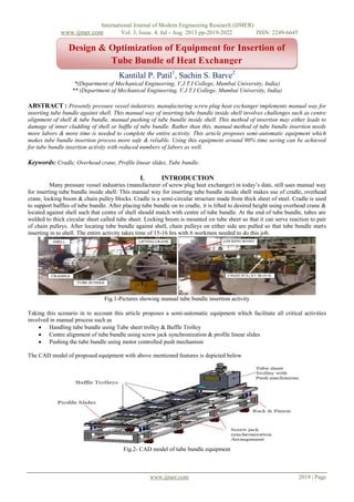
- 1. International Journal of Modern Engineering Research (IJMER) www.ijmer.com Vol. 3, Issue. 4, Jul - Aug. 2013 pp-2019-2022 ISSN: 2249-6645 www.ijmer.com 2019 | Page Kantilal P. Patil1 , Sachin S. Barve2 *(Department of Mechanical Engineering, V.J.T.I College, Mumbai University, India) ** (Department of Mechanical Engineering, V.J.T.I College, Mumbai University, India) ABSTRACT : Presently pressure vessel industries, manufacturing screw plug heat exchanger implements manual way for inserting tube bundle against shell. This manual way of inserting tube bundle inside shell involves challenges such as centre alignment of shell & tube bundle, manual pushing of tube bundle inside shell. This method of insertion may either leads to damage of inner cladding of shell or baffle of tube bundle. Rather than this, manual method of tube bundle insertion needs more labors & more time is needed to complete the entire activity. This article proposes semi-automatic equipment which makes tube bundle insertion process more safe & reliable. Using this equipment around 90% time saving can be achieved for tube bundle insertion activity with reduced numbers of labors as well. Keywords: Cradle, Overhead crane, Profile linear slides, Tube bundle. I. INTRODUCTION Many pressure vessel industries (manufacturer of screw plug heat exchanger) in today’s date, still uses manual way for inserting tube bundle inside shell. This manual way for inserting tube bundle inside shell makes use of cradle, overhead crane, locking boom & chain pulley blocks. Cradle is a semi-circular structure made from thick sheet of steel. Cradle is used to support baffles of tube bundle. After placing tube bundle on to cradle, it is lifted to desired height using overhead crane & located against shell such that centre of shell should match with centre of tube bundle. At the end of tube bundle, tubes are welded to thick circular sheet called tube sheet. Locking boom is mounted on tube sheet so that it can serve reaction to pair of chain pulleys. After locating tube bundle against shell, chain pulleys on either side are pulled so that tube bundle starts inserting in to shell. The entire activity takes time of 15-16 hrs with 6 workmen needed to do this job. Fig.1-Pictures showing manual tube bundle insertion activity Taking this scenario in to account this article proposes a semi-automatic equipment which facilitate all critical activities involved in manual process such as Handling tube bundle using Tube sheet trolley & Baffle Trolley Centre alignment of tube bundle using screw jack synchronization & profile linear slides Pushing the tube bundle using motor controlled push mechanism The CAD model of proposed equipment with above mentioned features is depicted below Fig.2- CAD model of tube bundle equipment Design & Optimization of Equipment for Insertion of Tube Bundle of Heat Exchanger 0 20 40 60 80 100 1st Qtr 2nd Qtr 3rd Qtr 4th Qtr East West North
- 2. International Journal of Modern Engineering Research (IJMER) www.ijmer.com Vol. 3, Issue. 4, Jul - Aug. 2013 pp-2019-2022 ISSN: 2249-6645 www.ijmer.com 2020 | Page The technical specifications of equipment are as below Heat exchanger type = screw plug Tube bundle diameter = 1500 mm Length of tube bundle = 7500 mm Weight of tube bundle = 25000 Kg Working range of bundle diameters = 1200 to 1800 mm Feed velocity for insertion = 1500 mm/min II. Baffle Trolley Design Requirements from baffle trolley are Baffle trolley must be movable & should have provision to support baffle Wings of baffle trolley must be detachable II.1 Mechanism Considering above requirements in to account baffle trolley is designed which is movable & has mechanism to attach & detach the movable wings. The mechanism used is called as movable block & lead screw mechanism. By rotating the lead screw angle between wings can be adjusted to desired level (which is usually 130 deg) & can be detached from baffle of tube bundle as soon as baffle is about to enter in to shell. These movable wings swivel about swivel rods located at bottom. Fig.3- Baffle Trolley Mechanism contains block which supports wheel on it to rest them against lower surface of movable wings & threading is present inside block in order to engage with corresponding threading with lead screw. Lead screw of baffle trolley are of opposite hands i.e. first half is having left handed threads & second half is having right handed threads so that by rotating lead screw from either side swiveling movement of wings can be obtained. Rolling wheels provide motion to baffle trolley & guiding wheels restricts path of baffle trolley from deviating. 2.1 Structural analysis of baffle trolley Baffle trolley is checked for sustainability for carrying the load of tube bundle. Approximately 5000 kg of load comes on each baffle trolley (since there are 3 baffle trolleys) for tube bundle weighing 25 tones. The load of tube bundle is applied on certain area of movable wing since baffle is only rested on wing. The material for baffle trolley is plane carbon steel & analysis is carried out in solidworks which gives following results Fig.4-Von Mises Stresses Maximum von-mises stresses occurred is 91 MPa & Y.S. is 220 MPa i.e. F.S. is more than 2. Hence baffle trolley is safe under applied load.
- 3. International Journal of Modern Engineering Research (IJMER) www.ijmer.com Vol. 3, Issue. 4, Jul - Aug. 2013 pp-2019-2022 ISSN: 2249-6645 www.ijmer.com 2021 | Page III. Tube sheet trolley design Requirements from tube sheet trolley are Tube sheet trolley must be movable & should have provision to support tube sheet Movable block of tube sheet trolley must be detachable III.1 Mechanism Considering above requirements in account tube sheet trolley is designed which has provision to support tube sheet of tube bundle. Mechanism used here in this trolley is movable block & screw. The screw is located against the movable block on either side using plate. Plate has threaded provision to guide screw & adjust location of block as per need. The angle between faces of movable blocks is maintained 130 deg since this particular angle of seating provides maximum stability to the tube bundle. Fig.5- Tube sheet trolley Rolling wheels provides motion to tube sheet trolley & Tube sheet trolley is firmly attached to the unit carrying push mechanism arrangement. III.2 Structural analysis of tube sheet trolley Tube sheet trolley is checked for sustainability for carrying the load of tube sheet of tube bundle. Approximately 10000 kg of load comes on tube sheet trolley for tube bundle weighing 25 tones. The material for tube sheet trolley is plane carbon steel & analysis is carried out in solidworks with its own solver & automatic meshing, which gives following results Fig.6- Von-mises stress distribution Maximum von-mises stresses occurred is 77 MPa & Y.S. is 220 MPa i.e. F.S. is more than 2. Hence tube sheet trolley is safe under applied load. IV. Push mechanism design In order to insert tube bundle inside the shell, the necessary push is provided through a mechanism of geared motor & bevel gearbox. The power of geared motor is spitted in two perpendicular directions using 3-way bevel gearbox & transferred to the pinions on rack gear. Thus reaction force needed to push tube bundle inside shell is obtained using rack & pinion gear arrangement. Fig.7- Push mechanism arrangement
- 4. International Journal of Modern Engineering Research (IJMER) www.ijmer.com Vol. 3, Issue. 4, Jul - Aug. 2013 pp-2019-2022 ISSN: 2249-6645 www.ijmer.com 2022 | Page Motor power (P) is calculated using, Where, F = load to be pushed inside the shell V = feed velocity of insertion in V. Centre alignment technique using screw jack synchronization & profile linear slides Before starting tube bundle insertion process it is necessary to locate tube bundle against shell so that centre line of tube bundle should coincide with centre line of shell. For that purpose it is mandatory that tube bundle inserting equipment should have provision to provide bi-axial movement to the tube bundle. The two necessary movements needed are vertical motion & lateral motion. V.1 Vertical motion using screw jack synchronization Group of ball screw jacks interconnected using shafts & centrally connected to servo motor using bevel gearbox is an arrangement to provide vertical motion to tube bundle. V.2 Lateral motion using profile linear slides A platform on which tube bundle is located is provided a lateral motion using series of profile linear slides with dual shoes. These profile linear slides are located under the platform carrying tube bundle. Fig.8- Figures showing lateral & vertical motion provided to tube bundle VI. Operating procedure of tube bundle equipment Baffles of tube bundle are rested on baffle trolley & tube sheet of tube bundle is rested on tube sheet trolley making angle between resting surfaces as 130 deg. Since equipment is provided with lockable swivel castors thus it can be easily located at desired location of shell on shop floor & its motion can be locked using lock pad provided on swivel castor. Then centre alignment of shell & tube bundle is made using vertical & lateral motion of screw jack synchronization & profile linear slides respectively. After completion of alignment, tube bundle is pushed inside shell using push mechanism provided on to equipment. As tube bundle starts inserting in to shell, baffle trolleys are detached by rotating lead screw & in this way entire tube bundle is inserted in to shell. VII. Conclusion 1. Von-mises stress analysis of baffle trolley & tube sheet trolley shows shaft of rolling wheels is critically stressed component. Hence, shafts of wheel must be rigid enough. However, both trolleys are safe under operating load. 2. The equipment gives benefit in terms of time saving since manual operation needs 15-16 hrs & tube bundle equipment makes it in maximum 1 hr. Thus more than 90% of time consumption is reduced. 3. Manual handling may leads to damage of baffle or inner cladding of shell & risk of human life whereas; this equipment ensures complete safety by proper handling provision & motor controlled pushing mechanism thereby ensuring safety & reliability. VIII. ACKNOLEDGEMENT I am very grateful to M/S Larsen and Toubro Ltd. Powai, for giving me opportunity to learn and innovate the idea and for letting the industrial exposure to me. I am indebted to the production department and the staff for their help. I am also thankful to my institute V.J.T.I. Mumbai and my professors for their support and motivation. REFERANCES Books V. B. Bhandari, “Design of Machine Elements”, New York, McGraw-Hill, pp. 698, 601, 93 (1998). Patent Bobby J. Travis (1977),”Tube bundle extractor for use with heat exchanger”, United States Patent, Appl. No.617076. Internet www.nord.com www.powermaster.in www.rino.co.uk www.tente.in www.nookindustries.com