
Recomendados
Mais conteúdo relacionado
Mais procurados
Mais procurados (20)
Semelhante a Sheet metal forming process Chapter 7
Semelhante a Sheet metal forming process Chapter 7 (20)
Último
Último (20)
Sheet metal forming process Chapter 7
- 1. Sheet metal forming process Chapter 7
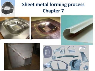
- 2. Introduction • Sheet metal forming operations produce a wide range of consumer and industrial products, such as metal desks, appliances, aircraft fuselages, car bodies, and kitchen utensils. • Sheet-metal forming also called press working, press forming or stamping, is among the most important of metalworking processes, dating back to as early as 5000 B.C., when household utensils, jewelry, and other objects were made by hammering and stamping metals such as gold, silver, and copper. • Compared to those made by casting or forging, sheet metal parts offer the advantages of light weight and shape versatility. Sheet metal forming process Chapter 7
- 3. Introduction • Sheet forming, unlike bulk deformation processes, involves work pieces with a high ratio of surface area to thickness such as cookie sheet hubcaps. • Sheet metal is produced by rolling process. • If the sheet is thin, it is generally coiled after rolling, if thick, it is available as flat sheets or plates, which may have been decoiled and flattened prior to forming them. • In a typical forming operation, a blank of suitable dimensions is first cut from a large sheet, this usually done by a shearing process. Sheet metal forming process Chapter 7
- 4. TABLE 16.1 Process Characteristics Roll forming Long parts with constant complex cross-sections; good surface finish; high production rates; high tooling costs. Stretch forming Large parts with shallow contours; suitable for low-quantity production; high labor costs; tooling and equipment costs depend on part size. Drawing Shallow or deep parts with relatively simple shapes; high production rates; high tooling and equipment costs. Stamping Includes a variety of operations, such as punching, blanking, embossing, bending, flanging, and coining; simple or complex shapes formed at high production rates; tooling and equipment costs can be high, but labor cost is low. Rubber forming Drawing and embossing of simple or complex shapes; sheet surface protected by rubber membranes; flexibility of operation; low tooling costs. Spinning Small or large axisymmetric parts; good surface finish; low tooling costs, but labor costs can be high unless operations are automated. Superplastic forming Complex shapes, fine detail and close tolerances; forming times are long, hence production rates are low; parts not suitable for high-temperature use. Peen forming Shallow contours on large sheets; flexibility of operation; equipment costs can be high; process is also used for straightening parts. Explosive forming Very large sheets with relatively complex shapes, although usually axisymmetric; low tooling costs, but high labor cost; suitable for low-quantity production; long cycle times. Magnetic-pulse forming Shallow forming, bulging, and embossing operations on relatively low-strength sheets; most suitable for tubular shapes; high production rates; requires special tooling. Characteristics of Sheet-Metal Forming Processes
- 5. • Forming of sheet metals is generally carried out by tensile forces, as otherwise the application of external compressive forces could lead to buckling, folding and wrinkling of the sheet. • In some bulk deformation processes, the thickness of the work piece is changed to produce part, whereas in sheet –forming process, any change in thickness is typically due to stretching of the sheet under tensile stresses. • So sever thickness decreases in sheet metal forming should generally be avoided as they can lead to necking and failure, as occurs in a tension test. Sheet Metal - Characteristics and formability
- 6. The mechanics of all sheet forming basically consists of stretching and bending, certain parameters significantly influence the overall operation. These are: 1. Elongation 2. Yield point elongation 3. Anisotropy 4. Grain size 5. Residual stress 6. Springback 7. wrinkling Sheet Metal - Characteristics and formability
- 7. Elongation : • When a specimen is subjected to tension it is first undergoes uniform elongation up to the UTS, after which it begins to neck. This elongation is then followed by further nonuniform elongation until the specimen fractures. • Because the sheet will be stretched during forming process, high uniform elongation is thus desirable for good formability, Characteristics of Sheet-Metal Forming Processes
- 8. Elongation : • For a material that has a true-stress-true-strain curve represented by the equation: • The strain at which necking begins is given by ϵ = n. • Thus, the true uniform strain in a simple stretching operation is numerically equal to the strain-hardening exponent, n. • A high value of n indicates large uniform elongation and thus is desirable for sheet forming. Characteristics of Sheet-Metal Forming Processes
- 9. Yield point elongation Low carbon steels exhibit a behavior which is called yield point elongation, involving upper and lower yield points. This yield point elongation is usually on the order of a few percent. In yield point elongation, a material yields at a given location; subsequent yielding occurs in adjacent areas where the lower yield point is unchanged. When the overall elongation reaches the yield point elongation, the entire specimen will undergo a uniform deformation Characteristics of Sheet-Metal Forming Processes
- 10. Yield point elongation • This behavior of low carbon steel produces Lueder’s band (Also called stretcher strain marks or worms) on the sheet. • These bands consist of elongated depressions on the surface of the sheet and can be objectionable in the final product because of its uneven surface appearance. • These bands also can cause difficulties in subsequent coating and painting operation. Characteristics of Sheet-Metal Forming Processes
- 11. Yield point elongation • Stretcher strain marks can be observed on the curved bottom of the steel cans for common household products. • Aluminum cans don’t exhibit this behavior because aluminum alloys do not demonstrate yield point elongation. Characteristics of Sheet-Metal Forming Processes
- 12. Yield point elongation • The magnitude of the yield point elongation depends on: 1. The strain rate (with higher rates, the elongation generally increase). 2. The grain size of the sheet metal (as the grain size decreases, the yield point elongation increases. Characteristics of Sheet-Metal Forming Processes
- 13. Yield point elongation • The usual method of a voiding these marks is to eliminate or to reduce yield-point elongation by reducing the thickness of the sheet 0.5 to 1.5% by cold rolling , a process known as temper rolling or skin rolling (preferred grain orientation , or directionality, of sheet metal). • Because of the strain aging. The yield-point elongation reappears after a few days at room temperature. Thus, the sheet metal should be formed within a certain period of time (such as from one to three weeks for rimmed steel) to avoid the reappearance of stretcher strain. Characteristics of Sheet-Metal Forming Processes
- 14. Temper rolling Skin rolling Characteristics of Sheet-Metal Forming Processes
- 15. Anisotropy Another important factor influencing sheet-metal forming is anisotropy (preferred grain orientation) , or directionality, of sheet metal. Anisotropy is acquired during the thermo mechanical processing history of the sheet. There are two types of anisotropy: 1. Crystallographic anisotropy (preferred grain orientation) 2. Mechanical fibering ( alignment of impurities, inclusions and voids. These behaviors are particularly important in deep drawing of sheet metals. Characteristics of Sheet-Metal Forming Processes
- 16. Grain size Grain size of the sheet metal is important for two reasons: 1. Because of its effect on mechanical properties of the material (larger size grain is different from smaller size grain) how??? [smaller grain size exhibit more formability than larger grain size] 2. Because of its effect on surface appearance of the formed part The coarser the grain, the rougher the surface appears (orange peel) An ASTM grain size of No. 7 is typically preferred for general sheet-metal forming Characteristics of Sheet-Metal Forming Processes
- 17. Residual stresses Residual stresses can develop in sheet-metal parts because of the nonuniform deformation that the sheet undergoes during forming . (Residual stresses are stresses that remain within a part after it has been deformed plastically non uniformly and all external forces have been removed). Disturbing the equilibrium of residual stresses, such as by bending or stretching of it, the part may distort. We should remove residual stresses prior to forming. Characteristics of Sheet-Metal Forming Processes
- 18. Springback • Because they are generally thin and are subjected to relatively small strain during forming, sheet-metal parts are likely to experience considerable springback • Because all materials have a finite modulus of elasticity, plastic deformation is always followed by elastic recovery upon removal of the load. In bending, this recovery is known as springback. • This effect is particularly significant in bending and other forming operations where the bend radius-to-sheet- thickness ratio is high, such as in automotive body parts. Characteristics of Sheet-Metal Forming Processes
- 19. Wrinkling In the sheet metal forming the metal is typically subjected to tensile stresses, the method of forming may be that compressive stresses are developed in the plane of the sheet. An example in sheet metal forming is the wrinkling of the flange in deep drawing because of the circumferential compressive stresses that develop in the flange. Other terms used to describe this phenomena are folding and collapsing. Characteristics of Sheet-Metal Forming Processes
- 20. Wrinkling • The tendency for wrinkling in sheet metals increases with: 1. Decreasing thickness 2. Nonuniformty of the thickness of the sheet 3. Increasing length or surface area of the sheet that is not constrained or supported. 4. Lubricants that are trapped or are not distributed evenly at the die-sheet metal interfaces can also contribute to the initiation of wrinkling Characteristics of Sheet-Metal Forming Processes
- 21. Coating sheet • Sheet metals, especially steel, are precoated with a variety of the organic coating, films and laminate. • Coatings are used primarily for appearance as well as for corrosion resistance. • Coatings are applied at thicknesses generally range from 0.0025 to 0.2mm. • Coatings are available with wide range of properties, such as flexibility, durability, color, and gloss, resistance to abrasion and chemicals. • Zinc is used extensively as a coating on sheet steel (galvanized steel by hot dipping) to protect it from corrosion, particularly in the automotive industry Characteristics of Sheet-Metal Forming Processes
- 22. • High strength • Good dimensional accuracy • Good surface finish • Relatively low cost Advantages of Sheet Metal Parts Sheet Metal Processes 1. Cutting – Shearing to separate large sheets; or cut part perimeters or make holes in sheets 2. Bending – Straining sheet around a straight axis 3. Drawing – Forming of sheet into convex or concave shapes
- 23. Cutting Operations Shearing side view front view Typically used to cut large sheets into smaller sections for subsequent operations
- 24. shearing • The shearing process involves cutting sheet metal, as well as plates, bars, and tubing of various cross section, into individual pieces by subjecting it to shear stress, typically using a punch and a die, similar to action of paper punch. • The punch and die may be of any shape, such as circular or straight blades, similar to a pair of scissors. • Important variables in the shearing process are: 1. The punch force. 2. The speed of the punch 3. The edge condition of the sheet. 4. The punch and die materials. 5. The punch-die clearance. 6. Lubrication.
- 25. Shearing (Cutting) punch begins to push into work, causing plastic deformation punch penetrates into work causing a smooth cut surface fracture is initiated at both cutting edges just before the punch contacts work C, is the clearance
- 26. The overall features of a typical sheared edge for the two sheared surfaces are illustrated Shearing (Cutting) Note that the edges are neither smooth nor perpendicular to the plane of sheet.
- 27. The clearance, c, is the major parameter that determine the shape and quality of the shear edges Shearing (Cutting)
- 28. • As the clearance increases, the sheared edges become rougher and the deformation zone becomes larger. The material is pulled into clearance area into the die rather than be sheared, and the sheared edges become more and more round. In fact, if the clearance is too large, the sheet metal is bent and thus subjected to tensile stresses Effect of the clearance, c, between punch and die on the deformation zone in shearing. As the clearance increases, the material tends to be pulled into the die rather than be sheared Shearing process
- 29. As clearance decreases, the deformation zone is subjected to high shear strain. The width of this zone depends on the rate of shearing, that is, the punch speed. With increasing punch speed, the heat generated by plastic deformation is confined to smaller zone, and consequently the sheared surface is smoother Shearing process
- 30. In practices, clearances usually range between 2 and 8% of the sheet thickness. In general, clearances are smaller for softer materials, and they are higher as the sheet thickness increases. As indicated in the figure below, the sheared edges can undergo sever cold working, which, in turn, can adversely affect the formability of the sheet during subsequent operation. Shearing process
- 31. • Observation of the shearing mechanism reveals that shearing usually starts with the formation of cracks on both the top and bottom edges of the sheet (at A and B). These crack eventually meet, resulting in complete separation and a rough fracture surface Shearing process
- 32. The smooth, shiny, and burnished surfaces are from the contact and rubbing of the sheared edges against the punch and the die as shown. 1. The burnished surface is in the lower region, because this region is the section that rubs against the die wall. 2. The burnished surfaces (on the sheet it self ) is on the upper region and results from rubbing against the punch. The ratio of the burnished-to-rough areas on the sheared edge increases with increasing ductility of the sheet metal and decreasing with increasing sheet thickness and clearance. Shearing process rough and smooth, shiny edges
- 33. Note also the formation of burr. Burr height increases with: 1. Increasing clearance 2. Increasing ductility 3. Tooling with dull edges is also a major factor in burr formation. Shearing process
- 34. Small clearance – ……………… – …………………. – ……………………. Large clearance – ……………………… – …………………….. – ……………………… As clearance increases, the material tends to be pulled into the die rather than be sheared. More punch and die wear Higher cutting force Better edges Rougher edges Larger deformation zone Larger burrs Clearance: The clearance determines the shape and quality of the sheared edge, so the control of the clearance is important! Burr: Burr length increases with clearance & ductility of metal. Tools with dull edges create burrs. Shearing process
- 35. Clearance in Sheet Metal Cutting • Recommended clearance can be calculated by: c = at where c = clearance; a = clearance allowance; and t = stock thickness. • Allowance a is determined according to type of metal. Clearance Allowance for Three Metal Groups a 1100S and 5052S aluminum alloys, all tempers 0.045 2024ST and 6061ST aluminum alloys; brass, soft cold rolled steel, soft stainless steel 0.060 Cold rolled steel, half hard; stainless steel, half hard and full hard 0.075 Low “c” for soft materials High “c” for hard materials
- 36. Punch force • An approximate empirical formula for estimating the maximum punch force, is given buy: • UTS: is the ultimate tensile strength of sheet metal. • t : is the thickness. • L : is the total length of the sheared edge. For round hole of diameter D, L=πD tLUTSF )(7.0max F=S*t*L Where: S= Shear strength t= Sheet thickness L= Length of cutting edge If shear strength is not known, cutting force can be estimated as:
- 37. Example • Estimate the force required in punching a 25 mm diameter hole through a 1.8 mm thick 5052 –O aluminum sheet at room temperature. UTS is 190 Mpa. • Solution : Force = 1.8793 * 10^6 N
- 38. Various operations that are based on the shearing process. First it should be noted that in punching, the slug is discarded (the sheared slug is scrap, or may be used for some other purpose). In blanking, the slug is the part it self, and the rest is scrap. Shearing operations Slug
- 39. 1. die cutting • Die cutting typically consists of various operations where the parts produced have various uses, particularly in their assembly with other components of a product Shearing operations • The following processes are common shearing operation
- 40. 1. Die cutting a) Perforating : that is punching a number of holes in the sheet metal b) Parting : shearing the sheet into two or more pieces, usually when the adjacent blanks do not have a matching contour c) Notching : removing pieces or various shape from the edges. d) Slitting and lancing : leaving a tab on the sheet without removing any material Shearing operations
- 41. Lancing
- 42. 2. fine blanking Very smooth and square edges can be produced by fine blanking. The basic die design involves a V-shaped stringer that locks the sheet tightly in place and prevents the type of distortion of the material (Prevents distortion at sheared edges). Fine blanking involves clearances on the order of 1% of the sheet thickness, as compared with as much as 8% in ordinary shearing operations. Very tight (<1%) clearances), Therefore tight tolerances .possible• Therefore tight tolerances possible Shearing operations
- 43. 2. fine blanking The thickness of the sheet may typically range from 0.5 to 13 mm A suitable sheet hardness is typically in the range of 50-90 HRB Shearing operations
- 44. 3. slitting • Slitting is a shearing operation carried out with a pair of circular blades, similar to those on a can opener. The blades follow either a straight line or curved path. • There are two types of slitting equipment: a) In the driven type, the blades are powered b) In the pull-through type, the strip is pulled through idling blades Shearing operations
- 45. Slitting operations Straight slitting is commonly used in cutting wide sheet, as delivered by rolling mill, into narrower strips for further processing into individual parts.
- 46. 4. Nibbling • In this operation, a machine called a nibbler moves a straight punch up and down rapidly into a die. The sheet is fed through the punch- die gap, making a number of overlapping holes. • An intricate notches can thus produced using standard punches. • The process is economical for small production runs since no especial dies are required. Shearing operations
- 47. Scrap in shearing • The a mount of scrap produced in shearing operation can be significantly, being as high as 30% of the original sheet for large pieces. • It is an important factor in manufacturing costs • Scrap can be reduced significantly by proper arrangement of shapes on the sheet to be cut, called layout and nesting. • Computer-aided design techniques are now available for minimizing scrap.
- 48. Because the formability of a sheared part can be directly influenced by the quality of its sheared edges, clearance control is important. In practice, clearances usually ranged between 2 and 8%. Generally the thicker the sheet, the larger is the clearance, to as much as 10%, however, the smaller the clearance, the better is the quality of the sheared edge. In a process called shaving, the extra material from a rough sheared edge is trimmed by cutting Shearing dies
- 49. Schematic illustration of shaving on a sheared edge. (a) Shaving a sheared edge. (b) Shearing and shaving combined in one punch stroke. Shearing dies
- 50. Punch and dies shape The area being sheared at any instant can be controlled by beveling the punch and die surfaces The beveled geometry is particularly suitable for shearing thick sheets because 1. it reduces the total shearing forces and also 2. reduces the noise level during punching
- 51. Some parts requiring multiple operations such as punching and blanking are made at high production rates using progressive dies. In which the coil strip is fed through the dies, and a different operation is performed at the same station with each stroke of a series of punches Progressive dies
- 52. Miscellaneous methods of cutting sheet metal 1. The sheet or plate may be cut with a band saw uses a blade consisting of a continuous band of metal with teeth along one edge to cut various workpieces. 2. Oxyfuel-gas (flame) cutting : may be employed particularly for thick plates, as widely used in shipping and heavy-construction industries (it can cut thicknesses from 0.5mm to 2,500mm). 3. Friction sawing : involves the use of blade, that rubs against the sheet or plate at high surface speed. ( a type of band sawing that uses high speed to generate heat to soften the metal in front of the blade) 4. Water-jet cutting : are effective operations on sheet metals as well as on nonmetallic materials 5. Laser beam cutting : is now widely used, with computer controlled equipment, for high productivity, cons
- 53. Oxyfuel-gas (flame) cutting • A mixture of oxygen and the fuel gas is used to preheat the metal to its 'ignition' temperature which, for steel, is 700°C - 900°C (bright red heat) but well below its melting point. • A jet of pure oxygen is then directed into the preheated area instigating a vigorous exothermic chemical reaction between the oxygen and the metal to form iron oxide or slag. • The oxygen jet blows away the slag enabling the jet to pierce through the material and continue to cut through the material.
- 54. Friction sawing Friction sawing :a type of band sawing that uses high speed to generate heat to soften the metal in front of the blade)
- 55. Water-jet cutting • Water jet cutting: is an industrial tool capable of cutting a wide variety of materials using a very high- pressure jet of water, or a mixture of water and an abrasive substance. The term abrasivejet refers specifically to the use of a mixture of water and abrasive to cut hard materials such as metal or granite, while the terms pure waterjet and water-only cutting refer to waterjet cutting without the use of added abrasives, often used for softer materials such as wood or rubber. • It is the preferred method when the materials being cut are sensitive to the high temperatures generated by other methods. • Most high-pressure pumps at this time, though, operated around 500–800 psi (3–6 MPa), some reaching 1600 psi (11 MPa).
- 56. Laser beam cutting • The laser beam is focused for cutting. All its power is bundled onto one point, usually with a diameter of less that half a millimeter. Where the focused beam strikes the workpiece, the metal immediately begins to melt. It even partly burns or evaporates. • The highly focused, high-density energy melts and evaporates small portions of the workpiece in a controlled manner. Laser converts electrical energy into a highly coherent light beam with the property of : Monochromatic (single wave length) This property allow laser light to be focused, using optical lenses, onto a very small spot with resulting high power densities. Reflectivity and thermal conductivity of the workpiece are important factors in LBC. The lower these quantities, the more efficient is the process
- 57. In sheet metal forming operations, the blank is typically supplied in one piece, usually cut from a large sheet, and has a uniform thickness. An important technology in sheet-metal forming, particularly in the automotive industry, involves laser butt welding of two or more pieces of sheet of different thicknesses and shapes (Tailor -welded blanks, or TWB). The welded sheet is subsequently formed into a final shape buy using any of the processes of sheet metal forming. Tailor – welded blanks: Laser Welding
- 58. • Advantages: 1. Productivity is increased. 2. The need for subsequent spot welding of the product is reduced or eliminated 3. Scrap is reduced 4. Dimensional control is improved • It should be noted, that because the sheet thicknesses involved are small, proper alignment of the sheet prior to welding is essential Tailor – welded blanks: Laser Welding
- 59. • One of the most common metal working is bending, a process that is used not only to form parts such as flanges, and corrugations, but also to impart stiffness (by increasing the moment of inertia). Example a flat strip of metal is much less rigid than one is formed into a V cross section Bending of sheet and plate
- 60. Straining sheet metal around a straight axis to take a permanent bend. Bending Bending of sheet metal Metal on inside of neutral plane is compressed, while metal on outside of neutral plane is stretched. A + A’ = 180˚
- 61. • Bend allowance : is the length of the neutral axis in the bend area and is used to determine the blank length for a bent part. It depends on 1. Bend radius 2. Bend angle • an approximate formula for the bend allowance. Lb, is given α is the bend angle in radians, R is the bend radius, k is a constant, values usually range from 0.33 for R<2t to 0.5 for R>2t t is the sheet thickness. Bending of sheet and plate )( ktRLb
- 62. The outer fibers of a part being bent are subjected tension, and the inner fibers to compression Theoretically, Engineering Strains at the outer and inner fibers are equal in magnitude and they are: Due to shifting of the neutral axis toward the inner surfaces, the length of bend L, is smaller in the outer region than in the inner region ( bending a rectangular eraser). Consequently, the outer and inner strains are different, with the differences increasing with decreasing R/t ratio. (decreasing bend radius) Minimum bend radius 1)/2( 1 tR ee io
- 63. • As the ratio R/t decreases, the tensile strain at the outer fiber increases, and the material may crack after a certain strain is reached. • The bend radius, R, at which crack appears on the outer surface of the bend is called the minimum bend radius. • The minimum bend radius to which a part can be bent safely is normally expressed in terms of its thickness, such as 2t, 3t, 4t. • For example, a bend radius of 3t indicates that the smallest radius to which the sheet can be bent without cracking is three times its thickness 1)/2( 1 tR ee io Minimum bend radius
- 64. The minimum bend radii for various materials have been determined experimentally; some typical results are give in the table below Minimum Bend Radius for Various Materials at Room Temperature
- 65. Studies have been conducted to establish a relationship between the minimum R/t ratio and a particular mechanical property of the material. Based on the assumption that : The true strain at cracking on the outer fiber in bending is equal to the true strain at fracture, εf , of the material in a simple tension test. ) 100 100 ln()ln( rA A f o f Where r is the percent reduction of area of the sheet in a tension test. ) )2/( ln() 1)/2( 1 1ln()1ln( tR tR tR eoo T the true strain at fracture, εf , of the material in a simple tension test. Minimum bend radius The true strain at cracking on the outer fiber in bending By equating the above expressions Minimum R/t= (50/r) -1
- 66. Minimum Bend Radius and Ductility • There is a relationship between R/t and ductility, expressed as the tensile reduction in area, r • Not that as R/t ratio approaches zero (complete bendability; that is the material can be folded over itself, like apiece of paper) at a tensile reduction of area of 50 • The lower the ductility (smaller reduction in area) the larger the R/t [large bend of radius] Minimum R/t= (50/r) -1
- 67. Factor affecting bendability Bendability depends on the edge condition of the sheet being bent. 1. Rough edges, because rough edges have various locations of stress concentration. Bendability decreases as edges roughness increases. Removal of the rough edges by shaving, or machining, greatly improves the resistance to edge cracking during bending 2. The amount of cold working the edges undergo during shearing is another important factor. Removal of the cold worked regions such as by annealing, greatly improves the resistance to edge cracking during bending.
- 68. 3. Another important factor in edge cracking is the amount and shape of inclusions in the sheet metal. Inclusions in the form of stringers are more detrimental than globular- shaped inclusions; consequently, anisotropy of the sheet is also important in bendability, cold rolling of the sheets results in anisotropy because of the alignment of the impurities, inclusions, and voids (mechanical fibering). Factor affecting bendability
- 69. Stringers inclusions globular-shaped inclusions. Factor affecting bendability
- 70. Forming by Bending • Advantages – Easy to perform – Simple, low cost tooling – Fairly precise • Disadvantages – Limited in the shapes it can produce – Spring back difficult to estimate – Some material difficult to bend without tearing or necking
- 71. • Because all materials have a finite modulus of elasticity, plastic deformation is always followed by elastic recovery upon removal of the load. In bending, this recovery is known as springback. Springback
- 72. Springback a) The final bend radius is larger than radius to which it is bent. b) The final bend angle after springback is smaller than the angle to which it is bent • This phenomena can easily be observed and verified by bending a piece of wire or short strip metal. • This phenomena can easily be observed and verified by bending a piece of wire. • Note that springback will not occur only in bending flat sheets or plate, but also in bending bars and rods
- 73. Where Ri and Rf are the initial and final bend radii Springback A quantity characterizing springback is the springback factor , Ks: Because the bend allowance is the same before and after bending, the bend allowance is as follow for pure bending: ffii t R t R ) 2 () 2 ( Bend allowance = From this relation Ks is defined as : 1)/2( 1)/2( tR tR K f i i f s From the above expression that Ks depend on the ratio R/t The condition of Ks =1 indicates that there is no springback, and ks =0 indicates that there is a complete elastic recovery. For the case that k=0.5
- 74. The amount of elastic recovery depends on the stress level and the modulus of elasticity, E, of the material. Thus, elastic recovery increases with the stress level and with decreasing elastic modulus based on this observation an approximate formula has been developed to estimate springback as: Springback 1)(3)(4 3 Et YR Et YR R R ii f i Y is the yield stress of the material.
- 75. 1. Overbending : can be achieved by rotary bending technique in which the upper die has a cylindrical rockers and is free to rotate. Compensation for Springback
- 76. 2. Coining : is a accomplished by subjecting a high localized compressive stresses between the tip of the punch and the die surface. Compensation for Springback
- 77. 3. Because springback decreases as yield stress decreases. Bending at elevated temperatures will decrease the yield stress of the material. Decreasing the yield stress of the material decreases the springback. (recall the effect of elevated temperature on the yield point) Compensation for Springback
- 78. 4. Stretch bending : in which the part is subjected to tension while being bent, consequently decreasing springback Compensation for Springback
- 79. Bending force can be estimated by assuming that the process is that of the simple bending of a rectangular beam. Thus bending force is a function of the material’s strength, length and thickness of the part (L and t). Excluding friction, the general expression for the maximum bending force, Fmax, is Force in bending Where the factor k include various factors, including friction: K values for V-dies ( 1.2 - 1.33 ), for wiping dies ( 0.3 - 0.34 ) UTS: the ultimate tensile stress of the material. W: part width in direction of bend axis L: length of the part. t: thickness of the part
- 80. Common bending operations 1.Press-brake forming : sheet metal or plate can be bent with simple fixtures, using a press. • Parts that are long (7m or more) and relatively narrow are usually bent in a press brake. • This machine uses long dies in a mechanical or hydraulic press is suitable for small production runs
- 81. 2. beading : in this operation, the edge of the sheet is bent into cavity of a die. Beading improves 1. The appearance of the part and 2. Eliminates exposed sharp edges, which may be a safety hazard. 3. Also the bead impart stiffness to the part by virtue of the higher moment of inertia of the edges Common bending operations a) Bead forming with a single die. (b)-(d) Bead forming with two dies in a press brake.
- 82. 3. Flanging : is a process of bending the edges of the sheet metals, typically to 90o, for the purpose of : 1. imparting stiffness, 2. appearance, 3. or for assembly with other component Common bending operations
- 83. 4. Hemming. • In the hemming process (also called flattening), the edge of the sheet is folded over itself • Advantages: 1. Hemming increase the stiffness of the part 2. Improves its appearance 3. Eliminate sharp edges Common bending operations 5. Seaming. • Involves joining two edges of sheet metal pieces by hemming
- 84. Tube bending • The oldest and simplest method of bending a tube or a pipe is to pack the inside with loose particles (typically sand) and bend it in a suitable fixture. • The packing prevents the tube from buckling inward. • Tubes also can be bulged with various flexible internal mandrels.
- 85. Stretch Forming Sheet metal is stretched and simultaneously bent to achieve shape change (1) start of process (2) die is pressed into the work with force Fdie, causing it to be stretched and bent. F = stretching force The shape is produced entirely by tensile stretching so the limiting strain is that at necking. Sheet is gripped by two jaws at its edges. Form block is slowly raised by the ram to deform sheet above its yield point. The sheet is strained plastically to the required final shape Controlling the mount of stretching is important to avoid tearing.
- 86. Stretch forming • Forming by using tensile forces to stretch the material over a tool or form block. • In this operation, the sheet metal is clamped around its edges and stretched over a die. • In most stretch-forming operations, the blank is clamped along its narrower edges and stretched longwise. Loading Pre-Stretching Wrapping Release Miscellaneous forming process
- 87. • Used most extensively in the aircraft industry to produce parts of large radius of curvature. (normally for uniform cross section). Also for automobile door panels. • Required materials with appreciable ductility, Aluminum skins for Boeing 767 and 757 fuselages, for example, are made by stretch forming. Stretch forming Miscellaneous forming process
- 88. Stretch Forming: equipment Stretch Forming with Reconfigurable Tool
- 90. Stretch forming
- 91. Force Required in Stretch Forming fLtYF where F = stretching force L = length of sheet in direction perpendicular to stretching t = instantaneous stock thickness Yf = flow stress of work metal Calculate the force required to stretch form a wing span from a sheet of 2219 aluminum having a cross-sectional area of 13x305 mm, a strength coefficient strength of 250 MPa and strain hardening exponent 0.3. Example
- 92. Bulging The basic process of bulging involves placing a tubular part in a split female die and expanding it with the rubber or polyurethane plug. The punch is the retracted, the plug returns to its original shape, and the part is removed by opening the split die. Typical product made by this process includes: bellows,coffee and water pitchers. Polyurethane plugs are very resistant to abrasive, sharp edges and wear Bulged tube Miscellaneous forming process
- 93. Manufacturing of Bellows Bulging Miscellaneous forming process
- 94. This process consists of forming a number of shallow shapes (numbers, letters) or designs on sheet metal. The part may be embossed with male and female dies The female die is replaced with a rubber pad. The pressure is applied is typically on the order of 10 Mpa The outer surface of the sheet is protected from damage or scratches because it is not in contact with hard metal surface during forming Embossing Figure 16.38 Examples of the bending and the embossing of sheet metal with a metal punch and with a flexible pad serving as the female die. Source: Miscellaneous forming process
- 95. In this process, one of the dies in a die set is made of flexible material such as rubber membrane or polyurethane In hydroforming, or fluid forming process, the pressure applied over a flexible membrane with a maximum pressure reaching 100 Mpa. Deeper draws are obtained than in conventional deep drawing, the reason being that the pressure around the rubber membrane forces the part being formed against the punch Hydroforming (fluid forming process) Miscellaneous forming process
- 96. Advantages: 1. The capability to form complex shapes. 2. Flexibility and ease of operation. 3. The avoidance of damage to the surfaces of the sheet. 4. Low die wear. 5. Low tooling cost. Hydroforming (fluid forming process)
- 97. Spinning involves the forming of axisymmetric parts over a rotating mandrel, using rigid tools or rollers. The equipment used is similar to lath with various special features Three types of spinning: 1. Conventional spinning 2. Shear spinning 3. Tube spinning spinning Miscellaneous forming process
- 98. • Spinnability: the maximum reduction in thickness of the material to which a part can be subjected by spinning without fracture. Spinning
- 99. Conventional spinning In conventional spinning, a circular blank of a flat sheet metal is held against a rotating mandrel while a rigid tool deforms and shapes it over the mandrel. The tool may be actuated either manually or by a hydraulic mechanism. The operation involves a sequences of passes and requires considerable skill. The process is suitable for conical and curvilinear shapes, which would otherwise be difficult to form by other methods. Most spinning is performed at room temperature For thick parts or metals with low ductility or high strength require spinning at elevated temperature. Part diameter may range up to 6 m in diameter
- 101. In shear spinning, also called power spinning or flow turning, an axisymmetric conical or curvilinear shape is generated in a manner whereby the diameter of the parts remains constant. Parts typically made by this process include rocket-motor casings and missile nose cones. The operation is completed in a relatively short time If the operation is carried out at room temperature, the spun part has relatively a higher yield strength than original material, but lower ductility. Parts typically up to about 3 m in diameter can be spun to close dimensional tolerances. Shear spinning
- 102. Shear spinning
- 103. Tube spinning In tube spinning, tubes or pipes are reduced in thickness by spinning them on cylindrical mandrels, using rollers. The operation may be carried out externally or internally. The reduction in wall thickness results in a longer tube, because of volume constancy. Thickness is reduced
- 104. HERF describes sheet-metal forming process that use chemical, electrical, or magnetic sources of energy. They are called high-energy-rate processes because of the high amount of energy is released in a very short time. High-Energy-Rate Forming (HERF) Miscellaneous forming process Processes to form metals using large amounts of energy over a very short time.
- 105. (1) Explosive Forming Use of explosive charge to form sheet (or plate) metal into a die cavity Explosive charge causes a shock wave whose energy is transmitted to force part into cavity. Applications: large parts, typical of aerospace industry. High-Energy-Rate Forming (HERF setup explosive is detonated shock wave forms part
- 106. The rapid conversion of the explosive into gas generates a shock wave. The pressure of this wave is sufficiently high to force the metal into die cavity (1) Explosive Forming High-Energy-Rate Forming (HERF) 1. In this process, the sheet is clamped over a die 2. The air in the die is evacuated 3. Then the whole assembly is lowered into a tank filled with water 4. An explosive charge is the placed at a certain distance from the sheet surface, and detonated setup explosive is detonated shock wave forms part
- 107. Detonation speeds are typically 6700m/s, and the speed at which the sheet metal is formed is to be estimated on the order of 30 to 200m/s. Safety is an important aspect in explosive forming. Suitable for low-quantity production runs of lager parts (steel plates 25 mm thick and 3.6 m in diameter have been formed by this method) (1) Explosive Forming High-Energy-Rate Forming (HERF)
- 108. Electro Hydraulic Forming “Electric Discharge forming” Electrical energy is accumulated in large capacitors and then released to the electrodes. The source of energy in this process is the spark from two electrodes. The rapid discharge of this energy through the electrodes generates a shock wave; which is strong enough to form the part. This process is Similar to explosive forming except: 1. That it utilizes a lower level of energy, therefore, its safer. 2. And is used for smaller workpiece (2) Electro Hydraulic Forming: High-Energy-Rate Forming (HERF)
- 109. The energy stored in a capacitor bank is discharged rapidly through a magnetic coil, produces two magnetic fields, which in turn produces forces. The forces produced by the two magnetic fields oppose each other; thus there is a repelling force between the coil and the tube. These high forces generated collapse the tube over the inner side of the die - Presently the most widely used HERF process. - Applications: tubular parts (i.e. swaging) High-Energy-Rate Forming (HERF) (3) Electromagnetic Forming: Electromagnetic Forming “Magnetic Pulse forming”
- 110. Miscellaneous forming process Superplasticity Superplasticity: Conventional metals elongate 10 to 30%. Ultra-fine grained materials reach 100-3000%. Used to form complex parts at high temperature. Large deformations possible, something that would normally fracture parts, but large deformation + low strain rate = long time to perform deformation.
- 111. The superplastic behavior of some very fine grained alloys ( 10-15µm), where very large elongations (up to 2000%) are obtained at certain temperatures and low strain rates Miscellaneous forming process Superplasticity Superplastic deformation of an Al alloy These alloys are : Zinc alloys, Titanium alloys (Ti-Al-V alloys), Aluminum alloys (Al- Zn-Mg and Al-Cu), Inconel 718 (Ni-Cr alloy), and stainless steels (Fe-Cr-Ni alloy ) can be made superplastic. These alloys can be formed into complex shapes by employing traditional metal working or polymer- processing techniques Superplasticity is the ability of a material to withstand very large amounts of uniform elongation without the occurrence of necking prior to fracture.
- 112. Superplasticity Important elements in superplastic properties to attain such deformation: 1. Low strain rate (~3*10-4/s) (so it is not practical). 2. High temperature (above 0.4Tm). 3. Small grain size (less than 20μm for metallic alloys). In the past, Superplastic forming was available at relatively low strain rates, typically about 1% per min. At this strain rate, about 1 hr is needed to form an advanced structural component; too long to be economically effective. Superplasticity at higher strain rates, however, can be expected to stimulate broad commercial interest in superplastic forming. Example: a strain rate higher than 100% per minute is considered economically practical. Such a strain rate would allow the forming of relatively complex structures in less than three minutes, including set-up time. where C = strength constant m = strain-rate sensitivity exponent (0.3-0.85 for superplastic materials). m C
- 113. Superplastic Forming Process The SPF process uses superplastic materials to form very complex sheet metal parts. Dies are heated in a press (900°C for titanium alloys) and inert gas pressure is applied at a controlled rate. SPF can produce parts that are impossible to form using conventional methods.
- 114. Superplastic Forming Process Benefits... The high ductility and relatively low strength of superplastic alloys present the following advantages: 1. Lower Tooling cost: because of low strength of the material at forming temperatures, and hence lower strength of tooling 2. Producing complex shape : the ability to form complex shape in one piece, with fine detail, close dimensional tolerance, and eliminating secondary operation. 3. Material saving ; because of the good formability of superplastic materials, thus, no waste in the material. 4. Little or no residual stresses in the formed parts
- 115. A superplastically formed Al-Li alloy component Elimination of unnecessary joints, fasteners, welding or adhesives. Reduction of subsequent machining. Minimization of materials waste. An integrated aluminum structure, for example, traditionally manufactured by welding four pieces of metal, can be manufactured in a single operation through superplastic forming. Superplastic Forming Process Courtesy of www.accudyneeng.com An Al-alloy component
- 116. Superplastic Forming with Diffusion Bonding An important aspect of superplastic forming is the ability to fabricate sheet-metal structures by combining diffusion bonding. SPF/DB parts are produced by joining several sheets in a specific pattern and then superplastically expanding the sheets to produce an integrally-stiffened structure [Typical structures in which flat sheets are diffusion bonded and then formed into desired structures] These structures are relatively thin and high stiffness-to-weight ratios; consequently, they are particularly important in aerospace applications . Courtesy of www.spfintl.com A Ti-alloy aircraft
- 117. Superplastic Forming with Diffusion Bonding
- 118. Deep drawing first developed in 1700s, is an important sheet- metal forming process. Typical parts produced by this method include beverage cans, pots and pans, containers of all shapes and sizes, and automobile body panels. The process, is generally called deep drawing (meaning forms deep part), the basic operation also produces parts with moderate depths. Deep drawing
- 119. The basic parameters in deep drawing a cylindrical cup are: A circular sheet blank with a diameter Do and thickness to is placed over a die opening with a corner radius Rd. the blank is held in the place with blankholder under a certain force. A punch with a diameter Dp and a corner radius Rp moves downward and pushes the blank into die cavity, thus forming a cup. Deep drawing
- 120. Steps in Deep Drawing: 1) Initial contact 2) Bending 3) Straightening 4) Friction and compression 5) Final shape Deep Drawing
- 121. • The significant variables in deep drawing: 1. Properties of the sheet metal 2. Ratio of the blank diameter to the punch diameter 3. Sheet thickness 4. Clearance between the punch and the die 5. Corner radii of the punch and die 6. Friction at the punch, die, and workpiece interfaces 7. Blankholder force 8. Speed of the punch Deep drawing
- 122. Cup Bottom: - Near Zero Strain - No Friction Cup Flange: - Compression and - Friction Zone Cup Wall: - Fracture Zone* - No Friction Die Radius: - Bending and - Friction Zone Punch Radius: - Bending and - Friction Zone Deep Drawing - Variables *Failure may result from thinning of the cup wall. Deformation of an element in the flange Deformation of an element in the wall
- 123. Deep Drawing - Variables and Defects Die radius too small Punch radius too small During drawing, when the blank moves into the die, compressive circumferential stresses are induced in the flange. – This causes flange to wrinkle. - Using beads to control contraction in the flange and the movement of the material into die cavity – Eg: try forcing a circular sheet of paper into a drinking glass. Effect of die and punch radii on deep drawing:
- 124. At an intermediate stage during the deep drawing operation, the work piece is subjected to state of stress indicated in the figure below • On element A (flange) in the blank, the radial tensile stresses is due to the blank being pulled into the cavity. • The compressive stresses is due to the pressure applied by the blank holder. Deep Drawing - Mechanism -Variables
- 125. With a free body diagram of the blank along its diameter, it can be shown that the radial tensile stresses lead to compressive hoop stresses on element A (flange). Under this state of stress, element A (flange) contracts in the compressive hoop stress and elongates in the radial direction. It should be noted that it is the compressive hoop stresses in the flange that tend to cause the flange to wrinkle during drawing, thus it is necessary to provide a suitable balnkholder force Deep Drawing - Mechanism -Variables
- 126. The punch transmits the drawing force, F, through the walls of the cup and to the flange that is being drawing into die cavity. The cup wall, which is already formed, is subjected principally to longitudinal tensile stresses as shown in the figure. The tensile hoop stress on the element shown in the figure is caused by the cup being held tightly on the punch because of its contraction under the longitudinal tensile stresses in the cup wall (cup of coffee and plastic bag) Deep Drawing - Variables and Defects And because the cup is constrained by the rigid punch, the element shown in the figure dose not undergo any width change, but elongates in the longitudinal direction.
- 127. If the thickness of the sheet as it enters the die cavity is more than the clearance between the punch and die, it has to be reduced by a deformation called ironing. By controlling the clearance, C, ironing produce a cup with a constant wall thickness. Because of the volume constancy, an ironed cup will be longer than a cup produced with a large clearance. Thus, ironing can correct earing that occurs in deep drawing. Ironing Ironing to achieve a more uniform wall thickness in a drawn cylindrical cup.
- 128. Shapes other than Cylindrical Cups • Square or rectangular boxes (as in sinks) • Stepped cups • Cones • Cups with spherical rather than flat bases • Irregular curved forms (as in automobile body panels) Each of these shapes presents its own unique technical problems in drawing Very important commercial process.
- 129. Methods to reduce diameter of drawn cups: • Redrawing: For parts with high DR, they require more than one drawing. • Reverse Redrawing: Metal is bent in opposite direction. Reverse Redrawing Redrawing Methods for Reducing the Diameter of Drawn Cups p b D D DR
- 130. Methods for Reducing the Diameter of Drawn Cups Conventional Redrawing
- 131. Steps in Manufacturing an Aluminum Can
- 132. -Produces lueder’s bands (also called stretch-strain marks). -Exhibited by low carbon steels. -These marks can be eliminated by reducing thickness of sheet from 0.5% to 1.5 % by cold rolling process. Lueder’s bands in a low-carbon steel sheet:Yield-point elongation in a sheet- metal specimen. Deep Drawing - Defects ‘Orange peel’-grainy surface appearance. -Due to overly large grains or uneven flow. -Coarser grains, the rougher the appearance. -ASTM grain size of No. 7 or finer is preferred for sheet metal forming.
- 133. Defects in Drawing (a) Wrinkling in the flange occurs due to compressive buckling in the circumferential direction (blank holding force should be sufficient to prevent buckling from occurring). (b) Wrinkling in the wall takes place when a wrinkled flange is drawn into the cup or if the clearance is very large, resulting in a large suspended (unsupported) region. (c) Tearing occurs because of high tensile stresses that cause thinning and failure of the metal in the cup wall. Tearing can also occur in a drawing process if the die has a sharp corner radius. (d) Earring occurs when the material is anisotropic, i.e. has varying properties in different directions. (e) Surface scratches can be seen on the drawn part if the punch and die are not smooth or if the lubrication of the process is poor.
- 134. Defects in drawing
- 135. Analysis of DrawingMosteasilydefinedforcylindricalshape: Guidelines to Assess Feasibility (3): (1) Drawing ratio: p b D D DR feasible if DR < 2 (2) Reduction b pb D DD r feasible if r < 0.5 Draw Force: 7.0 p b p D D TStDF (3) Thickness-to-diameter ratio = t/Db As t/Db decreases, tendency for wrinkling increases Desirable for t/Db ratio to be greater than 1%
- 136. Deep drawability (limiting drawing ratio) An important parameter in drawing is the limiting drawing ratio (LDR), defined as, the maximum ratio of the blank diameter to punch diameter that the blank can be drawn without failure . Deep Drawability is expressed by the limiting drawing ratio (LDR) where 𝐷 𝑜 𝐷 𝑝 LDR = = Maximum blank diameter /punch diameter By observing the movement of the material into the die cavity, we note that the material must be capable of undergoing a reduction in width (being reduced in diameter), yet it should resist thinning under longitudinal tensile stresses in the cup wall Failure generally occur by thinning of the cup wall under high longitudinal tensile stresses
- 137. Anisotropy Metal sheets are produced by rolling, the properties in the rolling direction, across the sheet width and through the sheet thickness are different, therefore the sheet metal is anisotropic, that is the properties are different in different directions. Important in Deep Drawing. Normal Anisotropy (R): Ratio to compare strengths in the plane and thickness direction (or ratio of reducing in the width & thinning in thickness direction).[ tensile test] Courtesy of J. Beddoes, 1999 The sheet is rolled and test specimen can be cut in different directions to the rolling. Tensile test specimens are pulled beyond its yield strength and the strains in the width (εw-in the plane of the sheet) & thickness (εt-normal to the plane of the sheet) are measured.
- 138. The ratio of width strain to thickness strain is defined as: Normal Anisotropy )ln( )ln( f o f o t w t t w w R Where: R is known as the normal anisotropy of the sheet (strain ratio) Subscripts o and f refer to the original and final dimension, respectively R=1 indicates that the width and thickness strains are equal to each other; that is the material is isortopic
- 139. Because errors in the measurement of small thicknesses are possible, the previous equation is modified, based on volume constancy Normal Anisotropy Where: l refers to length of the sheet specimen The final length and width in test specimen are usually measured at an elongation of 15% to 20% and for materials wilth lower ductility )ln( )ln( oo ff f o lw lw w w R
- 140. Normal Anisotropy Strains on a tensile-test specimen removed from a piece of sheet metal. These strains are used in determining the normal and planar anisotropy of the sheet metal. Determines thinning behavior (strain ratio) of sheet metals during stretching; important in deep-drawing operations. In drawing, we want the sheet to resist thinning while its under tensile load so we can do a deeper draw. Normal anisotropy: R = w / t – Remember: l + w + t = 0 – Simple tension, R =1.0-sheet is isotropic (width & thickness strains are equal) Tensile tests determine normal anisotropy (from initial & final dimensions). R = w/t = ln (wo/wf)/ln (to/tf) R>1, metal is more resistant to thinning (good thickness strength). R<1, metal is less resistant to thinning. εw :The strain in the width (εw-in the plane of the sheet) εt :The strain in the thickness (εt- normal to the plane of the sheet)
- 141. Average Normal Anisotropy Sheets generally have planar anisotropy, Thus the R value of specimen cut from a rolled sheet will depend on its orientation with respect to rolling direction of the sheet. An average R value is then calculated R varies with rolling direction, so an average R-value (Ravg) is determined for a sheet metal. Ravg = (R0 + 2R45 +R90)/4 R 0 o R 45 o R 90 oRolling Direction Normal anisotropy (R)
- 142. Average Normal Anisotropy Vs Limiting Drawing Ratio The relationship between average normal anisotropy and the limiting drawing ratio for various sheet metals. Limiting Drawing Ratio (LDR) = D0/Dp Where, D0: Maximum Blank diameter Dp: Punch Diameter FCC BCC HCP Low c/a ratio High average R-values are ideally suited for sheet forming. Drawability can also be expressed in terms of a limiting draw ratio. HCP high c/a ratio
- 143. Average Normal Anisotropy, Ravg Zinc alloys Hot-rolled steel Cold-rolled rimmed steel Cold-rolled aluminum-killed steel Aluminum alloys Copper and brass Titanium alloys (a) Stainless steels High-strength low-alloy steels 0.4–0.6 0.8–1.0 1.0–1.4 1.4–1.8 0.6–0.8 0.6–0.9 3.0–5.0 0.9–1.2 0.9–1.2 Typical Range of Average Normal Anisotropy, Ravg, for Various Sheet Metals Ravg
- 144. Planar Anisotropy R = (R0 -2R45 +R90)/2 Planar Anisotropy (Earing Tendency) R 0 o R 45 o R 90 oRolling Direction Normal anisotropy (R) Planar anisotropy causes ears to form in drawn cups, When R=0, no ears form The height of the ears increases as R increases Number of ears: 4, 6, or 8 For better deep drawability: Ravg and R Alloying elements and rolling reduction affect these values. Planar anistropy Is the variation in normal anisotropy (R) in the plane of the sheet. The sheet metal may be stronger in one direction then in other directions. ΔR is the difference between the average of the R values in th 0o and 90o directions to rolling and the R value at 45o
- 145. R 0 o R 45 o R 90 oRolling Direction Normal anisotropy (R) Calculated R-values for various directions: Annealed steel: Rolling direction (0˚) R=1.3 45 degree R=1.0 90 degree R=1.4 Ravg=1.2 R =0.35 Planar Anisotropy (Earing Tendency)
- 147. Maximum punch force The punch force, F, supplies the work required in deep drawing. As in other deformation process, the work consists of ideal work of deformation, redundant work and friction work. Because of many variables involved in this operation and because deep drawing is not a steady-state process, accurately calculating the punch force can be difficult. Several expressions have been developed; one simple and approximate formula for maximum punch force is ]7.0)/)[((max pop DDUTSTDF The above equation dose not specifically include parameters such as friction, the corner radii of the punch and die or blankholder force; however, this empirical formula makes approximate provisions for these factors.
- 148. Formability of sheet metals Sheet metal formability is generally defined as the ability of a sheet to undergo the desired shape change without failure such as necking and tearing. Three factors have a major influence on formability: 1. Properties of the sheet metal as discussed before 2. Friction and lubrication at various interfaces in the operation 3. Characteristics of the equipment, tools, and dies used
- 149. Several techniques have been developed to test the formability of sheet metals, including the ability to predict formability by modeling the particular forming operation 1. Cupping test 2. Tension test 3. Bulge test 4. Forming-limit diagrams Formability of sheet metals
- 150. Cupping test The earliest tests developed to predict formability of sheet metal were cupping tests, namely, the Erichsen tests 1. In the Erichesn test, a sheet-metal specimen is clamped over a flat die with a circular opening and a load of 1000 kg 2. A 20 mm diameter steel ball is then hydraulically pressed into the sheet until a crack appears on the specimen 3. The distance d, in mm, is the Erichsen number Erichsen test The greater the value of d the greater is the formability d = Erichsen number Simple to perform. Approximate indicator of formability. Do not simulate exact conditions of actual operations, WHY? Because the stretching under the ball is axisymmetric, they do not at all simulate the exact conditions of actual forming operations
- 151. In this test, a circular blank is clamped at its periphery and is bulged by hydraulic pressure, thus replacing the punch. The operation is pure biaxial stretching, and no friction is involved, as would be the case in using a punch. The bulge limit (depth penetrated prior to failure) is a measure of formability Cupping test Bulge-test results on steel sheets of various widths. The specimen farthest left is subjected to, basically, simple tension. The specimen farthest right is subjected to equal biaxial stretching.
- 152. Forming Limit Diagrams Procedure: Blank sheet is marked with a grid of circles (2.5-5mm). The blank is then stretched over a punch, until the grid pattern deforms where necking and tearing occur. The deformed circles are measured in the failed region, that is the major strain, and miner strain are obtained: that is after stretching, the original circle has deformed into ellipse shape typically 10 data points taken. A series of tests on a certain metal produces the FLD. Major Strain: (5-4)/4 * 100 = 25% Minor strain: (3.2-4)/4 * 100 = -20% Example: Before punch stretch test: Original circle diameter: 4mm After punch stretch test: Major ellipse axis : 5mm Minor ellipse axis :3.2mm
- 153. Major Strain and Minor Strain • During stretching in sheet metal, volume is constant: l + w + t = 0 • Major strain always larger than minor strain If the surface area of ellipse after stretching is larger than the original circle, we know the thickness of the sheet has changed, its thinner due to stretching. Although the major strain is always positive (because forming sheet metal takes place by stretching in at least one direction), the minor strain may be either positive [strain occur in the transvers direction greater than the original] or negative or shrinking [strain occur in the transvers direction smaller than the original] or zero [ No strain occur in the transvers direction ]in the transverse direction
- 154. #1 +ε1 -ε2 +ε1 +ε2 +ε1 ε2=0 #3 #4 #2 Courtesy of Roy A. Lindberg, 1983 After sheet metal deformation, the major and minor axes of the circles on the grid pattern are used to determine the coordinates on the forming limit diagram. Forming Limit Diagrams ε1 Major strain ε2 Miner strain because the minor planar strain is zero When normal isotropy R=1 ( that is, the width and thickness strains are equal. ϵw = -05. ϵl )
- 155. Tension Tests The most basic and common test used to evaluate formability. It determines important properties of the sheet metal such as: - total elongation of the sheet specimen at fracture. - strain hardening exponent, n. - the normal anisotropy (R) and -the planar anisotropy (delta R).