RLC series circuit simulation at Proteus
•Transferir como PPTX, PDF•
2 gostaram•3,228 visualizações

Mr. Wakil Kumar Mr. Vivek Sharma Md. Vasim Khan Gauri

Recomendados
Mais conteúdo relacionado
Mais procurados
Mais procurados (20)
Destaque
Destaque (14)
Semelhante a RLC series circuit simulation at Proteus
Semelhante a RLC series circuit simulation at Proteus (20)
Mais de Wakil Kumar
Mais de Wakil Kumar (10)
Último
Último (20)
RLC series circuit simulation at Proteus
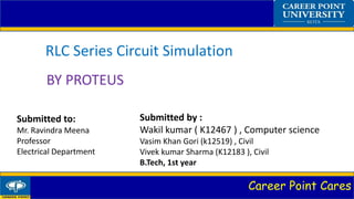
- 1. Career Point Cares RLC Series Circuit Simulation BY PROTEUS Submitted to: Mr. Ravindra Meena Professor Electrical Department Submitted by : Wakil kumar ( K12467 ) , Computer science Vasim Khan Gori (k12519) , Civil Vivek kumar Sharma (K12183 ), Civil B.Tech, 1st year
- 2. Career Point Cares CONTENT • Introduction • Working • Applications of RLC circuit
- 3. Career Point Cares Introduction An RLC circuit which is also known as resonant or tuned circuit is an electrical circuit consisting of a resistor, an inductor and a capacitor, connected in series or parallel. This configuration forms a harmonic oscillator.
- 5. Career Point Cares Working • Open the proteus software in your pc. • Choose a resistor, capacitor, inductor and an ac voltage source from the library. • The voltage source will be of 220 v and 50Hz frequency. • Connect the components in series and lastly ground them. • Now the values of voltage across every component will be calculated. • Finally the waveform will be observed through analogue Analysis.
- 7. Career Point Cares Applications • AM/FM radios with analog tuners typically use an RLC circuit to tune a radio frequency. • In oscillator circuits, it is generally used to make the damping factor as small as possible, or equivalently, to increase the quality factor (Q) as much as possible. • An overdamped series RLC circuit can be used as a pulse discharge circuit. Often it isuseful to know the values of components that could be used to produce a waveform.
- 8. Career Point Cares Reference • Kumar and Kumar, Electric circuits & Networks, page. 464 • Agarwal and Lang , Page. 692 • Nilsson and Riedel, page.303