1. Title: Biomass gasification for ammonia production
Authors: Dr Paul Gilbert, University of Manchester
Dr Patricia Thornley, University of Manchester
Ms Sarah Alexander, Aston University
Dr John Brammer, Aston University
Abstract
109 million tonnes of ammonia is produced globally each year, 85% of this is
synthesised from combining H2, produced from steam reforming of natural gas, and
nitrogen separated from air. The process is very energy intensive and releases 208
million tonnes of CO2. Production of ammonia from renewable resources, such as
biomass, could substantially reduce this. One option is to gasify biomass to produce a
hydrogen rich syngas for ammonia production. This paper reviews currently available
gasification technologies to assess the viability of ammonia production using this
method, and identifies those most suitable for further analysis. The gasifier selection
is based on the following criteria: syngas composition, efficiency, operating
conditions, scale and biomass track record. Potential process schemes are presented
with preliminary mass/energy and greenhouse gas balances to estimate the potential
value of developing such a system. Critical issues are identified in the overall system,
from biomass cultivation to ammonia production. These issues need to be evaluated
further via economic and life cycle assessment techniques.
1. Introduction
Ammonia is a fundamental chemical compound required for the production of
nitrogen based fertilisers for agriculture, horticulture and biomass. The conventional
method in producing ammonia is the Haber-Bosch process, which combines H2 from
steam reforming of natural gas and N2 from the air. 109 million tonnes of ammonia is
produced globally each year and the steam reforming process is very energy intensive,
accounting for 1.2% of the global primary energy demand (Ahlgren, Baky et al.
2008). Life cycle assessments have shown that fertiliser production can be responsible
for up to 80% of the total greenhouse gas emissions associated with biomass
cultivation systems (Elsayed and Mortimer 2001). Consequently, there is interest in
reducing the environmental impact of fertiliser production, by minimising the input of
fossil fuels. It is proposed that this could be achieved through utilising renewable
technologies such as bioenergy systems.
Thermal conversion technologies appropriate for producing hydrogen from biomass
include gasification and pyrolysis, where a hydrogen rich syngas could replace the
input of natural gas required for ammonia production. Anaerobic digestion could yield
a methane feed, which could then be converted to hydrogen in a similar fashion to the
conventional natural gas approach. Other biological advancements are reviewed
elsewhere (Ni, Leung et al. 2006). Nonetheless, the focus of this study is biomass
gasification.
2. In Europe, ammonia plants are large scale systems and typical sites operate at 1000-
1500 t/d, however more recent plants can be in excess of 1800 t/d (EFMA 2000a).
These large scales are driven by the scale economies of the high-pressure Haber-
Bosch process and the associated air separation plant for nitrogen supply. They
require a natural gas input of 23.4 MJ per kg of ammonia (EFMA 2000a). The scale
of the proposed biomass-based plant will need therefore to be commensurate, but will
in practice be constrained by the supply of biomass and by the scale of the gasification
reactor. Preliminary calculations we have carried out indicate that 1500 t/d of
ammonia would require a minimum of about 2000 dry t/d biomass. The largest
operating biomass gasifier to date consumes about 350 dry t/d biomass (Barber and
Warnken 2008) and new plant proposals commonly specify up to double this scale.
Coal gasifiers are now being designed at over 3000 t/d. Scale may also be limited by
biomass supply logistics; although a planned port-located biomass combustion plant
in the UK will process 5000 dry t/d of imported biomass (SKM 2006). Therefore it is
possible that a biomass-based ammonia plant could achieve a production rate
comparable to natural gas plants given the right scenario.
The longer-term objective of this study is to determine the environmental and techno-
economic impacts of producing biomass derived ammonia and fertiliser compared to
conventional ammonia production from natural gas. In this preliminary paper
greenhouse gas balances will be calculated to identify potential savings for a
candidate overall process scheme. Short rotation coppice (SRC) willow will be
cultivated and used as feed for gasification, whereby the gasifier is selected for its
scale-up and H2 producing attributes. The product gas will be conditioned to
maximise the hydrogen content, and if necessary further nitrogen will be added to
achieve the correct molar ratio of 3:1. Ammonia production will then take place in a
similar way to conventional ammonia production.
2. Methodology
The feasibility of producing ammonia from biomass gasification is to be assessed
using life cycle assessment (LCA) and techno-economic analysis (TEA).
2.1 Life Cycle Assessment
LCA is a methodology used to assess the environmental impact of a product or
process from cradle-to-grave. The principles and framework of LCA are described in
ISO 14040:2006 (ISO 2006). SimaPro 7.1, developed by Prě Consultants, is used to
determine the environmental impacts of the biomass scenarios compared to
conventional ammonia production (Goedkoop, Schryver et al. 2008). Ecoinvent is
used as a reference for the life cycle inventory data and for the impact assessment
methodology. The four sections of an LCA study are: goal and scope of definition,
inventory analysis, impact assessment and interpretation.
2.2 Techno-Economic Analysis
The TEA analyses the technical and economic feasibility of a specified system, which
in the case of this study will be the numerous biomass gasification processes currently
3. available. There are several methods of analysis though the preferred, as outlined by
sources such as (Bridgwater, Toft et al. 2002), is to divide the production process into
specific steps and economically evaluate each section separately. Not only does this
outline which areas of production require the largest financial input but it also
highlights any economic indicators that were not originally considered. The areas
currently being considered are feedstock preparation, gasification, gas cleaning and
ammonia production.
It is being assumed that all feedstock types enter the gasifier in the same state; hence
pre-treatment has to be considered with additional cost. Oxidising agent selection can
give rise to a high economic impact, either by entailing an upfront cost increase at the
gasification stage or throughout gas cleaning and ammonia production. The TEA will
establish the capital investment and cost of ammonia production for each process
route at a range of scales. These will then be compared to conventional ammonia
production processes.
3. System Characterisation for Ammonia Production
3.1 Conventional Ammonia Production
The reference case for this study is conventional ammonia production, which is
standard practice within industry and is described in detail by the European Fertilizer
Manufacturers Association (EFMA 2000a). The two main types of ammonia
production are steam reforming of natural gas or the partial oxidation of heavy fuel
oil. The latter technique could be transferred to utilising fast pyrolysis oil. Coal
gasification and water electrolysis are no longer used for ammonia production in
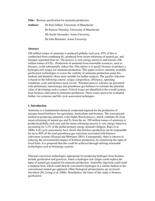
Europe. The process scheme for ammonia production from steam reforming of natural
gas has been selected as the preliminary reference case and is displayed in Figure 1.
Desulfurisation
Ammonia Synthesis
Compression
Methanation
CO2 Removal
Shift Conversion
Secondary Reformer
Primary Reformer
Natural Gas
NH3
ZnO
H2O, Fuel
Air, Power
Flue-Gas
ZnS
Heat
Heat
Heat, Power Condensate, CO2
Power
Power Heat, Purge/flash
Figure 1: Schematic of the Steam/Air Reforming Process (EFMA 2000a)
4. From an LCA perspective, the significant environmental impacts of conventional
ammonia production stem from the use of fossil fuels – natural gas as the feedstock
and heavy fuel oil as the fuel for reforming. The large consumption of natural gas
results in considerable CO2 emissions during steam reforming and shift conversion
increasing global warming potential (GWP). Approximately 1.5 kg of CO2 is emitted
to the atmosphere per kg of ammonia produced (Althaus, Chudacoff et al. 2007). CO2
emissions can be reduced through effective recovery however this depends on the
downstream facilities. The second major source of emissions arises from the flue-gas
in the primary reformer through using heavy fuel oil and could potentially lead to a
notable impact on ozone layer depletion (ODP). This could be reduced by burning
bio-diesel or additional syngas produced via biomass gasification. Finally during
operation, emissions of ammonia to water from condensates and scrubbing of waste
gases increases the impact from eutrophication and the likelihood of human and
aquatic toxicity.
3.2 Ammonia Production from Biomass
The biomass gasification system involves the cultivation of biomass, gasification and
syngas cleaning, syngas conditioning and ammonia production. Utilising biomass
gasification will address the environmental impacts of ammonia production by
reducing the need for fossil fuels. Consequently, the GWP and ODP should be lower.
The process scheme is shown in Figure 2. Syngas conditioning is regarded as the
stages involved from desulphurisation to compression in Figure 1. However, since the
H2 content will be higher from biomass gasification, it is thought that reduced power
and heat demand will be required – increasing the conversion efficiency to ammonia.
Furthermore, as the sulphur content from biomass gasification will also be lower, the
desulfurization step could be discounted. Only the significant impacts have been
included in Figure 2, as every stage will involve the release of CO2.
3.3 Overview of Process Schemes for Ammonia from Biomass
3.3.1 Willow Cultivation, Processing and Delivery
The willow cultivation scheme is based on Thornley, Upham et al. 2009 (Thornley,
Upham et al. 2009). Referring to the first three sections of Figure 2, willow is
cultivated near the gasification plant on previously arable land. At the start of ground
preparation, herbicide is applied to kill perennial weeds. Tillage is then completed to
cultivate the land so to become suitable for planting. Willow is established from
lengths of willow cane and is obtained from nursery production at local level. 15,000
willow cuttings are required to produce 29.4 odt/ha at every 3 year harvest, with a
moisture content of 50%. As a result, the average annual yield is 19.6 t/ha, as
received. Harvesting is done with a self-propelled forage harvester with a specialist
SRC header to produce 35mm wood chips. The chips are blown from the harvester
into a trailer and transported to the storage area for drying. Drying reduces the
moisture content from 50% to 30%. The chips are transported by 28 t lorry to the
gasification plant. Sewage sludge cake is applied at a rate of 20 t/ha every three years
after harvest, which is common practice for large scale sites in the UK. After
cultivation, the land is returned to its original condition.
5. Ground preparation
(tillage - ploughing
and harrowing)
Glyphosate, Diesel
Planting and cultivation
(planting, rolling)
Willow Cuttings, Sewage
Sludge, Herbicide,
Pesticide, Diesel
Harvesting and restoration
(harvest and chipping, drying,
mulching)
Glyphosate, Diesel
Transportation of willow
to gasifier
Pre-treatment
(drying and comminution)
Gasification
Syngas cleaning
(tar, particulate and
ammonium removal)
Diesel
Heat, Power,
Fuel, H2O
Steam, Air,
Power
Flue-gas, Ash
Wastewater,
Ash
Power
Syngas conditioning including
(H2 separation / CO2 removal)
Flue-gas, Heat,
CO2
Ammonia Synthesis Heat,
Purge/flash
Power
NH3
Potential Leaching
Figure 2: Schematic of Ammonia Production from Biomass Gasification
3.3.2 Potential Biomass Gasification Technologies
Currently available gasification technologies were reviewed to assess the viability of
ammonia synthesis gas production and are shown in Table 1 and the different
technologies available are discussed below. Following gasification, either hot or cold
gas cleaning will remove particulates and recycle solids and tars. To achieve a high H2
yield the syngas will be conditioned as described in section 3.3.3. The criteria used to
assess the gasifiers were: syngas composition, efficiency, operating conditions, scale
and biomass track record.
6. Table 1: Review of Existing Gasifiers for Ammonia Production from Biomass
Gasifier Fuel Syngas Composition (mol.%) LHV (MJ/m3
) Efficiency Operating Conditions Scale Hours
FICFB, Gussinga
Biomass 39% H2, 20% CO, 27% CO2,
14% CH4
14 73%gasifier,
25%e
Twin circulating fluidised bed, steam/air,
850°C
8MWinput
(4.5MWth,
2 MWe)
6,500+
SilvaGasb
Biomass 17.5% H2, 50% CO, 9.4% CO2,
15.5% CH4
18.5 40%e Twin circulating fluidised bed, steam/air,
850-1000°C
10 t/day,
200 kWe
20,000
SilvaGasb
Biomass 22% H2, 44.4% CO, 12.2% CO2,
15.6 % CH4
17.3 40%e Twin circulating fluidised bed, steam/air,
850-1000°C
182 odt/day,
50MWe
-
Foster Wheeler,
Sydkraftc
Biomass 9.5-12% H2, 16-19% CO, 14.4-
17.5% CO2, 5.8-7.5% CH4, 48-
52% N2
5.3-6.3 32%e,
83%net
Circulating fluidised bed, air, 950-1000°C 18MWinput,
6MWe, 9MWth
8,500
FW CHRISGASd
Biomass 11.79% H2, 11.86% CO, 27.92%
CO2, 8.17% CH4
5 32%e,
83%net
Circulating fluidised bed, steam/oxygen,
pressurised, 950-1000°C
18MWinput,
6MWe, 9MWth
-
Shelle
Coal 28.8% H2, 63.8% CO, 2% CO2 10.9 - Entrained flow, oxygen, pressurised,
2000°C
192 MWgross -
Texacof
Coal 37% H2, 39% CO, 21% CO2 9.1 - Entrained flow, oxygen, pressurised, 1250-
1550°C
900kWe -
E-Gasg
Coal - - - Two-stage entrained flow, oxygen,
pressurised, 1400°C
262 MWe Demonstrated
British Gas
Lurgih
Coal 29% H2, 54.6 % CO, 2.4% CO2,
7.1% CH4
12.0 - Fixed bed, steam/oxygen, pressurised, 570-
1100°C
- -
High Temp
Winkleri
Coal - - - Fluidised bed, pressurised, 800-1000°C - Co-fire
demonstrated
a
(Felder 2004; Hofbauer 2006; Jungbluth, Dinkel et al. 2007; Hofbauer, Rauch et al. b)
b
(Paisley and Overend; Paisley and Welch 2003)
c
(Stahl and Neergaard 1998; Stahl, Waldheim et al. 2004; Palonen, Anttikoski et al. 2006)
d
(Stahl, Waldheim et al. 2004; Albertazzi, Basile et al. 2005)
e
(Doctor, Molburg et al. 2001b; Zheng and Furinsky 2005)
f
(Richards 1995; Hornick and McDaniel 2002; Zheng and Furinsky 2005)
g
(Dowd 2000)
h
(Cooke and Taylor 1993; Shelton and Lyons 2000; Zheng and Furinsky 2005)
i
(Renzenbrink, Wischnewski et al.; Adlhoch, Sato et al. 2000)
7. Twin Fluidised Bed Gasification
The two types of twin-reactor fluidised beds considered were SilvaGas, developed at
FERCO Enterprises and the Fast Internal Circulating Fluidised Bed gasifier (FICFB),
developed at the University of Vienna.
The FICFB gasifier at Gussing operates as a two stage reactor, with a gasification
zone and a combustion zone. Biomass is gasified to produce a syngas and the non-
volatile components (char) are transferred with the bed material into the combustion
zone, where they are burnt completely. Heat from the combustion zone is transferred
to the gasification zone to maintain the gasification process. The 100 kWth pilot plant
was developed over 5 years in Vienna and extensive testing (1,600 hours) was
performed to determine the effect of temperature, steam/biomass ratio and bed
catalyst (Hofbauer, Rauch et al. a). Steam is used as the gasifying agent in the
gasification zone and gasification takes place at 850°C. Utilising steam results in a
low-nitrogen and low-tar syngas (1.5-2.5 g/Nm3
) prior to gas cleaning. Biomass
feedstock and moisture content could vary, and the gasifier has operated using wood
chips, annual crops and C4-energy crops, with moisture content ranging between 15-
40%. With a biomass moisture content of 15 % and a cold gas efficiency of 73 %, the
syngas composition is promising for H2 production (39 %.moldry) (Jungbluth, Dinkel
et al. 2007). A wood-chip fired 8 MWth demonstration plant was constructed in 2001
and at the end of April 2005, 6,500 hours of gasifier operation was recorded (Van der
Drift; Hofbauer, Rauch et al. b). Of the 8 MW fuel input, 4.5 MWth will be used for
district heating and 2 MWel with be the electrical output. The electrical efficiency is
25% and the total efficiency is 80% (Hofbauer 2006).
The SilvaGas gasification system operates similar to the FICFB gasifier. Nonethless,
biomass is gasified in a higher temperature region at 850-1000°C producing a medium
heating value syngas (17-19 MJ/Nm3
) (Paisley and Welch 2003). The biomass track
record is positive and the heating value and syngas concentration remain constant
with varying biomass feed. Testing of the Silvagas gasifier in the 10 ton per day
Process Research Unit was successful and over 20,000 hours operation was reported
(Paisley and Overend). The gasifier has been tested at a commercial scale
demonstration site at Burlington, Vermont and was designed for 182 dry tonnes (200
tons) per day of biomass feed. The moisture content of the wood feed ranged between
10-50% and operating at the larger scale site, the equivalent heating value was
reported lower at 11-14 MJ/Nm3
.
Circulating Fluidised Bed Gasification
Fluidised bed gasifiers have been used extensively within the coal industry, providing
uniform reactor temperatures and increased thermal efficiency compared to fixed bed
gasifiers. The other advantages include high carbon conversion, good scale-up
potential, efficient tar conversion and the production of a medium LHV syngas
(Belgiorno, De Feo et al. 2003).
Sydkraft AB produced the worlds first complete biomass fed IGCC power plant using
a pressurised CFB Foster Wheeler gasifier (Stahl and Neergaard 1998). The air-blown
8. gasifier operated at 950-1000°C and at approximately 20 bar. Biomass fuel was
inputted at 18 MW (equivalent of 4 t/hr) with a moisture content of 5-20%, which was
pre-dried using the flue gas from the gas turbine. As a result, the plant produces 6
MWe and 9 MWth with a net electrical efficiency of 32% and total net efficiency of
83%. Due to utilising air as a gasifying agent, the heating value of the syngas was 5.3-
6.3 MJ/Nm3
. The process could be optimised by increasing the O2 content through
enriched air gasification (Campoy, Gómez-Barea et al. 2009). Tests performed using a
bubbling fluidised bed gasifier have shown that increasing the O2 content from 21% to
40% (v/v) increased gasifier efficiency from 58% to 68% and the H2 content from
8.7% to 27.5%.vol dry basis. The costs were relatively low compared to utilising
O2/steam gasification.
The CHRISGAS Project is an expansion on the original Varnamo gasification
demonstration plant, aiming to produce H2-rich syngas from biomass (Stahl,
Waldheim et al. 2004). The gasifier operates at elevated pressures using steam and O2
as gasifying agents (Albertazzi, Basile et al. 2005). An oxygen blown gasifier would
integrate well with the requirement for an Air Separation Unit (ASU) to supply N2 to
the ammonia synthesis plant. Still more attractive would be to supply the gasifier with
enriched O2 air rather than pure O2; the former being much easier and cheaper to
supply from the Air Separation Unit (ASU). By an appropriate choice of O2
concentration, the synthesis gas could be delivered with the correct N:H molar ratio.
Pressurised gasification is also attractive, as it integrates well with the gas
conditioning process which for natural gas is commonly operated at 30 bar prior to
ammonia synthesis at 60-180 bar.
The high-temperature Winkler (HTW) process is a fluidised bed coal gasification
process and operates under pressure at 800-1000°C (Renzenbrink, Wischnewski et
al.). HTW gasification could be suited for biomass feeds (Adlhoch, Sato et al. 2000).
Co-gasification of pre-treated municipal solid waste (1000 tons) was demonstrated on
a commercial scale at Berrenath, Germany.
Entrained Gasification
Entrained gasifiers have been used extensively for coal gasification and successful
systems include the Texaco, Shell and E-Gas gasifiers. There has been limited
research into the successful application of biomass fed entrained gasifiers at
demonstration scale. The performance of four coal fed IGCC plants utilising Shell,
Texaco, British Gas Lurgi and Kellogg Rust Westinghouse gasifiers have been
assessed using Aspen Plus (Zheng and Furinsky 2005). The operating conditions of
the gasifiers are provided in Table 1.
The Shell gasifier receives dry coal feed and is oxygen blown, however does not have
a proven biomass track record (Doctor, Molburg et al. 2001b; Zheng and Furinsky
2005).
The Texaco gasification process has been installed at the Tampa Electric Polk Power
9. Station for IGCC (Hornick and McDaniel 2002). Texaco state that the syngas could
be used for high-purity H2 and ammonia production. Biomass co-firing has been
reported; however, the biomass would have to be prepared in a similar way to coal
through milling to a fine powder to allow injection into the reactor. During the test
period the biomass yielded 860 kW (7700 kWh total), based on heating values and
flow rates of biomass and base fuel.
The E-Gas is a coal fed, continuous slagging, two-stage entrained flow gasifier. A 262
MWe Wabash River Coal Gasification Project has been successfully demonstrated
(Dowd 2000). The gasifier has not been tested with biomass.
Fixed Bed Gasification
Updraft and downdraft fixed bed biomass gasifiers were not assessed in depth, as they
offer little control and scale-up attributes (Belgiorno, De Feo et al. 2003).
Furthermore, the conversion of tar is reported to be low in updraft gasifiers.
Nonetheless, the British Gas Lurgi (BGL) gasifier was reviewed. It is an
oxygen/steam blown, fixed bed gasifier (Cooke and Taylor 1993; Shelton and Lyons
2000).
Choice of gasification technology for further analysis
The FICFB gasifier was selected as a candidate gasifier for preliminary analysis, as it
has received successful testing with steam gasification to produce a high H2 content
syngas prior to CO2 removal. Additionally, the pilot plant is still in operation.
Extensive information on the FICFB gasifier is available online and Ecoinvent life
cycle inventory data has been published using mass and energy data based on the
Gussing plant (Reinhard 2000; Jungbluth, Dinkel et al. 2007). Alternative process
routes incorporating other gasifiers, gas conditioning options and ASU arrangements
will be selected in due course and evaluated through careful LCA and TEA.
3.3.3 Syngas Conditioning
Three options were identified as potential methods to separate hydrogen from the
syngas: CO2 removal, Pressure Swing Adsorption (PSA) and Ceramic Membranes.
Prior to the hydrogen separation step, the primary reformer converts methane and
higher hydrocarbons in the syngas to H2 and CO and the shift reactor converts CO to
H2 through the exothermic water gas shift reaction (Koroneos, Dompros et al. 2008).
In natural gas plants, these processes are commonly operated at around 30 bar.
CO2 removal
In conventional ammonia plants, syngas is passed through a reformer and shift reactor
to produce a H2 rich synthesis gas (Hamelinck and Faaij 2002). CO2 is removed in
either a chemical or physical absorption process, and traces of CO2 and CO are then
converted to CH4 through methanation and removed. In the chemical absorption
process, aqueous amine solutions are typically used, but are not regarded as the best
available technique, as the regeneration requires a large amount of energy. New
10. ammonia plants utilise the Activated Methyl DIEthanolamine (aMDEA) standard 2-
stage process (EFMA 2000a). Hydrogen content can have a purity of up to 98 %, with
the remainder comprising typically of N2.
CO2 removal through chemical absorption with biomass gasification has been the
subject of previous studies (Corti and Lombardi 2004; Carpentieri, Corti et al. 2005).
The extent that CO2 emissions were reduced in a biomass combined gasification cycle
was determined using performance analysis and LCA. Nonetheless, the focus of these
studies was not to maximise hydrogen yield. Since the ammonia synthesis from
biomass will be similar to conventional synthesis from natural gas, critical issues to
ensure successful conversion include the clean-up steps for tar, sulphur and ash prior
to reforming.
Pressure Swing Adsorption
To improve H2 purity, pressure swing adsorption (PSA) should be considered as an
alternative to CO2 removal. PSA is based on the different adsorption characteristics of
different molecules. The process passes the H2 rich synthesis gas over several beds,
which in turn extract impurities, CO2 and H2O. The resultant syngas is extremely pure
and H2 yield can be as high as 99.999% (Hamelinck and Faaij 2002). If all the gas is
not converted it can be recycled after passing through the beds. However, recycled gas
requires recompression and cooling, which will increase capital and operational costs.
Ceramic Membrane
Ceramic membranes are an attractive option for H2 separation, as they combine shift
and separation in one reactor – simplifying the design requirements. The technology
relies on the mobility of compounds through a surface, based on a difference between
the partial gas densities. Furthermore, the physical and chemical interaction of the
gases with the membrane will affect the rate at which they are transported through.
The use of membranes for H2 separation is currently an advanced option (Page 7 from
(Hamelinck and Faaij 2002)). Hamelinck and Faaij go on to discuss the removal of the
shift reactor due to the membrane surface catalysing the water gas shift reaction –
although data released on this was stated as being largely confidential.
Ceramic membranes are capable of operating over a wide temperature and pressure
range, and are easier to manufacture compared to PSA technologies. In addition, with
a reduction in the requirement for heat exchangers, efficiency losses are reduced and
capital costs are lower ((Williams 1998) from (Hamelinck and Faaij 2002)). In a LCA
study to determine the feasibility of producing ammonium nitrate fertiliser from
biomass, ceramic membranes were utilised to separate hydrogen (Ahlgren, Baky et al.
2008).
To produce a hydrogen rich feed for ammonia synthesis, CO2 removal was chosen for
this preliminary analysis. CO2 removal was regarded as being established and proven,
and could operate at the required scale to produce an adequate feed of H2. PSA would
result in increased costs for the system, and ceramic membranes were considered to
11. be in the developing stages, therefore would not be a true representation of the current
best available technologies. They may be evaluated later in the work programme.
3.3.3 Ammonia Synthesis
Once the syngas is fully conditioned and contains the required purity of H2 (together
with up to the correct amount of N2 in some process configurations), it is necessary to
add the necessary remaining N2 to achieve the correct molar ratio (supplied from the
ASU) and then proceed to the ammonia synthesis step. This is the well-known Haber-
Bosch process, commonly operated at between 60 and 180 bar and thus requiring the
synthesis gas to be compressed.
4. Mass and Energy Balances
A preliminary mass and energy balance was completed. At a conventional ammonia
production plant, 35.1 GJ of natural gas feedstock is required to produce 1500 t/d of
ammonia (Althaus, Chudacoff et al. 2007). Considering the biomass scenario, the H2
content in the syngas is higher than the H2 content in natural gas. Consequently, the
process should be more efficient in converting the syngas into H2 during conditioning.
Using the Gussing syngas composition in Table 1, and assuming a gasifier cold gas
efficiency of 73% and syngas net heating value of 14 MJ/Nm3
(Jungbluth, Dinkel et
al. 2007), a minimum of 2000 t/d dry biomass is required to produce 1500 t/d of
ammonia. This assumes that H2 conversion is maximised in the reformer and all the
CO is converted to H2 during the water gas shift reaction. In reality, this will not be
the case, and LCA and TEA is therefore required to produce a detailed mass and
energy balance to understand the environmental impacts and technicalities of the
process. This will be the focus of the work programme within Supergen Bioenergy.
5. Environmental Impacts
5.1 Greenhouse Gas Balance
Switching to a H2 rich feedstock from biomass gasification will reduce the impact of
CO2 emissions by minimising natural gas input. Therefore, the resultant GWP will be
lower from ammonia synthesis. If bioenergy is used as the fuel for the primary
reformer, GWP and ODP impacts will reduce further. The main contributors for GHG
emissions will now stem from biomass cultivation and gasification. Nitrous oxide
emissions from applying fertilisers to the soil, and the use of diesel for the operation
of agricultural machinery and tractors during cultivation will be significant (Ahlgren,
Baky et al. 2008). Furthermore, transportation of inputs required for cultivation and
gasification, and delivery of willow to the plant will increase the GWP. As ammonia
produced from biomass may operate at a smaller scale, expected plant output will be
investigated to determine its effect on GHG emissions. TEA will look at different
scales of operation to establish the most economic configurations and the GWP of the
most promising will be evaluated.
5.2 Other Environmental Impacts
The other environmental issues that will be identified through LCA are acidification,
12. eutrophication, abiotic depletion and human and fresh water toxicity. The levels of
eutrophication and acidification are expected to increase due to cultivation, in
comparison to using natural gas (Heller, Keoleian et al. 2003; Brentrup, Küsters et al.
2004b; Ahlgren, Baky et al. 2008). From initial LCA work, nitrogen and phosphorous
leaching from the sewage sludge application are thought to contribute the most to
eutrophication, and acidification potential is thought to increase from nitrous oxide
emissions from the use of diesel in the tractors. Evaluation of other cultivation
strategies will therefore also be evaluated, possibly including utilisation of the
biofertiliser for biomass growth. Increasing the intensity of biomass cultivation will
result in higher NH3 emissions to soil (Brentrup, Küsters et al. 2004b). Finally, careful
consideration must be taken for the environmental impacts occurring from the
disposal of ash from the gasifier.
6. Conclusions
Existing gasifiers and gas conditioning technologies were reviewed for ammonia
production from biomass gasification. The FICFB gasifier with CO2 removal was
selected as the preliminary strategy suitable for producing a hydrogen rich syngas.
Detailed LCA should now be completed, as the preliminary calculations suggest that
considerable savings could be made on greenhouse gas emissions, arising from the
reduced usage of fossil fuels. Furthermore, LCA would highlight the potential
environmental impacts of acidification and eutrophication from the use of fertilisers
and pesticides during biomass cultivation. The next stage of work will focus on
completing mass and energy balances and greenhouse gas balances of the selected
process scheme to develop a detailed LCA and TEA.
13. References
Adlhoch, W., H. Sato, et al. (2000). High-temperature Winkler gasification of
municipal solid waste. 2000 Gasification Technologies Conference, San Francisco,
California.
Ahlgren, S., A. Baky, et al. (2008). "Ammonium nitrate fertiliser production based on
biomass - Environmental effects from a life cycle perspective." Bioresource
Technology 99(17): 8034-8041.
Albertazzi, S., F. Basile, et al. (2005). "The technical feasibility of biomass
gasification for hydrogen production." Catalysis Today 106(1-4): 297-300.
Althaus, H., M. Chudacoff, et al. (2007). Life Cycle Inventories of Chemicals, Final
Report Ecoinvent v2.0 No. 8. Duebendorf, CH, Swiss Centre for Life Cycle
Inventories.
Barber, M. and M. Warnken (2008). Biomass Technology Review: Processing for
Energy and Materials, Crucible Carbon.
Belgiorno, V., G. De Feo, et al. (2003). "Energy from gasification of solid wastes."
Waste Management 23(1): 1.
Brentrup, F., J. Küsters, et al. (2004b). "Environmental impact assessment of
agricultural production systems using the life cycle assessment (LCA) methodology
II. The application to N fertilizer use in winter wheat production systems." European
Journal of Agronomy 20(3): 265-279.
Bridgwater, A. V., A. J. Toft, et al. (2002). "A techno-economic comparison of power
production by biomass fast pyrolysis with gasification and combustion." Renewable
and Sustainable Energy Reviews 6(3): 181-246.
Campoy, M., A. Gómez-Barea, et al. (2009). "Air-steam gasification of biomass in a
fluidised bed: Process optimisation by enriched air." Fuel Processing Technology
90(5): 677-685.
Carpentieri, M., A. Corti, et al. (2005). "Life cycle assessment (LCA) of an integrated
biomass gasification combined cycle (IBGCC) with CO2 removal." Energy
Conversion and Management 46(11-12): 1790-1808.
Cooke, B. H. and M. R. Taylor (1993). "The environmental benefit of coal
gasification using the BGL gasifier." Fuel 72(3): 305-314.
14. Corti, A. and L. Lombardi (2004). "Biomass integrated gasification combined cycle
with reduced CO2 emissions: Performance analysis and life cycle assessment (LCA)."
Energy 29(12-15): 2109-2124.
Doctor, R., J. Molburg, et al. (2001b). Life-cycle analysis of a Shell gasification-based
multi-product system with CO2 Recovery. The First National Conference on Carbon
Sequestration, Washington DC.
Dowd, R. (2000). Wabash River Coal Gasification Repowering Project Final
Technical Report. Morgantown, West Virginia, The U.S. Department of Energy
Office of Fossil Energy National Energy Technology Laboratory.
EFMA (2000a). Best Available Techniques for Pollution Prevention and Control in
the European Fertilizer Industry. Booklet No.1: Production of Ammonia. Brussels,
European Fertilizer Manufacturers Association.
Elsayed, M. and N. Mortimer (2001). Carbon and Energy Modelling of Biomass
Systems: Conversion Plant and Data Updates. Final Report: B/U1/00644/00/00,
Sheffield Hallam Univerity.
Felder, R. (2004). Ecological impact of the use of methane from wood gasification.
Internal report within the Ecogas project. Villigen, Switzerland, Paul Scherrer
Institute (PSI).
Goedkoop, M., A. Schryver, et al. (2008). Introduction to LCA with SimaPro 7, PRe
Consultants.
Hamelinck, C. N. and A. P. C. Faaij (2002). "Future prospects for production of
methanol and hydrogen from biomass." Journal of Power Sources 111(1): 1-22.
Heller, M. C., G. A. Keoleian, et al. (2003). "Life cycle assessment of a willow
bioenergy cropping system." Biomass and Bioenergy 25(2): 147-165.
Hofbauer, H. (2006). Gas-cleaning at the Gussing plant update. ThermalNet, Lille.
Hofbauer, H., R. Rauch, et al. (a). Hydrogen Rich Gas from Biomass Steam
Gasification. Vienna, Institute of Chemical Engineering, Fuel and Environmental
Technology.
15. Hofbauer, H., R. Rauch, et al. (b). Six years experience with the FICFB-Gasification
Process. Vienna, Institue of Chemical Engineering.
Hornick, M. and J. McDaniel (2002). Tampa electric polk power station integrated
gasification combined cycle project - Final technical report. Morgantown, West
Virginia, The U.S. Department of Energy, National Energy Technology Laboratory.
ISO (2006). Environmental management — Life cycle assessment — Principles and
framework. Geneva, International Standard Organization BS EN ISO 14040:2006.
Jungbluth, N., F. Dinkel, et al. (2007). Life Cycle Inventories of Bioenergy, Ecoinvent
report No. 17. Dubendorf, CH, Swiss Centre for Life Cycle Inventories.
Koroneos, C., A. Dompros, et al. (2008). "Hydrogen production via biomass
gasification--A life cycle assessment approach." Chemical Engineering and
Processing: Process Intensification 47(8): 1261-1268.
Ni, M., D. Y. C. Leung, et al. (2006). "An overview of hydrogen production from
biomass." Fuel Processing Technology 87(5): 461-472.
Paisley, M. and R. Overend Verification of the Performance of Future Energy
Resources’ SilvaGas® Biomass Gasifier - Operating Experience in the Vermont
Gasifier, Future Energy Resources Corporation.
Paisley, M. and M. Welch (2003). Biomass gasification combined cycle opportunities
using the future energy Silvagas gasifier coupled to Alstom's industrial gas turbines.
AMSE Turbo Expo Land, Sea and Air, Georgia World Congress Center.
Palonen, J., T. Anttikoski, et al. (2006). The Foster Wheeler gasification technology
for biofuels: refuse-derived fuel (RDF) power generation. PowerGen Europe.
Reinhard, R. (2000). "FICFB." from www.ficfb.at/.
Renzenbrink, W., R. Wischnewski, et al. High temperature Winkler (HTW) coal
gasification - A fully developed process for methanol and electricity production.
Richards, M. (1995). Texaco Gasification Process, Innovative Technology Evaluation
Report. Cincinnati, Ohio, National Risk Management Research Laboratory, U.S.
Environmental Protection Agency.
16. Shelton, W. and J. Lyons (2000). British Gas / Lurgi Gasifier IGCC Base Cases, EG
and G.
SKM (2006). Port Talbot Renewable Energy Plant. Glasgow, Sinclair Knight Merz.
Stahl, K. and M. Neergaard (1998). "IGCC power plant for biomass utilisation,
värnamo, Sweden." Biomass and Bioenergy 15(3): 205-211.
Stahl, K., L. Waldheim, et al. (2004). Biomass IGCC at Varnamo, Sweden - Past and
future. GCEP Energy Workshop, Frances C. Arrillaga Alumni Center, Stanford
University, California.
Thornley, P., P. Upham, et al. (2009). "Integrated assessment of bioelectricity
technology options." Energy Policy 37(3): 890-903.
Van der Drift, B. Status of biomass gasification, Energy Reseach Centre of the
Netherlands.
Williams, R. (1998). Cost-competitive Electricity from Coal with Near-zero Pollutant
and CO2 Emissions. Review - Draft. Princeton, PU/CEED.
Zheng, L. and E. Furinsky (2005). "Comparison of Shell, Texaco, BGL and KRW
gasifiers as part of IGCC plant computer simulations." Energy Conversion and
Management 46(11-12): 1767-1779.