Lighting Automation- A Web-Based Approach
•
1 gostou•306 visualizações

The research paper showcases the efficiency and reliability of the prototype developed for Danson Lighting Pvt. Ltd. The Lighting Automation is achieved through the use of ZigBee for communication.

Recomendados
Recomendados
Mais conteúdo relacionado
Mais procurados
Mais procurados (13)
Destaque
Semelhante a Lighting Automation- A Web-Based Approach
Semelhante a Lighting Automation- A Web-Based Approach (20)
Último
Último (20)
Lighting Automation- A Web-Based Approach
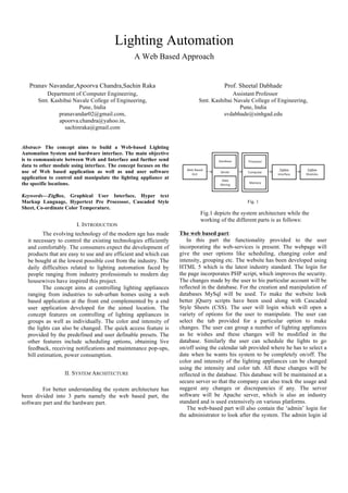
- 1. Lighting Automation A Web Based Approach Pranav Navandar,Apoorva Chandra,Sachin Raka Department of Computer Engineering, Smt. Kashibai Navale College of Engineering, Pune, India pranavandar02@gmail.com, apoorva.chandra@yahoo.in, sachinraka@gmail.com Prof. Sheetal Dabhade Assistant Professor Smt. Kashibai Navale College of Engineering, Pune, India svdabhade@sinhgad.edu Abstract- The concept aims to build a Web-based Lighting Automation System and hardware interface. The main objective is to communicate between Web and Interface and further send data to other module using interface. The concept focuses on the use of Web based application as well as and user software application to control and manipulate the lighting appliance at the specific locations. Keywords—ZigBee, Graphical User Interface, Hyper text Markup Language, Hypertext Pre Processor, Cascaded Style Sheet, Co-ordinate Color Temperature. I. INTRODUCTION The evolving technology of the modern age has made it necessary to control the existing technologies efficiently and comfortably. The consumers expect the development of products that are easy to use and are efficient and which can be bought at the lowest possible cost from the industry. The daily difficulties related to lighting automation faced by people ranging from industry professionals to modern day housewives have inspired this project. The concept aims at controlling lighting appliances ranging from industries to sub-urban homes using a web based application at the front end complemented by a end user application developed for the aimed location. The concept features on controlling of lighting appliances in groups as well as individually. The color and intensity of the lights can also be changed. The quick access feature is provided by the predefined and user definable presets. The other features include scheduling options, obtaining live feedback, receiving notifications and maintenance pop-ups, bill estimation, power consumption. II. SYSTEM ARCHITECTURE For better understanding the system architecture has been divided into 3 parts namely the web based part, the software part and the hardware part. Fig. 1 Fig.1 depicts the system architecture while the working of the different parts is as follows: The web based part: In this part the functionality provided to the user incorporating the web-services is present. The webpage will give the user options like scheduling, changing color and intensity, grouping etc. The website has been developed using HTML 5 which is the latest industry standard. The login for the page incorporates PHP script, which improves the security. The changes made by the user to his particular account will be reflected in the database. For the creation and manipulation of databases MySql will be used. To make the website look better jQuery scripts have been used along with Cascaded Style Sheets (CSS). The user will login which will open a variety of options for the user to manipulate. The user can select the tab provided for a particular option to make changes. The user can group a number of lighting appliances as he wishes and these changes will be modified in the database. Similarly the user can schedule the lights to go on/off using the calendar tab provided where he has to select a date when he wants his system to be completely on/off. The color and intensity of the lighting appliances can be changed using the intensity and color tab. All these changes will be reflected in the database. This database will be maintained at a secure server so that the company can also track the usage and suggest any changes or discrepancies if any. The server software will be Apache server, which is also an industry standard and is used extensively on various platforms. The web-based part will also contain the ‘admin’ login for the administrator to look after the system. The admin login id
- 2. and password will be different than that of the user and will contain additional features as compared to that of the user id as the admin can control and manipulate the entire system. The admin can monitor user activity and can provide maintenance. The admin and add and delete the appliance according to the users need. The Software part: In this the software will communicate with the hardware. It is somewhat like an interface between the website and the hardware. The user commands need to translate into ZigBee recognized codes. The GUI for the software will be developed using Visual Basic (VB), which is also an industry leading standard. The basic coding for the ZigBee will be done using breakthrough code. Obtaining values from the micro- controller for each of the order given by the user through the software will be in binary form, which then will be transferred to the database for further processing. The login form will contain functionalities for user and admin login. After selecting the type of login the respective form will be loaded which will provide the respective functionalities depending on the type of login. The user can directly access the functionalities like grouping, color and intensity options etc. The admin at the other end has to select which user he wants to manipulate and then he has access to all the functions that the user has and also the maintenance options. The admin part of the software will have a graphical image of a room in which he an option to add appliances directly at the socket in the room as the image will show the socket positions. This will give the admin a simpler and easy to add and remove appliance in a particular working place. Similarly the user will also have a graphical image to control the appliance rather than selecting the appliance from a list box or a drop down box. The software will be connected a database of which we will be using to store the data of all the appliances similar in way we will be doing it in the web-based application. The database will store the number of appliances, the working place data, the MAC addresses of all the appliances for the controlling. It will also save the current status of the appliance as well as the groups, presets and the calendar data into it. The User’s profile will also be saved on the database and login details of user as well as of the admin. The Hardware part: The hardware components will basically incorporate the following: 1. ZigBee Transmitter 2. ZigBee Receiver 3. Appliances 4. Development Board 5. Micro-controller The ZigBee works on RF(radio frequency) and hence can communicate wirelessly. The ZigBee is a low cost, low power, wireless mesh network standard. The low cost allows to be widely deployed in automation applications. Lower power usage allows longer life. Mesh networking provides high reliability and more extensive range. ZigBee builds upon the physical layer and media access control defined in IEEE standard 802.15.4 for low rate WPAN’s. The specification goes on to the complete standard by adding 4 main components namely, network layer, application layer, ZigBee device objects and manufacturer defined application objects which allow customization and favor total integration. The user will send the information, which will include the changes he wants to make using the web-based part and then this information will be stored at server will further forward this information to the end user machine where the software part will play its role. It will act as in interface and for this information to the ZigBee controller in ZigBee recognizable format. The ZigBee controller in turn will communicate with the ZigBee modules. At this point of time the micro-controllers will come into effect, as they are required to encode as well as decode the information sent and received. All this communication will be bi-directional and will make it easier and better as well as efficient. Fig. 2 Fig.2 depicts the ZigBee cluster interacting with other system components. As shown in fig.2 the dotted bi-directional lines denote a wireless connection while the solid bi-directional lines denote wired connections. Blocks M1, M2, M3, M4, M5, denote the ZigBee modules. The block µC denoted the micro- controller ATmega16. The block M1 acts as a ZigBee controller, which is an interface for sending and receiving data between the micro-controller and the other ZigBee modules. The other ZigBee modules mark the end appliances. All the ZigBee modules are to be function set in ZigBee ROUTER/END DEVICE AT mode and the parameters to be set are PAN ID which must be same for all the ZigBee modules in the network, Destination Address Low which must be set to 0 for router mode and Baud Rate which must be same for all the modules in the network, for example, 9600. The ZigBee modules to be used will be Digi International XBEE series 2 OEM RF modules.
- 3. III. SYSTEM FEATURES The system features of the project cover a vast control operation, which incorporates the controls and manipulation techniques like grouping, scheduling, bill estimation etc. Grouping 1. The functionality of this feature is to group together the different lighting appliances as the user wishes to group. 2. The user can group the lighting appliances and form different presets; also the default presets will be provided that the user can configure as he wishes. Color and Intensity 1. The user can change the color and intensity of the lighting appliances that are grouped together or individual lighting appliance. 2. The user can also make a preset of his color and intensity preferences given earlier. Scheduling Options 1. The user can schedule the application to do a certain task at a particular date and time. 2. Calendar and timer options are to be provided. ZigBee Interface and Module 1. ZigBee Technology enables the system to be operated wirelessly. 2. ZigBee is efficient for communicating with other ZigBee modules and the mac address of each ZigBee module can be used as an entry in the database for each lighting appliance. Live Feedback 1. This feature enables the estimation of current electricity consumption. 2. This also will help in calculation of estimated bill. Maintenance Pop-ups 1. This feature alerts the user for any possible maintenance issues that might occur in the future. 2. This feature will also alert the administrators so that they are ready with new appliance if replacement is required. Web based application 1. This feature makes it possible for the user to control the lighting appliances using the web page as well as from the end user application that will be installed at the location of the appliances. 2. The application being web based enables the user to control every appliance from anywhere using a computer with an Internet connection. Efficient ZigBee 1. ZigBee reduces our power consumption, as it is energy efficient. 2. ZigBee is also compact in design reduces our space requirement. RGB Model 1. The RGB Model gives us a varied choice of colors, which the user can have, in his place. 2. Hue saturation gives customer another versatile means to change colors. IV. PROJECT IMPLEMENTATION Fig. 3 Fig.3 depicts the GUI of the software being implemented at the user end. The tree view shows various lighting appliances being installed at user end and sorted according to the floor number and room number. The grid view shows the status of the appliances, the color values, the intensity, the group-id, the group status, the CCT value, the floor number and the room number. The control panel on the right is used to change the values of CCT, to change the status of the selected appliance, and the color values. The buttons at the bottom are used to configure the hardware part and perform operations like selecting a layout of the room, adding an appliance, deleting an appliance, and adding an appliance to a group. V. ENHANCEMNETS This type of automation system is mainly used for home automation systems. Its future scope also involves controlling robo-arms or octo-copters. It can be used in factories where high load requirement is not present. It can be used for communication where a bit of noise disturbance is tolerable, as the ZigBee devices being used are not totally immune to noise. This project can also be further developed for mobile platforms so as to achieve greater mobility. The future scope of the project can also be extended to control each and every home appliance, which may include fans, air conditioners, or even kitchen appliances. VI. Conclusion This paper has shown the ability of technology to help to communicate between Web-based Lighting Automation System and hardware interface for the same.
- 4. It has also investigated how the innovative use of existing technologies can benefit sub-urban homes, industrial, residential areas, and commercial fields. It has also provided a valuable insight into designing human computer interfaces for different audiences. VII. ACKNOWLEDGEMENT We take this opportunity to express our sincere gratitude to all the people who have contributed towards the successful completion of our project. We would like to extend our deepest and heartfelt gratitude to our project guide Prof. Mrs. S.V. Dabhade and acknowledge her able guidance and constant encouragement, which went a long way ensuring our success. We sincerely acknowledge the invaluable support and guidance extended to us by Prof. P.N. Mahalle, Head of Computer Engineering Department for nurturing a congenial yet competitive environment in the department. VIII. REFERENCES 1. Gill, K.; Shuang-Hua Yang; Fang Yao; Xin Lu, “A zigbee-based home automation system,” IEEE Transactions on Consumer Electronics, Volume 55, Issue 2, Pages 422-430, December 2009. 2. Tsang, K.F.; Lee, W.C.; Lam, K.L.; Tung, H.Y.; Kai Xuan, “An integrated ZigBee automation system: An energy saving solution,” 14th International Conference on Mechatronics and Machine Vision in Practice, IEEE Conference Publications, Pages 252- 258, 2007. 3. Siddiqui, A.A. ; Ahmad, A.W. ; Hee Kwon Yang ; Chankil Lee, “ZigBee based energy efficient outdoor lighting control system,” 14th International Conference on Advanced Communication Technology (ICACT), IEEE Conference Publications, Pages 916-919, 2012. 4. Thatti, K. ; Manikanta, K.B. ; Chhawchharia, S. ; Marimuthu, R., “ZigBee and ATmega32 based wireless digital control and monitoring system For LED lighting,” International Conference on Information Communication and Embedded Systems (ICICES), IEEE Conference Publications, Pages 878-881, 2013. 5. Yin Jun ; Wang Wei, “LED Lighting Control System Based on the Zigbee Wireless Network,” International Conference on Digital Amnufacturing and Automation (ICDMA), IEEE Conference Publications, Pages 892-895, 2010.