Analyzing performance of zrp by varying node density and transmission range
•
1 gostou•774 visualizações

International peer-reviewed academic journals call for papers, http://www.iiste.org

Recomendados
Recomendados
Mais conteúdo relacionado
Mais procurados
Mais procurados (13)
Semelhante a Analyzing performance of zrp by varying node density and transmission range
Semelhante a Analyzing performance of zrp by varying node density and transmission range (20)
Mais de Alexander Decker
Mais de Alexander Decker (20)
Último
Último (20)
Analyzing performance of zrp by varying node density and transmission range
- 1. Network and Complex Systems ISSN 2224-610X (Paper) ISSN 2225-0603 (Online) Vol.3, No.9, 2013 www.iiste.org Analyzing Performance of ZRP by Varying Node Density and Transmission Range Mr. Vishal A. Polara (M.E. Student) Department of Computer Science and Engineering Parul Institute of Engineering and Technology Vadodara,Gujarat,India E-mail: vishalpolara@gmail.com Prof. Jwalant B. Baria Department of Computer Science and Engineering Parul Institute of Engineering and Technology Vadodara,Gujarat,India E-mail: jwalant.baria@gmail.com Abstract Mobile Ad hoc Network (MANET) is a collection of mobile nodes that are arbitrarily located so that the interconnections between nodes are dynamically changing. In MANET mobile nodes forms a temporary network without the use of any existing network infrastructure or centralized administration. Each node participating in the network acts both as host and a router and must therefore is willing to forward packets for other nodes. For this purpose, a routing protocol is needed. A routing protocol is used to find routes between mobile nodes to facilitate communication within the network. The Zone Routing Protocol (ZRP) is a hybrid routing protocol for MANET which combines the advantages of the proactive and reactive approaches by maintaining an up-to-date topological map of a zone centered on each node. I am going to do simulation based study in order to analyze performance of ZRP protocol and I use Network Simulator (NS-2) tool to analysis performance of ZRP and analysis by varying node density and transmission range on different parameter like throughput, average end to end delay, and Normalized Routing load. Keywords:Routing Protocols, ZRP, Proactive Routing, Reactive Routing, Hybrid Routing. 1. Introduction The wireless network can be classified into two types: Infrastructure or Infrastructure less. In Infrastructure wireless networks, the mobile node can move while communicating, the base stations are fixed and as the node goes out of the range of a base station, it gets into the range of another base station. In Infrastructure less or Ad Hoc wireless network, the mobile node can move while communicating, there are no fixed base stations and all the nodes in the network act as routers. The mobile nodes in the Ad Hoc network dynamically establish routing among themselves to form their own network ‘on the fly’. Ad-hoc networks are also capable of handling topology changes and malfunctions in nodes. It is fixed through network reconfiguration. The routing protocol has two main functions, selection of routes for various source-destination pairs and the delivery of messages to their correct destination. The second function is conceptually straightforward using a variety of protocols and data structures (routing tables). This report is focused on selecting and finding routes. This paper contains all the detail about ZRP protocol and the result generate from various scenarios taken for simulation with conclusion and also mentions the parameter use for generating the result. 2. Overview of Protocol Here basic overview of protocol and how it work is given. Proactive routing uses excess bandwidth to maintain routing information, while reactive routing involves long route request delays. Reactive routing also inefficiently floods the entire network for route determination. so Now ZRP is used mechanism of both the type of protocol and provide better way for successfully transmitting packet from source to destination. ZRP can be categorized as a flat protocol because the zones overlap. Hence, optimal routes can be detected and network congestion can 21
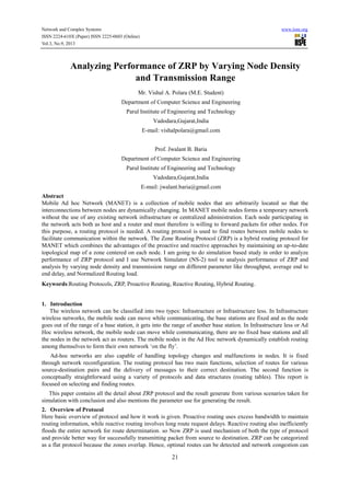
- 2. Network and Complex Systems ISSN 2224-610X (Paper) ISSN 2225-0603 (Online) Vol.3, No.9, 2013 www.iiste.org be reduced. Further, the behavior of ZRP is adaptive. The behavior depends on the current configuration of the network and the behavior of the users. 2.1 IntrAzone Routing Protocol (IARP) Here, Routing Zone of Node Is defined as a minimum distance in hops from node.so zone is not a physical distance but it is by means of hope (ρ). Here there are two type of nodes are there, Interior node and peripheral node. The node that is at the boundary of the source node is called peripheral node and the node whose distance is less than hope is called interior node. Here each and every node proactively maintains routing information of other node and it will also store request. It will use Bordercast Resolution Protocol in order to send the request to the destination node. Let’s take an example how exactly IARP work. Here Node A is source node and node k is destination node. A want to send packet to node K but it is not in the range of Node A. here In node which is in the range of Node A are Node C,B which is interior Node and Node E,F,G,H are Peripheral Node. Here Node A will send packet to Node H using BRP in order to successfully transmit packet to Node K Example will continue in section 2.2. C G I H A D J B E F K Figure 1 Example of ZRP 2.2 IntErzone Routing Protocol (IERP) This protocol reactively maintains information about the entire node which is in the range of node. It will also take information from IARP about the node and network. Now the task of IERP is to forward packet using Bordercast tree to the destination node. Here it will maintain path from source to destination reactively. Now continue with example now H will send packet using IERP to Node I so now Node K is in the Range of Node I so it will send the packet to the Node K. now as usual it will do the reverse process from Node K to Node A. 2.3 Bordercast Resolution Protocol The task of BRP protocol is to forward IERP route queries to the peripheral node of the border casting node. It will save the network resource by using cache mechanism. It will cache the route query before forwarding it to the other node. If the receiving node is a peripheral node of the previous bordercaster, then this node becomes a new bordercaster and its interior nodes are marked as covered. When BRP receive request it will send to the peripheral node and if it is interior then mark as pheripheral.it will also do reverse process of sending packet from destination to source. The BRP packet contains the query source and destination addresses, the query ID and previous bordercaster address. The route request is transported as an encapsulated packet. BRP utilizes the routing table and link state table of IARP. In addition, it uses a cache of detected queries, containing the query source, the query ID, the BRP cache ID and the previous bordercaster. The query coverage map contains a graph for every combination of query source and query ID. 3. Simulation Methodology NS-2 has been used to analyze the performance of Zone Routing Protocol under various scenarios. In Tables 1 and Table 2 give all the detail about the parameters used in the communication and movement models for simulation. 3.1 Communication Model The simulator assumes constant bit rate (CBR) traffic with a transmission rate of 4, 8, 12, 15, 20 packets per second. The number of nodes varies from 25 to 150 and Transmission Range 250 and 500. 22
- 3. Network and Complex Systems ISSN 2224-610X (Paper) ISSN 2225-0603 (Online) Vol.3, No.9, 2013 www.iiste.org Table 1 Parameters of Communication Model Parameter Value Traffic type CBR Number of Nodes 25,50,75,100,150 Transmission Range 250,500 4,8,12,15,20 packets/second Transmission Rate 3.2 Movement Model The simulation assumes a Random Waypoint Model, where a node is allowed to move in any direction arbitrarily. The nodes select any random destination in the 800 X 800 space and moves to that destination at a speed distributed uniformly between 1 and nodes maximum speed varies from 20 to 90 m/s. Upon reaching the destination, the node pauses for 20 to 120 for different scenario under constant node of 50, selects another destination, and proceeds there as discussed above. This behavior repeats throughout the duration of the simulation (500 seconds). Meanwhile, number of nodes has been varied to compare the performance of the protocols for low as well as high density environment. Table 2 lists the movement parameters of the simulations. Table 2 Parameters of Movement Model Parameter Value Simulator NS-2 Simulation Time 500 Seconds Area-of-Network 800 x 800 m No of Nodes 25,50,75,100,150 Pause Time Maximum Speed of Nodes Mobility Model 20,40,60,90,120 second 20,40,60,90 m/s Random Waypoint 3.3 Performance Metrics Three performance metrics have been measured for the protocols: 3.3.1 Throughput: Throughput means the ratio of total number of packet received in given time period. Factors that affect throughput include frequent topology changes, unreliable communication, limited bandwidth and limited energy, Update message. Throughput = Re ceived _ packet _ size Time _ to _ send 3.3.2 Average End-to-End Delay: It is the ratio of difference between time required to send packet and time required to receive packet and total received time. Delays due to route discovery, queuing, propagation and transfer time are included metric. n (CBRSentTim e CBR Re cvTime) Avg_e2e_Delay= i n (CBR Re cvTime) i 3.3.3 Normalized Routing Load: Normalized Routing Load is the ratio of total number of routing packet received and total number of data packets received [8]. NRLoad= Number _ of _ Routing _ pkts _ received Number _ of _ Data _ pkts _ received 23
- 4. Network and Complex Systems ISSN 2224-610X (Paper) ISSN 2225-0603 (Online) Vol.3, No.9, 2013 www.iiste.org 4. Implemenatation Methodology 4.1 Network Scenario and Traffic Generating 4.1.1 Network Scenario Generation: In order to generate network scenario I have used CMU generator provided by NS-2. It is under $ns-allinone2.33/indep-utils/cmu-scen-gen/setdest. But, before we use it, we need first run “make” to create executable “setdest” program. The way we write command is: ./setdest [-n num_of_nodes] [-p pausetime] [-s maxspeed][-t simtime] [-x maxx] [-y maxy] > [scenario_output_file] For example, if the command we use is like: ./setdest -n 25 -p 20.0 -s 20.0 -t 500 -x 800 -y 800 > scen25 This means, the topology boundary is 800m X 800m, the scenario has 25 nodes with nodes’ max moving speed of 20.0m/s and the pause between movements is 20s. Also, Simulation will stop in 500s, and finally, output the generate tcl statements into file whose name is scen25. 4.1.2 Network Traffic Generating: In order to generate network traffic we use cbrgen.tcl which is also provided by ns2 under $ns-allinone2.33/indep-utils/cmu-scen-gen/cbrgen.tcl. Since this can be easily read and modified, if you want, you can just simply modify it so that the scenario be generated will be more suitable to what your need. Here we can create different type of traffic like TCP or CBR for connectionless or conneftion oriented network ns cbrgen.tcl [-type cbr/tcp] [-nn nodes] [-seed seed][-mc connections] [-rate rate] Here, “-type cbr/tcp” means define the type of traffic connection, “-nn nodes” means the number of nodes could be used, “-mc connections” means maximum number of connections to be setup between those nodes,“seed seed” means a random seed, if it not equal to 0,the traffic pattern will reappear if all the other parameters are the same. “-rate rate” means a rate whose inverse value is used to compute the interval time, which easily to say is packets sending rate. For an example: ns cbrgen.tcl -type cbr -nn 25 -seed 1.0 -mc 12 -rate 8.0> cbr25 . Means create a CBR connection pattern between 25 nodes, having maximum of 20 connections, with a seed value of 1.0 and a rate of 8.0 packets/second. 5. Simulation Result Analysis Here all the analysis simulation scenario of ZRP is under constant zone radius of 2, constant area of 800m X 800m and model assume to random waypoint for node mobility. Detail parameters are given under table 1 and table 2. 5.1 Impact of Node Pause Time Figure 2, 3 and 4 shows the result obtained from varying Pause time of nodes from 20s to 120s and no of nodes are 50. Figure 2 Analysis of Throughput for Pause Time Figure 2 illustrates impact of varying pause time on Throughput. I can observe that Throughput increase with increase in Pause Time just because of less packet drop as node get enough time to successfully send the packet. 24
- 5. Network and Complex Systems ISSN 2224-610X (Paper) ISSN 2225-0603 (Online) Vol.3, No.9, 2013 www.iiste.org Figure 3 Analysis of Normalized Routing Load for Pause Time Figure 3 illustrates impact of varying pause time on Normalized Routing Load. I can observe that Normalized Routing Load increase with increase in Pause Time just because of more no of control packet generate which result in increase in normalized routing load. Figure 4 Analysis of End-To-End delay for Pasue Time Figure 4 illustrates impact of varying pause time on End to End delay. I can observe that End to End delay increase with increase in Pause Time just because of time require in processing will increase between two node with increase in node pause time. 5.2 Impact of Node Sending Rate Here in Figure 5, 6 and 7 Packet Sending rates of nodes are varying from 4 to 20 p/s and no of node are constant 50. Figure 5 Analysis of Throughput for Sending Rate Figure 5 illustrates impact of varying packet rate on Throughput. I can observe that Throughput increase with increase in sending rate just because of large no of packet will generate which leads in increase in throughput. 25
- 6. Network and Complex Systems ISSN 2224-610X (Paper) ISSN 2225-0603 (Online) Vol.3, No.9, 2013 www.iiste.org Figure 6 Analysis of Normalized Routing Load for Sending Rate Figure 6 illustrates impact of varying packet rate on Normalized Routing Load. I can observe that Normalized Routing Load increase with increase in Pause Time just because of more no of control packet generate with increase in sending rate. Figure 7 Analysis of End-To-End delay for Sending Rate Figure 7 illustrates impact of varying packet rate on End to End delay. I can observe that End to End delay will increase with increase in sending rate. 5.3 Impact of Node Mobility Here in Figure 8, 9 and 10 speed of node are varying from 20 to 90 m/s and no of nodes are 50. Figure 8 Analysis of Throughput for Node Mobility Figure 8 illustrates impact of varying node speed on Throughput. I can observe that Throughput decrease with increase in node speed just because of large no of packet packet get lost and successful communication is difficult to establish between nodes. 26
- 7. Network and Complex Systems ISSN 2224-610X (Paper) ISSN 2225-0603 (Online) Vol.3, No.9, 2013 www.iiste.org Figure 9 Analysis of Normalized Routing Load for Node Mobility Figure 9 illustrates impact of varying node speed on Normalized Routing Load. I can observe that Normalized Routing Load increase with increase in node speed just because of more no of control packet generate for establishing right path or searching for correct node for successful transmission of packet . Figure 10 Analysis of End-To-End delay for Node mobility Figure 10 illustrates impact of varying node speed on End to End delay. I can observe that End to End delay will decrease with increase in node speed as there are less time require for communication as speed of node is more or less buffering of packet is require for communication. 5.4 Impact of Node Density and Transmission Range Here in Figure 11, 12 and 13 the density of nodes are varying from 25 to 150 and two Transmission Range 250 and 500 taken for simulation. Figure 11 Analysis of Throughput Figure 11 illustrates that there is a increase in throughput with an increase in node density but the performance is better while taking transmission range 500 rather than 250. It is depend on the connection specify to the node. Here i have take connection =(0.50% )* (node). The possible reason behind this is that if the number of connection will increase it is possible to successfully transsmit packet to the destination. Other reason is that increase in number of node it is possible to find the destination using intermidiate node which leads to increase in performance by successfully transmitting packet. 27
- 8. Network and Complex Systems ISSN 2224-610X (Paper) ISSN 2225-0603 (Online) Vol.3, No.9, 2013 www.iiste.org Figure 12 Analysis of Normalized Routing Load Result shown in figure 12 illustrates that there is a rise in normalized routing load whenever there is an increase in node density but the rise in normalized routing load is less while taking transmission range 500 rather than 250. The possible reason behind the rise of normalized routing load is due to the fact that more number of control packets will be generated whenever there is a slight topological change of the network. This effect is more prominent in denser network than a sparsely dense network, thus tending to increase the normalized routing load. The effect of increased normalized routing load can be interpreted as loss of packets in the network. Figure 13 Analysis of End-To-End delay Based on the simulation result illustrates in figure 13, it is evident that the average end-to-end delay increase with the increase of node density but the end-to-end delay increase is less while taking transmission range 500 rather than 250. Here various factor like buffering of packet,delay in sending packet etc. will affect on performance of ZRP for End-to-End delay. 6. Conclusion and Future Work The performance of Zone Routing Protocol is evaluated with respect to parameter like Throughput, Normalized Routing Load and End-to-End delay. The result shows that performance of ZRP will increase in case of throughput and decrease in case of normalized routing load and end-to-end delay while varying node density and transmission range but after varying transmission range I got better result than default transmission range. The reason of improvement of performance is that more number of packets will generate by the other entire node for sending from one node to another and degradation of performance due to the fact that for establishing path between sources to destination will generate more number of control packet which will lead to generate for traffic and make network congested. In Current work, only three performance metrics have been considered to analyze the performance of ZRP. Inclusion of other performance metrics will provide in depth analysis of this protocol .The current work has been limited with fixed simulation area with CBR traffic. Taking different mobility model, different simulation area with different traffic will provide in depth performance analysis of ZRP. 7. References Robinpreet Kaur & Mritunjay Kumar Rai “A Novel Review on Routing Protocols in MANETs” in UARJ, ISSN: 2278 – 1129, Volume-1, Issue-1, 2012. Nicklas Beijar, “Zone Routing Protocol (ZRP)”, Networking Laboratory, Helsinki University of Technology, Finland, 1999. 28
- 9. Network and Complex Systems ISSN 2224-610X (Paper) ISSN 2225-0603 (Online) Vol.3, No.9, 2013 www.iiste.org Jun-Zhao Sun, “Mobile Ad Hoc Networking: An Essential Technology for ervasive Conference on Info-tech and Info-net, vol. 3, pp. 316-321, 2001. Computing”, International Krishna Gorantala, “Routing Protocols in Mobile Ad-hoc Networks”, Master Thesis in Computer Science, pp. 136, June 2006. David B. Johnson “Routing in Ad Hoc Networks of Mobile Hosts” in Proceedings of the IEEE Workshop on Mobile Computing Systems and Applications, December 1994. Zygmunt J. Haas and Marc R. Pearlman and P. Samar. Intrazone Routing Protocol (IARP), IETF Internet Draft, draft-ietf-manet-iarp-02.txt, July 2002. Zygmunt J. Haas and Marc R. Pearlman and P. Samar. Interzone Routing Protocol (IERP), IETF Internet Draft, draft-ietf-manet-ierp- 02.txt, July 2002. S. Sathish, K. Thangavel and S. Boopathi “Performance Analysis of DSR, AODV, FSR and ZRP Routing Protocols in MANET” pp 57 – 61. Zygmunt J. Haas and Marc R. Pearlman, ZRP: a hybrid framework for routing in Ad Hoc networks, Boston, MA, USA: Addison- Wesley Longman Publishing Co., Inc. (2001) , p. 221—253. Zygmunt J. Haas, Marc R. Pearlman and Prince Samar, The Bordercast Resolution Protocol (BRP) for Ad Hoc Networks, July 2002, draft-ietf-manet-zone-brp-02.txt. Vijayalaxmi M, Avinash Patel, Linganagouda Kulkarni, “Qos Parameter Analysis on AOD and DSR Routing Protocol in a Wireless Network”, International Journal of Communication Network & Security, Volume-1, Issue-1, 2011. I. Sumaiya Thaseen, K. Santhi “ Performance Analysis of FSR, LAR and ZRP Routing Protocols in MANET” in IJCA Volume 41– No.4, March 2012 Swati Bhasin1, Ankur Gupta2,Puneet Mehta “Comparison of AODV, OLSR and ZRP Protocols in Mobile Adhoc Network on the basis of Jitter” in IJAER ,ISSN 0973-4562 Vol.7 No.11 (2012). Yinfei Pan “Design Routing Protocol Performance Comparison in NS2: AODV comparing to DSR as Example” by Vestal Parkway East, Vestal, NY 13850. T. Ravi Nayak, Sake Pothalaiah, Dr. K Ashok Babu “Implementation Of Adaptive Zone Routing Protocol For Wireless Networks” in IJEST Vol. 2 (12), 2010, 7273-7288. Sanku Sinha, Biswaraj Sen “Effect of Varying Node Density and Routing Zone Radius in ZRP: A Simulation Based Approach” in IJCSE, ISSN: 0975-3397 Vol. 4 No. 06 June 2012 29
- 10. This academic article was published by The International Institute for Science, Technology and Education (IISTE). The IISTE is a pioneer in the Open Access Publishing service based in the U.S. and Europe. The aim of the institute is Accelerating Global Knowledge Sharing. More information about the publisher can be found in the IISTE’s homepage: http://www.iiste.org CALL FOR JOURNAL PAPERS The IISTE is currently hosting more than 30 peer-reviewed academic journals and collaborating with academic institutions around the world. There’s no deadline for submission. Prospective authors of IISTE journals can find the submission instruction on the following page: http://www.iiste.org/journals/ The IISTE editorial team promises to the review and publish all the qualified submissions in a fast manner. All the journals articles are available online to the readers all over the world without financial, legal, or technical barriers other than those inseparable from gaining access to the internet itself. Printed version of the journals is also available upon request of readers and authors. MORE RESOURCES Book publication information: http://www.iiste.org/book/ Recent conferences: http://www.iiste.org/conference/ IISTE Knowledge Sharing Partners EBSCO, Index Copernicus, Ulrich's Periodicals Directory, JournalTOCS, PKP Open Archives Harvester, Bielefeld Academic Search Engine, Elektronische Zeitschriftenbibliothek EZB, Open J-Gate, OCLC WorldCat, Universe Digtial Library , NewJour, Google Scholar