SlideShare uma empresa Scribd logo
1 de 10
Baixar para ler offline
HYDRO ELECTRIC POWER PLANT
A. IMPULSE TYPE (Pelton type)

headwater

Dam or Reservoir
Penstock
Y - Gross head
Turbine

tailwater

B. REACTION TYPE (Francis Type)
head
water

Dam
Generator
Y =Gross head

Scroll case
PB
Turbine inlet

B

ZB

draft tube

h = Y − HL

tail ater
w

2
PB VB
+
+ ZB
γ
2g
Q
V=
A
π
A = D2
4

h=

D - penstock diameter, m
Y - Gross head, m
VB - velocity at inlet, m/sec
A - area of penstock, m2
HL - head loss, m
ZB - turbine setting above tail - water level, m
PUMP STORAGE HYDRO-ELECTRIC PLANT
Upper Pool

Motor- Generator

Turbine
Pum
p
Lower Pool

How turbines work
The rotor is the rotating part of a turbine. In a simple turbine, it consists of a disc or wheel mounted on an axle.
The axle sits either horizontally or vertically. The wheel has curved blades or buckets around the edges.
Nozzles or movable gates called guide vanes aim the fluid at the blades or buckets and adjust its speed. In
many turbines, a casing encloses the rotor. The casing holds the fluid against the rotor so that none of the fluid's
energy is lost.
As a fluid passes through a turbine, it hits or pushes against the blades or buckets and causes the wheel to turn.
When the wheel rotates, the axle turns with it. The axle is connected directly or through a series of gears to an
electric generator, air compressor, or other machine. Thus, the circular motion of the spinning rotor drives a
machine.
The rotors of some turbines have only one wheel. However, the rotors of others have as many as 50 or more.
Multiple wheels increase the efficiency of turbines, because each wheel extracts additional energy from the
moving fluid. In a turbine with more than one wheel, the wheels are mounted on a common axle, one behind
the other. A stationary ring of curved blades is attached to the inside of the casing in front of each wheel.
These stationary blades direct the flow of the fluid toward the wheels. A wheel and a set of stationary blades is
called a stage. Multistage turbines are those that have many stages.
Kinds of turbines
Turbines are sometimes classified according to their principle of operation. All turbines operate by impulse or
reaction, or by a combination of these principles. In an impulse turbine, the force of a fast-moving fluid striking
the blades makes the rotor spin. In a reaction turbine, the rotor turns primarily as a result of the weight or
pressure of a fluid on the blades.
Turbines are more commonly classified by the type of fluid that turns them. According to this method, there are
four main kinds of turbines: (1) water turbines, (2) steam turbines, (3) gas turbines, and (4) wind turbines.
Water turbines are also called hydraulic turbines. Most water turbines are driven by water from waterfalls or
by water that is stored behind dams. The turbines are used primarily to power electric generators at
hydroelectric power plants. There are three main kinds of water turbines: (1) the Pelton wheel, (2) the Francis
turbine, and (3) the Kaplan turbine. The type of water turbine used at a plant depends on the head available.
A head is the distance the water falls before it strikes the turbine. Heads range from about 2.5 meters to more
than 300 meters.
The Pelton wheel is an impulse turbine. It is used with heads of more than 300 meters. A Pelton's rotor
consists of a single wheel mounted on a horizontal axle. The wheel has cup-shaped buckets around its
perimeter. Water from a lake or reservoir drops toward the turbine through a long pipe called a penstock. One
to six nozzles at the end of the penstock increase the water's velocity and aim the water toward the buckets. The
force of these high-speed jets of water against the buckets turns the wheel.
The Francis turbine is used when the head is between about 30 meters and 300 meters. A Francis turbine's
rotor is enclosed in a casing. Its wheel has as many as 24 curved blades. Its axle is vertical. The wheel of a
Francis turbine operates underwater. It is encircled by a ring of guide vanes, which can be opened or closed to
control the amount of water flowing past the wheel. The spaces between the vanes act as nozzles to direct the
water toward the center of the wheel. The rotor is turned chiefly by the weight or pressure of the flowing water.
The Kaplan turbine is used for heads of less than 30 meters. The Kaplan rotor resembles a ship's propeller. It
has from three to eight blades on a vertical axle. It works in a manner similar to that of a Francis turbine. Both
the Kaplan turbine and the Francis turbine are reaction turbines.
FUNDAMENTAL EQUATIONS
1. Total dynamic head or Net effective head
a. For an Impulse type
h = Y - HL
Y - Gross head at plant
Gross head - difference in elevation between head water level and tail water level.
b. For a Reaction type

h = Y − HL
2
PB VB
+
+ ZB
γ
2g
Q
V=
A
π
A = D2
4

h=

where: PB - pressure at turbine inlet in KPa
VB - velocity of water at penstock, m/sec
2. Discharge or Rate of Flow (Q)
Q = AV m3/sec
π 2
D
4
where: D - diameter of penstock
3. Water Power (WP)
WP = Qγh KW
4. Brake Power (BP)
A=

2πTN
KW
60,000
where: T - brake torque N-m
N - no. of RPM
BP =

5. Head loss
fLV 2
H =
meters
L
2gD

f - Moody friction factor
L - length of penstock
6. Turbine Efficiency (e)
e = ehemev
e = BP
x 100%
WP
where: eh - hydraulic efficiency
em - mechanical efficiency
ev - volumetric efficiency
7. Generator Efficiency (ηg)
ηg = GP x 100%
BP
where: GP - electrical output of the generator, KW
8. Rotative Speed (N)
N = 120f RPM
n
where: n - number of generator poles(usually divisible by 4)
9. Turbine Specific Speed
N BP
Ns =
RPM
5
4
3.813(h )
10. Wheel Diameter

D=

60φ 2gh
meters
πN

TERMS AND DEFINITION
Reservoir - stores the water coming from the upper river or waterfalls.
Headwater - the water in the reservoir or upper pool.
Spillway - a weir in the reservoir which discharges excess water so that the head of the plant will be
maintained.
Dam - the concrete structure that encloses the reservoir to impound water.
Silt Sluice - a chamber which collects the mud and through which the mud is discharged.
Trash Rack - a screen which prevents the leaves, branches and other water contaminants to enter into the
penstock.
Valve - opens or closes the entrance of the water into the penstock.
Surge Chamber - a standpipe connected to the atmosphere and attached to the penstock so that the water will
be at atmospheric pressure.
Penstock - a channel or a large pipe that conducts the water from the reservoir to the turbine.
Turbine - a device or a machine that converts the energy of the water to mechanical energy.
Generator - a device or a machine that converts mechanical energy of the turbine into electrical energy.
Draft Tube - a pipe that conducts the water from the turbine to the tailrace so that the turbine can be set above
the tail water level.
Tailrace - is the canal that is used to carry the water away from the plant.
Undershot wheel - water enters at the bottom of the wheel tangential to its periphery and impinges on the
buckets or vanes.
Breast shot wheel - a wheel used for heads up to 16 ft, where water enters between the bottom and top of the
wheel at an angle and is prevented from leaving the wheel by a breast wall on the side of the wheel.
Over shot wheel - a wheel used for high heads, where water enters the wheel at the top by being discharged
from a flume.
Gross head - is the difference between the headwater and tail water elevation.
Spiral case - it conducts the water around a reaction type turbine.
SAMPLE PROBLEMS
1. A pelton type turbine was installed 30 m below the head gate of the penstock. The head loss due to friction is
15% of the given elevation. The length of the penstock is 80 m and the coefficient of friction is 0.00093.
Determine
a) the diameter of the penstock in mm. (421.6 mm)
b) the power output in KW (781.234 KW)
2. What power in KW can be developed by the impulse turbine shown if the turbine efficiency is 85%. Assume
that the resistance coefficient f of the penstock is 0.015 and the head loss in the nozzle itself is negligible.
What will be the speed of the wheel , assuming ideal conditions where VJET = 2VBUCKET and what torque will
be exerted on the turbine shaft.
1670 m elevation

L = 6 km
∅1 m

∅3 m
1000 m elevation
DJET = 18 cm

3. A hydroelectric plant has a 20 MW generator with an efficiency of 96%. The generator is directly coupled to
a vertical Francis type hydraulic turbine having an efficiency of 80%.The total gross head of the turbine is
150 m while the loss of head due to friction at the penstock up to the turbine inlet flange is 4% of gross head.
the runaway speed is not to exceed 750 RPM, determine:
a) Brake horsepower rating of the turbine (27 927 hp)
b) the flow of water through the turbine in cfs (650.53 cfs)
c) check if the specific speed falls under that of Francis type turbine. (Ns = 29)
d) the rated speed of the turbine (N = 400 RPM)
4. A Francis turbine is installed with a vertical draft tube. The pressure gauge located at the penstock leading to
the turbine casing reads 372.6 KPa and velocity of water at inlet is 6 m/sec. The discharge is 2.5 m3/sec. The
hydraulic efficiency is 85%, and the overall efficiency is 82%. The top of the draft tube is 1.5 m below the
centerline of the spiral casing, while the tailrace level is 2.5 m from the top of the draft tube. There is no
velocity of whirl at the top or bottom of the draft tube and leakage losses are negligible. Calculate,
a) the net effective head in meters (43.817 m)
b) the brake power in kw. (881.2 kw)
c) the plant output for a generator efficiency of 92%. (810.7 kw)
d) the mechanical efficiency (96.550)
5. A hydroelectric power plant using a Francis type turbine has the following data:
Headwater elevation - 190 m
Tailwater elevation - 50 m
Head loss due to friction - 3.5% of gross head
Turbine discharge at full gate opening - 6 m3/sec
Turbine – Generator Speed – 600 RPM
Turbine efficiency at rated capacity - 90%
Turbine is to be direct connected to a 60 hertz a-c generator
Determine:
a) the brake power in kw (7156.8 kw)
b) the number of generator poles (12 poles)
c) the electrical power output of the generator if the efficiency is 94% (6727.4 kw)
d) the torque developed in N-m (102 925.31 N-m)
e) the approximate length of the penstock, if the diameter is 1.5 m and friction factor
f is 0.018. (693 m)
6. The flow of a river is 21.25 m3/sec and the head on the site is 30.5 m. It is proposed to developed the
maximum capacity at the site with the installation of two turbines, one of which is twice the capacity of the
other. The efficiency of both units is assumed to be 85%. Determine:
a) Rotative speed of each unit in rpm if the specific of both is 70 rpm.
b) Brake power of each unit in kw.
c) Number of poles of the generator for 60 cycle current
7. The flow of a river is 21 m3/sec and the head at the power site is 24.4 m (≅80 ft). It is proposed to developed
this site with an installation of 3-turbines, 2 similar units and another of half their size, all having the same
efficiency of 85%. Find the rotative speed of all these units. (348 rpm; 492 rpm)
Ns at 80 ft head = 70 rpm
8. A hydroelectric power plant discharging water at the rate of 0.75 m3/sec and entering the turbine at 0.35
m/sec with a pressure of 275 KPag has a runner of 55 cm internal diameter. Speed is 514 rpm at 260 BHP.
The casing is 2 m above the tailwater level. Calculate:
a) the net effective head in m (30.039 m)
b) the peripheral coefficient (0.61)
c) the efficiency (87.8%)
9. A Mindanao province where a mini-hydroelectric plant is to be constructed has an average annual rainfall of
139 cm. The catchment's area is 206 km2 with an available head of 23 m.Only 82% of the rainfall can be
collected and 75% of the impounded water is available for power. Hydraulic friction loss is 6%, turbine
efficiency is 78% and generator efficiency is 93%. Determine the average kw power that could be generated
for continuous operation.
POWER = 1.39(206)(1000)2(0.82)(0.75)(9.81)(23)(1-.06)(0.78)(0.93)
8760(3600)
= 859 kw
10. A Mindanao province where a hydroelectric power station is to be constructed has an average annual
rainfall of 1.93 m. The catchment's area 260 km2 with an available head of 32 m. Only 82% of the rainfall
can be collected and 5/8 of the impounded water is available for power.The load factor of the station is 80%,
the penstock efficiency is 94%, turbine efficiency 78% and the generator efficiency is 88%.
a) Calculate the average power that could be generated
b) Calculate the installed capacity of the station
c) Assuming no standby unit, give the possible number and size of the units
Average power = load factor(peak power)
11. The difference in elevation between the surfaces of water in the storage reservoir and the intake to a turbine
was 40.4 m. During a test the pressure head at the later point was 38.6 m and the discharge was1.25 m/sec.
The inside diameter of the penstock is762 mm.
a) What is the efficiency of the pipeline
b) What was the power delivered to the turbine in KW
12. The difference in elevation between the source of the water supply and the centerline at the base of the
nozzle of a pelton wheel is 373 m. During a test the pressure at the end of the nozzle was3520 KPa when the
flow was 1.3 m3/sec. Inside diameter of the penstock is 762 mm. Compute:
a) What power at the base of the nozzle.
b) Shaft power developed by the pelton wheel if efficiency is 80%.
13. In a hydroelectric power plant, the water surface on the crest of the dam is at elevation 75.3 m while the
water surface just at the outlet of the head gate is at elevation 74.4 m. The head gate has 5 gates of 0.91 m x
0.91 m leading to the penstock and are fully opened. Assume 61% as coefficient of discharge, determine
a) The quantity of water that enters the hydraulic turbine in m3/sec
b) The KW power that the turbine will developed, assuming 90% efficiency and the
turbine is 122 m below the entrance of the penstock
c) If all the sides of the gates are sharp, determine the power that the turbine will developed assuming
85% efficiency under the same conditions as b.
75.3 m
0.91 m x 0.91 m
74.4 m

122 m

h = (75.3-74.4) + (0.91/2) = 1.355 m
v - theoretical velocity just at the outlet of the head gate
v = (2gh)1/2
v = 5.156 m/sec
Q = 5(0.91 x 0.91)(5.156) = 21.35 m3/sec
Q' = 0.61(21.35) = 13.02 m3/sec (actual flow)
Fluid Power = Q'(9.81)(1.355+122)(0.90) = 14,183 KW
v=
13.02
m/sec
5(0.91 x 0.91)
v = 3.14 m/sec (actual velocity at each gate)
v2/2g = 0.504 m
he = entrance loss
he = ke(v2/2g)
ke = 0.5
he = 5(0.5)(0.504) = 1.25m (total head loss for 5 gates)
H = (1.355 + 122) - 1.25 = 122.105 m
Fluid Power = 13.02(9.81)(122.105)(0.85) = 13,257 KW

14. A hydro - storage plant has a 20,000 KW rated capacity, with a utilization factor of 76%. For a 1 1/2 hour
peak, determine the hydraulic impoundment in cubic meters of water required with friction factor loss of
6%. Dam elevation at 40 m and hydraulic turbine elevation of 14 m and tailrace at elevation of 7 m.
Generator efficiency is 92% and turbine efficiency of 85%, evaporation factor of 20%. If the water is
pumped from the lower reservoir with friction factor of 8%, pump efficiency of 76% and motor efficiency
of 85%.
a) How many KW-hr of power is required to pump the water required to carry the peak
b) What is the overall thermal efficiency of the hydro plant.
15. A remote community in the mountain province plans to put up a small hydroelectric plant to service six
closely located barangays estimated to consume 52,650,000 KW-hrs per annum. Expected flow of water is
28 m3/sec. The most favorable location for the plant fixes the tail water level at 480 m. The manufacturer of
the turbine generator set have indicated the following performance data:
Turbine efficiency - 87&
Generator Efficiency - 92%
Loss in headwork will not exceed 3.8% of the available head
In order to pinpoint the most suitable area for the dam, determine
a. Headwater elevation
b. Type of turbine to be used
c. Synchronous speed of generator if number of poles is 6, and frequency is 60 hertz.
16. A proposed hydro electric power plant has the following data:
Elevation of normal headwater surface - 194 m
Elevation of normal tailwater surface - 60 m
Loss of head due to friction - 6.5 m
Turbine discharge at full gate opening - 5 m3/sec
Turbine efficiency at rated capacity - 90%
Turbine is direct connected to a 60 cycle AC generator
Required:
a. What type of hydraulic turbine would you specify? (Francis)
b. Find the Brake Power of the turbine in KW (5628.5 KW)
c. Find the number of poles of the generator if Ns = 33 RPM (10 poles)
d. Find the KW output of the direct-connected generator if the efficiency is 94%
(5,291 KW)
17. The flow of a river of 22 m3/sec produces a total brake power of 5400 KW. It is proposed to install two
turbines one of which is twice the capacity of the other. The efficiency and specific speed of both units are
assumed to be 85% and 70 RPM, respectively. Determine
a. Head in meters (30.5 m)
b. Rotative speed of each unit (450 RPM; 320 RPM)
c. Number of poles of generator if f = 60 Hz. (16 Poles ; 24 Poles)
18. At a proposed hydro-electric power plant site, the average elevation of the headwater is 600 m, the tailwater
elevation is 480 m. Average annual water flow is determined to be equal to that volume flowing through a
rectangular channel 4 m wide and0.5 m deep and average velocity of 5.5 m/sec. Assuming that the plant will
operate 350 days per year, find the annual energy in KW-HR that the power site can develop if the hydraulic
turbine that will be used has an efficiency 80% and generator efficiency of 92%. Consider a headwork loss
of 4% of the available head. (76,854,851 KW-hr)
ME 413H
Final Exam
Summer 2005
I
A Francis turbine is installed with a vertical draft tube. The pressure gauge located at the penstock leading to the turbine
casing reads 372.6 KPa and velocity of water at inlet is 6 m/sec. The discharge is 2.5 m3/sec. The hydraulic efficiency is
85%, and the overall efficiency is 82%. The top of the draft tube is 1.5 m below the centerline of the spiral casing, while the
tailrace level is 2.5 m from the top of the draft tube. There is no velocity of whirl at the top or bottom of the draft tube and
leakage losses are negligible. Calculate,
a) the net effective head in meters
b) the brake power in KW
c) the plant output for a generator efficiency of 92%.
d) the mechanical efficiency
II
The discharge gauge of a centrifugal pump handling potable water for a class A subdivision reads 175 KPa, while the
suction gauge indicates a vacuum of 305 mm Hg. The discharge pressure gauge is 10 m above the pump centerline and
the point of attachment of the suction gauge is 3 m below the centerline. The diameters of the suction and discharge pipes
are 76 mm and 63.5 mm, respectively. Assuming a head loss of 6 m, and a pump-motor efficiency of 75, Calculate the
power required if the flow is 12.5 L/sec of water. (γ = 9.81 KN/m3)
----------------------------------------------ME 413H
Final Exam
Summer 2005
I
A Francis turbine is installed with a vertical draft tube. The pressure gauge located at the penstock leading to the turbine
casing reads 372.6 KPa and velocity of water at inlet is 6 m/sec. The discharge is 2.5 m3/sec. The hydraulic efficiency is
85%, and the overall efficiency is 82%. The top of the draft tube is 1.5 m below the centerline of the spiral casing, while the
tailrace level is 2.5 m from the top of the draft tube. There is no velocity of whirl at the top or bottom of the draft tube and
leakage losses are negligible. Calculate,
a) the net effective head in meters
b) the brake power in KW
c) the plant output for a generator efficiency of 92%.
d) the mechanical efficiency
II
The discharge gauge of a centrifugal pump handling potable water for a class A subdivision reads 175 KPa, while the
suction gauge indicates a vacuum of 305 mm Hg. The discharge pressure gauge is 10 m above the pump centerline and
the point of attachment of the suction gauge is 3 m below the centerline. The diameters of the suction and discharge pipes
are 76 mm and 63.5 mm, respectively. Assuming a head loss of 6 m, and a pump-motor efficiency of 75, Calculate the
power required if the flow is 12.5 L/sec of water. (γ = 9.81 KN/m3)
-----------------------------------------------
ENGR. YURI G. MELLIZA

Mais conteúdo relacionado

Mais procurados

Tutorial questions reheat rankine cycle
Tutorial  questions   reheat rankine cycleTutorial  questions   reheat rankine cycle
Tutorial questions reheat rankine cycleIbrahim AboKhalil
 
Pelton wheel experiment
Pelton wheel experimentPelton wheel experiment
Pelton wheel experimentDickens Mimisa
 
ME6503 - DESIGN OF MACHINE ELEMENTS UNIT - II NOTES
ME6503 - DESIGN OF MACHINE ELEMENTS UNIT - II NOTESME6503 - DESIGN OF MACHINE ELEMENTS UNIT - II NOTES
ME6503 - DESIGN OF MACHINE ELEMENTS UNIT - II NOTESASHOK KUMAR RAJENDRAN
 
Design of machine elements - V belt, Flat belt, Flexible power transmitting e...
Design of machine elements - V belt, Flat belt, Flexible power transmitting e...Design of machine elements - V belt, Flat belt, Flexible power transmitting e...
Design of machine elements - V belt, Flat belt, Flexible power transmitting e...Akram Hossain
 
Design of machine elements - DESIGN FOR SIMPLE STRESSES
Design of machine elements - DESIGN FOR SIMPLE STRESSESDesign of machine elements - DESIGN FOR SIMPLE STRESSES
Design of machine elements - DESIGN FOR SIMPLE STRESSESAkram Hossain
 
Specific Speed of Turbine | Fluid Mechanics
Specific Speed of Turbine | Fluid MechanicsSpecific Speed of Turbine | Fluid Mechanics
Specific Speed of Turbine | Fluid MechanicsSatish Taji
 
Pelton Wheel Turbine Part 2
Pelton Wheel Turbine Part 2Pelton Wheel Turbine Part 2
Pelton Wheel Turbine Part 2Satish Taji
 
Regenerative rankine cycle (Closed Feedwater Heaters)
Regenerative rankine cycle (Closed Feedwater Heaters)Regenerative rankine cycle (Closed Feedwater Heaters)
Regenerative rankine cycle (Closed Feedwater Heaters)Hashim Hasnain Hadi
 
Classification of Turbines
Classification of TurbinesClassification of Turbines
Classification of TurbinesSatish Taji
 
005 basic properties of fuels
005 basic properties of fuels005 basic properties of fuels
005 basic properties of fuelsphysics101
 
Fluid Mechanics Chapter 7. Compressible flow
Fluid Mechanics Chapter 7. Compressible flowFluid Mechanics Chapter 7. Compressible flow
Fluid Mechanics Chapter 7. Compressible flowAddisu Dagne Zegeye
 
EXPERIMENTAL ANALYSIS OF A MINI STEAM POWER PLANT
EXPERIMENTAL ANALYSIS OF A MINI STEAM  POWER PLANTEXPERIMENTAL ANALYSIS OF A MINI STEAM  POWER PLANT
EXPERIMENTAL ANALYSIS OF A MINI STEAM POWER PLANTMOHAMMED SHAROOQ
 
Characteristics of single pump and pumps in series and parallel use of indust...
Characteristics of single pump and pumps in series and parallel use of indust...Characteristics of single pump and pumps in series and parallel use of indust...
Characteristics of single pump and pumps in series and parallel use of indust...TOPENGINEERINGSOLUTIONS
 

Mais procurados (20)

Tutorial questions reheat rankine cycle
Tutorial  questions   reheat rankine cycleTutorial  questions   reheat rankine cycle
Tutorial questions reheat rankine cycle
 
Diesel power plant
Diesel power plantDiesel power plant
Diesel power plant
 
Condenser performance test
Condenser performance testCondenser performance test
Condenser performance test
 
Pelton wheel experiment
Pelton wheel experimentPelton wheel experiment
Pelton wheel experiment
 
ME6503 - DESIGN OF MACHINE ELEMENTS UNIT - II NOTES
ME6503 - DESIGN OF MACHINE ELEMENTS UNIT - II NOTESME6503 - DESIGN OF MACHINE ELEMENTS UNIT - II NOTES
ME6503 - DESIGN OF MACHINE ELEMENTS UNIT - II NOTES
 
Design of machine elements - V belt, Flat belt, Flexible power transmitting e...
Design of machine elements - V belt, Flat belt, Flexible power transmitting e...Design of machine elements - V belt, Flat belt, Flexible power transmitting e...
Design of machine elements - V belt, Flat belt, Flexible power transmitting e...
 
Pump principles
Pump principlesPump principles
Pump principles
 
Design of machine elements - DESIGN FOR SIMPLE STRESSES
Design of machine elements - DESIGN FOR SIMPLE STRESSESDesign of machine elements - DESIGN FOR SIMPLE STRESSES
Design of machine elements - DESIGN FOR SIMPLE STRESSES
 
specific speed
specific speedspecific speed
specific speed
 
Specific Speed of Turbine | Fluid Mechanics
Specific Speed of Turbine | Fluid MechanicsSpecific Speed of Turbine | Fluid Mechanics
Specific Speed of Turbine | Fluid Mechanics
 
Pelton Wheel Turbine Part 2
Pelton Wheel Turbine Part 2Pelton Wheel Turbine Part 2
Pelton Wheel Turbine Part 2
 
Pump
PumpPump
Pump
 
Regenerative rankine cycle (Closed Feedwater Heaters)
Regenerative rankine cycle (Closed Feedwater Heaters)Regenerative rankine cycle (Closed Feedwater Heaters)
Regenerative rankine cycle (Closed Feedwater Heaters)
 
Classification of Turbines
Classification of TurbinesClassification of Turbines
Classification of Turbines
 
Hydraulic Turbines
Hydraulic TurbinesHydraulic Turbines
Hydraulic Turbines
 
5. wire rope and sample problem
5. wire rope and sample problem5. wire rope and sample problem
5. wire rope and sample problem
 
005 basic properties of fuels
005 basic properties of fuels005 basic properties of fuels
005 basic properties of fuels
 
Fluid Mechanics Chapter 7. Compressible flow
Fluid Mechanics Chapter 7. Compressible flowFluid Mechanics Chapter 7. Compressible flow
Fluid Mechanics Chapter 7. Compressible flow
 
EXPERIMENTAL ANALYSIS OF A MINI STEAM POWER PLANT
EXPERIMENTAL ANALYSIS OF A MINI STEAM  POWER PLANTEXPERIMENTAL ANALYSIS OF A MINI STEAM  POWER PLANT
EXPERIMENTAL ANALYSIS OF A MINI STEAM POWER PLANT
 
Characteristics of single pump and pumps in series and parallel use of indust...
Characteristics of single pump and pumps in series and parallel use of indust...Characteristics of single pump and pumps in series and parallel use of indust...
Characteristics of single pump and pumps in series and parallel use of indust...
 

Destaque

Hydro power ppt
Hydro power pptHydro power ppt
Hydro power pptsrgirlsdk
 
Governing of francis turbine
Governing of francis turbineGoverning of francis turbine
Governing of francis turbineShubham Sadh
 
Hydro power-plant
Hydro power-plantHydro power-plant
Hydro power-plantpranavn007
 
solar energy--the ultimate renewable resource
  solar energy--the ultimate  renewable resource  solar energy--the ultimate  renewable resource
solar energy--the ultimate renewable resourceGhassan Hadi
 
Cascaded multilevel inverter
Cascaded multilevel inverterCascaded multilevel inverter
Cascaded multilevel inverterAJAL A J
 
Renewable energy sources
Renewable energy sourcesRenewable energy sources
Renewable energy sourcesGhassan Hadi
 
l1intro to hydroelectric power
  l1intro to hydroelectric power  l1intro to hydroelectric power
l1intro to hydroelectric powerGhassan Hadi
 
introdution to analog and digital communication
introdution to analog and digital communicationintrodution to analog and digital communication
introdution to analog and digital communicationSugeng Widodo
 
introduction to hydroelectric power
 introduction  to hydroelectric power introduction  to hydroelectric power
introduction to hydroelectric powerGhassan Hadi
 
control of AC machines
control of AC machines control of AC machines
control of AC machines Sugeng Widodo
 
TYPES OF HYDRO POWER PLANTS
TYPES OF HYDRO POWER PLANTSTYPES OF HYDRO POWER PLANTS
TYPES OF HYDRO POWER PLANTSRAJ BAIRWA
 

Destaque (20)

Hydro power ppt
Hydro power pptHydro power ppt
Hydro power ppt
 
Francis turbine
Francis turbine Francis turbine
Francis turbine
 
Francis turbine
Francis turbineFrancis turbine
Francis turbine
 
Hydro power plant
Hydro power plantHydro power plant
Hydro power plant
 
Governing of francis turbine
Governing of francis turbineGoverning of francis turbine
Governing of francis turbine
 
Hydro power-plant
Hydro power-plantHydro power-plant
Hydro power-plant
 
Hydro power plant
Hydro power plantHydro power plant
Hydro power plant
 
solar energy--the ultimate renewable resource
  solar energy--the ultimate  renewable resource  solar energy--the ultimate  renewable resource
solar energy--the ultimate renewable resource
 
Cascaded multilevel inverter
Cascaded multilevel inverterCascaded multilevel inverter
Cascaded multilevel inverter
 
Renewable energy sources
Renewable energy sourcesRenewable energy sources
Renewable energy sources
 
l1intro to hydroelectric power
  l1intro to hydroelectric power  l1intro to hydroelectric power
l1intro to hydroelectric power
 
Inverter
InverterInverter
Inverter
 
DC motors
DC motorsDC motors
DC motors
 
introdution to analog and digital communication
introdution to analog and digital communicationintrodution to analog and digital communication
introdution to analog and digital communication
 
introduction to hydroelectric power
 introduction  to hydroelectric power introduction  to hydroelectric power
introduction to hydroelectric power
 
Inverter
InverterInverter
Inverter
 
가족의 기능
가족의 기능가족의 기능
가족의 기능
 
control of AC machines
control of AC machines control of AC machines
control of AC machines
 
SISTIM PANAS BUMI-2
SISTIM PANAS BUMI-2SISTIM PANAS BUMI-2
SISTIM PANAS BUMI-2
 
TYPES OF HYDRO POWER PLANTS
TYPES OF HYDRO POWER PLANTSTYPES OF HYDRO POWER PLANTS
TYPES OF HYDRO POWER PLANTS
 

Semelhante a Hydro electric power plant

hydraulic-machines.pptx
hydraulic-machines.pptxhydraulic-machines.pptx
hydraulic-machines.pptxAnoopYadhav
 
Hydraulicturbine 1
Hydraulicturbine 1Hydraulicturbine 1
Hydraulicturbine 1Mood Naik
 
Hydraulicturbine 1
Hydraulicturbine 1Hydraulicturbine 1
Hydraulicturbine 1Mood Naik
 
turbine in plant
turbine in plantturbine in plant
turbine in plantNaman Meena
 
Turbine.pptx
Turbine.pptxTurbine.pptx
Turbine.pptxtorik12
 
Turbines and recipocating pumps and miscellaneous hydraulic machines
Turbines and recipocating pumps and miscellaneous hydraulic machinesTurbines and recipocating pumps and miscellaneous hydraulic machines
Turbines and recipocating pumps and miscellaneous hydraulic machinesMohit Yadav
 
Types of hydropower turbines
Types of hydropower turbinesTypes of hydropower turbines
Types of hydropower turbinesShe Sonam
 
Hydraulic Turbine & its Types
Hydraulic Turbine & its TypesHydraulic Turbine & its Types
Hydraulic Turbine & its TypesMehtabAhmed16
 
International Journal of Engineering and Science Invention (IJESI)
International Journal of Engineering and Science Invention (IJESI)International Journal of Engineering and Science Invention (IJESI)
International Journal of Engineering and Science Invention (IJESI)inventionjournals
 
hydraulicmachines-200422173920.pdf
hydraulicmachines-200422173920.pdfhydraulicmachines-200422173920.pdf
hydraulicmachines-200422173920.pdfChandreshTripathi6
 
Hydraulic machines
Hydraulic machinesHydraulic machines
Hydraulic machinesBhargav Sai
 
Turbine and pump.pptx
Turbine and pump.pptxTurbine and pump.pptx
Turbine and pump.pptxMdToukirShah
 
experimental analysis on francis turbine & to find out the power
experimental analysis on francis turbine & to find out the powerexperimental analysis on francis turbine & to find out the power
experimental analysis on francis turbine & to find out the powerNEERAJKUMAR1898
 

Semelhante a Hydro electric power plant (20)

Hydraulic turbines i
Hydraulic turbines iHydraulic turbines i
Hydraulic turbines i
 
hydraulic-machines.pptx
hydraulic-machines.pptxhydraulic-machines.pptx
hydraulic-machines.pptx
 
Hydraulicturbine 1
Hydraulicturbine 1Hydraulicturbine 1
Hydraulicturbine 1
 
Hydraulicturbine 1
Hydraulicturbine 1Hydraulicturbine 1
Hydraulicturbine 1
 
Pelton turbine
Pelton turbinePelton turbine
Pelton turbine
 
Reaction turbine
Reaction turbineReaction turbine
Reaction turbine
 
turbine in plant
turbine in plantturbine in plant
turbine in plant
 
Turbine.pptx
Turbine.pptxTurbine.pptx
Turbine.pptx
 
Francis turbine
Francis turbineFrancis turbine
Francis turbine
 
Turbines and recipocating pumps and miscellaneous hydraulic machines
Turbines and recipocating pumps and miscellaneous hydraulic machinesTurbines and recipocating pumps and miscellaneous hydraulic machines
Turbines and recipocating pumps and miscellaneous hydraulic machines
 
Types of hydropower turbines
Types of hydropower turbinesTypes of hydropower turbines
Types of hydropower turbines
 
Francis turbine
Francis turbineFrancis turbine
Francis turbine
 
Hydraulic Turbine & its Types
Hydraulic Turbine & its TypesHydraulic Turbine & its Types
Hydraulic Turbine & its Types
 
Hydraulic turbines1
Hydraulic turbines1Hydraulic turbines1
Hydraulic turbines1
 
International Journal of Engineering and Science Invention (IJESI)
International Journal of Engineering and Science Invention (IJESI)International Journal of Engineering and Science Invention (IJESI)
International Journal of Engineering and Science Invention (IJESI)
 
hydraulicmachines-200422173920.pdf
hydraulicmachines-200422173920.pdfhydraulicmachines-200422173920.pdf
hydraulicmachines-200422173920.pdf
 
Hydraulic machines
Hydraulic machinesHydraulic machines
Hydraulic machines
 
Turbine and pump.pptx
Turbine and pump.pptxTurbine and pump.pptx
Turbine and pump.pptx
 
experimental analysis on francis turbine & to find out the power
experimental analysis on francis turbine & to find out the powerexperimental analysis on francis turbine & to find out the power
experimental analysis on francis turbine & to find out the power
 
Small hydro
Small hydroSmall hydro
Small hydro
 

Mais de Yuri Melliza

Airconditioning system (ppt)
Airconditioning system (ppt)Airconditioning system (ppt)
Airconditioning system (ppt)Yuri Melliza
 
Fundamentals of heat transfer lecture notes
Fundamentals of heat transfer lecture notesFundamentals of heat transfer lecture notes
Fundamentals of heat transfer lecture notesYuri Melliza
 
Module 10 (air standard cycle)
Module 10 (air standard cycle)Module 10 (air standard cycle)
Module 10 (air standard cycle)Yuri Melliza
 
Module 9 (second law & carnot cycle)
Module 9 (second law & carnot cycle)Module 9 (second law & carnot cycle)
Module 9 (second law & carnot cycle)Yuri Melliza
 
Module 8 (fuels and combustion)
Module 8 (fuels and combustion)Module 8 (fuels and combustion)
Module 8 (fuels and combustion)Yuri Melliza
 
Module 7 (processes of fluids)
Module 7 (processes of fluids)Module 7 (processes of fluids)
Module 7 (processes of fluids)Yuri Melliza
 
Module 6 (ideal or perfect gas and gas mixture) 2021 2022
Module 6 (ideal or perfect gas and gas mixture) 2021   2022Module 6 (ideal or perfect gas and gas mixture) 2021   2022
Module 6 (ideal or perfect gas and gas mixture) 2021 2022Yuri Melliza
 
Module 5 (properties of pure substance)2021 2022
Module 5 (properties of pure substance)2021 2022Module 5 (properties of pure substance)2021 2022
Module 5 (properties of pure substance)2021 2022Yuri Melliza
 
Module 4 (first law of thermodynamics) 2021 2022
Module 4 (first law of thermodynamics) 2021 2022Module 4 (first law of thermodynamics) 2021 2022
Module 4 (first law of thermodynamics) 2021 2022Yuri Melliza
 
Module 2 (forms of energy) 2021 2022
Module 2 (forms of energy) 2021   2022Module 2 (forms of energy) 2021   2022
Module 2 (forms of energy) 2021 2022Yuri Melliza
 
Module 1 (terms and definition & properties of fluids)2021 2022
Module 1 (terms and definition & properties of fluids)2021 2022Module 1 (terms and definition & properties of fluids)2021 2022
Module 1 (terms and definition & properties of fluids)2021 2022Yuri Melliza
 
Fuels and Combustion
Fuels and CombustionFuels and Combustion
Fuels and CombustionYuri Melliza
 
Fluid mechanics ( 2019 2020)
Fluid mechanics ( 2019 2020)Fluid mechanics ( 2019 2020)
Fluid mechanics ( 2019 2020)Yuri Melliza
 
AIR STANDARD CYCLE
AIR STANDARD CYCLEAIR STANDARD CYCLE
AIR STANDARD CYCLEYuri Melliza
 
Chapter 7 Processes of Fluids
Chapter 7 Processes of FluidsChapter 7 Processes of Fluids
Chapter 7 Processes of FluidsYuri Melliza
 
Chapter 6 Gas Mixture
Chapter 6 Gas MixtureChapter 6 Gas Mixture
Chapter 6 Gas MixtureYuri Melliza
 
Chapter 5 (ideal gas & gas mixture)
Chapter 5 (ideal gas & gas mixture)Chapter 5 (ideal gas & gas mixture)
Chapter 5 (ideal gas & gas mixture)Yuri Melliza
 
Chapter 4 (propertiesof pure substance)
Chapter 4 (propertiesof pure substance)Chapter 4 (propertiesof pure substance)
Chapter 4 (propertiesof pure substance)Yuri Melliza
 

Mais de Yuri Melliza (20)

Airconditioning system (ppt)
Airconditioning system (ppt)Airconditioning system (ppt)
Airconditioning system (ppt)
 
Fundamentals of heat transfer lecture notes
Fundamentals of heat transfer lecture notesFundamentals of heat transfer lecture notes
Fundamentals of heat transfer lecture notes
 
Module 10 (air standard cycle)
Module 10 (air standard cycle)Module 10 (air standard cycle)
Module 10 (air standard cycle)
 
Module 9 (second law & carnot cycle)
Module 9 (second law & carnot cycle)Module 9 (second law & carnot cycle)
Module 9 (second law & carnot cycle)
 
Module 8 (fuels and combustion)
Module 8 (fuels and combustion)Module 8 (fuels and combustion)
Module 8 (fuels and combustion)
 
Module 7 (processes of fluids)
Module 7 (processes of fluids)Module 7 (processes of fluids)
Module 7 (processes of fluids)
 
Module 6 (ideal or perfect gas and gas mixture) 2021 2022
Module 6 (ideal or perfect gas and gas mixture) 2021   2022Module 6 (ideal or perfect gas and gas mixture) 2021   2022
Module 6 (ideal or perfect gas and gas mixture) 2021 2022
 
Module 5 (properties of pure substance)2021 2022
Module 5 (properties of pure substance)2021 2022Module 5 (properties of pure substance)2021 2022
Module 5 (properties of pure substance)2021 2022
 
Module 4 (first law of thermodynamics) 2021 2022
Module 4 (first law of thermodynamics) 2021 2022Module 4 (first law of thermodynamics) 2021 2022
Module 4 (first law of thermodynamics) 2021 2022
 
Module 2 (forms of energy) 2021 2022
Module 2 (forms of energy) 2021   2022Module 2 (forms of energy) 2021   2022
Module 2 (forms of energy) 2021 2022
 
Module 1 (terms and definition & properties of fluids)2021 2022
Module 1 (terms and definition & properties of fluids)2021 2022Module 1 (terms and definition & properties of fluids)2021 2022
Module 1 (terms and definition & properties of fluids)2021 2022
 
Me 312 module 1
Me 312 module 1Me 312 module 1
Me 312 module 1
 
Fuels and Combustion
Fuels and CombustionFuels and Combustion
Fuels and Combustion
 
Fluid mechanics ( 2019 2020)
Fluid mechanics ( 2019 2020)Fluid mechanics ( 2019 2020)
Fluid mechanics ( 2019 2020)
 
AIR STANDARD CYCLE
AIR STANDARD CYCLEAIR STANDARD CYCLE
AIR STANDARD CYCLE
 
Me 12 quiz no. 3
Me 12 quiz no. 3Me 12 quiz no. 3
Me 12 quiz no. 3
 
Chapter 7 Processes of Fluids
Chapter 7 Processes of FluidsChapter 7 Processes of Fluids
Chapter 7 Processes of Fluids
 
Chapter 6 Gas Mixture
Chapter 6 Gas MixtureChapter 6 Gas Mixture
Chapter 6 Gas Mixture
 
Chapter 5 (ideal gas & gas mixture)
Chapter 5 (ideal gas & gas mixture)Chapter 5 (ideal gas & gas mixture)
Chapter 5 (ideal gas & gas mixture)
 
Chapter 4 (propertiesof pure substance)
Chapter 4 (propertiesof pure substance)Chapter 4 (propertiesof pure substance)
Chapter 4 (propertiesof pure substance)
 

Último

General Principles of Intellectual Property: Concepts of Intellectual Proper...
General Principles of Intellectual Property: Concepts of Intellectual  Proper...General Principles of Intellectual Property: Concepts of Intellectual  Proper...
General Principles of Intellectual Property: Concepts of Intellectual Proper...Poonam Aher Patil
 
Beyond_Borders_Understanding_Anime_and_Manga_Fandom_A_Comprehensive_Audience_...
Beyond_Borders_Understanding_Anime_and_Manga_Fandom_A_Comprehensive_Audience_...Beyond_Borders_Understanding_Anime_and_Manga_Fandom_A_Comprehensive_Audience_...
Beyond_Borders_Understanding_Anime_and_Manga_Fandom_A_Comprehensive_Audience_...Pooja Bhuva
 
Interdisciplinary_Insights_Data_Collection_Methods.pptx
Interdisciplinary_Insights_Data_Collection_Methods.pptxInterdisciplinary_Insights_Data_Collection_Methods.pptx
Interdisciplinary_Insights_Data_Collection_Methods.pptxPooja Bhuva
 
Salient Features of India constitution especially power and functions
Salient Features of India constitution especially power and functionsSalient Features of India constitution especially power and functions
Salient Features of India constitution especially power and functionsKarakKing
 
Exploring_the_Narrative_Style_of_Amitav_Ghoshs_Gun_Island.pptx
Exploring_the_Narrative_Style_of_Amitav_Ghoshs_Gun_Island.pptxExploring_the_Narrative_Style_of_Amitav_Ghoshs_Gun_Island.pptx
Exploring_the_Narrative_Style_of_Amitav_Ghoshs_Gun_Island.pptxPooja Bhuva
 
Jamworks pilot and AI at Jisc (20/03/2024)
Jamworks pilot and AI at Jisc (20/03/2024)Jamworks pilot and AI at Jisc (20/03/2024)
Jamworks pilot and AI at Jisc (20/03/2024)Jisc
 
TỔNG ÔN TẬP THI VÀO LỚP 10 MÔN TIẾNG ANH NĂM HỌC 2023 - 2024 CÓ ĐÁP ÁN (NGỮ Â...
TỔNG ÔN TẬP THI VÀO LỚP 10 MÔN TIẾNG ANH NĂM HỌC 2023 - 2024 CÓ ĐÁP ÁN (NGỮ Â...TỔNG ÔN TẬP THI VÀO LỚP 10 MÔN TIẾNG ANH NĂM HỌC 2023 - 2024 CÓ ĐÁP ÁN (NGỮ Â...
TỔNG ÔN TẬP THI VÀO LỚP 10 MÔN TIẾNG ANH NĂM HỌC 2023 - 2024 CÓ ĐÁP ÁN (NGỮ Â...Nguyen Thanh Tu Collection
 
Application orientated numerical on hev.ppt
Application orientated numerical on hev.pptApplication orientated numerical on hev.ppt
Application orientated numerical on hev.pptRamjanShidvankar
 
Holdier Curriculum Vitae (April 2024).pdf
Holdier Curriculum Vitae (April 2024).pdfHoldier Curriculum Vitae (April 2024).pdf
Holdier Curriculum Vitae (April 2024).pdfagholdier
 
Kodo Millet PPT made by Ghanshyam bairwa college of Agriculture kumher bhara...
Kodo Millet  PPT made by Ghanshyam bairwa college of Agriculture kumher bhara...Kodo Millet  PPT made by Ghanshyam bairwa college of Agriculture kumher bhara...
Kodo Millet PPT made by Ghanshyam bairwa college of Agriculture kumher bhara...pradhanghanshyam7136
 
2024-NATIONAL-LEARNING-CAMP-AND-OTHER.pptx
2024-NATIONAL-LEARNING-CAMP-AND-OTHER.pptx2024-NATIONAL-LEARNING-CAMP-AND-OTHER.pptx
2024-NATIONAL-LEARNING-CAMP-AND-OTHER.pptxMaritesTamaniVerdade
 
How to Create and Manage Wizard in Odoo 17
How to Create and Manage Wizard in Odoo 17How to Create and Manage Wizard in Odoo 17
How to Create and Manage Wizard in Odoo 17Celine George
 
Single or Multiple melodic lines structure
Single or Multiple melodic lines structureSingle or Multiple melodic lines structure
Single or Multiple melodic lines structuredhanjurrannsibayan2
 
How to Give a Domain for a Field in Odoo 17
How to Give a Domain for a Field in Odoo 17How to Give a Domain for a Field in Odoo 17
How to Give a Domain for a Field in Odoo 17Celine George
 
FSB Advising Checklist - Orientation 2024
FSB Advising Checklist - Orientation 2024FSB Advising Checklist - Orientation 2024
FSB Advising Checklist - Orientation 2024Elizabeth Walsh
 
Fostering Friendships - Enhancing Social Bonds in the Classroom
Fostering Friendships - Enhancing Social Bonds  in the ClassroomFostering Friendships - Enhancing Social Bonds  in the Classroom
Fostering Friendships - Enhancing Social Bonds in the ClassroomPooky Knightsmith
 
This PowerPoint helps students to consider the concept of infinity.
This PowerPoint helps students to consider the concept of infinity.This PowerPoint helps students to consider the concept of infinity.
This PowerPoint helps students to consider the concept of infinity.christianmathematics
 
COMMUNICATING NEGATIVE NEWS - APPROACHES .pptx
COMMUNICATING NEGATIVE NEWS - APPROACHES .pptxCOMMUNICATING NEGATIVE NEWS - APPROACHES .pptx
COMMUNICATING NEGATIVE NEWS - APPROACHES .pptxannathomasp01
 
How to Add New Custom Addons Path in Odoo 17
How to Add New Custom Addons Path in Odoo 17How to Add New Custom Addons Path in Odoo 17
How to Add New Custom Addons Path in Odoo 17Celine George
 
80 ĐỀ THI THỬ TUYỂN SINH TIẾNG ANH VÀO 10 SỞ GD – ĐT THÀNH PHỐ HỒ CHÍ MINH NĂ...
80 ĐỀ THI THỬ TUYỂN SINH TIẾNG ANH VÀO 10 SỞ GD – ĐT THÀNH PHỐ HỒ CHÍ MINH NĂ...80 ĐỀ THI THỬ TUYỂN SINH TIẾNG ANH VÀO 10 SỞ GD – ĐT THÀNH PHỐ HỒ CHÍ MINH NĂ...
80 ĐỀ THI THỬ TUYỂN SINH TIẾNG ANH VÀO 10 SỞ GD – ĐT THÀNH PHỐ HỒ CHÍ MINH NĂ...Nguyen Thanh Tu Collection
 

Último (20)

General Principles of Intellectual Property: Concepts of Intellectual Proper...
General Principles of Intellectual Property: Concepts of Intellectual  Proper...General Principles of Intellectual Property: Concepts of Intellectual  Proper...
General Principles of Intellectual Property: Concepts of Intellectual Proper...
 
Beyond_Borders_Understanding_Anime_and_Manga_Fandom_A_Comprehensive_Audience_...
Beyond_Borders_Understanding_Anime_and_Manga_Fandom_A_Comprehensive_Audience_...Beyond_Borders_Understanding_Anime_and_Manga_Fandom_A_Comprehensive_Audience_...
Beyond_Borders_Understanding_Anime_and_Manga_Fandom_A_Comprehensive_Audience_...
 
Interdisciplinary_Insights_Data_Collection_Methods.pptx
Interdisciplinary_Insights_Data_Collection_Methods.pptxInterdisciplinary_Insights_Data_Collection_Methods.pptx
Interdisciplinary_Insights_Data_Collection_Methods.pptx
 
Salient Features of India constitution especially power and functions
Salient Features of India constitution especially power and functionsSalient Features of India constitution especially power and functions
Salient Features of India constitution especially power and functions
 
Exploring_the_Narrative_Style_of_Amitav_Ghoshs_Gun_Island.pptx
Exploring_the_Narrative_Style_of_Amitav_Ghoshs_Gun_Island.pptxExploring_the_Narrative_Style_of_Amitav_Ghoshs_Gun_Island.pptx
Exploring_the_Narrative_Style_of_Amitav_Ghoshs_Gun_Island.pptx
 
Jamworks pilot and AI at Jisc (20/03/2024)
Jamworks pilot and AI at Jisc (20/03/2024)Jamworks pilot and AI at Jisc (20/03/2024)
Jamworks pilot and AI at Jisc (20/03/2024)
 
TỔNG ÔN TẬP THI VÀO LỚP 10 MÔN TIẾNG ANH NĂM HỌC 2023 - 2024 CÓ ĐÁP ÁN (NGỮ Â...
TỔNG ÔN TẬP THI VÀO LỚP 10 MÔN TIẾNG ANH NĂM HỌC 2023 - 2024 CÓ ĐÁP ÁN (NGỮ Â...TỔNG ÔN TẬP THI VÀO LỚP 10 MÔN TIẾNG ANH NĂM HỌC 2023 - 2024 CÓ ĐÁP ÁN (NGỮ Â...
TỔNG ÔN TẬP THI VÀO LỚP 10 MÔN TIẾNG ANH NĂM HỌC 2023 - 2024 CÓ ĐÁP ÁN (NGỮ Â...
 
Application orientated numerical on hev.ppt
Application orientated numerical on hev.pptApplication orientated numerical on hev.ppt
Application orientated numerical on hev.ppt
 
Holdier Curriculum Vitae (April 2024).pdf
Holdier Curriculum Vitae (April 2024).pdfHoldier Curriculum Vitae (April 2024).pdf
Holdier Curriculum Vitae (April 2024).pdf
 
Kodo Millet PPT made by Ghanshyam bairwa college of Agriculture kumher bhara...
Kodo Millet  PPT made by Ghanshyam bairwa college of Agriculture kumher bhara...Kodo Millet  PPT made by Ghanshyam bairwa college of Agriculture kumher bhara...
Kodo Millet PPT made by Ghanshyam bairwa college of Agriculture kumher bhara...
 
2024-NATIONAL-LEARNING-CAMP-AND-OTHER.pptx
2024-NATIONAL-LEARNING-CAMP-AND-OTHER.pptx2024-NATIONAL-LEARNING-CAMP-AND-OTHER.pptx
2024-NATIONAL-LEARNING-CAMP-AND-OTHER.pptx
 
How to Create and Manage Wizard in Odoo 17
How to Create and Manage Wizard in Odoo 17How to Create and Manage Wizard in Odoo 17
How to Create and Manage Wizard in Odoo 17
 
Single or Multiple melodic lines structure
Single or Multiple melodic lines structureSingle or Multiple melodic lines structure
Single or Multiple melodic lines structure
 
How to Give a Domain for a Field in Odoo 17
How to Give a Domain for a Field in Odoo 17How to Give a Domain for a Field in Odoo 17
How to Give a Domain for a Field in Odoo 17
 
FSB Advising Checklist - Orientation 2024
FSB Advising Checklist - Orientation 2024FSB Advising Checklist - Orientation 2024
FSB Advising Checklist - Orientation 2024
 
Fostering Friendships - Enhancing Social Bonds in the Classroom
Fostering Friendships - Enhancing Social Bonds  in the ClassroomFostering Friendships - Enhancing Social Bonds  in the Classroom
Fostering Friendships - Enhancing Social Bonds in the Classroom
 
This PowerPoint helps students to consider the concept of infinity.
This PowerPoint helps students to consider the concept of infinity.This PowerPoint helps students to consider the concept of infinity.
This PowerPoint helps students to consider the concept of infinity.
 
COMMUNICATING NEGATIVE NEWS - APPROACHES .pptx
COMMUNICATING NEGATIVE NEWS - APPROACHES .pptxCOMMUNICATING NEGATIVE NEWS - APPROACHES .pptx
COMMUNICATING NEGATIVE NEWS - APPROACHES .pptx
 
How to Add New Custom Addons Path in Odoo 17
How to Add New Custom Addons Path in Odoo 17How to Add New Custom Addons Path in Odoo 17
How to Add New Custom Addons Path in Odoo 17
 
80 ĐỀ THI THỬ TUYỂN SINH TIẾNG ANH VÀO 10 SỞ GD – ĐT THÀNH PHỐ HỒ CHÍ MINH NĂ...
80 ĐỀ THI THỬ TUYỂN SINH TIẾNG ANH VÀO 10 SỞ GD – ĐT THÀNH PHỐ HỒ CHÍ MINH NĂ...80 ĐỀ THI THỬ TUYỂN SINH TIẾNG ANH VÀO 10 SỞ GD – ĐT THÀNH PHỐ HỒ CHÍ MINH NĂ...
80 ĐỀ THI THỬ TUYỂN SINH TIẾNG ANH VÀO 10 SỞ GD – ĐT THÀNH PHỐ HỒ CHÍ MINH NĂ...
 

Hydro electric power plant

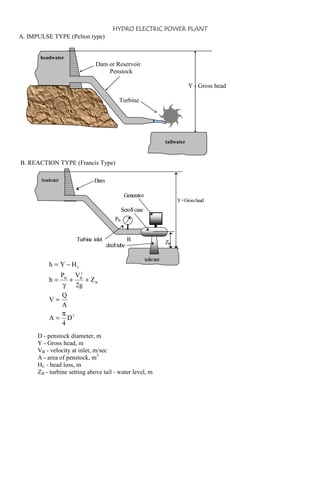
  • 1. HYDRO ELECTRIC POWER PLANT A. IMPULSE TYPE (Pelton type) headwater Dam or Reservoir Penstock Y - Gross head Turbine tailwater B. REACTION TYPE (Francis Type) head water Dam Generator Y =Gross head Scroll case PB Turbine inlet B ZB draft tube h = Y − HL tail ater w 2 PB VB + + ZB γ 2g Q V= A π A = D2 4 h= D - penstock diameter, m Y - Gross head, m VB - velocity at inlet, m/sec A - area of penstock, m2 HL - head loss, m ZB - turbine setting above tail - water level, m
  • 2. PUMP STORAGE HYDRO-ELECTRIC PLANT Upper Pool Motor- Generator Turbine Pum p Lower Pool How turbines work The rotor is the rotating part of a turbine. In a simple turbine, it consists of a disc or wheel mounted on an axle. The axle sits either horizontally or vertically. The wheel has curved blades or buckets around the edges. Nozzles or movable gates called guide vanes aim the fluid at the blades or buckets and adjust its speed. In many turbines, a casing encloses the rotor. The casing holds the fluid against the rotor so that none of the fluid's energy is lost. As a fluid passes through a turbine, it hits or pushes against the blades or buckets and causes the wheel to turn. When the wheel rotates, the axle turns with it. The axle is connected directly or through a series of gears to an electric generator, air compressor, or other machine. Thus, the circular motion of the spinning rotor drives a machine. The rotors of some turbines have only one wheel. However, the rotors of others have as many as 50 or more. Multiple wheels increase the efficiency of turbines, because each wheel extracts additional energy from the moving fluid. In a turbine with more than one wheel, the wheels are mounted on a common axle, one behind the other. A stationary ring of curved blades is attached to the inside of the casing in front of each wheel. These stationary blades direct the flow of the fluid toward the wheels. A wheel and a set of stationary blades is called a stage. Multistage turbines are those that have many stages. Kinds of turbines Turbines are sometimes classified according to their principle of operation. All turbines operate by impulse or reaction, or by a combination of these principles. In an impulse turbine, the force of a fast-moving fluid striking the blades makes the rotor spin. In a reaction turbine, the rotor turns primarily as a result of the weight or pressure of a fluid on the blades. Turbines are more commonly classified by the type of fluid that turns them. According to this method, there are four main kinds of turbines: (1) water turbines, (2) steam turbines, (3) gas turbines, and (4) wind turbines. Water turbines are also called hydraulic turbines. Most water turbines are driven by water from waterfalls or by water that is stored behind dams. The turbines are used primarily to power electric generators at hydroelectric power plants. There are three main kinds of water turbines: (1) the Pelton wheel, (2) the Francis turbine, and (3) the Kaplan turbine. The type of water turbine used at a plant depends on the head available. A head is the distance the water falls before it strikes the turbine. Heads range from about 2.5 meters to more than 300 meters. The Pelton wheel is an impulse turbine. It is used with heads of more than 300 meters. A Pelton's rotor consists of a single wheel mounted on a horizontal axle. The wheel has cup-shaped buckets around its perimeter. Water from a lake or reservoir drops toward the turbine through a long pipe called a penstock. One to six nozzles at the end of the penstock increase the water's velocity and aim the water toward the buckets. The force of these high-speed jets of water against the buckets turns the wheel. The Francis turbine is used when the head is between about 30 meters and 300 meters. A Francis turbine's rotor is enclosed in a casing. Its wheel has as many as 24 curved blades. Its axle is vertical. The wheel of a Francis turbine operates underwater. It is encircled by a ring of guide vanes, which can be opened or closed to control the amount of water flowing past the wheel. The spaces between the vanes act as nozzles to direct the water toward the center of the wheel. The rotor is turned chiefly by the weight or pressure of the flowing water. The Kaplan turbine is used for heads of less than 30 meters. The Kaplan rotor resembles a ship's propeller. It has from three to eight blades on a vertical axle. It works in a manner similar to that of a Francis turbine. Both the Kaplan turbine and the Francis turbine are reaction turbines.
  • 3. FUNDAMENTAL EQUATIONS 1. Total dynamic head or Net effective head a. For an Impulse type h = Y - HL Y - Gross head at plant Gross head - difference in elevation between head water level and tail water level. b. For a Reaction type h = Y − HL 2 PB VB + + ZB γ 2g Q V= A π A = D2 4 h= where: PB - pressure at turbine inlet in KPa VB - velocity of water at penstock, m/sec 2. Discharge or Rate of Flow (Q) Q = AV m3/sec π 2 D 4 where: D - diameter of penstock 3. Water Power (WP) WP = Qγh KW 4. Brake Power (BP) A= 2πTN KW 60,000 where: T - brake torque N-m N - no. of RPM BP = 5. Head loss fLV 2 H = meters L 2gD f - Moody friction factor L - length of penstock 6. Turbine Efficiency (e) e = ehemev e = BP x 100% WP where: eh - hydraulic efficiency em - mechanical efficiency ev - volumetric efficiency 7. Generator Efficiency (ηg) ηg = GP x 100% BP where: GP - electrical output of the generator, KW 8. Rotative Speed (N) N = 120f RPM n where: n - number of generator poles(usually divisible by 4) 9. Turbine Specific Speed N BP Ns = RPM 5 4 3.813(h )
  • 4. 10. Wheel Diameter D= 60φ 2gh meters πN TERMS AND DEFINITION Reservoir - stores the water coming from the upper river or waterfalls. Headwater - the water in the reservoir or upper pool. Spillway - a weir in the reservoir which discharges excess water so that the head of the plant will be maintained. Dam - the concrete structure that encloses the reservoir to impound water. Silt Sluice - a chamber which collects the mud and through which the mud is discharged. Trash Rack - a screen which prevents the leaves, branches and other water contaminants to enter into the penstock. Valve - opens or closes the entrance of the water into the penstock. Surge Chamber - a standpipe connected to the atmosphere and attached to the penstock so that the water will be at atmospheric pressure. Penstock - a channel or a large pipe that conducts the water from the reservoir to the turbine. Turbine - a device or a machine that converts the energy of the water to mechanical energy. Generator - a device or a machine that converts mechanical energy of the turbine into electrical energy. Draft Tube - a pipe that conducts the water from the turbine to the tailrace so that the turbine can be set above the tail water level. Tailrace - is the canal that is used to carry the water away from the plant. Undershot wheel - water enters at the bottom of the wheel tangential to its periphery and impinges on the buckets or vanes. Breast shot wheel - a wheel used for heads up to 16 ft, where water enters between the bottom and top of the wheel at an angle and is prevented from leaving the wheel by a breast wall on the side of the wheel. Over shot wheel - a wheel used for high heads, where water enters the wheel at the top by being discharged from a flume. Gross head - is the difference between the headwater and tail water elevation. Spiral case - it conducts the water around a reaction type turbine.
  • 5. SAMPLE PROBLEMS 1. A pelton type turbine was installed 30 m below the head gate of the penstock. The head loss due to friction is 15% of the given elevation. The length of the penstock is 80 m and the coefficient of friction is 0.00093. Determine a) the diameter of the penstock in mm. (421.6 mm) b) the power output in KW (781.234 KW) 2. What power in KW can be developed by the impulse turbine shown if the turbine efficiency is 85%. Assume that the resistance coefficient f of the penstock is 0.015 and the head loss in the nozzle itself is negligible. What will be the speed of the wheel , assuming ideal conditions where VJET = 2VBUCKET and what torque will be exerted on the turbine shaft. 1670 m elevation L = 6 km ∅1 m ∅3 m 1000 m elevation DJET = 18 cm 3. A hydroelectric plant has a 20 MW generator with an efficiency of 96%. The generator is directly coupled to a vertical Francis type hydraulic turbine having an efficiency of 80%.The total gross head of the turbine is 150 m while the loss of head due to friction at the penstock up to the turbine inlet flange is 4% of gross head. the runaway speed is not to exceed 750 RPM, determine: a) Brake horsepower rating of the turbine (27 927 hp) b) the flow of water through the turbine in cfs (650.53 cfs) c) check if the specific speed falls under that of Francis type turbine. (Ns = 29) d) the rated speed of the turbine (N = 400 RPM) 4. A Francis turbine is installed with a vertical draft tube. The pressure gauge located at the penstock leading to the turbine casing reads 372.6 KPa and velocity of water at inlet is 6 m/sec. The discharge is 2.5 m3/sec. The hydraulic efficiency is 85%, and the overall efficiency is 82%. The top of the draft tube is 1.5 m below the centerline of the spiral casing, while the tailrace level is 2.5 m from the top of the draft tube. There is no velocity of whirl at the top or bottom of the draft tube and leakage losses are negligible. Calculate, a) the net effective head in meters (43.817 m) b) the brake power in kw. (881.2 kw) c) the plant output for a generator efficiency of 92%. (810.7 kw) d) the mechanical efficiency (96.550) 5. A hydroelectric power plant using a Francis type turbine has the following data: Headwater elevation - 190 m Tailwater elevation - 50 m Head loss due to friction - 3.5% of gross head Turbine discharge at full gate opening - 6 m3/sec Turbine – Generator Speed – 600 RPM Turbine efficiency at rated capacity - 90% Turbine is to be direct connected to a 60 hertz a-c generator Determine: a) the brake power in kw (7156.8 kw) b) the number of generator poles (12 poles) c) the electrical power output of the generator if the efficiency is 94% (6727.4 kw) d) the torque developed in N-m (102 925.31 N-m) e) the approximate length of the penstock, if the diameter is 1.5 m and friction factor f is 0.018. (693 m)
  • 6. 6. The flow of a river is 21.25 m3/sec and the head on the site is 30.5 m. It is proposed to developed the maximum capacity at the site with the installation of two turbines, one of which is twice the capacity of the other. The efficiency of both units is assumed to be 85%. Determine: a) Rotative speed of each unit in rpm if the specific of both is 70 rpm. b) Brake power of each unit in kw. c) Number of poles of the generator for 60 cycle current 7. The flow of a river is 21 m3/sec and the head at the power site is 24.4 m (≅80 ft). It is proposed to developed this site with an installation of 3-turbines, 2 similar units and another of half their size, all having the same efficiency of 85%. Find the rotative speed of all these units. (348 rpm; 492 rpm) Ns at 80 ft head = 70 rpm 8. A hydroelectric power plant discharging water at the rate of 0.75 m3/sec and entering the turbine at 0.35 m/sec with a pressure of 275 KPag has a runner of 55 cm internal diameter. Speed is 514 rpm at 260 BHP. The casing is 2 m above the tailwater level. Calculate: a) the net effective head in m (30.039 m) b) the peripheral coefficient (0.61) c) the efficiency (87.8%) 9. A Mindanao province where a mini-hydroelectric plant is to be constructed has an average annual rainfall of 139 cm. The catchment's area is 206 km2 with an available head of 23 m.Only 82% of the rainfall can be collected and 75% of the impounded water is available for power. Hydraulic friction loss is 6%, turbine efficiency is 78% and generator efficiency is 93%. Determine the average kw power that could be generated for continuous operation. POWER = 1.39(206)(1000)2(0.82)(0.75)(9.81)(23)(1-.06)(0.78)(0.93) 8760(3600) = 859 kw 10. A Mindanao province where a hydroelectric power station is to be constructed has an average annual rainfall of 1.93 m. The catchment's area 260 km2 with an available head of 32 m. Only 82% of the rainfall can be collected and 5/8 of the impounded water is available for power.The load factor of the station is 80%, the penstock efficiency is 94%, turbine efficiency 78% and the generator efficiency is 88%. a) Calculate the average power that could be generated b) Calculate the installed capacity of the station c) Assuming no standby unit, give the possible number and size of the units Average power = load factor(peak power) 11. The difference in elevation between the surfaces of water in the storage reservoir and the intake to a turbine was 40.4 m. During a test the pressure head at the later point was 38.6 m and the discharge was1.25 m/sec. The inside diameter of the penstock is762 mm. a) What is the efficiency of the pipeline b) What was the power delivered to the turbine in KW 12. The difference in elevation between the source of the water supply and the centerline at the base of the nozzle of a pelton wheel is 373 m. During a test the pressure at the end of the nozzle was3520 KPa when the flow was 1.3 m3/sec. Inside diameter of the penstock is 762 mm. Compute: a) What power at the base of the nozzle. b) Shaft power developed by the pelton wheel if efficiency is 80%.
  • 7. 13. In a hydroelectric power plant, the water surface on the crest of the dam is at elevation 75.3 m while the water surface just at the outlet of the head gate is at elevation 74.4 m. The head gate has 5 gates of 0.91 m x 0.91 m leading to the penstock and are fully opened. Assume 61% as coefficient of discharge, determine a) The quantity of water that enters the hydraulic turbine in m3/sec b) The KW power that the turbine will developed, assuming 90% efficiency and the turbine is 122 m below the entrance of the penstock c) If all the sides of the gates are sharp, determine the power that the turbine will developed assuming 85% efficiency under the same conditions as b. 75.3 m 0.91 m x 0.91 m 74.4 m 122 m h = (75.3-74.4) + (0.91/2) = 1.355 m v - theoretical velocity just at the outlet of the head gate v = (2gh)1/2 v = 5.156 m/sec Q = 5(0.91 x 0.91)(5.156) = 21.35 m3/sec Q' = 0.61(21.35) = 13.02 m3/sec (actual flow) Fluid Power = Q'(9.81)(1.355+122)(0.90) = 14,183 KW v= 13.02 m/sec 5(0.91 x 0.91) v = 3.14 m/sec (actual velocity at each gate) v2/2g = 0.504 m he = entrance loss he = ke(v2/2g) ke = 0.5 he = 5(0.5)(0.504) = 1.25m (total head loss for 5 gates) H = (1.355 + 122) - 1.25 = 122.105 m Fluid Power = 13.02(9.81)(122.105)(0.85) = 13,257 KW 14. A hydro - storage plant has a 20,000 KW rated capacity, with a utilization factor of 76%. For a 1 1/2 hour peak, determine the hydraulic impoundment in cubic meters of water required with friction factor loss of 6%. Dam elevation at 40 m and hydraulic turbine elevation of 14 m and tailrace at elevation of 7 m. Generator efficiency is 92% and turbine efficiency of 85%, evaporation factor of 20%. If the water is pumped from the lower reservoir with friction factor of 8%, pump efficiency of 76% and motor efficiency of 85%. a) How many KW-hr of power is required to pump the water required to carry the peak b) What is the overall thermal efficiency of the hydro plant. 15. A remote community in the mountain province plans to put up a small hydroelectric plant to service six closely located barangays estimated to consume 52,650,000 KW-hrs per annum. Expected flow of water is 28 m3/sec. The most favorable location for the plant fixes the tail water level at 480 m. The manufacturer of the turbine generator set have indicated the following performance data: Turbine efficiency - 87& Generator Efficiency - 92% Loss in headwork will not exceed 3.8% of the available head In order to pinpoint the most suitable area for the dam, determine a. Headwater elevation b. Type of turbine to be used c. Synchronous speed of generator if number of poles is 6, and frequency is 60 hertz.
  • 8. 16. A proposed hydro electric power plant has the following data: Elevation of normal headwater surface - 194 m Elevation of normal tailwater surface - 60 m Loss of head due to friction - 6.5 m Turbine discharge at full gate opening - 5 m3/sec Turbine efficiency at rated capacity - 90% Turbine is direct connected to a 60 cycle AC generator Required: a. What type of hydraulic turbine would you specify? (Francis) b. Find the Brake Power of the turbine in KW (5628.5 KW) c. Find the number of poles of the generator if Ns = 33 RPM (10 poles) d. Find the KW output of the direct-connected generator if the efficiency is 94% (5,291 KW) 17. The flow of a river of 22 m3/sec produces a total brake power of 5400 KW. It is proposed to install two turbines one of which is twice the capacity of the other. The efficiency and specific speed of both units are assumed to be 85% and 70 RPM, respectively. Determine a. Head in meters (30.5 m) b. Rotative speed of each unit (450 RPM; 320 RPM) c. Number of poles of generator if f = 60 Hz. (16 Poles ; 24 Poles) 18. At a proposed hydro-electric power plant site, the average elevation of the headwater is 600 m, the tailwater elevation is 480 m. Average annual water flow is determined to be equal to that volume flowing through a rectangular channel 4 m wide and0.5 m deep and average velocity of 5.5 m/sec. Assuming that the plant will operate 350 days per year, find the annual energy in KW-HR that the power site can develop if the hydraulic turbine that will be used has an efficiency 80% and generator efficiency of 92%. Consider a headwork loss of 4% of the available head. (76,854,851 KW-hr)
  • 9. ME 413H Final Exam Summer 2005 I A Francis turbine is installed with a vertical draft tube. The pressure gauge located at the penstock leading to the turbine casing reads 372.6 KPa and velocity of water at inlet is 6 m/sec. The discharge is 2.5 m3/sec. The hydraulic efficiency is 85%, and the overall efficiency is 82%. The top of the draft tube is 1.5 m below the centerline of the spiral casing, while the tailrace level is 2.5 m from the top of the draft tube. There is no velocity of whirl at the top or bottom of the draft tube and leakage losses are negligible. Calculate, a) the net effective head in meters b) the brake power in KW c) the plant output for a generator efficiency of 92%. d) the mechanical efficiency II The discharge gauge of a centrifugal pump handling potable water for a class A subdivision reads 175 KPa, while the suction gauge indicates a vacuum of 305 mm Hg. The discharge pressure gauge is 10 m above the pump centerline and the point of attachment of the suction gauge is 3 m below the centerline. The diameters of the suction and discharge pipes are 76 mm and 63.5 mm, respectively. Assuming a head loss of 6 m, and a pump-motor efficiency of 75, Calculate the power required if the flow is 12.5 L/sec of water. (γ = 9.81 KN/m3) ----------------------------------------------ME 413H Final Exam Summer 2005 I A Francis turbine is installed with a vertical draft tube. The pressure gauge located at the penstock leading to the turbine casing reads 372.6 KPa and velocity of water at inlet is 6 m/sec. The discharge is 2.5 m3/sec. The hydraulic efficiency is 85%, and the overall efficiency is 82%. The top of the draft tube is 1.5 m below the centerline of the spiral casing, while the tailrace level is 2.5 m from the top of the draft tube. There is no velocity of whirl at the top or bottom of the draft tube and leakage losses are negligible. Calculate, a) the net effective head in meters b) the brake power in KW c) the plant output for a generator efficiency of 92%. d) the mechanical efficiency II The discharge gauge of a centrifugal pump handling potable water for a class A subdivision reads 175 KPa, while the suction gauge indicates a vacuum of 305 mm Hg. The discharge pressure gauge is 10 m above the pump centerline and the point of attachment of the suction gauge is 3 m below the centerline. The diameters of the suction and discharge pipes are 76 mm and 63.5 mm, respectively. Assuming a head loss of 6 m, and a pump-motor efficiency of 75, Calculate the power required if the flow is 12.5 L/sec of water. (γ = 9.81 KN/m3) ----------------------------------------------ME 413H Final Exam Summer 2005 I A Francis turbine is installed with a vertical draft tube. The pressure gauge located at the penstock leading to the turbine casing reads 372.6 KPa and velocity of water at inlet is 6 m/sec. The discharge is 2.5 m3/sec. The hydraulic efficiency is 85%, and the overall efficiency is 82%. The top of the draft tube is 1.5 m below the centerline of the spiral casing, while the tailrace level is 2.5 m from the top of the draft tube. There is no velocity of whirl at the top or bottom of the draft tube and leakage losses are negligible. Calculate, a) the net effective head in meters b) the brake power in KW c) the plant output for a generator efficiency of 92%. d) the mechanical efficiency II The discharge gauge of a centrifugal pump handling potable water for a class A subdivision reads 175 KPa, while the suction gauge indicates a vacuum of 305 mm Hg. The discharge pressure gauge is 10 m above the pump centerline and the point of attachment of the suction gauge is 3 m below the centerline. The diameters of the suction and discharge pipes are 76 mm and 63.5 mm, respectively. Assuming a head loss of 6 m, and a pump-motor efficiency of 75, Calculate the power required if the flow is 12.5 L/sec of water. (γ = 9.81 KN/m3) -----------------------------------------------
  • 10. ENGR. YURI G. MELLIZA