
Recomendados
Recomendados
Mais conteúdo relacionado
Mais procurados
Mais procurados (20)
Destaque
Destaque (20)
Semelhante a V46 13
Semelhante a V46 13 (20)
Último
Último (20)
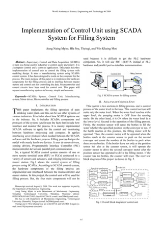
V46 13
- 1. World Academy of Science, Engineering and Technology 46 2008 Implementation of Control Unit using SCADA System for Filling System Aung Naing Myint, Hla Soe, Theingi, and Win Khaing Moe used because it is difficult to get the PLC hardware Abstract—Supervisory Control and Data Acquisition (SCADA) component. So, it will use PIC 16E877A instead of PLC system was being used in industries to control easily and simply. It is hardware and parallel port as interface communication. a computer control and a software application. This paper describes implementation of control unit to control the filling system with modeling design. It aims a manufacturing system using SCADA control system. It has been designed to work on the computer for the process. The main purpose of this paper is to implement the hardware components for the filling process and to interface between master station and control unit for controlling the data. Microcontroller and control circuits have been used for control unit. This paper will support manufacturing systems to be easy, simple and accurate. Keywords—SCADA System, Control Unit, Manufacturing Fig. 1 SCADA system for filling system system, Motor driver, Microcontroller and Filling process. II. ANALYSIS OF CONTROL UNIT I. INTRODUCTION This system is two sections in filling process- one is control T HIS paper implements the filling operation of pure drinking water plant, and this can be use other systems of various industries. It includes about how SCADA systems use process of the water level in the tank. This control section will make only the water level. When the water level reaches at the upper level, the pumping motor is OFF from the running in the industry. So, it includes SCADA components and mode. On the other hand, it is ON when the water level is at protocols of the system. And it uses the facts that include how the lower level. Second is the operation of the filling process. interface and monitor the process. It is mainly implemented Firstly, the position sensor will sense the bottles to fill the water whether the specified position on the conveyor or not. If SCADA software to apply for the control and monitoring the bottle reaches at this position, the filling motor will be between hardware processing and computer. It applies operated. Then, the counter motor will be operated when the interfacing sever protocol when needed between the SCADA bottles reach at the counter sensor to push on the second software and the hardware process. Filling process designs the conveyor and count the number of the bottles to pack when model with nearly hardware devices. It uses dc motor drivers, there are ten bottles. If the bottles have not only at the position sensing drivers, Programmable Interface Controller (PIC) sensor but also at the counter sensor, it will operate the microcontroller device and parallel port communication. counter motor to drive the second conveyor motor after the So, a typical SCADA control system consists of one or position sensor has operated to drive the filling motor. If the more remote terminal units (RTU or PLCs) connected to a counter has ten bottles, the counter will reset. The overview variety of sensors and actuators, and relaying information to a block diagram of this project is shown in Fig. 2. master station. Fig.1 shows the control system of filling process using SCADA. According to SCADA control system, the hardware components of the filling process are implemented and interfaced between the microcontroller and master station. In this project, the control unit will be used for filling process. But, the four main components will not be Manuscript received August 9, 2008. This work was supported in part by the Department of Mechatronic Engineering. Aung Naing Myint is with Department of Mechatronic Engineering, Mandalay Technological University, Mandalay, Myanmar (phone: 092031474,095-06121995; fax:095-0238618; e-mail: anm2006@gmail.com). Hla Soe is with Department of Mechatronic Engineering, Technological University (Hmawbi), Yangon (e-mail: hs2006@gmail.com). Fig. 2 Overall block diagram of control unit Theingi and U Win Khaing Moe are with DTVE and MSTRD, Yangon (e- mail: most19@myanmar.com.mm). 67
- 2. World Academy of Science, Engineering and Technology 46 2008 III. IMPLEMENTATION OF THE SYSTEM The hardware implementation, design consideration and control circuit will be described. In the complete circuit diagram of the filling process, there will be power supply unit, microcontroller to supervise and control data from the hardware and personal computer, light sensor drive circuit to sense the position of the bottles, filling pump drive circuits to fill the water to the tank and the bottle and conveyor motor drive circuit to operate the conveyor motor. By changing the value of resistors, the output DV voltage can get between 6.2V and 12.4V. But the value of resistors should not less than Fig. 4 Circuit diagram of a comparator 1K. The input DC voltage must be greater or equal 2V than the output DC voltage. And then, these voltages are applied The comparator output switches back to the maximum to the TIP3055 to be stable the output of the motors. negative level and the cycle repeats. The comparator produces The output voltage, Vout = 12.4V a square-wave output. The output amplitude of the square The minimum input voltage is greater than the output wave is set by the output swing of the comparator, and the voltage plus 2.5V. The voltage-follower using LM324 in the resistors R1 and R2 set the amplitude of the triangular output control circuit is used to generate a voltage current which is by establishing the UPT and LPT voltages. Where, the used as a virtual ground for the oscillator. This is necessary to comparator output levels, +Vmax and –Vmaxare equal. In Fig. 5, allow the oscillator to run off a single supply instead of a +/- IRF521 N channel power MOSFET driver is the power voltage dual supply. For triangular-wave oscillator, reference switch. When the driver is ON, it provides a ground path for voltage is half of supply voltage. For the voltage follower, the the motor and when it is OFF the motor’s ground is floating. open loop circuit gain is 1. In this project, when Vref =Vout = 6V, supply voltage is +12V and to get Vref = 6V, Thus, R1 = R2. Therefore, to get Vref = 6V, R1=R2 =100K is chosen for the voltage follower. To operate the PWM circuit requires a steadily running oscillator. Two LM324 op-amps form a square/triangle waveform generator. Triangular-wave oscillator utilizes an op-amp comparator to perform the switching, as shown in Fig. 3. Fig. 5 MOSFET driver for power switching circuit For this MOSFET circuit, supply voltage, VDD = 12V, Vi= + 5.64V, Ri = 1K. The red LED is used simply for convenience, to simulate a DC motor for easy verification of circuit operation. In this project, transistor C945 switching circuit is used to operate the water pump DC motor. When the water level reaches at the upper level, the microcontroller will close Fig. 3 Circuit diagram of triangular-wave oscillator the switch because of the water level control circuit ground is floating. The circuit diagram of pump motor drive circuit is The peak value of the triangular wave is established by the shown in Fig. 6. ratio of resistors R2 by R3 and the saturation voltages. The frequency of both waveforms depends on the R3C time constant as well as the amplitude setting resistors, R1 and R2. It has chosen R3=100K (standard value). A comparator generates the variable pulse width. Pin 6 of the comparator receives a variable voltage from the pulse-width control circuit (potentiometer). In Fig. 4, this compared to the triangular waveform from Pin 14 of the oscillator. By varying the voltage of Pin 6, the on/off points are moved up and down the triangular wave, Fig. 6 Circuit diagram of pump motor drive producing a variable pulse width. The frequency values may be varied to change the behavior of the potentiometer. In Fig. 7, this uses to know the position of the bottles from the microcontroller. The output waveform of the circuit is low 68
- 3. World Academy of Science, Engineering and Technology 46 2008 pulse signal. To generate this waveform, the two switching And, pin 33 and 34 are also used as a filling motor and a transistors are used to get the required input for pump motor because the conditions of rotating and stopping microcontroller. When the bottle reaches in the light of the for the motors is wanted to monitor on the computer. Then, LED, the resistance of the LDR will be taken 1MΩ. the output signals of conveyor motor and pushed motor are sent by pin 35 and 36 to the computer. And then, port D is also used as the input signal pins in this project. Although there are 8-bits in ports, only six pins are used namely from pin 19 to 22 and, pin 27 and 28. These pins are used as upper level sensor, lower level senor, position senor, another position sensor and emergency signal. Pin 28 is also used through the OR gate for a start/stop signal. So, starting and stopping state for process can be made either manual or from computer. Only one pin 8 from port E is used as the emergency output signal. Other pins connections are shown in Fig. 9. Fig. 7 Circuit diagram of position sensor drive There are three probes in water level control system and a buffer CD40106 is used to control the water level. One probe is used as a ground. The other two probes are used as level sensors. These two pins are connected to the +5V supply. In water level control system, only when the water level reaches below the lower sensor probe, the supply will not flow to the ground. At the same time, its supply will flow to the buffer. So, the buffer output will be High state. In this time, the microcontroller will operate the filling motor to fill the water in the tank until the level reach the upper level sensor or the upper level buffer output is Low state. If the water level contact to the upper level senor probe, the supply power will Fig. 9 Pin connection of PIC16F877A flow to the ground. So, the supply of the upper level sensor will not flow to the buffer and its output will be Low state. IV. PROGRAM FLOWCHART FOR THE OPERATION The water level control circuit diagram is shown in Fig. 8. In Fig. 10, When the position sensor 1 get the signal, the conveyor motor will be stopped and the filling motor will be opened. And when the time duration takes 5sec, this motor will be closed and will drive the conveyor motor again. Then, the position sensor 1 and 2 will be checked. If the two sensors get the input signal simultaneously at the same time, after the filling motor has opened, the pushed motor will be operated. And if a limit switch gets a signal, the pushed motor will be stopped. Finally, the number of bottles will count from the PIC. If the counter has complete 10 pieces, the operation will start again. V. EXPERIMENTAL RESULTS IN TEST-BED The experimental results are shown in following. This project is to implement the control unit of SCADA system for Fig. 8 Circuit diagram of water level control filling process. In Fig. 11, the construction of control unit is shown by using the above controller circuits. It showed the The pin connections of the PIC 16F877A are important to overall circuit design with photo. In Fig. 12, the construction control the different parts of the filling process and to work of hardware design for filling process is shown by using the correctly. These connections is described Fig. 9. Pin 2, 3, 4, 5 motors, conveyors and other devices. It used to test the from Port A is used as the counter output pins when the operation of filling process and connect the master station for number of bottles is counted. After the number of bottles had SCADA system. In Fig. 13, the overall control system for counted to ten, the counting will reset. SCADA is shown by photo. This figure is the SCADA control 69
- 4. World Academy of Science, Engineering and Technology 46 2008 system for filling process. It connected with master station using personal computer to monitor the filling process. So, it includes the parallel port communication to interface between master station and control unit. Fig. 12 Photo of overall filling process system Fig. 13 Photo of SCADA system Fig. 10 Program flow chart of the filling process VI. CONCLUSION This paper approached to implement control unit using SCADA system for filling process. It designed control circuits to operate the motors. This motors used for hardware mechanism of filling system. Microcontroller used for the operation of filling process and decision sequences of data. The operation of the system showed with the flowchart of programming. And the result showed with photos of hardware design. This paper designed for the manufacturing system by increasing the control systems. ACKNOWLEDGMENT The author wishes to acknowledge especially to Dr. Theingi for guidance, help and sharing fruitful ideas. The author is deeply grateful to U Win Khaing Moe for willingness to share ideas, experience and presence during presentation. The Fig. 11 Photo of control unit author especially wishes to acknowledge his teachers at Department of Electronic Engineering and Information Technology and Department of Mechatronic Engineering for their encouragement, help, support and guidance during the 70
- 5. World Academy of Science, Engineering and Technology 46 2008 theoretical study and thesis preparation duration. The author is [26] Prof. James Trevelyan, “SCADA System Development – Design Study”, Dept of Mechanical & Mat. Engineering, the University of Western much obliged to Dr. Hla Soe, for his effective suggestions and Australia, June 2000. sharing their valuable experience. REFERENCES Aung Naing Myint was born at Myaungmya, Myanmar in [1] Ronald L. Krutz, Securing SCADA Systems, by Wiley Publishing, Inc., 1977 and is a lecturer from Department of Mechatronic Indianapolis, Indiana, 2006 . Engineering, Mandalay Technological University, [2] Michael P. Ward, An Architectural Framework For Describing Mandalay, Myanmar. The author has got Degrees as Supervisory Control And Data Acquisition (SCADA) Systems, by Bachelor of Engineering (B.E), Master of Engineering Publishing Monterey, California, September 2004. (M.E) with title “Design and Construction of power storage [3] IDC Technologies, “The IDC Engineers Pocket Guide”, Fourth Edition, banks for Solar Power System” and Doctor of Philosophy Australia, 2003. Available: http:// www.idc-online.com (Ph.D) with the title “Design and Application of SCADA [4] Thomas E. Kissell, Industrial Electronics, Prentice Hall International Based Control System for Filling Process (Interfacing and Monitoring)”. The Editions, by Prentice- Hall, Inc, 1997. author’s main field is Mechatronic subject and researched in the Mechatronic [5] Curtis D. Johnson, Process Control and Instrumentation Technology, field as control system, industrial manufacturing, SCADA control system, Seventh Edition, by Pearson Education, Inc, 2003. DCS system, programming, PIC Microcontroller, robot control, and PLC. The [6] Mustafa A. Mustafa, Microcomputer Interfacing and Application, author published with the title “Design and Application of SCADA Based second edition, Newnes, Jordan Hill, Oxford OX2 8DP, 1994. Control System for Filling Process (Interfacing and Monitoring)”,The Journal [7] Jan Axelson, “Parallel Port Complete”, PO Box 16262, Irvine, CA of Ministry of Science and Technology, Myanmar, Vol.1,No.1.June, 2008 and 2713, 1994. Available: http://www.Ivr.com “Real-Time Monitoring of SCADA Based Control System for Filling [8] Gareth Talamini, Operator Interface Design for Industrial Control, Process”, International Conference on Power Control And Optimization University of Queensland, St Lucia, Qld 4072, October 1997. PCO2008, Chiangmai, Thailand, July 2008 by advisor. [9] Douglas V.Hall, Microprocessor and Interfacing Programming and Hardware, second edition, Macmillan/McGraw-Hill School, US, 1992. Dr. Hla Soe is is a lecturer from Department of Mechatronic Engineering, [10] Gary Cornell and Jonathan Morrison, Programming VB.NET: A Guide Technological University (Hmawbi), Yangon, Myanmar. for Experienced Programmers, Copyright © United States of America, 2002. Dr. Theingi is a Deputy Director General from Department of Technical and [11] Jose Angel Gomez Gomez, “Survey of SCADA Systems and Vocational Education, Ministry of Science and Technology, Yangon, Visualization of a real life process”, S-581 83 Link’oping, Sweden, June Myanmar. 2000. Available: http://www.ep.liu.se/exjobb/isy/2002/246 [12] Kepware Technologies,“User Configurable Driver Users Manual”, U Win Khaing Moe is a Deputy Director General, Myanmar Scientific and P.O.Box 140524, Austin, 2002. Available: http://www.Kepware.com Technological Research Department, Ministry of Science and Technology, [13] Lukas Tan, “Mobile SCADA with Thin Clients”, Department of Yangon, Myanmar. Engineering, FEIT, Australian National University, 1991. Available: http://www.abpubs.demon.co.uk/scadasites.htm [14] Dave Grundgeiger, Programming Visual Basic .NET, First Edition, Publisher: O'Reilly & Associates, Inc., 1005 Gravenstein Highway North Sebastopol, CA 95472, January 2002. Available: http://www.oreilly.com/catalog/progvbdotnet [15] G.W.Juette and Ramakant A. Gayakwad, OP-Amps and Linear Integrated Circuits, Third Edition, USA, 1985. [16] Arpad Barna, Operational Amplifiers, Printed by Joho Wiley and Sons Inc, United States of America, 1971. [17] Thomas L. Floyd, Electronic Devices Volume 2, Fourth Edition, Printed by Prentice-Hall Inc, A Simon and Schuster Company, New Jersey, 1996. [18] Microchip Technology, “PIC 16F87X DATA sheet 28/40-pin 8-bit CMOS FLASH Microcontrollers”, in USA, 2001. Available: http://www.microcontroller.com/catalog/database [19] Gareth Talamini, Operator Interface Design for Industrial Control, Submitted for the degree of Bachelor of Engineering (Honours) In the division of Electrical and Electronic Engineering, October 2004. [20] Lead Automation Analyst and Information Technology specialist, “Private Conversation at a major oil company drilling Facility”, Bakersfield, CA, 22 April 2004. [21] Tomas E. Dg –Liacco, “Modern Control Centre and Computer Networking,” IEEE Computer Applications in power, Vol.7. Issues 4,PP.17-22, October 1994. [22] Integrated Circuits, “Data Sheet”, 74HC/HCT 157, Quad 2-input Multiplexer, December 1990. [23] Hla Soe, “Design and Application of SCADA Based Control System for Filling Process (Hardware Implementation)”, MTU, Mandalay, Myanmar, November 2007. [24] Aung Naing Myint, “Design and Application of SCADA Based Control System for Filling Process (Interfacing and Monitoring)”, MTU, Mandalay, Myanmar, November 2007. [25] Lukas Tan, “Mobile SCADA with Thin Clients”, Department of Engineering, FEIT, Australian National University, 1991. Available: http://www.abpubs.demon.co.uk/scadasites.htm 71