1. CIRCUIT
IDEAS
AUTOMATIC PHASE CHANGER S.C. DW
IVEDI
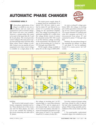
MUHAMMAD AJMAL P. The mains power supply phase R
is stepped down by transformer X1 to
I
n three-phase applications, if low deliver 12V, 300 mA, which is recti- As soon as phase-R voltage goes
voltage is available in any one or fied by diode D1 and filtered by ca- below 200V, the voltage at inverting
two phases, and you want your pacitor C1 to produce the operating pin 2 of IC1 goes below reference volt-
equipment to work on normal voltage, voltage for the operational amplifier age of 5.1V, and its output goes low.
this circuit will solve your problem. (IC1). The voltage at inverting pin 2 of As a result, transistor T1 conducts and
However, a proper-rating fuse needs oprational amplifier IC1 is taken from relay RL1 energises and load L1 is
to be used in the input lines (R, Y and the voltage divider circuit of resistor disconnected from phase ‘R’ and
B) of each phase. The circuit provides R1 and preset resistor VR1. VR1 is used connected to phase ‘Y’ through relay
correct voltage in the same power sup- to set the reference voltage according RL2.
ply lines through relays from the other to the requirement. The reference volt- Similarly, the auto phase-change of
phase where correct voltage is avail- age at non-inverting pin 3 is fixed to the remaining two phases, viz, phase
able. Using it you can operate all your 5.1V through zener diode ZD1. ‘Y’ and phase ‘B,’ can be explained.
equipment even when correct voltage Till the supply voltage available in Switch S1 is mains power ‘on’/’off’
is available on a single phase in the phase R is in the range of 200V-230V, switch.
building. the voltage at inverting pin 2 of IC1 Use relay contacts of proper rating
The circuit is built around a trans- remains high, i.e., more than reference and fuses should be able to take-on
former, comparator, transistor and re- voltage of 5.1V, and its output pin 6 the load when transferred from other
lay. Three identical sets of this circuit, also remains high. As a result, transis- phases. While wiring, assembly and in-
one each for three phases, are used. tor T1 does not conduct, relay RL1 re- stallation of the circuit, make sure that
Let us now consider the working of mains de-energised and phase ‘R’ sup- you:
the circuit connecting red cable (call it plies power to load L1 via normally- 1. Use good-quality, multi-strand
‘R’ phase). closed (N/C) contact of relay RL1. insulated copper wire suitable for your
WWW.EFYMAG.COM ELECTRONICS FOR YOU • JULY 2007 • 93
2. CIRCUIT
IDEAS
current requirement. nections from mains. 2. If the input voltage is low in two
2. Use good-quality relays with EFY Note: 1. During testing in the phases, loads L1 and L2 may also be
proper contact and current rating. lab, we used a 12V, 200-ohm, single- connected to the third phase. In that
3. Mount the transformer(s) and re- phase changeover relay with 6A cur- situation, a high-rating fuse will be re-
lays on a suitable cabinet. Use a Tag rent rating. Similarly, ampere-rated quired at the input of the third phase
Block (TB) for incoming/outgoing con- fuses were used. which is taking the total load.
94 • JULY 2007 • ELECTRONICS FOR YOU WWW.EFYMAG.COM