EXCITATION SYSTEM.ppt
•Transferir como PPT, PDF•
0 gostou•858 visualizações

This document discusses automatic voltage regulators (AVRs) and excitation systems for synchronous generators. It provides information on: 1) The basic concepts of excitation systems including synchronous generator operating zones, synchronous condenser and motor zones, and stability requirements. 2) The response characteristics of excitation systems including steady state and transient stability requirements. 3) The components and operation of different excitation system types including DC, AC, brushless, and static excitation systems. 4) The components, controls, and protection features of AVRs including voltage regulators, current regulators, set point controls, and under/over excitation limiters.

Recomendados
Mais conteúdo relacionado
Mais procurados
Mais procurados (20)
Semelhante a EXCITATION SYSTEM.ppt
Semelhante a EXCITATION SYSTEM.ppt (20)
Mais de vishal laddha
Mais de vishal laddha (20)
Último
Último (20)
EXCITATION SYSTEM.ppt
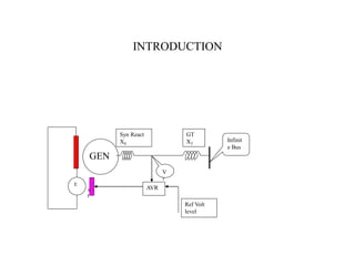
- 1. INTRODUCTION Syn React XS GT XT Infinit e Bus V T AVR Ref Volt level E x t GEN
- 2. BASIC CONCEPT +R -R +X -X Syn Gen over-Excited zone Syn Gen under-Excited zone / Ind. Gen No Excitation (FB open) Syn Condencer Over-excited zone Syn Motor under-Excited
- 3. OPERATIONAL REQUIREMENT * FAST & HIGH RESPONSE * HIGH DEGREE OF RELIABILITY * STABLE ARREANGEMENT OF FIELD DISCHARGE
- 4. RESPONSE CHARECTERISTICS P 0 180° 90° Pmax UNSTABLE ZONE STABLE ZONE P= E x V X Sin 1 2 P1 P2 INCREASED EXCITATION I V Infinite Bus Voltage E 1 1 I at Unity PF 2 2 E I E Lag Load STEADY STATE I.Xe 1 pu 0.9 pu TIME Rise Time SETTLING TIME OVER SHOOT Steady State Error < 0.5% Ideal Performance One Over shoot & One Under Shoot TRANSIENT STABILITY Severe disturbance during FAULT for a short time dip in the M/C terminal voltage & power transfer –resulting acceleration of m/c. Response Characteristics Time 0.5Sec Rated Ceiling DYNAMIC STABILITY Following a disturbance , the group of m/c operating in the sane control group Experience smaller oscillation reacting with each other , Hence change of Excitation May not result in a stable operation for a slow acting exciter having a inherent time delay Depending on the oscillation a separate excitation requirement to be meet. Faste excitation System meet this requirement rather avoid this problem to certain extent by PSS to damp out The smaller oscillation
- 5. CAPABILITY & LIMITATION 1pu 247MW 220 MW 210MW 118 100 LEADING LAGGING 130 δ Φ Stator Current Limiter Field Current Limiter Turbine Limit 70MW β γ Under Excitation Limiter (Auto) Under Excitation Limiter (Man)
- 6. Type of Excitation System * DC EXCITATION SYSTEM : Using DC Exciter & Voltage Regulator * AC EXCITATION SYSTEN: Using AC exciter, static rectifier & volt. regulator * BRUSHLESS EXCITATION SYSTEM: AC exciter, rotating diode & volt. regulator * SEE : static excitation system without any rotating machine, Thyristor used for Controlled DC of main generator
- 7. COVENTIONAL DC EXCITER DC Exciter GEN FDR FB FF FB Additional Fld Wndg Controller 3 ph AC Mag Ampl Gen Volt Feedback From Pilot Exciter DC Exciter Shunt Fld Amplidyne Buck Fld Boost Fld Fig-1A Fig-1B
- 8. INDIRECT HIGH FREQ. AC EXCITER WITH BRUSH & WITHOUT BRUSH AC Exciter FDR FB FF PMG GEN AC Exciter Rotating Diode With Brush Without Brush GEN
- 9. BASIC DIA. OF BRUSHLESS EXCITATION SYSTEM 10 no 10 no 10 no GEN 2080A 235V AVR (AUTOMATIC VOLTAGE REGULATOR) PMG MAIN EXCITER 3200A 420V 150Hz 220V 400Hz +ve Wheel -ve Wheel CT PT FDR FB For Rotor E/F Q a x i s Generator Control Desk ON/OFF & STATUS GRP(L/O) & ATRS (speed> & < 2790 rpm Q-Axis Coil mv 6 50A 1sec,15KWS
- 10. BASIC DIA. OF STATIC EXCITATION SYSTEM CT PT Excitation Transformer Aux Tr + _ FB FF 3 ph 415v ac 1 Shunt Amp Extn Tr. O/C Prot CT 2. 5MVA FDR R 220v DC Gen. Control Desk AVR (AUTOMATI VOLTAGE REGULATOR) Shunt ON/OFF & STATUS 575 volt Six Pulse
- 11. BLOCK DIA. AVR (BRUSHLESS) SET POINT GEN VOLT (AUTO) PSS V/Hz LIMITER ACTUAL GEN VOLT REACTIVE POWER > ACTIVE POWER > UNDER-EXCITATION LIMITER OVER-EXCITATION LIMITER mv V ~ _ ~ _ CT VT1 _ - + - / + + _ + - - + Reactive Power Compensation +/- Volt Reg Current Reg (A) FOLLOW UP CONTROL v(man) v + - EXCITATION BUILD UP & FLD FOCING LIMITATION (Rectifier Limit) Ust (-) FIRING CARD (A) FIELD SUPPRESSION A / M CHANGE OVER GEN –PROT & ATRS FROM GCD AUTO / MAN CHANGEOVER FB ON /OFF & STATUS Ust (A) mv V FIELD AMP FIELD AMP SET POINT EIELD AMP (MAN) - + CURRENT REGULATOR (MAN) _ FIRING CARD (M) Ust (-) Ust (M) M GCD UNDER EXCITATION LIMITER (MAN) RAISE COMMAND & BLOCK LOWER FROM GCD RAISE / LOWER RAISE / LOWER M ~ _ VT3 PULSE BLOCK SYN. VOLT FIRING PULSE
- 12. SET POINT CONTROL COMMAND (AUTO & MAN) AUTO SYN GCD AVR LOWER COMMAND RAISE COMMAND AUTO SYN GCD AVR AVR in AUTO MATCH MATCH AVR in MAN AVR in AUTO GCB is ON MATCH OR OR OR LOWER RAISE AUTO LOWER AUTO RAISE MAN LOWER MAN RAISE OR UNDER EXCT. LIMITER OPTD. DE-Exct(FB OFF) OVER EXCT LIMITER OPTD SET POINT LOWER SET POINT RAISE EXCT. LOW GEN VOLT < REF. MIN. OR OR LOWER FROM FOLLOW UP REF. MAX. RAISE FROM FOLLOW UP RAISE FROM UNDER EXCT (MAN) SET POINT LOWER SET POINT RAISE A U T O M A N OR
- 13. GENERATOR VOLTAGE SET POINT (AUTO & MAN) CONTROL & LOGIC CONTROL & LOGIC SET PT. LOWER (A) FB CLOSE COMMAND 95% VOLT (256 COUNT) SET PT. RAISE (A) SET PT. LOWER (M) SET PT. RAISE (M) UP / DOWN COUNTER 0-1024 for 30Sec D / A CONVERTER UP / DOWN COUNTER 0-1024 for 30 Sec D/A CONVERTER + _ _ + _ _ VOLT REG. (A) CURRENT REG (M) +7.2--+8..8 V (90% --110%) 0—10V (0% --100%) 0—10V (0% ---100%) AUTO MAN 0-+5.7V (0-110%)
- 14. VOLTAGR REGULATOR (AUTO) _ 220K 47K 100K 22M 100K 47K _ RAMP GEN LOW (PERMISSIVE OF FB CLOSE) -10 V 1--RUN UP 0—RUN BACK INV. LIMIT RECT. LIMIT -4 +10 - + - + - + -1 -1 _ _ _ FOLLOW UP INT MAN _ T O C U R R E N T R E G U L A T O R FOLLOW UP INT FEED BACK LIMITER REFERENCE SET POINT DEVIATION MAN +7.2 – +8.8V -8.0V (100%) _ + +10v -10V (>150% of 23A) _ DYN. P. GAIN INT. TIME STATIC GAIN PI O/P 110% (23A) OR GCB OFF FF LIMITED AVR PNL Sel Sw _ RAMP FUNC GENERATOR UP 20Sec DN 5Sec (SPEED > & FB ON) 100 +1.23V 1sec A/M Balance Integrator. O/P 90%…110% Initially OV at RAMP UP it reaches +10 V Ceiling level 46.5A ,135V for 10 sec _ RAMP GEN FAULTY <+0.8V <+5.2V AVR FAULTY A / M C/O (AVR in AUTO & GCB ON +5.5v 33K 33K 100K
- 15. FOLLOW UP INTEGRATOR & MATCHING - - _ _ _ I 23A-5V MAN _ FOLLOW UP INT -10V + 10V _ _ OR BLOCKING OF AUTO FB ON INT >I f INT < I f TO VOLT REGULATOR VOLT INT > I f VOLT INT <I f Ust (AUTO) Ust (MAN) OR FB OFF / DE-EXCT MAN _ _ MATCH AUTO MAN N/O GCB OFF MAN SET VALUE FB OFF OR OR SET PT. NO-LOAD RAISE FROM FOLLOW UP LOW FROM FOLLOW UP SET POINT RAISE (M) SET POINT LOWER (M) -10V +10V _ + _ + MATCH _ _ OR AUTO FB ON F/UP FAULTY DEV + HIGH DEV -- HIGH AUTO MAN DEVIATION A/M Balance _
- 16. CURRENT REGULATOR (AUTO) _ 1.1 X 200% I f (23A) + Fld. Forcing Limiter Faulty (AM) I f (50A) ACTUAL +10V _ -5V (23A) SET POINT FROM VOLT. REG (PI) + _ 33K 33K MATCHING UST AUTO + -15V GCB OFF -0.57V (110% UGN) +15V DE-EXCT (FB OFF) -ve <90 Rectifier -5v32.8 + ve >90 Inverter +5v 148 0 V 90 High Gain +VE for RECTIFIER -VE for INVERTER
- 17. UNDER EXCITATION LIMITER (MAN) IS UTR UST URS _ (+) (-) GEN VOLT (ACTUAL) I Sin (-) Under Excited (+) Over Excited I Cos (+) A B Point- A Point-B Angle- - - - + ve ON RESPONSE. >+0.2V BLOCKING OF SET POINT.(M) LOW >+0.5V RAISE TO MAN SET PT. HIGH - -ve on Response MAN GEN VOLT > 85%
- 18. CURRENT REGULATOR (MAN) 100K - - FB TRIP Gr-1 & -2 -4 +10 -4 +10 - - + + RECT INV +10 (-) GEN VOLT (ACTUAL) GCB OPEN Ust Matching FIRING CKT - +1 -5.5V (110%) +5..3V -2.18V GEN VOLT 106% FROM GEN VOLT SET POINT +5.7 (110%) EXCT. CURRENT (ACTUAL)
- 19. AUTO / MANNUAL CHANGE OVER AUTO CHANNEL MAN CHANNEL By Fault OR By Desire By Desire only Fault: (1) Thyristor Set Auto Faulty (24 MCB OFF,400Hz Power Source OFF, Main Exct Fld Current Low, Conduction Monitor with time delay 100msec) (2) Field forcing Limiter ( 200% Ifn / Ramp Gen at GCB OFF)Faulty Td 0.3 sec. ( Gen Reactive Current >) ( Gen Voltage >)/ (O/P Volt Tyhr.Set >) (3) Auto Channel Power Supply Faulty (400Hz Gate Control MCB ( 24V ,15V MCB) (4) Gen actual Voltage Faulty (PT sensing voltage Faulty) By Desire must be enable through MATCH Push Button Prior to change over Channel to be healthy
- 20. OVER EXCT. LIMITER (FIELD CURRENT) + _ +1 _ +1 IF2N=23A 50A +10V 23A(+6V) -10V -6.3V (105%) -15V -9.49V Gain Gain adjusted so as –10V at 140% +ve MAN +4.58V Integrator Reset on Manual Integrator _ -ve GEN VOLT SET POINT (AUTO) +7.2V (90%) to 8.8V (110%) -10V -1.67V +5V at VGN -10V -8.49V LIMIT VLUE -10V to +5V On Response >0.1V ALARM CLOSE ON AUTO SEL SW V O L T R E G STATOR CURRENT LIMITER BLOCKING SET POINT (RAISE) From Stator Current Limiter SET POINT OF RESPONSE - Response Time 10Sec Res. Time 30s 20s 10s 1.4 1.2 FLD CURRENT Setting Integrator RESET
- 21. OVER EXCT. LIMITER (STATOR CURRENT) _ Stator Current +VE +6V (9054A) GAIN +15V Gain adjusted 140% Ign=-10V -10V -6.3V (105%) - - +1 - -6V (247MVAR) Over Excitation >130MVAR +5V At Vgn -10V -9V LIMITE VALUE Resp. Time +10…-10V 10sec _ ALARM STATOR CURRENT HIGH PERMISSION FOR STATOR CURRENT LIMITER V O L T R E G CLOSE ON AUTO SEL SW FROM ROTOR CURRENT LIMITER LED IND REACTIVE CURRENT HIGH Td 750ms
- 22. UNDER EXCITATION LIMITER Characteristics (AUTO) B D _ -1 _ +1 _ GEN VOLT (-8V dc) +2.88V (118MVAR) VBR ~ IY ~ MVAR + Lag - Lead MW 6V (247MVAR)) + 6V (247MW) - 10V VY-R VY-B IY -5.31V (218MW) _ -6.0V (247MW) -2.43V (100MVAR) A -ve on Response +ve on Response A B C D 100MVAR 0 118MVAR LEAD LAG 70MW 218MW -1.71V (70MW)
- 23. UNDER EXCITATION LIMITER Dynamic Performance (AUTO) 1K 475K -1 _ +1 _ +1 _ + _ +10V _ _ + VE BLOCKING GEN VOLT < 85% +VE ON RESPONSE GEN VOLT REF. +7.2V ---+8.8V +10V +5V + -VE ON RESPONSE -VE ON RESPONSE _ ALARM OF RESPONSE >2V INTEGRATOR PROPORTIONAL SEL SW SEL SW VOLT REG V O L T R E G Min. to Respond (-0.7V) LIMITER OF FAST CORRECTING ACTION OF PROP. AMPLIFIER 1F AUTO AUTO P Gain Match with exciter Time Const. INTEGRATOR RESET Gen Volt > 90%
- 24. V/Hz LIMITER (AUTO) AUTO GEN VOLT >0.5 pu +10V INTEGRATOR VOLT REG SEL SW -1 _ +1 _ _ V/Hz HIGH ALARM GEN VOLT VYB GEN VOLT VY-N ˜ +8V =50Hz V f -7.2 to –8.0V 1 pu to 1.1 pu -7.44V (1.07 pu) V VG + ve to –ve ON RESPONSE -ve to +ve ON ACTION V/Hz TIME 1.2 18sec 1.3 10sec _ Response Value (Setting) Setting V /Hz ( p.u.) Res. Time 10s 20s 30s 1.2 1.3
- 25. REACTIVE POWER COMPENSATION (AUTO) VOLTAGE REGULATOR +/-6V 247MVAR Control the Generator voltage to partly compensate for the voltage drop due to Unit Transformer or voltage rise due to long Transmission line charging on Generator voltage build up specially for Hydro set Effect of this reactive current adjustable between 0..0.1% of rated voltage AVR of the large generators are preferably operated without compensation
- 26. POWER SYSTEM STABILISER (AUTO) PART-1 _ + + + + F U X _ + V P (Change of Power) V F (Change of Freq. i.e. Slip Signal) U I SIGNAL CONVERTER ACTIVE POWER SIGNAL CONVERTER 3Volt for 1pu of Voltage & Current Signal 0.61Vac 210MW +5.5V 0..-10V 0V for P> Pmin (60%) Power Monitor >60% VOLTAGE MONITOR >90% <110% ACCELARATING SIGNAL 2V / HZ < > 50HZ 0V at 50HZ SENSING OF ROTOR SIGNAL V-I.Xq (Xq=1.89) -10..+10V -10…+10V Tc=10sec Tc=10sec 0 0 0 0
- 27. POWER SYSTEM STABILISER (AUTO) PART-2 K+ K+ K- For FAULT P/ t >0.15pu / 100 msec C 5..10% Diff. PROPORTION REGULATOR X X MONITORING (BLOCKING) +1.6V -1.6V STAB. SIGNAL EXCCED LIMIT >20 SEC ACTIVE POWER < 60% (BLOCK) VOLTAGE >90% <110% (BLOCK) P F SUMMING & MONITORING STABILISING SIGNALADAPTER Kp PROP. WT. With Z.Diode (Kp+C) (I/P)² Gain Km at NETWARK FAULT Weighted P Weighted F Weighting of Stab. Signal during Power Swing have a square characteristics i.e. for small swing influence of Slip Stab. be very week & for large swing influence of Slip Stab be very strong. V . R E G Sel Sw AUTO & PSS ON ** ** Mixing Resistor determine the weighting of Stab Signal w.r.t. Signal of Voltage Regulator 10k820K (#1,2)/ 560K(#3) done during tuning of PSS through Step Test S/H Peak value Detector _ C Km LIMITATION
- 28. FIRING CARDS (AUTO) R S T 220V 400HZ From PMG 30V 400HZ R S T + 9V 0 ZERO CROSSING DETECTOR L O G I C (DOUBLE PULSE) 180- / 20 6 PULSE 5.6V 0=90° At Ust =0V W (MAX ANGLE) INVERTER LIMIT G (MIN ANGLE) RECTIFIER LIMIT Ust DOUBLE PULSE BLOCKING 1 BLOCK ;0 ENABLE PULSE FINAL STAGE AMPLIFIER 0 ENABLE 1 (N/C) BLOCKING M BLOCKING AT "MAN” BY SELECTION MONITOR “M” POTENTIAL HEALTHYNESS 0 BLOCKING 1 (N/C) ENABLE BLOCKING AT RUNBACK MODE (GCB OFF & SPEED <) OR FB TRIP ON PROT. OPTD. EXCT. BLOCKED AT AVR PANEL SWITH OFF POWER ISOLATOR THY(AUTO ONLY) AUTO NOT SELECTED b6 d28 z28 d24 0BLOCKING 1(N/C)ENABLE R+ R- S+ S- T+ T- + + + _ A32 M75 148 9V 0 9V 0
- 29. FIELD BREAKER CONTROL DURING START-UP & SHUTDOWN 500 CC OR AUTO & RAMP MIN AUTO SET MIN AUTO CH. HEALTHY MAN & SET MIN MAN CH. HEALTHY PERMISSION FB ON FB ON COMMAND FB TRIP VOLT (220V) HEALTHY EXCT NOT BLOCKED FROM AVR PANEL FB ON COMMAND FROM ATRS / GCD OR OR GEN PROT. CL-A or B Group-1 GEN PROT. CL-A or B Group-2 OR OR GCB OPEN & SPEED <93% GCB OPEN & FB OFF COMMAND FROM GCD / ATRS EMERGENCY DE-EXCITE FROM AVR PANEL FB OFF COMMAND TC INVERTER OPERATION INVERTER OPERATION FB ON/OFF STATUS FOR RAMP-UP & RUN-BACK
- 30. FIELD BREAKER & FIELD SUPRRESSION FB CLOSING PERMISSIVE : TRIP VOLTAGE HEALTHY & EXCT. NOT BLOCKED FROM AVR PANEL AUTO RAMP GEN MIN & SET POINT MIN. MAN SET POINT MIN. FB CLOSE COMMAND: From GCD OR from ATRS FB OFF COMMAND: From GCD when GCB in OFF condition (Generator Not Loaded) GCB OFF & Speed < Generator Protection Class-A & B ACTION: FB will OPEN through Inverter Operation Pulse Blocking Signal to Gate Control Unit Run_Down of Ramp Function generator UG IF UF t DE-EXCITATION OF UNLOADED GEN BY INVERTER BY INVERTER OPERATION OF THYRISTOR SET GEN VOLT FB FROM AVR TO MAIN EXCITER ROTOR +VE -VE FDR 6, 50A 1Sec,15KWS
- 31. EXCITATION BUILD UP & FIELD FORCING Automatic Voltage Regulator initially calling for maximum excitation (as no feedback), the Thyristor set supplies a higher voltage (upto ceiling level) to the Main Exciter compare to actual requirement under Steady State condition until the actual current reaches the set point coming from Current Regulator. Overdriving the voltage at the Field winding of Main Exciter reduce the Voltage Build Up time. This over driving function referred to below as Field Forcing . IF UF Utmax Itmax Response with Fld Forcing Limitation Response W/O Overdriving function t For Increasing Excitation UG IF UF No-Load (GCB open) For Decreasing Excitation For smaller change / Control , overdrive is achieved by proportional Current Regulator The current & Voltage Limit i.e. (Maximum ) determined by Gate Control Unit
- 32. THYRISTOR & POWER CIRCUIT + _ CONDUCTION MONITORING UNIT FIELD CURRENT >4A THYRISTOR AUTO FAULTY ISOLATOR SWITCH 220V 400Hz 3Phase MCB 0.1..0.16A + _ MAIN EXCITER FIELD 220V 400Hz 3Phase OR THY SET MAN FAULTY R S T R S T R+ S+ T+ R- S- T- R+ S+ T+ R- S- T- MAN CHANNEL AUTO CHANNEL Pulse Transf. 1K 150W R+ S+ T+ R- S- CT
- 33. THYRISTOR POWER CONTROL S-R+ T-S+ R-T+ S- T- R- R-T+ S+ T+ S- R+ T- S+ R- S- S+R- R+T- T+S- T+S- = Firing Angle w.r.t. Natural Commutation <30 =60 T+ T- S+ R- T+ =90 S- R+ =120 0 t S- S-R+ R- RECTIFIER ZONE ZERO VOLT INVERTER ZONE