
Recomendados
Recomendados
Mais conteúdo relacionado
Mais procurados
Mais procurados (20)
Destaque
Destaque (14)
Semelhante a Physical prototyping lab2-analog_digital
Semelhante a Physical prototyping lab2-analog_digital (20)
Último
Último (20)
Physical prototyping lab2-analog_digital
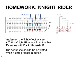
- 1. Implement the light effect as seen in KIT, the Knight Rider car from the 80's TV series with David Hasselhoff. The sequence should be activated when a user presses a button HOMEWORK: KNIGHT RIDER 1
- 2. HOMEWORK: SOLVING IT Besides wiring the breadboard, you had to write the program needed to make it work. The “clever” solution makes use of arrays, we iterate through them using a FOR loop. 2
- 3. PHYSICAL PROTOTYPING © 2011 K3 Creative Commons v3.0 SA-NC Lab 2: Analog & Digital With the Arduino prototyping board
- 4. for(counter=0; counter<end; counter++){} 1)The FOR loop is a software construct that will execute a block of code a number of times. 2)The code will be looped until a certain condition is met 3)FOR loops are constructed with an initialization value, a condition statement, and a counting statement 4)We use them to iterate a certain action a determined amount of times counter initialization FOR LOOP condition counter increment / decrement 4
- 5. ARRAYS 1) ARRAYS are sets of indexed values arranged in order in the processor's memory 2) All the elements in an array have an unique identifier 3) The different “positions” in the array are addressed through numerical index values between squared brackets 4) Array constructors include the type, and the size of the array (the number of elements they consist of) 5) The elements of an empty array are NULL (nothing) 6) It is possible to initialize an array with a specific set of values: E.g. int theList[] = {1, 3, 'e', 19}; 5
- 6. WHAT IS “ANALOG”? The real world is NOT digital. Temperature fluctuation, for example, involves a range of values and generally does not changes abruptly over time. Using analog sensors we measure environmental parameters like temperature, light intensity, etc. These are a set of analog values 6
- 7. Are sensors which transform environmental parameters into a multi-level voltage value (between 0 and 5 volts) There are many types of sensors that provide us with analog voltage values: LDR (or CDS): light dependent resistors aka light sensors NTC and PTC: temperature dependent resistors aka temperature sensors Potentiometers and sliders: angle and position dependent resistors ANALOG SENSORS 7
- 8. READING ANALOG VALUES Microprocessors cannot handle analog values as humans do. They need to be translated into digital data, something the microchip can understand. Sensors transform real world data like the temperature into a voltage value between 0 and 5 volts. These values are different from the HIGH (1) and LOW (0) that characterize digital signals, because they can take any value between 0 and 5 volts. E.g: 0.3 volts, 3.27 volts, 4.99 volts are possible values. The readings resolution depends on the capabilities of the processor/microcontroller you are using. Arduino can distinguish 1024 different levels between 0 and 5 volts. 8
- 9. Are devices which change resistance (and thus the voltage) when you twist or slide them. Arduino can measure the voltage which flows through them. We can use this data to control other things, like LED’s. We call potentiometer those that rotate around one of their axis We call sliders those that move linearly along one of their axis POTENTIOMETERS vs SLIDERS A circuit using a potentiometer A circuit using a slider 9
- 10. CONNECTING THE POTENTIOMETER Potentiometers are useful for improvising quick interfaces. The recommended resistive value is 10 Kilo Ohms. (10K) On the Arduino board there are 6 Analog Input pins, they are numbered from 0 to 5. Analog inputs are not declared in the setup of the programs, unlike the Digital Inputs. We will use this easy circuit to control the oscillation speed of the basic Blink-LED example 10
- 11. analogRead(pin number); Returns the value from a specific analog port Values from 0 to 1023 0v = 0 5v = 1023 READING THE SENSOR 11
- 12. int potPin = 2; // select the input pin for the potentiometer int ledPin = 13; // select the pin for the LED int val = 0; // variable to store the value coming from the // sensor void setup() { pinMode(ledPin, OUTPUT); // declare the ledPin as an OUTPUT } void loop() { val = analogRead(potPin); // read the value from the sensor digitalWrite(ledPin, HIGH); // turn the ledPin on delay(val); // stop the program for some time digitalWrite(ledPin, LOW); // turn the ledPin off delay(val); // stop the program for some time } EXAMPLES ► ANALOG ► ANALOG INPUT
- 13. LDR Light dependent resistor We call the resistor a “pull up” resistor It is usually 10K You can use exactly the same code as in the previous example 13
- 14. FADING LEDS 1) LEDs are Light Emmitting Diodes, and can only be turned on or off. 2) However, it is possible to fake their level of intensity through the use of a mathematical trick called PWM (Pulse Width Modulation) which will be explained later. 3) In essence, what you need to know for making the next experiment, is that there is a function called analogWrite(pin, intensity) that will write an analog value to one of the PWM- labelled pins on your prototyping boards. 4) PWM runs in parallel to the rest of Arduino, which means it will not stop any of the other processes which are running. 5) Hook up one LED with it's correspondent resistor to e.g. pin 10, and execute the following example. 14
- 15. EXAMPLES ► ANALOG ► FADING LED int value = 0; // variable to keep the actual value int ledpin = 9; // light connected to digital pin 9 void setup() { // nothing for setup } void loop() { for(value = 0; value <= 255; value+=5) // fade in (from min to max) { analogWrite(ledpin, value); delay(30); // waits for 30 milliseconds } for(value = 255; value >=0; value-=5) // fade out (from max to min) { analogWrite(ledpin, value); delay(30); } }
- 16. SERIAL COMMUNICATION USING THE SERIAL LIBRARY Serial.xxxx Serial defines a method to use the serial port Serial.begin(baud); Placed in setup to initiate serial communication ”baud” is baudrate (”communication-speed”) Serial.print(); Writes (sends) something to the serial port Serial.println(); Writes (sends) with cr and lf 16
- 17. PROGRAMMING SUMMARY Commonly used Arduino methods: int analogRead(pin); reads an analog value from an analog pin number analogWrite(pin, value); writes a time-dependant signal through the use of the so-called PWM pins Serial.println(data); sends data back to the computer to be seen through the serial monitor Serial.begin(baud); opens the serial communication at baud speed 17
Notas do Editor
- Encourage people to interrupt you so you can help them immediately. Explain they do you a favor. It’s good to time the duration of the presentation.
- Explain the three parameters.
- Again use the cooky jar analogy. Explain the importance of positions. Position 0 is the first position in the array. Instead of 1. Find an explanatory picture
- The real world has a range of values between 0 and 1. Arduino does not understand ranges of values. The analog pins are used to transform values between a resistance measurement between 0 and 5 volts, chopped up in a range of 1024 values.
- LDR means Light Dependent Resistor. Resistor which changes value based on the amount of light. NTC, temperature sensor, gives value between 0 and 1024 based on temperature. NTC means Negative Temperature Coefficient resistor, NTC’s are also called Thermistors. Potentiometers and sliders. These are commonly used in equalizers, and hi-fi sets and other consumer electronics. Explain potentiometer. It used 3 pins, An analog pin, power and ground. You actually measure the resistance through the potentiometer to the ground. Always connect the middle pin on the potentiometer to an analog pin first, because if you mix the pins up then it burns out! The power and ground pins don’t matter which way around you connect them, only the values will be inverted. Explain analogRead. When it reads 0 it means there is 0 volts going through the potentiometer, if it shows 1023 then 5 volts is going through it.
- Finns det tid så kombinera med knight ridern!
- Do a livecoding session showing the analog input session
- Explain how you can make an LED burn at half brightness by quickly turning it on and off. Water analogy: Turning on and off a water tap to make a steady flow. PWM pins: 3,5,6,10,11 identifiable the tilde ~ sign. Now finally Windows users can have that nice fading LED effect when they charge their computer. ;) Let’s do live coding here also, the fading LED example
- Next time: Serial communication. Serial communication is a library so we can call it when we need it. You don’t always need it so you can save space by leaving it out. Use println to print out data on a new line. Otherwise it lines up and becomes illegible. What we explained now is 90% of all the code you ever need to write. CR = carriage return LF = line feed
- Get some funny examples to show.