SlideShare uma empresa Scribd logo
1 de 78
Baixar para ler offline
Elastimold®
Underground Cable Accessories
Renewable Energy
Power Generation
Transmission and Distribution
At T&B, we’re committed to:
•	 Products which provide solutions to your electrical needs
•	Convenience of single-order, single-shipment
to your site for thousands of stocking items
•	Expert local point of contact for clear, consistent
information regarding training, codes and standards
•	Quality brands that have proven themselves over time
•	Inventive design and manufacture of problem-solving products
•	Offering a best-of-class warranty and returns policy
•	Uniform carton labeling with additional bar-coding
for convenient inventory management
•	Nationwide network of stocking electrical distributors
•	Outstanding customer service capability
•	Supplying you with the right products, convenient
packaging, on-time delivery and competitive pricing
We deliver the solutions that make your job easier and offer the power to bring
it all together in one package. Call us today and let us help you profit from
sourcing your electrical products from the leader, Thomas & Betts.
Choose Thomas & Betts and connect
to the power you need.
For over 100 years, Thomas & Betts has successfully applied innovative
design and manufacturing techniques to meet the changing needs of the
marketplace. Today, we offer more than 100,000 electrical components
and systems to terminate, connect, fasten, protect and identify wires,
components and raceway. Our vast offering makes us one of the largest
and best sources of electrical components in North America.
United States
Tel: 901.252.8000
800.816.7809
Fax: 901.252.1354
Technical Services
Tel: 888.862.3289www.tnb.com
i
T&B Services
Quality You Can Trust
Trust T&B’s dedicated Tool Services Department to answer all questions
regarding tool applications, repair, warranties, sales/lease/rental and technical
information. Ask about our specialized services, including customer/sales training,
demos and calibration/certification of tools.
Tool Services
1-800-284-TOOL
Immediate, Knowledgeable Assistance
Every Thomas & Betts Customer Service Representative is right where the action
is — surrounded by all the support and information they need to answer your
questions and fill your orders faster than ever. Your calls and faxes are automatically
routed to Customer Service Specialists who personally serve your account and can
answer questions about products, order status, price and availability, and other
service-related inquiries.
Phone: 1-800-816-7809
Fax: 1-800-816-7810
Email: generalcustomerserviceteam@tnb.com
Customer Service
1-800-816-7809
Over 170 Years of Industry Experience
Meeting and exceeding our customers’ expectations is a fundamental goal of Thomas
& Betts. Call our Technical Services Department and talk LIVE to an expert who’ll
answer questions and concerns regarding all aspects of our products and services.
Our experienced and knowledgeable staff is second to none in the industry!
Technical Services
1-888-862-3289
i
www.tnb.com
United States
Tel: 901.252.8000
800.816.7809
Fax: 901.252.1354
Technical Services
Tel: 888.862.3289
ii
T&B Online Support
Thousands of Products at Your Fingertips
U.S. contractors and specifiers have made our web catalog their number
one stop. Users can search for technical information by catalog number,
UPC code, competitor number, keyword search, product category and/or
brand. Having found the item(s) they are searching for, they can then use
our Where To Buy function to locate a T&B local distributor and/or other
support services.
Web Catalog
www.tnb.com/webcatalog
T&B Access®
is a global sales tool for our distributor partners, offering:
T&B Access
®
tnbaccess.tnb.com
All of these tools and more are available online 24 hours a day – 7 days a week,
without having to make a single phone call. Multi-lingual options are available in English,
French and Spanish. T&B Access®
now serves over 10,000 satisfied customer users
at over 3,500 locations every month.
•	 Quote Requests
•	 Stock Checks
•	 Pricing Inquiries
•	 Cross Reference
•	 Order Entry
•	 Order Resolution
•	 Shipping Status
•	 Document Look-Up
•	 Automatic Order Receiving
•	 Item History Search
•	 Multiple-Location User Search
•	 Context-Sensitive Help
•	 Shipping Confirmations
•	 Tracking Data
•	Expediting
•	 Returns Processing
•	 Quality Issues
•	 Customer Report Cards
•	 Web Catalog Look-Up
Elastimold
®
Underground
Cable Accessories
In this section...
Elastimold®
Underground Cable Accessories
Overview....................................................................................2–3
200-Amp Loadbreak Elbows.......................................................4–7
200-Amp Deadbreak Elbows......................................................8–9
600-Amp Elbow Connectors................................................... 10-21
600-Amp Separable Cable Joints............................................ 22-23
Multi-Point Junctions.............................................................. 24-25
ComboT Integral Separable Connectors.................................. 26-30
Permanent Distribution Cable Joints....................................... 34-35
Shrink-Fit Cable Joints............................................................ 31-33
Distribution Shrink-Fit Terminations........................................ 36-42
Pre-Molded Terminations..............................................................43
Cable Shield Adapters and Jacket Seals................................. 44-45
Equipment Bushings.....................................................................46
Medium-Voltage Cable Accessories
Technical Information............................................................. 47-52
Shielded Surge Arresters........................................................ 53-59
Transmission Cable Joints...................................................... 60-63
Transmission Cable Terminations........................................... 64-65
Transmission Cable Accessories Installation Tools........................66
Transmission Cable Accessories Technical Information.................67
L-Kits and Vault Stretcher Kits Ordering Information......................68
www.tnb.com
United States
Tel: 901.252.8000
800.816.7809
Fax: 901.252.1354
Technical Services
Tel: 888.862.3289
2
Overview
Power& HighVoltage—Elastimold®
UndergroundCableAccessories
Elastimold®
Separable Connectors, Cable Joints, Cable Terminators
and other cable accessory products have been designed and tested per
applicable portions of IEEE, ANSI and other industry standards including:
•	 IEEE 386™
Standard for Separable Connectors
•	 IEEE 404™
Standard for Cable Joints and Splices
•	 IEEE 48™
Standard for Cable Terminations
•	 IEEE 592™
Standard for Exposed Semiconducting Shields
•	ANSI C119.4 Standard for Copper and Aluminum Conductor
Connectors
•	AEIC CS8 Standards for XLP and EPR Insulated Cables
•	ICEA S-94-649-2004 and S-97-682-2000 Standard for
Cables Rated 5,000 – 46,000 Volts
Cable Joints And Terminations Ratings
Refer to the pages listed below for rating information:
•	PCJ™
Cable Joints, page 32
•	 SFJ Shrink Fit™
Cable Joints, page 29
•	 Cable Terminations, page 34
Separable Connector Ratings
The following chart shows voltage and current ratings which apply to all
Separable Connectors including 200-Amp Loadbreak, 200-Amp Deadbreak
and 600 Series Deadbreak products. The next chart shows switching and
fault close ratings which only apply to 200-Amp Load-Break Connectors.
Application Information:
1.	Load-Break connectors are designed and rated for use on grounded
WYE systems. For application on ungrounded WYE or delta systems,
the next higher voltage class product is recommended. Examples: 5kV
ungrounded: use 15kV class products; 15kV ungrounded: use 25kV
class products; 25kV ungrounded: use 35kV class products.
2.	Products are designed and constructed for all applications including
padmount, subsurface, vault, indoor, outdoor, direct sunlight, direct
buried and continuously submerged in water.
3.	Products are designed and rated for ambient temperatures of -40° C
to +65° C. It is recommended that loadbreak connectors be hotstick
operated at -20° C to +65° C ambient temperature range and at
altitudes not exceeding 6000 feet.
Voltage and Current Ratings
15kV CLASS
RATINGS
25kV CLASS
RATINGS
35kV CLASS
RATINGS
Operating Voltage
Maximum line-to-ground
(See Application Info Note 1)
8.3kV 15.2kV 21.1kV
BIL
Impulse withstand 1.2 x 50
microsecond wave
95kV 125kV 150kV
Withstand Voltage
AC One Minute
DC Fifteen Minute
34kV
53kV
40kV
78kV
50kV
103kV
Corona Extinction Level
@ 3pC Sensitivity 11kV 19kV 26kV
200-Amp Products
Continuous Current: Symmetrical
Momentary Current:
600 Series Products Continuous
Current
Symmetrical Momentary Current:
200 Amp
10kA sym, 10 cycle duration*
600 and 900 Amp
25kA sym, 10 cycle duration*
* Designed for 90° C maximum continuous operating temperature.
Switching and Fault Close Ratings
LOADMAKE/LOADBREAK
SWITCHING FAULT CLOSE
15kV
CLASS
RATINGS
• 1ø and 3ø circuits 8.3kV line
to ground, 14.4kV max. across
open contacts
• 10 loadmake/break operations
at 200 Amps max. with 70 to 80%
lagging power factor
1 fault close operation at 8.3kV
or 14.4kV; 10,000 amps RMS sym;
10 cycles (.17 sec.) 1.3 max. asym
factor applies to new or used mating
parts (up to maximum designated
switching operations)
25kV
CLASS
RATINGS
• 1ø and 3ø circuits 15.2kV line
to ground, 26.3kV max. across
open contacts
• 10 loadmake/break operations
at 200 Amps max. with 70 to 80%
lagging power factor
1 fault close operation at 15.2kV
or 26.3kV; 10,000 amps RMS sym;
10 cycles (.17 sec.) 1.3 max. asym
factor applies to new or used mating
parts (up to maximum designated
switching operations.)
35kV
CLASS
RATINGS
• 1ø and 3ø circuits 21.1kV line
to ground, 36.6kV max. across
open contacts.
• 10 loadmake/break operations
at 200 Amps max. with 70 to 80%
lagging power factor.
1 fault close operation at 21.1kV
or 36.6kV; 10,000 amps RMS sym;
10 cycles (.17 sec.) 1.3 max. asym
factor applies to new or used mating
parts (up to maximum designated
switching operations)
United States
Tel: 901.252.8000
800.816.7809
Fax: 901.252.1354
Technical Services
Tel: 888.862.3289www.tnb.com
3
Power HighVoltage—Elastimold®
UndergroundCableAccessories
Overview
IEEE Standard 386 defines the specific interface dimensions that 200 Amp
and 600 Series elbows, inserts, junctions, equipment bushings and any
mating components must conform to ensure interchangeability. The table below
provides information concerning the types of interfaces supplied by Elastimold®
for various applications and is useful to ensure proper matching of components.
Standard Interfaces for Separable Connectors,
Components and Equipment Bushings
Note: 1. Elastimold®
uses Fig. 7 interface for both 25 and 35kV applications.
BUSHING INTERFACE
VOLTAGE
CLASS
INTERFACE
DESCRIPTION
STANDARD NO.
FIGURE NO.
200-AMP DEEPWELL
EQUIPMENT BUSHING
15kV, 25kV
and 35kV
200-Amp Bushing
Well Interface
8.3kV, 15.2kV and, 21.1kV
IEEE
386-2001
Fig. 3
200-AMP LOADBREAK INSERT 15kV 200-Amp Loadbreak
8.3kV and 8.3kV/14.4kV
IEEE
386-2001
Fig. 5
200-AMP LOADBREAK INSERT 25kV 200-Amp Loadbreak
15.2kV and 15.2kV/26.3kV
IEEE
386-2001
Fig. 7, Note 1
200-AMP LOADBREAK INSERT 35kV 200-Amp Loadbreak
Interface No. 2
21.1kV and 21.1kV/36.3kV
IEEE
386-2001
Fig. 7, Note 1
200-AMP DEADBREAK INSERT 15kV and 25kV 200-Amp Deadbreak
8.3kV and 15.2kV
IEEE
386-2001
Fig. 4
600 SERIES EQUIPMENT BUSHING 15kV and 25kV 600-Amp Deadbreak
Interface No.1
8.3kV and 15.2kV
IEEE
386-2001
Fig.11
600 SERIES EQUIPMENT BUSHING 35kV 600-Amp Deadbreak
Interface No.1
21.1kV
IEEE
386-2001
Fig.13
A
C
D
E
F
G
B
A
C
D
E
F
G
B
www.tnb.com
United States
Tel: 901.252.8000
800.816.7809
Fax: 901.252.1354
Technical Services
Tel: 888.862.3289
4
200-Amp Loadbreak Elbows
Power HighVoltage—Elastimold®
UndergroundCableAccessories
CABLE TO EQUIPMENT
CONNECTIONS
OPERATING ACCESSORIES
BUSHING WELL
PLUG
BUSHING WELL
LOADBREAK
BUSHING INSERT
EXTENDED BUSHING INSERT
LOADBREAK
FEED-THRU INSERT
BOLTED
ELBOW
W/TAP
INSULATED PARKING
BUSHING
GROUNDING
PLUG
PARKING
STAND
FEED THRU
See pages 51-57
for surge arrester
applications
LOADBREAK ELBOW CONNECTOR WITH
OR WITHOUT TEST POINT
SEE CABLE NOTES
SEE CABLE NOTES
SEE CABLE NOTES
GROUNDING
ELBOW
REPAIR
ELBOW
REPLACEMENT
ELBOW
FUSED ELBOW
INSULATED CAP
INSULATED CAP
WITH GROUND
TEST ROD
ASSEMBLY TOOL
200-Amp Loadbreak
Connectors and Accessories
200-Amp Loadbreak Connectors and Accessories provide a
convenient method to connect/disconnect cable and equipment on
power distribution systems. Loadbreak elbows include provisions for
energized operation using standard hotstick tools, allowing loadmake/
break operation and a visible disconnect. Components can be isolated
with insulated caps, plugs and parking bushings.
Optional accessories allow system grounding, testing, bypass, surge
protection and current limiting fusing. Additional connecting points
and taps can be provided by use of junctions or feed-thrus.
Ratings Overview
See page 2 for complete
information, including switching
and fault close ratings.
Current Ratings
200A Continuous
10kA sym. 10 Cycles
Voltage Ratings
15kV Class
8.3kV Phase-to-Ground
14.4kV Phase-to-Phase
95kV BIL
34kV AC Withstand
53kV DC Withstand
11kV Corona Extinction
25kV Class
15.2kV Phase-to-Ground
26.3kV Phase-to-Phase
125kV BIL
40kV AC Withstand
78kV DC Withstand
19kV Corona Extinction
35kV Class
21.1kV Phase-to-Ground
36.6kV Phase-to-Phase
150kV BIL
50kV AC Withstand
103kV DC Withstand
26kV Corona Extinction
200-Amp Loadbreak Separable Connector Components
United States
Tel: 901.252.8000
800.816.7809
Fax: 901.252.1354
Technical Services
Tel: 888.862.3289www.tnb.com
5
Power HighVoltage—Elastimold®
UndergroundCableAccessories
200-Amp Loadbreak Elbows
ILLUSTRATION
(NOT TO SCALE) DESCRIPTION
VOLTAGE
CLASS CAT. NO. NOTES
Grounding Plug
(1/0 AWG x 6'
Ground Lead)
15kV
25kV
161GP
272GP
Grounding
Elbow
(1/0 AWG x 6'
Ground Lead)
15kV
25/35kV
160GLR
370GLR N12
Feed-Thru
15kV
25kV
35kV
35kV
164FT
274FT
371FT
373FT
N6, N18
Feed-Thru
Vertical
15kV
25kV
35kV
164FTV
274FTV
373FTV
Adjustable Bracket
2-Point Feed-Thru
15kV
25kV
35kV
164FT2-AB
274FT2-AB
373FT2-AB
N22
N22
N22
Adjustable Bracket
3-Point Feed-Thru
15kV
25kV
35kV
164FT3-AB
274FT3-AB
373FT3-AB
N22
N22
N22
Adjustable Bracket
4-Point Feed-Thru
15kV
25kV
35kV
164FT4-AB
274FT4-AB
373FT4-AB
N22
N22
N22
Feed-Thru Well 15/25kV
K1601WFT
Feed-Thru Well Vertical 15/25kV
K1601WFTV
Insulated Parking
Bushing
15kV
25kV
35kV
161SOP
272SOP
372SOP
N20
Insulated Parking
Bushing
15kV
25kV
164SOP
274SOP
N22
N22
Test Rod All 200AT
Bushing Well
Plug
15/25kV
35kV
276BWP
M276BWP
Assembly Tool All 370TR N8
ILLUSTRATION
(NOT TO SCALE) DESCRIPTION
VOLTAGE
CLASS CAT. NO. NOTES
Elbow
Connector
15kV
25kV
35kV
165LR-W5X
Use Tables W1 and X1
275LR-W5X
Use Tables W16 and X1
375LR-W5X
Use Tables W3 and X2
N2, 3, 4, 5
N2, 3, 4, 5
N2, 3, 5
Elbow
Connector
w/ Test Point
15kV
25kV
35kV
166LR-W5X
Use Tables W1 and X1
276LR-W5X
Use Tables W16 and X1
376LR-W5X
Use Tables W3 and X2
N2, 3, 4, 5, 23
N2, 3, 4, 5, 23
N2, 3, 5, 23
Jacket Seal
Elbow
Connector
15kV
25kV
165LRJS-W5X
Use Tables W1 and X1
275LRJS-W5X
Use Tables W16 and X1
N2, 19
N2, 19
Jacket Seal
Elbow
Connector
w/ Test Point
15kV
25kV
166LRJS-W5X
Use Tables W1 and X1
276LRJS-W5X
Use Tables W16 and X1
N2, 19, 23
N2, 19, 23
Repair Elbow
Connector
15kV
25kV
167ELR-W5X
Use Tables W5 and X1
273ELR-W5X
Use Tables W5 and X1
N5, 10, 18
N5, 10, 18
Repair Elbow
Connector
w/ Test Point
15kV
25kV
168ELR-W5X
Use Tables W5 and X1
274ELR-W5X
Use Tables W5 and X1
N5, 10, 18, 23
N5, 10, 18, 23
Replacement
Elbow
15kV
25kV
167RLR-W5X
Use Tables W4 and X1
273RLR-W5X
Use Tables W2 and X1
N5, 11, 13
N5, 11, 13
Replacement
Elbow
w/ Test Point
15kV
25kV
168RLR-W5X
Use Tables W4 and X1
274RLR-W5X
Use Tables W2 and X1
N5, 11, 13, 23
N5, 11, 13, 23
Direct Test
Elbow
Connector
15kV
25kV
167DLR-W5X
Use Tables W4 and X1
273DLR-W5X
Use Tables W2 and X1
N2, 5, 21
N2, 5, 21
Direct Test Repair
Elbow
Connector
15kV
25kV
167DELR-W5X
Use Tables W5 and X1
273DELR-W5X
Use Tables W5 and X1
N5, 10, 18, 21
N5, 10, 18, 21
Direct Test
Repair Elbow
Connector
w/Test Point
15kV
25kV
168DELR-W5X
Use Tables W5 and X1
274DELR-W5X
Use Tables W5 and X1
N5, 10, 18,
21, 23
N5, 10, 18,
21, 23
Fused Elbow
(Full Range
Current Limiting)
15kV
25kV
168FLR W0X
274FLR W0X
N23
N23
Bolted Elbow
w/ Tap
15kV
167LRT-W5X
Use Tables W4 and X1
N17
Bushing Insert
15kV
25kV
35kV
35kV
1601A4
2701A4
3701A4
3701A3
N4, 8
N4, 8
N6, 20
20
Extended
Bushing
Insert
15kV
25kV
1601EA4
2701EA4
N8
N8
Feed-Thru
Insert
15kV
25kV
35kV
1602A3R
2702A1
3702A1
N16
N16
N6, 16
Insulated Cap
15kV 160DR N9
Insulated Cap
w/ Ground
15kV
15kV
25kV
35kV
160DRG
167DRG
273DRG
375DRG
N9
N7, 9
N7, 9
N7, 9
Insulated Cap
w/ Ground and
Test Point
15kV
25kV
35kV
168DRG
274DRG
376DRG
N7
N7
N7
Refer to the W and X tables on page 50 for sizing to cable insulation diameter
and conductor size. For cable shield adapters and jacket seals, see page 42.
N1.	Copper lug for use on COPPER CONDUCTOR ONLY.
N2.	W5X indicates that the catalog number includes 02500X long bi-metal compression lug as standard.
For an all-copper lug, replace W5X with W2X in Table X1 to specify the all-copper 02702X lug.
N3.	Also available as housing only. Specify: 165BLR-W; 275BLR-W;
375BLR-W; 166BLR-W; 276BLR-W; 376BLR-W.
N4.	Also available as elbow/insert combination. Specify: 165A4-WX;
275A4-WX; 166A4-WX; 276A4-WX.
N5.	Also available with 200ECS jacket seal included. Add - “S” suffix to catalog number.
N6.	Rated for single-phase applications only.
N7.	Equipped with insulated cuff.
N8.	Includes internal torquing feature using 200AT Assembly Tool.
N9.	Also available without probe. Specify “A” suffix - Example: 273DRGA.
N10.	Repair elbow has extended length contact and elbow housing resulting in a net gain of
31
⁄4 in length.
N11.	Replacement elbow has extended-length contact and elbow housing resulting
in a net gain of 87
⁄8 in length.
N12.	Rated for 25kV thru 35kV applications.
N13.	 Includes long bi-metal contact 00400X.
N14.	160CA Cable Size Adapter can only be used with elbow part numbers 165LR/166LR C size only.
N16.	Fully rotatable for 360° positioning. Includes bail assembly to secure feed-thru insert to bushing well.
N17.	Includes 02800X bi-metal contact.
N18.	Includes 02509X long bi-metal contact.
N19.	Includes built-in jacket seal. Also available as housing only — specify: 165BLRJS-W, 166BLRJS-W,
275BLRJS-W or 276LRJS-W. Also available as elbow/insert combination — specify: 165JSA4-W5X,
166JSA4-W5X, 275JSA4-W5X or 276JSA4-W5X.
N20.	 Includes a black vent ring.
N21.	 Direct Test Connectors, along with a 200TC-X series meter adapter, a properly rated
	 voltage meter and Hot-line Stick provide a means for direct conductor voltage testing.
N22.	 With stainless steel bracket.
N23.	 Test Point Cap catalog number 156-7
N24. Add suffix “-SS” for stainless steel bracket.
www.tnb.com
United States
Tel: 901.252.8000
800.816.7809
Fax: 901.252.1354
Technical Services
Tel: 888.862.3289
6
200-Amp Loadbreak Elbows
Power HighVoltage—Elastimold®
UndergroundCableAccessories
200-Amp Loadbreak Separable Connector Components
CABLE TO CABLE CONNECTIONS
4-POINT
JUNCTION
3-POINT
JUNCTION
2-POINT
JUNCTION
2 POINT WELL
JUNCTION
3-POINT WELL
JUNCTION
4-POINT WELL
JUNCTION
LOADBREAK
BUSHING INSERT
LOADBREAK
BUSHING INSERT
LOADBREAK
BUSHING INSERT
Ratings Overview
See page 2 for complete
information, including switching
and fault close ratings.
Current Ratings
200A Continuous
10kA sym. 10 Cycles
Voltage Ratings
15kV Class
8.3kV Phase-to-Ground
14.4kV Phase-to-Phase
95kV BIL
34kV AC Withstand
53kV DC Withstand
11kV Corona Extinction
25kV Class
15.2kV Phase-to-Ground
26.3kV Phase-to-Phase
125kV BIL
40kV AC Withstand
78kV DC Withstand
19kV Corona Extinction
35kV Class
21.1kV Phase-to-Ground
36.6kV Phase-to-Phase
150kV BIL
50kV AC Withstand
103kV DC Withstand
26kV Corona Extinction
200-Amp Loadbreak Connectors and Accessories (continued)
See pages 51-57
for surge arrester
applications
United States
Tel: 901.252.8000
800.816.7809
Fax: 901.252.1354
Technical Services
Tel: 888.862.3289www.tnb.com
7
Power HighVoltage—Elastimold®
UndergroundCableAccessories
200-Amp Loadbreak Elbows
ILLUSTRATION
(NOT TO SCALE) DESCRIPTION
VOLTAGE
CLASS CAT. NO. NOTES
Contacts:
LR Long Bi-Metal
ELR Bi-Metal
LR Copper
LRT Contact
RLR Contact
All
15/25kV
All
15kV
15/25kV
Use Table X1
02500X
02509X
02702X
02800X
00400X
N1
N2
N3
Elbow Probe
15kV
25kV
35kV
166LRF
274LRF
375LRF
Elbow
Cable Entrance
Insulating Plug
All
10EP-W
Use Table W6
Cable Size
Adapter
15kV
160CA-W
Use Table W6
EB-FA Only
N4
Direct Voltage Test
Meter Adapter for:
HD Electric Meters All
200TC-1 N14
Ross Meters 200TC-2 N14
Chance Meters 200TC-4 N14
2-Way Well
Junction w/
S.S. Bracket
15/25kV K1601WJ2 N6
2-Way Well
Junction w/
“U” Straps
15/25kV K1601WJ2-5 N5, 6, 11
3-Way Well
Junction w/
S.S. Bracket
15/25kV K1601WJ3 N6
3-Way Well
Junction w/
“U” Straps
15/25kV K1601WJ3-5 N5, 6, 12
4-Way Well
Junction w/
S.S. Bracket
15/25kV K1601WJ4 N6
4-Way Well
Junction w/
“U” Straps
15/25kV K1601WJ4-5 N5, 6, 13
2-Point Junction
with/Stainless
Steel Bracket
15kV
25kV
35kV
164J2
274J2
373J2
N7
N7
N7
2-Point Junction
w/“U” Straps
15kV
25kV
35kV
164J2-5
274J2-5
373J2-5
N5, 8
N5, 11
N5, 11
3-Point Junction
with Stainless
Steel Bracket
15kV
25kV
35kV
164J3
274J3
373J3
N7
N7
N7
3-Point Junction
w/“U” Straps
15kV
25kV
35kV
164J3-5
274J3-5
373J3-5
N5, 9
N5, 12
N5, 12
4-Point Junction
with Stainless
Steel Bracket
15kV
25kV
35kV
164J4
274J4
373J4
N7
N7
N7
4-Point Junction
w/“U” Straps
15kV
25kV
35kV
164J4-5
274J4-5
373J4-5
N5, 10
N5, 13
N5, 13
N1.	Repair elbow has extended-length contact and elbow housing
resulting in a net gain of 31
⁄4 in length.
N2.	Copper lug for use on COPPER CONDUCTOR ONLY.
N3.	Replacement elbow has extended-length contact and elbow
housing resulting in a net gain of 87
⁄8 in length.
N4.	160CA Cable Size Adapter can only be used with elbow catalog
numbers 165LR/166LR C, H or CC size only.
N5.	Also available as rubber only, without straps. Specify suffix “-4”
in place of “-5” in the catalog number.
N6.	Supplied with replaceable stud. Replacement stud available
separately. Specify 1000-150.
N7.	Hardware packages, consisting of brackets and straps only,
may be ­ordered separately by specifying “-6” in the catalog number.
Example 164J4-6.
N8.	Hardware package, consists of “U” straps and back plate only,
may be ordered separately by specifying 1601US-J2.
N9.	Hardware package, consists of “U” straps and back plate only,
may be ordered separately by specifying 1601US-J3.
N10.	Hardware package, consists of “U” straps and back plate only,
may be ordered separately by specifying 1601US-J4.
N11.	Hardware package, consists of “U” straps and back plate only,
may be ordered separately by specifying 271-68.
N12.	Hardware package, consists of “U” straps and back plate only,
may be ordered separately by specifying 271-61.
N13.	Hardware package, consists of “U” straps and back plate only,
may be ordered separately by specifying 271-70.
N14.	For use with Direct Test Connectors.
Refer to the W and X tables on page 50 for sizing to cable insulation diameter
and conductor size. For cable shield adapters and jacket seals, see page 42.
www.tnb.com
United States
Tel: 901.252.8000
800.816.7809
Fax: 901.252.1354
Technical Services
Tel: 888.862.3289
8
200-Amp Deadbreak Elbows
Power HighVoltage—Elastimold®
UndergroundCableAccessories
LOCKING AND
REPAIR SPLICE
LOCKING
“Y” SPLICE
FEED THRU
PARKING
STAND
STAND-OFF PLUG
INTEGRAL BUSHING
GROUNDING PLUG
INSULATED PLUG
STRAIGHT PLUG
IN-LINE JUNCTION
TEE SPLICE
BUSHING
WELL
BUSHING
INSERT
BUSHING WELL PLUG
DEADBREAK
FEED-THRU INSERT
3-POINT
JUNCTION
4-POINT
JUNCTION
2-POINT
JUNCTION
CABLE TO EQUIPMENT
OPERATING ACCESSORIES
CABLE TO CABLE CONNECTIONS
200-Amp Deadbreak
Connectors and Accessories
200-Amp Deadbreak Connectors and Accessories provide a quick-
disconnect feature for cable and equipment connections on power
distribution systems.
All deadbreak connectors must be de-­energized before operating and must
be mechanically secured with bails when connected. Components can be
isolated with insulated caps, plugs and parking bushings.
All deadbreak elbows are equipped with test points as standard. Optional
accessories allow system grounding, bypass and lightning surge protection.
Additional connecting points and taps can be provided by use of junctions
or feed-thrus.
Ratings Overview
See page 2 for complete information.
Current Ratings
200A Continuous
10kA sym. 10 Cycles
Voltage Ratings
15kV Class
8.3kV Phase-to-Ground
14.4kV Phase-to-Phase
95kV BIL
34kV AC Withstand
53kV DC Withstand
11kV Corona Extinction
25kV Class
15.2kV Phase-to-Ground
26.3kV Phase-to-Phase
125kV BIL
40kV AC Withstand
78kV DC Withstand
19kV Corona Extinction
200-Amp Deadbreak Separable Connector Components
Except for locking splices all
200A deadbreak products must
be mechanically secured with a
bail when connected
See pages 51-57
for surge arresters applications
INSULATED CAP
STRAIGHT RECEPTACLE
ELBOW
CONNECTOR
United States
Tel: 901.252.8000
800.816.7809
Fax: 901.252.1354
Technical Services
Tel: 888.862.3289www.tnb.com
9
Power HighVoltage—Elastimold®
UndergroundCableAccessories
200-Amp Deadbreak Elbows
ILLUSTRATION
(NOT TO SCALE) DESCRIPTION
VOLTAGE
CLASS CAT. NO. NOTES
Bail 15/25kV 150TB4 N5
Bail 15/25kV 150TB5 N5
Bail 15/25kV 150TB6 N5
Contacts:
Long Bi-Metal
Copper
15/25kV
15/25kV
02500X
02702X
N7
Elbow Cable Entrance
Insulating Plug
15/25kV
10EP-W
Use Table W6
N10
Cable Entrance
Insulating Plug
15/25kV
152EA-W
Use Table W6
N11
Cable Size Adapter 15/25KV
160CA-W
Use Table W6
EB-FA Only
N14
ILLUSTRATION
(NOT TO SCALE) DESCRIPTION
VOLTAGE
CLASS CAT. NO. NOTES
Elbow Connector
w/ Test Point
15/25kV
156LR-W5X
Use Tables W4 and X1
N1, 2
Direct Test
Elbow Connector
15/25kV
156DLR-W5X
Use Tables W4 and X1
N1, 2, 22
Bail Assembly
for 156LR Elbow
15/25kV 150BA
Bushing Insert 15/25kV K1501A1 N3
Feed-Thru Insert 15/25kV K1502A1 N3, 4
Insulated Plug 15/25kV K150DP N3
Insulated Cap 15/25kV K150DR N3
Insulated Parking
Bushing
15/25kV K151SOP N3
Grounding Plug 15/25kV 151GP N3
Feed-Thru 15/25kV K1501FT N3, 6
2-Point Junction 15/25kV K1501J2-U8 N3, 6
3-Point Junction 15/25kV K1501J3-U8 N3, 6
4-Point Junction 15/25kV K1501J4-U8 N3, 6
Elbow Probe 15/25kV 156LRF
Straight
Receptacle
15/25kV
K151SR-W0X
Use Tables W1 and X1
N3, 12,
13, 17, 18
Straight Plug 15/25kV
K151SP-W0X
Use Tables W1 and X1
N3, 12,
13, 19
Tee Splice 15/25kV K150T N3
In-Line Junction 15/25kV K150S N3
Locking Splice/
Repair Splice
15/25kV
K151LS-W0X
Use Tables W1 and X1
N8, 9, 13,
15, 16,
17, 20, 23
Locking “Y”
Splice
15/25kV
K151LY-W0X
Use Tables W1 and X1
N8, 9, 13,
15, 17, 21
Bail 15/25kV 150TB1 N5
Bail 15/25kV 150TB2 N5
Bail 15/25kV 150TB3 N5
N1.	 Includes bail assembly.
N2.	W5X indicates that the catalog number includes a 02500X bi-metal compression lug, which is
rated for either aluminum or copper conductor, as standard. For an all-copper lug, replace W5X
with W2X. Use Table X1 to specify the all-copper 02702X lug.
N3.	Bails are required but not included. Order separately. Consult factory for bails not listed for a
specific application.
N4.	Fully rotatable for 360° positioning. Includes bail assembly to secure feed-thru insert to bushing
well. Elbows bail assemblies are required but not included with the feed-thru insert.
N5.	 Refer to factory for application details.
N6.	 Center-to-center spacing equals 4 inches.
N7.	 Copper lug for copper cable only.
N8.	To order cable legs for different cable sizes, list each leg size “W” and “X”.
Example: K151LY-A1240-A1240-B1220. See Tables W1 and X1 for sizes.
N9.	To order locking contacts for K151LS and K151LY, order 01401X (Al) or 01402X (Cu) for plug
contact. Order 01301X (Al) or 01302X (Cu) for receptacle. See Table X1 for sizes.
N10.	For use with 156LR elbows.
N11.	For use with K151SR, K151SP, K151LS, K151LY receptacles, plugs and splices.
N12.	Also available as housing only. Specify K151BSP-W or K151BSR-W.
N13.	Also available in EB-FA sizes per Table W6 by using 160CA cable adapter with C size plugs
and receptacles.
N14.	 160CA cable adapter can only be used with C size plugs and receptacles.
N15.	Bails are not required for locking splices.
N16.	When used as a repair splice, the assembled length allows 4 for cable­replacement/repair.
N17.	Straight receptacles are also available with test point. Specify K152SR-W0X catalog number.
N18.	W0X indicates that the catalog number includes a 01500X universal aluminum compression lug,
which is rated for either aluminum or copper, as standard. For an all-copper lug, replace W0X with
W2X in Table X1 to specify the all-copper 01502X lug.
N19.	W0X indicates that the catalog number includes a 01600X universal aluminum compression lug,
which is rated for either aluminum or copper, as standard. For an all-copper lug, replace W0X with
W2X in Table X1 to specify the all-copper 01602X lug.
N20.	W0X indicates that the catalog number includes a 01400X universal aluminum compression lug,
which is rated for either aluminum or copper, as standard. For an all-copper lug, replace W0X with
W2X in Table X1 to specify the all-copper 01402X lug.
N21.	W0X indicates that the catalog number includes a 01300X universal aluminum compression lug,
which is rated for either aluminum or copper, as standard. For an all-copper lug, replace W0X with
W2X in Table X1 to specify the all-copper 01302X lug.
N22.	Direct Test Connectors, along with a 200TC-X series meter adapter, a properly rated voltage
meter and Hot-line Stick provides a means for direct conductor voltage testing.
See page 7 for meter adapters.
N23.	 Gains approximately 4 of repair length.
Refer to the W and X tables on page 50 for sizing to cable insulation diameter
and conductor size. For cable shield adapters and jacket seals, see page 42.
www.tnb.com
United States
Tel: 901.252.8000
800.816.7809
Fax: 901.252.1354
Technical Services
Tel: 888.862.3289
10
600-Amp Elbow Connectors
Power HighVoltage—Elastimold®
UndergroundCableAccessories
600 Series deadbreak elbows, straight receptacles, junctions, vault
stretchers and accessories are used to connect equipment and cable
on primary feeder and network circuits. Designs accommodate large
conductors and feature bolted connections and deadfront modular
construction for maximum reliability, performance and versatility.
De-energized connectors can be quickly and easily connected and
disconnected using standard hand tools and equipment in accordance
with accepted operating practices. Optional accessories allow visible
external separation, bypass, isolation, dead-ending, grounding and
testing as well as adding taps, surge arresters and circuit protection.
Hotstick-operable and separable joint systems are shown on
pages 16–19 and 20–21.
Spiking Aid-T
When spiking a medium voltage cable near a stacked T-Body cable
joint, the Elastimold®
Spiking-T is a specially designed product to reduce
outage time and cost. Medium voltage cable is spiked as a means
to assure the circuit is de-energized where there is no sectionalizing
device, direct testing means or provision for grounding. One leg of
stacked T-Body cable joint is spiked/cut with a grounded guillotine type
cable cutter, near the T-Body intersection. Once spiked and proved
de-energized, the cable is re-prepped and a Spiking-T with a lug
extender is assembled and reconnected to the stack. If this stack ever
needs to be spiked again, the Spiking-T provides a convenient place to
spike, no additional cable prep required, just replace the Spiking-T and
the lug extender, reduced outage, reduced cost.
GAD
When your available fault currents exceed 10kA in your underground
systems, the Elastimold®
GAD may be your answer. The Elastimold®
GAD is rated 25kA and installs in the rear interface of a 600 Series
elbow connector (T-Body). The GAD is normally covered and insulated
with an insulating cap that contains capacitive test and a hot stick
operating band. Once the circuit is opened at a disconnecting device,
the test point cap is removed with a hot-stick, and then using an
appropriate capacitive test point meter the test point is checked for
voltage. Then the insulting cap is removed with a hot stick and a high
voltage meter is used to confirm the de-energized state before a ground
cable is connected. No need to remove basic insulating plug, no need
to install temporary grounding adapters, the Elastimold®
GAD is there
when you need it. Also available in a Ball GAD version.
600 Series Deadbreak
Components
United States
Tel: 901.252.8000
800.816.7809
Fax: 901.252.1354
Technical Services
Tel: 888.862.3289www.tnb.com
11
Power HighVoltage—Elastimold®
UndergroundCableAccessories
600-Amp Elbow Connectors
STRAIGHT
RECEPTACLE HOUSING
STRAIGHT RECEPTACLE
STRAIGHT
RECEPTACLE ADAPTER
BOLT 
WASHER
COMPRESSION
LUG
CABLE
ADAPTER
RETAINING
RING
†
†
*†•
SEE PAGES 18–19
SEE PAGES 22–23 FOR
ADDITIONAL JUNCTIONS
SEE PAGES
18–19
HOTSTICK OPERABLE 600 SERIES
CONNECTORS - SEE PAGES 16–19
SEE PAGES 16–17
TEST AND GROUND
CABLE TO EQUIPMENT
ELBOW CONNECTOR
200A TAPS
600 SERIES
TAPS
CABLE TO CABLE
UTILIZING L-KITS
SEE PAGES 14–15
CABLE TO CABLE
(UTILIZING JUNCTIONS)
INTEGRAL
BUSHING
THREADED
STUD BUSHING
EXTENDER
CONNECTING
PLUG
2 PT JUNCTION
3 PT JUNCTION
4 PT JUNCTION
OPERATING
ACCESSORIES
GROUNDING PLUG
INSULATED
PARKING BUSHING
THREADED
COMPRESSION LUG
STICK-OP LOADBREAK
REDUCING TAP PLUG
STICK-OP
CAM-OP
RETAINER
SLEEVES
CAM-OP
LINK CONNECTOR
CAM-OP
CABLE
ADAPTER
COMPRESSION
LUG
VAULT
STRETCHER
THREADED
STUD
VAULT
STRETCHER
CONNECTOR
COMPRESSION
LUG
CABLE
ADAPTER
THREADED
STUD
INSULATED
CAP WITH
TEST POINT
BUSHING
EXTENDER
CABLE
ADAPTER
COMPRESSION
LUG
THREADED
STUD
600 SERIES
ELBOW
INSULATED
PLUG
VOLTAGE
DETECTION
CAP
CONNECTING
PLUG
200A DEADBREAK
SEE PAGES 8–9
200A LOADBREAK
SEE PAGES 4–7
SPANNER WRENCH
DEADBREAK
REDUCING TAP
PLUG
REDUCING
TAP WELL
LOADBREAK
ELBOW TAP
PLUG
CABLE TO CABLE UTILIZING
VAULT STRETCHERS
SEE PAGES 14–15
See pages 51–57
for surge arrester
applications
600 Series Deadbreak
Components
Voltage Ratings
15/25kV Class (5kV thru 28kV)
16.2kV Phase-to-Ground
28kV Phase-to Phase
140kV BIL
45kV AC Withstand
84kV DC Withstand
21.5kV Corona Extinction
35kV Class
21.1kV Phase-to-Ground
36.6kV Phase-to-Phase
150kV BIL
50kV AC Withstand
103kV DC Withstand
26kV Corona Extinction
Note: Elastimold has increased the IEEE
Standard Prod­uction and Design Test levels
for 25kV Class products to include 27kV
and 28kV systems.
* Tested at 8.3/14.9kV
†
Tested at 15.2/26.3kV
• Tested at 21.1/36.6kV
Ratings Overview
See page 2 for complete information.
Current Ratings
(Prefixes: 650, K650, K651, K655, K656, 750, 755,
756  03700)
600 Amp Continuous
25kA sym.,10 cycles
(Prefixes 675, K671, K675, K676, 775, 776  03702)
900 Amp Continuous
25kA sym.,10 cycles
Note: 900-amp ratings require copper cable and copper current-
carrying components.
www.tnb.com
United States
Tel: 901.252.8000
800.816.7809
Fax: 901.252.1354
Technical Services
Tel: 888.862.3289
12
600-Amp Elbow Connectors
Power HighVoltage—Elastimold®
UndergroundCableAccessories
ILLUSTRATION
(NOT TO SCALE) DESCRIPTION VOLTAGE CLASS CAT. NO. NOTES
600 Series Elbow (w/ Insul. Plug, Cap, Stud, Lug and Cable Adapter)
15/25kV
35kV
K655LR-W0X
Use Tables W7 and X6
755LR-W0X
Use Tables W9 and X6
N1, 2
N1, 2, 15
600 Series Direct Test Elbow (w/ Insul. Plug, Cap, Stud Lug and Cable Adapter)
15/25kV
35kV
K655DLR-W0X
Use Tables W7 and X6
755DLR-W0X
Use Tables W9 and X6
N1,2,12
N1,2,12,15
600 Series Elbow w/ Test Point (w/ Insul. Plug, Cap, Stud, Lug and Cable Adapter)
15/25kV
35kV
K656LR-W0X
Use Tables W7 and X6
756LR-W0X
Use Tables W9 and X6
N1,2
N1,2,15
600 Series Direct Test Elbow w/Test Point (w/ Insul. Plug, Cap, Stud, Lug and Cable Adapter)
15/25kV
35kV
K656DLR-W0X
Use Tables W7 and X6
756DLR-W0X
Use Tables W9 and X6
N1,2,12
N1,2,12,15
600 Series Elbow w/o Test Point Housing only (w/ Stud)
15/25kV
35kV
K655BLR
755BLR
N1, 3
N1, 3, 15
600 Series Elbow w/ Test Point Housing only (w/ Stud)
15/25kV
35kV
K656BLR
756BLR
N1, 3
N1, 3, 15
600 Series Replacement Elbow Housing only w/o Test Point 15/25kV K655BRLR N14
600 Series Replacement Elbow Housing only w/ Test Point 15/25kV K656BRLR N14
600 Series Spiking Elbow (w/ Spiking Contact) 15/25kV K656BSELR
600 Series Extended Elbow (w/ Extended Contact) 15/25kV K656BELR
600 Series Spiking Elbow (w/ Spiking Contact, Insul. Plug, Cap, Stud, Lug and Cable Adapter) 15/25kV K656SELR-W0X N2
600 Series Extended Elbow (w/ Extended Contact, Insul. Plug, Cap, Stud, Lug and Cable Adapter) 15/25kV K656ELR-W0X N2
600 Series Straight Receptacle (w/ Cable Adapter, Lug  Retaining Ring) 15/25kV
K655SR-W0X
Use Tables W7 and X6
N1, 2, 11
600 Series Direct Test Straight Receptacle Elbow 15/25kV
K655DSR-W0X
Use Tables W7 and X6
N1,2,11,12
600 Series Straight Receptacle Housing (Lug  Cable Adapter not included) 15/25kV K655BSR N1,11
Straight Receptacle Adapter 15/25kV K650SRA N1, 4
600 Series Vault Stretcher (Housing only w/ Stud)
15/25kV
35kV
K655BVS
755BVS
N1, 9
N1, 9
Cable Size Adapter
15/25kV
35kV
655CA-W
Use Table W7
755CA-W
Use Table W9
Compression Lug
All
All
03700X
Use Table X6
03702X
Use Table X6
N5
N6
600 Series Elbow  Vault Stretcher Size Sensitive Kit (Cable Adapter  Lug)
15/25kV
35kV
655CK-W0X
Use Tables W7 and X6
755CK-W0X
Use Tables W9 and X6
N2
N2
Adapter Retaining Ring ALL
650ARR-X
Use Table X6
600 Series Straight Receptacle Size Sensitive Kit (Cable Adapter, Retaining Ring  Lug) 15/25kV
655CK-W0X-ARR
Use Tables W7 and X6
N2
K655/656SELR
CIRCUITMUSTBEDE-ENERGIZEDDURINGCONNECTINGAND
ANDSERIOUSINJUREMAYOCURE.USEAREMOTEGROUNDE
ENSURETHATTHECIRCUITISDE-ENERGIZED.FOLLOWYO
PROCEDUREBEFORECUTTING.
HERE CUT
CUT HERE
K655/656SELR-WX
CIRCUITMUSTBEDE-ENERGIZEDDURINGCONNECTINGAND
ANDSERIOUSINJUREMAYOCURE.USEAREMOTEGROUNDE
ENSURETHATTHECIRCUITISDE-ENERGIZED.FOLLOWYO
PROCEDUREBEFORECUTTING.
HERECUT
CUTHERE
United States
Tel: 901.252.8000
800.816.7809
Fax: 901.252.1354
Technical Services
Tel: 888.862.3289www.tnb.com
13
Power HighVoltage—Elastimold®
UndergroundCableAccessories
600-Amp Elbow Connectors
ILLUSTRATION
(NOT TO SCALE) DESCRIPTION VOLTAGE CLASS CAT. NO. NOTES
Bushing Extender (w/ Stud)
15/25kV
35kV
K655BE
755BE
N1, 3
N1, 3
Insulated Cap w/ Test Point (w/ Stud) 15/25kV K656DR N3, 7
Insulated Cap w/ Test Point (w/ Stud)  Ground 15/25kV K656DRG N3, 7
Insulating Plug (w/Cap)
15/25kV
35kV
K650BIP
750BIP
N1, 7, 8
N1, 7, 8
Grounding Plug (Ground Lead 2/0 AWG x 30)
15/25kV
35kV
650GP
750GP
N1, 7, 8
N1, 7, 8
600 Series Grounding Device 15/25kV K671GAD
600 Series Grounding Device with Ball 15/25kV K671BGAD
600 Series Insulating Cap for Grounding Device 15/25kV K676GADDR
600 Series Insulating Cap for Grounding Device with Ball 15/25kV K676BGADDR
Insulated Parking Bushing
15/25kV
35kV
K650SOP
750SOP
N7, 8
N7, 8
Connecting Plug
15/25kV
35kV
K651CP
750CP
N1, 7, 8, 10
N1, 7, 8, 10
Deadbreak Reducing Tap Plug 15/25kV K650RTP N1, 7, 8, 9
Reducing Tap Well 15/25kV K650RTW N1, 7, 8, 9
Loadbreak Elbow Tap Plug
15kV
25kV
35kV
650ETP
K650ETP
750ETP
N1, 7, 8, 10
N1, 7, 8, 10
N1, 7, 8, 10
Vault Stretcher Threaded Stud
15/25kV
35kV
650VSA
750VSA
N1
N1
600 Series Elbow Threaded Stud
15/25kV
35kV
650SA
750SA
N1
N1
Assembly Tool (Window-OP) All 600ATM
Spanner Wrench All 600SW N9
Direct Voltage Test Meter Adapter for: HD Electric Meters
All
200TC-1 N12
Ross Meters 200TC-2 N12
Chance Meters 200TC-4 N12
N1.	For 900-amp ratings, substitute 675 for 650 and 655; 676 for 656; K671 for K651; K675 for K650 and K655; K676 for K656; 775 for 750 and 755; 776 for 756 and 2X for 0X
in the catalog number. The 900-amp rating requires copper current-carrying connector components and copper conductor cable.
N2.	Add suffix symbol from page 43 to include cable shield grounding kit and/or cable jacket sealing kit.
N3. 	 Available without the stud by adding “N” to the catalog number.
N4. 	Straight Receptacle Adapter is used to connect Straight Receptacles K655YBSR and K655YSR-W0X (page 24) to equipment bushings.
N5. 	Aluminum lug for use on aluminum or copper conductors. DO NOT substitute threaded 03600X lug.
N6. 	Copper lug for use on COPPER CONDUCTOR ONLY. Do not substitute threaded 03602X lug.
N7. 	Available with the stud factory-assembled by adding “SP” to the catalog number. 675ETP, K675ETP and 775ETP are available as -SP only. The stud is not field removable.
N8. 	 Available with a loose stud by adding suffix “S” to the catalog number.
N9. 	600SW spanner wrench is recommended for installation of deadbreak reducing tap plugs and reducing tap wells.
N10. 	 Use 600ATM Assembly Tool.
N11. 	600 Series Elbows and Straight Receptacles with IEEE Std. 386 capacitive test points are available by substituting 656 for 655; K656 for K655; K676 for K675; 756 for 755; 676
for 675; K676 for K675 and 776 for 775 in the catalog number.
N12. 	Direct Test Connectors, along with a 200TC-X series meter adapter, a properly rated voltage meter and Hot-line Stick; provides a means for direct conductor voltage testing.
N13. 	 With stainless steel bracket.
N14. 	Replacement Elbow includes an I-Adapter, and Straight Receptacle, resulting in a net gain of 20.
N15. 	 Available with 200kv BIL adding suffix “-200”.
Refer to the W and X tables on page 50 for sizing to cable insulation diameter
and conductor size. For cable shield adapters and jacket seals, see page 42.
K671GAD
Y
176
K
D
FOR
A
US
E
G
O
K676GADDRK671BGAD
K651/671GAD
K676BGADDR
B
Y
176
K
D
FOR
A
US
E
G
O
ELASTIMOLD
R
DEADBREAK
600AMP16.2kVL-G
K651/671BGAD
ELASTIMOLD
R
DEADBREAK
600AMP16.2kVL-G
K671GAD
Y
176
K
D
FOR
A
US
E
G
O
K676GADDRK671BGAD
K651/671GAD
K676BGADDR
B
Y
176
K
D
FOR
A
US
E
G
O
ELASTIMOLD
R
DEADBREAK
600AMP16.2kVL-G
K651/671BGAD
ELASTIMOLD
R
DEADBREAK
600AMP16.2kVL-G
K671GAD
Y
176
K
D
FOR
A
US
E
G
O
K676GADDRK671BGAD
K651/671GAD
K676BGADDR
B
Y
176
K
D
FOR
A
US
E
G
O
ELASTIMOLD
R
DEADBREAK
600AMP16.2kVL-G
K651/671BGAD
ELASTIMOLD
R
DEADBREAK
600AMP16.2kVL-G
K671GAD
Y
176
K
D
FOR
A
US
E
G
O
K676GADDRK671BGAD
K651/671GAD
K676BGADDR
B
Y
176
K
D
FOR
A
US
E
G
O
ELASTIMOLD
R
DEADBREAK
600AMP16.2kVL-G
K651/671BGAD
ELASTIMOLD
R
DEADBREAK
600AMP16.2kVL-G
www.tnb.com
United States
Tel: 901.252.8000
800.816.7809
Fax: 901.252.1354
Technical Services
Tel: 888.862.3289
14
Odering Information for Elastimold®
Fuse Housings
Power HighVoltage—Elastimold®
UndergroundCableAccessories
Nominal Fuse
Voltage Rating
	 Code
8.3kV	 168
15.5kV	 274
17.2kV	 274
* Small Housing is used with 8.3kV (3–45A) and 15.5kV (6–20A) rated fuses.
** Large Housing is used with 8.3kV (65A and 80A) and 17.2kV (3–45A) rated fuses.
NOTE:	1. All dimensions rounded up to the nearest eighth inch.
	 2. Also available with direct test port.
	 3. Dimensions with Direct Test Port units are 101⁄4” (260mm) or 105⁄8” (270mm).
	 4. 168FLR3 uses a large housing with a 15kV, 200A elbow interface.
168FLR1 274FLR1 168FLR3
274FLR3
F L R - Ø
Housing
		 Code
	 Small*	 1	
	 Large**	
3	
Fuse Test Port
	 Code
Two Direct Test Ports	 A	
Two Capacitive Test Points 	 Blank	
Cable Insulation Diameter (in.)
		Code
0.575”–0.740”	 15–19mm	 A
0.635”–0.905”	 16–23mm	 B
0.805”–1.060” 20–27mm	 C
0.890”–1.220”	25–31mm	 D
Conductor Size
		 Size (AWG)
	Stranded/		 Solid/	 Connector
	Compressed	 Compact	 Code
	 6		—	 180
	—		 4	 190
	4		 —	 200
	—		 2	 210
	2		 1	 220
	1		 1/0	 230
	1/0		 2/0	 240
	2/0		 3/0	 250
	 3/0		4/0	 260
	 4/0		 —	 270
61
⁄4”
(159mm)
105
⁄8”
(270mm)
61
⁄4”
(159mm)
105
⁄8”
(270mm)
91
⁄4”
(235mm) A
105
⁄8”
(270mm)
101
⁄2”
(270mm)
Indicates field that must be filled in to complete order.
The following diagram shows how to construct a catalog number for Fuse Housings.
A = 87
⁄8” (225mm)
A = 91
⁄4” (235mm)
87
⁄8”
(225mm)
United States
Tel: 901.252.8000
800.816.7809
Fax: 901.252.1354
Technical Services
Tel: 888.862.3289www.tnb.com
15
Power HighVoltage—Elastimold®
UndergroundCableAccessories
600-Amp Elbow Connectors
8.3kV (3–45A)/15.5kV (6–20A) Fuse
NOTE: All dimensions rounded up to the nearest eighth inch.
Voltage Rating
		 Code
	 8.3kV	 083	
	 15.5kV	 155
	 17.2kV	 172
Amperage Rating
			 Code
	3A	 8.3/17.2kV	 003
	6A	 8.3/15.5/17.2kV	 006
	8A	 8.3/15.5/17.2kV	 008
	10A	 8.3/15.5/17.2kV	 010
	12A	 8.3/15.5/17.2kV	 012
	18A	 8.3/15.5/17.2kV	 018
	20A	 8.3/15.5/17.2kV	 020
	25A	 8.3/17.2kV	 025
	30A	 8.3/17.2kV	 030
	40A	 8.3/17.2kV	 040
	45A	 8.3/17.2kV	 045
	65A	 8.3kV	 065
	80A	 8.3kV	 080
E F X - E
131
⁄2”
(343mm)
91
⁄4”
(235mm)
21
⁄4”
(54mm)
Indicates field that must be filled in to complete order.
The following diagram shows how to construct a catalog number for Full-Range Current-Limiting Fuses.
8.3kV (65–80A)/17.2kV (3–45A) Fuse
21
⁄4”
(54mm)
www.tnb.com
United States
Tel: 901.252.8000
800.816.7809
Fax: 901.252.1354
Technical Services
Tel: 888.862.3289
16
600-Amp Elbow Connectors
Power HighVoltage—Elastimold®
UndergroundCableAccessories
600 Series deadbreak elbows, straight receptacles, junctions,
vault stretchers and accessories are used to connect equipment and
cable on primary feeder and network circuits. Designs accommodate
large conductors and feature bolted connections and deadfront modular
construction for maximum reliability, performance and versatility.
De-energized connectors can be quickly and easily connected and
disconnected using standard hand tools and equipment in accordance
with accepted operating practices. Optional accessories allow visible
external separation, bypass, isolation, dead-ending, grounding and
testing as well as adding taps, surge arresters and circuit protection.
Hotstick operable and separable joint systems are shown on pages 16–19
and 20–21.
Ratings Overview
See page H–2 for complete
information.
Current Ratings
(Prefixes: 650, K650, K651,K655,
K656, 750, 755, 756  03700)
600 Amp Continuous
25kA sym., 10 cycles
(Prefixes 675, K675, K671, K676,
775, 776  03702)
900-Amp Continuous
25kA sym., 10 cycles
Note: 900 Amp ratings require copper cable
and copper current-carrying components.
Voltage Ratings
15/25kV Class (5kV thru 28kV)
16.2kV Phase-to-Ground
28kV Phase-to-Phase
140kV BIL
45kV AC Withstand
84kV DC Withstand
21.5kV Corona Extinction
35kV Class
21.1kV Phase-to-Ground
36.6kV Phase-to-Phase
150kV BIL
50kV AC Withstand
103kV DC Withstand
26kV Corona Extinction
Note: Elastimold has increased the IEEE
Standard Prod­uction and Design Test levels
for 25kV Class products to include 27kV
and 28kV systems.
* Tested @ 8.3/14.9kV
†
Tested @ 15.2/26.3kV
• Tested @ 21.1/36.6kV
600 Series Deadbreak
Components (continued)
Separable Connectors 600 Series Deadbreak
* † •
†
†
TEST AND GROUND
See pages 51–57
for surge arrester
applications
†
†
*†•
SEE PAGES 18-19
SEE PAGES
18–19
HOTSTICK OPERABLE 600 SERIES
CONNECTORS - SEE PAGES 16–19
SEE PAGES 16–17
TEST AND GROUND
CABLE TO EQUIPMENT
STRAIGHT RECEPTACLE
ELBOW CONNECTOR
200A TAPS
600 SERIES
TAPS
CABLE TO CABLE
UTILIZING L-KITS
CABLE TO CABLE
(UTILIZING JUNCTIONS)
INTEGRAL
BUSHING
THREADED
STUD BUSHING
EXTENDER
CONNECTING
PLUG
2-PT JUNCTION
3-PT JUNCTION
4-PT JUNCTION
OPERATING
ACCESSORIES
GROUNDING PLUG
INSULATED
PARKING BUSHING
THREADED
COMPRESSION LUG
STICK-OP LOADBREAK
REDUCING TAP PLUG
STICK-OP
CAM-OP
RETAINER
SLEEVES
CAM-OP
LINK CONNECTOR
CAM-OP
CABLE
ADAPTER
COMPRESSION
LUG
VAULT
STRETCHER
THREADED
STUD
VAULT
STRETCHER
CONNECTOR
COMPRESSION
LUG
CABLE
ADAPTER
THREADED
STUD
INSULATED
CAP WITH
TEST POINT
BUSHING
EXTENDER
CABLE
ADAPTER
COMPRESSION
LUG
THREADED
STUD
600 SERIES
ELBOW
INSULATED
PLUG
VOLTAGE
DETECTION
CAP
CONNECTING
PLUG
STRAIGHT
RECEPTACLE ADAPTER
BOLT 
WASHER
STRAIGHT
RECEPTACLE HOUSING
COMPRESSION
LUG
CABLE
ADAPTER
RETAINING
RING
200A DEADBREAK
SEE PAGES 8–9
200A LOADBREAK
SEE PAGES 4–5
SPANNER WRENCH
DEADBREAK
REDUCING TAP
PLUG
REDUCING
TAP WELL
LOADBREAK
ELBOW TAP
PLUG
CABLE TO CABLE UTILIZING
VAULT STRETCHERS
L-4
L-3
L-2
L-1
VS2
VS3
VS4
United States
Tel: 901.252.8000
800.816.7809
Fax: 901.252.1354
Technical Services
Tel: 888.862.3289www.tnb.com
17
Power HighVoltage—Elastimold®
UndergroundCableAccessories
600-Amp Elbow Connectors
N1. 	For 900-amp ratings, substitute 675 for 650 and 655; 676 for 656;
K675 for K650 and K655; K676 for K656; 775 for 750 and 755; 776
for 756 and 2X for 0X in the catalog number. The 900-amp rating
requires copper current-carrying connector components and
copper conductor cable.
N2. 	L-Kits and VS-Kits do not include cable adapters or compression lugs.
These items must be ordered separately.
N3. 	600 Series Elbows and Straight Receptacles with IEEE Std. 386
capacitive test points are available by substituting 656 for 655; K656
for K655; K676 for K675; 756 for 755; 676 for 675; K676 for K675
and 776 for 775 in the catalog number.
N4. 	 600ATM is recommended for installing K651CP and 750CP.
N5. 	Can be used as a repair joint mounting hardware. (Gains 31
⁄2 of
repair length.)
N6. 	 Can be used as a reducing joint for different size cables.
N7. 	Rubber junction with stainless steel mounting plate and back plate.
Add “-U” for rubber junction with stainless steel mounting plate,
back plate and adjustable mounting bracket.
Add “-4” for rubber junction only.
Add “-5” for rubber junction, stainless steel U-straps and back plate.
Add “-6” Hardware package consists of brackets and straps only.
N8. 	 Two - six-position multi-point junctions shown on pages 22–23.
N9. 	Replace “L” for “E” when connecting to equipment and one BIP is not
required (i.e., K655E2, K655E3, K655VSE3).
N10. 	Add “G” after “L” to replace a BIP with a GAD + GADDR or “GB” for a
BGAD+BGADDR (i.e., K655EG2, K655LGB3, K655VSEG3).
ILLUSTRATION
(NOT TO SCALE) DESCRIPTION
VOLTAGE
CLASS CAT. NO. NOTES
2-Point Junction 15/25kV K650J2 N1, 7, 8
35kV 750J2 N1, 7, 8
3-Point Junction 15/25kV K650J3 N1, 7, 8
35kV 750J3 N1, 7, 8
4-Point Junction 15/25kV K650J4 N1, 7, 8
35kV 750J4 N1, 7, 8
1-Way 15/25kV K655L1 N1, 2, 3, 9, 10
L-Kit 35kV 755L1 N1, 2, 3
2-Way 15/25kV K655L2-WOX
N1,2 ,3, 4,
5, 6, 9, 10
L-Kit 35kV 755L2-WOX
N1, 2, 3, 4,
5, 6
2-Way 15/25kV K655VSL2-WOX N1, 2, 3, 9, 10
VS-Kit 35kV 755VSL2-WOX N1, 2, 3
3-Way 15/25kV K655L3-WOX
N1, 2, 3, 4,
9, 10
L-Kit 35kV 755L3-WOX N1, 2, 3, 4
3-Way
VS Kit
15/25kV
35kV
K655VSL3-WOX
755VSL3-WOX
N1, 2, 3, 5, 6,
9, 10
N1, 2, 3, 5, 6
4-Way 15/25kV K655L4-WOX
N1, 2, 3, 4,
9, 10
L-Kit 35kV 755L4-WOX N1, 2, 3, 4
4-Way 15/25kV K655VSL4-WOX
N1, 2, 3, 5, 6,
9, 10
VS-Kit 35kV 755VSL4-WOX N1, 2, 3, 5, 6
Assembly Tool ALL 600ATM Refer to page 68 for L-Kits and Vault Stretcher Kits Ordering Information.
www.tnb.com
United States
Tel: 901.252.8000
800.816.7809
Fax: 901.252.1354
Technical Services
Tel: 888.862.3289
18
600-Amp Elbow Connectors
Power HighVoltage—Elastimold®
UndergroundCableAccessories
ELASTIMOLD
R
ELASTIMOLD
R
The Elastimold®
600 Series Cam-Op™
deadbreak connector
system incorporates provisions for hotstick operation of
de-energized primary feeder or network circuits. Configurations
allow external visible break, testing, grounding and isolation.
Retrofit kits allow upgrading existing equipment.
The Cam-Op™
system utilizes pin and socket connectors and can
be retrofitted to existing equipment. The Cam-Op™
connector is
easily installed or removed by hotstick operation of the cam action
disconnect lever.
Ratings Overview
See page 2 for complete information.
Current Ratings
600  900 Amp Continuous
25kA sym., 10 cycles
Note: - 900-Amp ratings require copper cable
and copper current-carrying components.
Continuous
Voltage Ratings
15kV Class
8.3kV Phase-to-Ground
14.4kV Phase-to-Phase
95kV BIL
34kV AC Withstand
53kV DC Withstand
11kV Corona Extinction
25kV Class
15.2kV Phase-to-Ground
26.3kV Phase-to-Phase
125kV BIL
40kV AC Withstand
78kV DC Withstand
19kV Corona Extinction
35kV Class
21.1kV Phase-to-Ground
36.6kV Phase-to-Phase
150kV BIL
50kV AC Withstand
103kV DC Withstand
26kV Corona Extinction
600 Series Cam-Op
™
Deadbreak Connector System
Cam-Op™
System — 600 Series Deadbreak
INSULATED
PARKING BUSHING
COMPRESSION
LUG
CABLE
ADAPTER
COMPRESSION
LUG
CABLE
ADAPTER
EQUIPMENT
BUSHING
EQUIPMENT
BUSHING
ALIGNMENT
BRACKET
CAM-OP
MOUNTED INSULATED
PARKING BUSHING
ALIGNMENT
BUSING
CAM-OP
CABLE TO EQUIPMENT
SEE CABLE NOTES
SEE CABLE NOTES
SEE CABLE NOTES
CAM-OP
600 SERIES
ELBOW
RETAINER
SLEEVES
600 SERIES
ELBOW
COMPRESSION
LUG
CABLE
ADAPTER
BI-SOP
2-POINT INSULATED
BUSHINGS
600 SERIES
ELBOW
RETAINER
SLEEVES
BUSHING
EXTENDER
RETROFIT COMPONENTS FOR
EXISITING EQUIPMENT W/O
PROVISIONS FOR MOUNTABLE
INSULATED BUSHING
CAM-OP
VISI LINK
CABLE TO CABLE CONNECTION
INSULATED
CAP
LOADBREAK ELBOW
CONNECTOR
ELBOW
ARRESTER
TEST ROD
GROUNDING
ELBOW
United States
Tel: 901.252.8000
800.816.7809
Fax: 901.252.1354
Technical Services
Tel: 888.862.3289www.tnb.com
19
Power HighVoltage—Elastimold®
UndergroundCableAccessories
600-Amp Elbow Connectors
ILLUSTRATION
(NOT TO SCALE) DESCRIPTION
VOLTAGE
CLASS CAT. NO. NOTES
Cam-Op
Connector Kit
15kV
25kV
35kV
655LINK-C-LR-W0X-B-DRG
Use Tables W7 and X6
K655LINK-C-LR-W0X-B-DRG
Use Tables W7 and X6
755LINK-C-LR-W0X-B-DRG
Use Tables W9 and X6
N1, 2, 8, 10, 11, 12
Mountable
Insulated
Bushing
25kV
35kV
K650LBM-3
750LBM-3
N2
N2
Retrofit
Cam-Op
Connector Kit
15kV
25kV
35kV
655LINK-C-LR-W0X-A-DRG
Use Tables W7 and X6
K655LINK-C-LR-W0X-A-DRG
Use Tables W7 and X6
755LINK-C-LR-W0X-A-DRG
Use Tables W9 and X6
N4, 8, 10, 11, 12
N4, 8, 10, 11, 12
N4, 8, 10, 11, 12
Insulating
Plug
25kV
35kV
K650LB
750LB
N3
N3
Cam-Op
Alignment
Bracket
15kV
25kV
35kV
650CAB
K650CAB
750CAB
—
Compression
Lug
All
03700X
Use Table X6
03702X
Use Table X6
N5
N6
Cam-Op Size
Sensitive Kit
(Cable Adapter
 Lug)
655CK-W0X
Use Tables W7 and X6
755CK-W0X
Use Tables W9 and X6
N10
N10
Cam-Op
Retaining
Sleeve
All 650RSC N8
Cam-Op Cable
Joint Kit
15kV
25kV
35kV
655BI-LINK-C-LR-WOX-DRG
Use Tables W7 and X6
K655BI-LINK-C-LR-WOX-DRG
Use Tables W7 and X6
755BI-LINK-C-LR-WOX-DRG
Use Tables W9 and X6
N7, 8, 10, 11, 12
N7, 8, 10, 11, 12
N7, 8, 10, 11, 12
Cam-Op
Loadbreak
Reducing Tap
Plugs
(Visi-Break)
15kV
25kV
35kV
650LK-C-VB
K650LK-C-VB
750LK-C-VB
—
Cam-Op Link
15kV
25kV
35kV
650LK-C
K650LK-C
750LK-C
—
Grounding
Elbow
(1/0 AWG x 6’
Ground Lead)
15kV
25kV
35kV
160GLR
370GLR
370GLR
N 13
N 13
Test Rod All 370TR —
N1.	Cam-Op connector kit includes: (1) Cam-Op link; (1) elbow
housing; (1) cable adapter; (1) 0370 style lug; (1) bushing
extender; (2) retainer sleeves; (1) insulated cap; (1) mountable
insulated bushing and (1) alignment bracket.
N2.	Mountable insulated bushing included with Cam-Op
connector kit. Requires three threaded studs on equipment
faceplate for installation.
N3.	Use with the Retrofit Cam-Op connector kit.
N4.	Retrofit Cam-Op connector kit includes: (1) link; (1) elbow housing;
(1) cable adapter; (1) 0370 style lug; (1) bushing extender; (2)
retainer sleeves; (1) insulated cap; (1) insulating plug; and (1)
alignment bracket.
N5.	Aluminum lug for use on aluminum or copper conductors.
DO NOT substitute threaded 03600X lug.
N6.	Copper lug for use on COPPER CONDUCTOR ONLY.
DO NOT substitute 03602X threaded lug.
N7.	Cam-Op Cable Joint Kit includes: (1) Cam-Op link; (1) Cam-Op
BI-SOP; (2) elbow housings; (2) cable adapters; (2) 0370 style
lugs; (2) retainer sleeves; (1) insulated cap.
N8.	 600ATM is recommended for installing Cam-Op retaining sleeves.
N9.	For 900-amp ratings, substitute 675 for 650 and 655; 676 for
656; K675 for K650 and K655; K676 for K656; 775 for 750 and
755; 776 for 756 and 2X for 0X in the catalog number. The 900-
amp rating requires copper current-carrying connector components
and copper conductor cable.
N10.	Add suffix symbol from page 43 to include cable shield grounding
kit and/or cable jacket sealing kit.
N11.	To add elbows or arresters instead of insulating caps, replace
the “DRG” with “LR-WX” for elbows (with test point) or “ESA”
for elbow arresters.
N12.	600 Series Elbows with IEEE 386 capacitive test points are
available by substituting 656 for 655; K656 for K655; K676 for
K675; 756 for 755; 676 for 675; K676 for K675 and 776 for
775 in the catalog number.
N13.	Rated for both 25kV and 35kV applications.
Refer to the W and X tables on page 50 for sizing to cable insulation
diameter and conductor size. For cable shield adapters and jacket seals,
see page 42.
www.tnb.com
United States
Tel: 901.252.8000
800.816.7809
Fax: 901.252.1354
Technical Services
Tel: 888.862.3289
20
600-Amp Elbow Connectors
Power HighVoltage—Elastimold®
UndergroundCableAccessories
The Elastimold®
600 Series Test and Ground and
Stick-Op™
deadbreak connector systems incorporate
provisions for hotstick operation of de-energized
primary feeder or network circuits.
The Test and Ground and Stick-Op™
connectors
allow direct testing and grounding with no required
cable movement.
Test and Ground is ideal for equipment applications
which include viewing windows to provide an internal
visible break that does not require hotstick removal
of the elbows.
Stick-Op™
provides an external visible break by
hotstick removal of the elbow.
Test and Ground and Stick-Op™
connectors are
bolted and installed using torque-controlled tools.
Ratings Overview
See page 2 for complete information.
Current Ratings
600  900 Amp Continuous
25kA sym., 10 cycles
Note: 900 Amp ratings require copper cable
and copper current-carrying components.
Continuous
Voltage Ratings
15kV Class
8.3kV Phase-to-Ground
14.4kV Phase-to-Phase
95kV BIL
34kV AC Withstand
53kV DC Withstand
11kV Corona Extinction
25kV Class
15.2kV Phase-to-Ground
26.3kV Phase-to-Phase
125kV BIL
40kV AC Withstand
78kV DC Withstand
19kV Corona Extinction
35kV Class
21.1kV Phase-to-Ground
36.6kV Phase-to-Phase
150kV BIL
50kV AC Withstand
103kV DC Withstand
26kV Corona Extinction
600 Series Test and Ground and Stick-Op
™
—
Deadbreak Connector Systems
Stick-Op™
 Test and Ground System — 600 Series Deadbreak
See pages 50–56
for surge arrester
applications
INTEGRAL
BUSHING
THREADED
COMPRESSION LUG
STICK-OP
OR
COMPRESSION LUG
TEST AND GROUND
CABLE
ADAPTER
SEE CABLE NOTES
600 SERIES
ELBOW
TEST AND GROUND ETP
ELBOW TAP PLUG
STICK-OP LRTP
LOADBREAK
TAP PLUG
INSULATED CAP
STAND-OFF
PLUG
GROUNDING
PLUG
STICK-OP
600DB/200LB
BUSHING ELBOW
ADAPTER
TEST ROD
ASSEMBLY TOOL
(TEST AND GROUND)
ASSEMBLY TOOL
(STICK-OP)
GROUNDING
ELBOW
OPERATING ACCESSORIES
United States
Tel: 901.252.8000
800.816.7809
Fax: 901.252.1354
Technical Services
Tel: 888.862.3289www.tnb.com
21
Power HighVoltage—Elastimold®
UndergroundCableAccessories
600-Amp Elbow Connectors
N1.	Test and Ground Kit includes: insulated cap; Test and Ground
reducing tap plug; 600 Series elbow housing; cable adapter;
and 0370 style compression lug.
N2.	Stick-Op Kit includes insulated cap; Stick-Op Loadbreak reducing
tap plug; 600 Series Elbow Housing; cable adapter; and threaded
0360 style compression lug.
N3.	600AT assembly tool required for operation and/or installation
of Stick‑Op.
N4.	For 900-amp ratings, substitute 675 for 650 and 655; 676
for 656; K675 for K650 and K655; K676 for K656; 775 for 750
and 755; 776 for 756 and 2X for 0X in the catalog number.
The 900-amp rating requires copper current-carrying connector
components and copper conductor cable.
N5.	Add suffix symbol from page 45 to include cable shield
grounding kit and/or cable jacket sealing kit.
N6.	Aluminum lug for use on aluminum or copper conductors.
DO NOT substitute threaded 03600X lug.
N7.	Copper lug for use on COPPER CONDUCTOR ONLY.
DO NOT substitute 03602X threaded lug.
N8.	Threaded aluminum lug (Stick-Op only) for use on copper or
aluminum conductors. DO NOT substitute unthreaded 03700X
lugs. DO NOT use with 675, 676, K675, K676, 775 or 776
catalog numbers.
N9.	Threaded copper lug (Stick-Op only) for use on copper conductors
only. DO NOT substitute unthreaded 03702X lugs.
N10.	Required to disassemble Stick-Op loadbreak reducing tap plug
from the threaded compression lug and 600 Series elbow after
the shear-pin is broken during assembly.
N11.	600 Series Elbows with IEEE 386 capacitive test points are
available by substituting 656 for 655; K656 for K655; K676 for
K675; 756 for 755; 676 for 675; K676 for K675 and 776 for
775 in the catalog number.
N12.	Rated for both 25kV and 35kV applications.
N13.	600ATM assembly tool required for Test and Ground assembly.
50–60 ft./lbs. torque wrench required but not included.
N14.	Replacement Elbow includes: insulated cap; reducing tap
plug; 600 series elbow housing; I-Adapter; straight receptacle,
resulting in a net gain of 20 in length vs. a standard elbow kit.
Compression lugs and cable adapters are ordered separately.
N15.	Retrofit sleeve to convert 03600X Series lug to a 03700X Series
lug (catalog number 650-353).
N16.	Add “SP” to the part number to include factory-assembled stud.
Refer to the W and X tables on page 50 for sizing to cable insulation
diameter and conductor size. For cable shield adapters and jacket seals,
see page 42.
ILLUSTRATION
(NOT TO SCALE) DESCRIPTION
VOLTAGE
CLASS CAT. NO. NOTES
Test and Ground
Connector Kit
15kV 655ETP-W0X-DRG
Use Tables W7 and X6
K655ETP-W0X-DRG
Use Tables W7 and X6
755ETP-W0X-DRG
Use Tables W9 and X6
N1, 4, 5, 6,
11, 13
25kV
35kV
Test and Ground
Replacement
Connector Kit
15kV 655RETP N4, 5, 6, 11,
13, 14
25kV K655RETP
Stick-Op
Connector Kit
15kV 655LRTP-W0X-DRG
Use Tables W7 and X6
K655LRTP-W0X-DRG
Use Tables W7 and X6
755LRTP-W0X-DRG
Use Tables W9 and X6
N2, 3, 4, 5,
8, 11
25kV
35kV
Stick-Op
Replacement
Connector Kit
15kV 655RLRTP N3, 4, 5,
8, 11, 14
25kV K655RLRTP
Test and Ground
Loadbreak Elbow
Tap Plug
15kV
25kV
35kV
650ETP
K650ETP
750ETP
N4, 13, 16
N4, 13, 16
N4, 13, 16
Stick-Op
Loadbreak
Reducing
Tap Plug
15kV
25kV
35kV
650LRTPA3
K650LRTPA2
750LRTPA2
N3, 4
Stick-Op
Bushing
Adapter
15kV
25kV
35kV
655BEA3
K655BEA2
755BEA2
N3, 4
Compression Lug
Test and Ground
All 03700X
Use Tables X6
03702X
Use Tables X6
N6
All N7
Threaded
Compression
Lug
Stick-Op
All 03600X
Use Tables X6
03602X
Use Tables X6
N8, 15
All N9
Test and Ground
Size Sensitive Kit
(Cable Adapter
 Lug)
15/25kV 655CK-W0X
Use Tables W7 and X6
755CK-W0X
Use Tables W9 and X6
N4, 5
35kV N4, 5
Stick-Op
Size Sensitive Kit
(Cable Adapter
 Threaded Lug)
15/25kV 655TCK-W0X
Use Tables W7 and X6
755TCK-W0X
Use Tables W9 and X6
N5
35kV N5
Extraction Tool All 650ET N10
Grounding
Elbow
(1/0 AWG x 6'
Ground Lead)
15kV
25kV
35kV
160GLR
370GLR
370GLR
N12
N12
Test Rod All 370TR —
Assembly Tool
(Stick-Op)
All 600AT N3
Assembly Tool
(Test and Ground)
All 600ATM N13
www.tnb.com
United States
Tel: 901.252.8000
800.816.7809
Fax: 901.252.1354
Technical Services
Tel: 888.862.3289
22
Power HighVoltage—Elastimold®
UndergroundCableAccessories
600 Series Separable Cable Joints are available in 2-, 3- and
4-way versions and include a capacitive test point as standard.
Units are interchangeable, featuring bolted connections. Designs
are compact and ideally suited for small vaults and manholes.
De-energized joints can be quickly and easily connected and
disconnected using standard hand tools and equipment in
accordance with accepted operating practices. Bus bars can be
changed to add or remove cables from the joint.
A Spiking Aid is available on the 2-way (I), 3-way (Y) and the
4-way (H) bus. The Spiking Aid adds a special interface with a
replaceable appendage that provides a convenient place to spike
the bus to assure that it is de-energized. This also assures that
all cables connected to the bus are de-energized. An optional
grounding attachment can be threaded onto the special interface
for grounding during the outage. This ground also ensures that all
connected cables are grounded. When the work is done and the
ground removed, a new cap is installed.
Optional accessories include insulating and grounding caps and
plugs which allow visible external separation, bypass, isolation,
dead-ending, grounding and testing.
Ratings Overview
See page 2 for complete information.
Current Ratings
(Prefixes: 650, K650, K655, K656
 03700)
600 Amp Continuous
25kA sym., 10 cycles
Voltage Ratings
15/25kV Class (5kV thru 28kV)
16.2kV Phase-to-Ground
28kV Phase-to-Phase
140kV BIL
45kV AC Withstand
84kV DC Withstand
21.5kV Corona Extinction
35kV
21.1kV Phase-to-Ground
36.6kV Phase-to-Phase
150kV BIL
50kV AC Withstand
103kV DC Withstand
26kV Corona Extinction
Note: Elastimold®
has increased the IEEE Standard
Prod­uction and Design Test levels for 25kV Class
products to include 27kV and 28kV systems.
600 Series Separable Cable Joints
Separable Cable Joints – 600 Series Deadbreak
Note: The separable cable joints
shown here use a special
“Y” interface that may not be
interchangeable with
other 600 Series interfaces.
OPERATING ACCESSORIES
SEPARABLE
JOINT
(4-WAY)
SEPARABLE
WYE-JOINT
(3-WAY)
SEPARABLE
STRAIGHT JOINT
(2-WAY)
A
B
AC
4-WAY INSULATED BUS BAR
W/TEST POINT
3-WAY INSULATED BUS BAR
W/TEST POINT
2-WAY INSULATED BUS BAR
W/TEST POINT
D
STRAIGHT RECEPTACLE HOUSING
BOLT 
WASHERS
RETAINING
RING
CABLE ADAPTER
COMPRESSION LUG
INSULATED CAP WITH BAIL
INSULATING PLUG
W/TEST POINT  CAP
GROUNDING CAP GROUNDING PLUG
DIMENSION INCHES
A 41
⁄4
B 371
⁄8
C 81
⁄8
D 37
⁄8
600-Amp Separable Cable Joints
United States
Tel: 901.252.8000
800.816.7809
Fax: 901.252.1354
Technical Services
Tel: 888.862.3289www.tnb.com
23
Power HighVoltage—Elastimold®
UndergroundCableAccessories
N1.	Complete Joint Packages consisting of: insulated bus bar, straight
receptacle housings, retaining rings, cable size adapters, lugs, bolts
and washers.
N2.	Housing Packages consisting of the following non-size sensitive
components of the joint: insulated bus bar, straight receptacle housings,
bolts and washers.
N3.	Insulated bus bar only.
N4.	Straight Receptacle consisting of: straight receptacle housing,
retaining ring, cable adapter, lug, bolt and washers.
N5.	Straight receptacle housing consisting of: straight receptacle housing,
bolt and washers.
N6.	Recommended for ease of assembly/disassembly of receptacles to Bus.
600YADT-1 is lever drive and 600RRT is screw drive.
N7.	Aluminum lug for use on aluminum or copper conductors.
DO NOT substitute threaded 03600X lug.
N8.	Add suffix symbol from page 43 to include cable shield grounding
kit and/or cable jacket sealing kit.
N9.	Copper lug for use with COPPER CONDUCTOR ONLY.
DO NOT substitute threaded 03602X lug.
N10.	Available without the bolt and washers by adding “N” to the part number.
N11.	Direct Test Connectors, along with a 200TC-X series meter adapter,
a properly rated voltage meter and Hot-line Stick, provides a means
for direct conductor voltage testing. See page 13 for meter adapters.
N12.	Available with spiking aid option: K656CHSL, K656CYSL and K656IS L and
M series.
N13.	Replaceable Spiking Aid appendage for K656CHSL, K656CYSL and K656IS L
and M series.
ILLUSTRATION
(NOT TO SCALE) DESCRIPTION
VOLTAGE
CLASS CAT. NO.
NOTES
Separable Straight
Joint Pkg. (2-Way)
w/ Test Point
15/25kV
35kV
K656I-W0X
M656I-W0X
Use Tables W7 and X6
N1, 8, 12
Basic Housing Pkg.
Straight Joint w/ Test
Point
15/25kV
35kV
K656I-HP
M656I-HP N2, 12
Separable Wye Joint
Pkg. (3-Way) w/ Test
Point
15/25kV
35kV
K656CY-W0X
M656CY-W0X
Use Tables W7 and X6
N1, 8, 12
Basic Housing Pkg.
Wye Joint w/ Test
point
15/25kV
35kV
K656CY-HP
M656CY-HP N2, 12
Separable “H” Joint
Pkg. (4-Way) w/ Test
Point
15/25kV
35kV
K656CW0X
M656CW0X
Use Tables W7 and X6
N1, 8, 12
Basic Housing Pkg.
“H” Joint w/ Test
Point
15/25kV
35kV
K656CH-HP
M656CH-HP N2, 12
2-Way Insulated Bus
Bar w/Test Point
15/25kV
35kV
K656I-BUS
M656I-BUS
N3, 12
3-Way Insulated Bus
Bar w/Test Point
15/25kV
35kV
K656CY-BUS
M656CY-BUS
N3, 12
4-Way Insulated Bus
Bar w/Test Point
15/25kV
35kV
K656CH-BUS
M656CH-BUS
N3, 12
Straight Receptacle 15/25kV
35kV
K655YSR-WOX
K656YBSR
M655YSR-W0X
Use Tables W7 and X6
N4, 8
Direct Test Straight
Receptacle Elbow
15/25kV
35kV
K655YDSR-W0X
M655YDSR-W0X
Use Tables W7 and X6
N4, 8,
11
Direct Test Straight
Receptacle Elbow w/
Test Point
15/25kV
35kV
K656YDSR-W0X
M656YDSR-W0X
Use Tables W7 and X6
N4, 8,
11
Straight Receptacle
Housing Only
15/25kV
35kV
K655YBSR
M655YBSR
N5, 10
Insulated Cap w/ Bail 15/25kV
35kV
K655YDR
M655YDR
Bail Only 15/25kV
35kV
650BA
600 Series Spiking
Aid Appendage
15/25kV
35kV
K650SL
N13
Cable Adapter 15/25kV
35kV
655CA-W
Use Table W7
Adapter
Retaining Ring
15/25kV
35kV
650ARR-X
Compression Lug 15/25kV
35kV
03700X
03702X
Use Table X6
N7
N9
Grounding Bar for
Spiking Aid
15/25kV
35kV
K650SLGB
Refer to the W and X tables on page 50 for sizing to cable insulation diameter
and conductor size. For cable shield adapters and jacket seals, see page 42.
ILLUSTRATION
(NOT TO SCALE) DESCRIPTION
VOLTAGE
CLASS CAT. NO.
NOTES
600 Series Straight
Receptacle Size
Sensitive Kit (Cable
Adapter, Retaining
Ring  Lug)
15/25kV
35kV
655CK-W0X-ARR
Use Tables W7 and X6
N8
Insulating Plug w/
Test Point  Cap
15/25kV
35kV
K650YBIP
M650YBIP
Grounding Plug
(4/0 AWG x 6'
Ground Lead)
15/25kV
35kV
650YGP
Grounding Cap
(4/0 AWG x 6'
Ground Lead)
15/25kV
35kV
650GYDR
Stainless Steel
Bolt  Washers
15/25kV
35kV
650BAW
Assembly/
Disassembly Tool
All 600YADT-2
N6
Assembly/
Disassembly Tool
All 600RRT-2
N6
CUT
650SL
DEADBREAK
PRODUCT.
CIRCUIT
MUST
BE
DE-ENERGIZE
DDURING
CONNECTING
AND
DISCONNECT
INGTOAVOID
SERIOUS
INJURY.
USEAREMOTE
GROUNDEDD
EVICE
DESIGNED
TOCUT
ORPIERCE
THESACRIFICIAL
BUSHING
TOENSURE
THAT
THECIRCUIT
IS
DE-ENERGIZE
D.FOLLOW
YOUR
UTILITIES
OPERATIONA
LPROCEDURE.
K650SL
DEADBREAK
16.2kVL-G
DE-ENERGIZ
EBEFORE
WORK
elastimold
R
TO
WARN
ING
600-Amp Separable Cable Joints
www.tnb.com
United States
Tel: 901.252.8000
800.816.7809
Fax: 901.252.1354
Technical Services
Tel: 888.862.3289
24
Power HighVoltage—Elastimold®
UndergroundCableAccessories
Elastimold®
multi-point junctions are available in 2-, 3-,
4-, 5- or 6-point configurations with 15, 25/28 or 35kV
ratings. Units feature modular design flexibility, allowing
selection of any combination of 200-amp deepwell or
600-amp bushing interfaces located on standard 4 or
optional 61
⁄2 centers. The 61
⁄2 center spacing is especially
well suited for Distributed Switchgear applications, including
fused elbow, MVI fault interrupter, MVS switch, etc.
Designs incorporate lightweight, damage-resistant,
EPDM molded rubber construction and corrosion-
resistant 304 stainless steel mounting brackets.
Junctions are maintenance free, fully shielded, deadfront
and submersible. Units are ideally suited for subsurface,
padmount, indoor and outdoor vault applications.
Elastimold®
multi-point junctions provide a convenient
method for connecting, looping and tapping of 200-
and 600-amp elbows and other accessories at a
common location where utilization of space, cable
training,flexibility and operability are important.
Ratings Overview
See page 2 for complete information
Current Ratings
600 Amp Continuous
25kA sym., 10 cycles
or with 200-amp Bushing Well versions
200 Amp Continuous
10kA sym., 10 cycles
Voltage Ratings
15kV Class
8.3kV Phase-to-Ground
95kV BIL
34kV AC Withstand
53kV DC Withstand
11kV Corona Extinction
25/28kV Class
16.2kV Phase-to-Ground
140kV BIL
45kV AC Withstand
84kV DC Withstand
21.5kV Corona Extinction
35kV Class
21.1kV Phase-to-Ground
150kV BIL
50kV AC Withstand
103kV DC Withstand
26kV Corona Extinction
J6-622226-25
J6-662266-25-SV
Dimensional Information
Optional
Tilt Mounting Adapter
TYPE OF
JUNCTION
FIGURE 1 FIGURE 2
A B C
NUMBER OF
MOUNTING
HOLES A B C
NUMBER OF
MOUNTING
HOLES
J2 15 71
⁄2 6 6 191
⁄2 10 81
⁄4 6
J3 19 111
⁄2 8 6 26 161
⁄2 111
⁄2 6
J4 24 151
⁄2 10 6 321
⁄2 23 91
⁄4 8
J5 27 191
⁄2 12 6 39 291
⁄2 12 8
J6 31 231
⁄2 93
⁄8 8 451
⁄2 36 81
⁄4 10
Molded Multi-Point Junctions
Figure 1: Multi–Point Junctions with 4 Interface Spacings.
9
⁄16 X 1 MOUNTING HOLES
A
B
C
51
⁄2 63
⁄4
GROUNDING LUGNAMEPLATE
4
TYP
D
51
⁄4
GROUNDING LUG
Figure 2: Multi–Point Junctions with 61
⁄2 Interface Spacings.
9
⁄16 X 1 MOUNTING HOLES
A
B
51
⁄2 63
⁄4
C11
⁄2
NAMEPLATE
61
⁄2
TYP
D
51
⁄4
11
⁄2
15° to 60°
Adjustable
Angle
Multi-Point Junctions
United States
Tel: 901.252.8000
800.816.7809
Fax: 901.252.1354
Technical Services
Tel: 888.862.3289www.tnb.com
25
Power HighVoltage—Elastimold®
UndergroundCableAccessories
Elastimold®
multi-point junctions feature modular design flexibility that permits the specifier
to determine the positions of the bushing interfaces and bushing well positions.
Ordering Information
To specify and order Elastimold®
Multi-Point Junctions:
1.	 Use Table 1 to construct a catalog number describing the required junction.
Ordering Example A
To order a 4-point, 15kV junction with 4 spacings and 600 Series interfaces
on the outside ways and 200-amp wells on the inside ways, specify Catalog
Number J4-6226-15.
Ordering Example B
To order a 6-point, 25/28kV junction with 61
⁄2 spacings and 600 Series
interfaces on the ways 1, 3, 4, 6 and 200-amp wells on the ways 2 and 5,
specify Catalog Number J6-626626-25-SV.
Base Catalog Numbers
ILLUSTRATION
(NOT TO SCALE) DESCRIPTION
VOLTAGE
CLASS
CAT. NO.
NOTES4 SPACING 61
⁄2 SPACING
2-Point Junction 15kV J2 - __ __ - 15 J2 - __ __ - 15-SV
N1, 225/28kV J2 - __ __ - 25 J2 - __ __ - 25-SV
35kV J2 - __ __ - 35 J2 - __ __ - 35-SV
3-Point Junction 15kV J3 - __ __ __ - 15 J3 - __ __ __ - 15-SV
N1, 225/28kV J3 - __ __ __ - 25 J3 - __ __ __ - 25-SV
35kV J3 - __ __ __ - 35 J3 - __ __ __ - 35-SV
4-Point Junction 15kV J4 - __ __ __ __ - 15 J4 - __ __ __ __ - 15-SV
N1, 225/28kV J4 - __ __ __ __ - 25 J4 - __ __ __ __ - 25-SV
35kV J4 - __ __ __ __ - 35 J4 - __ __ __ __ - 35-SV
5-Point Junction 15kV J5 - __ __ __ __ __ - 15 J5 - __ __ __ __ __ - 15-SV
N1, 225/28kV J5 - __ __ __ __ __ - 25 J5 - __ __ __ __ __ - 25-SV
35kV J5 - __ __ __ __ __ - 35 J5 - __ __ __ __ __ - 35-SV
6-Point Junction 15kV J6 - __ __ __ __ __ __ - 15 J6 - __ __ __ __ __ __ - 15-SV
N1, 225/28kV J6 - __ __ __ __ __ __ - 25 J6 - __ __ __ __ __ __ - 25-SV
35kV J6 - __ __ __ __ __ __ - 35 J6 - __ __ __ __ __ __ - 35-SV
5-Point Junction 25/28kV J5 - 66666 - 25CU N/A
N2, 335kV J5 - 66666 - 35CU
6-Point Junction 25/28kV J6 - 666666 - 25CU N/A
N2, 335kV J6 - 666666 - 35CU
(J2-26-15 shown)
(J3-626-35 shown)
(J4-6226-15 shown)
(J5-62226-15 shown)
(J6-622226-15 shown)
(J5-66666-35C shown)
(J6-666666-35C shown)
Table 1. Catalog Number Construction
Multi-Point Junction
* When there is a 200-Amp Interface on one side of the
junction and a 600 Series interface on the other side,
always start with the 200-amp side.
J - - - -
Number of Points
2 2 Points
3 3 Points
4 4 Points
5 5 Points
6 6 Points
Interface Identification *
and Positioning
2 200-Amp Deepwell Interface
6 600-Amp Bushing Interface
B Blank Position
Voltage Class
15 15kV
25 25/28kV
35 35kV
Interface Spacing
Blank Standard spacing
– 4 centers
SV Optional 61
⁄2
centers
Options
Blank No tilt mounting
TMA Tilt Mounting Adapter. Bolts to the bottom
of the standard mounting bracket to provide
15, 30, 45 or 60 degree adjustable angle
mounting. (Two Tilt Mounting Adapters are
required for each installation.)
L Left parking stand
R Right parking stand
N No parking stand
N1.	The 61
⁄2 wide spacing is necessary if the junction is to be used to
connect with a single-phase MVS Molded Vacuum Switch or MVI
Molded Vacuum Interrupter.
N2.	Also available with a shorter bracket by reducing the number of
parking stands; see R, L, N in Options.
N3.	Copper conductor for 900-amp rating. Use suffix CU at the end of
the part number.
Multi-Point Junctions
www.tnb.com
United States
Tel: 901.252.8000
800.816.7809
Fax: 901.252.1354
Technical Services
Tel: 888.862.3289
26
Power HighVoltage—Elastimold®
UndergroundCableAccessories
ComboT Integral Separable Connectors
ComboT provides the shortest elbow stack height
and the most reliable assembly in the industry.
The Shortest Stack Height in the Industry —
Works In Smaller Cabinets and Installs
in Tighter Spaces
•	 Shortest Stack Height — Each combination elbow/
connecting plug reduces stack height 2.67
•	 Eliminates Blind Assembly — Simple connection
system, reduces the chance of cross threading
and is easier to line up and install
•	 Fewer Interfaces and Reduced Inventory —
Combination elbow/reducing taps, connecting
and bushing well plugs
•	 Installs with Your Standard Assembly Tools — Unique conductive component
and uses standard 600 or 900 Series stud
•	 Ensures Proper Installation Torque — Internal hex broach
•	 IEEE 386 Color-Coded PBT Interfaces — Red for 15kV reducing tap
and blue for 25kV reducing tap; provide better visibility and seating
indication, plus reduces sticking
•	 25kV Reducing Tap with Vents — Prevents partial-vacuum flashover
ComboT CETP installed.
ComboT CCP installed.
ComboT Integral Separable Connectors
United States
Tel: 901.252.8000
800.816.7809
Fax: 901.252.1354
Technical Services
Tel: 888.862.3289www.tnb.com
27
Power HighVoltage—Elastimold®
UndergroundCableAccessories
Ratings
Simple Design, Simple Assembly
The 15kV CETP and 15/25kV CCP simple design makes
assembly quick and easy, utilizing a standard 5
⁄8–11 stud
that is threaded into the equipment bushing. The hollow bore
of the ComboT allows visual validation that the compression
lug is positioned properly before the snuffer/bus is inserted
and tightened. If preferred, the stud may be first threaded into
the snuffer/bus. Again, the hollow bore of the ComboT allows
visual validation that the compression lug is correctly positioned
before proceeding. This is all accomplished with the same parts
in a ComboT kit. There is no need to choose “Male Fastener”
or “Female Fastener” when ordering.
RATINGS DEADBREAK WITH LOADBREAK REDUCING TAP
BASE CATALOG SERIES
SERIES
655/656CETP SERIES
600A DEADBREAK
675/676CETP SERIES
900A DEADBREAK
K655/K656CETP SERIES
600A DEADBREAK
K675/K676CETP SERIES
900A DEADBREAK
Voltage Class 15kV 15kV 25kV 25kV
Max. Phase-to-Ground Operating Voltage 8.3kV 8.3kV 15.2kV 15.2kV
Max. Phase-to-Phase Operating Voltage 14.4kV 14.4kV 26.3kV 26.3kV
BIL — Impulse Withstand
(1.2 x 50 microsecond wave)
95kV 95kV 125kV 125kV
AC — One-Minute Withstand Voltage 34kV 34kV 40kV 40kV
DC — Fifteen-Minute Withstand Voltage 53kV 53kV 78kV 78kV
Corona Extinction Level @ 3.0 pC Sensitivity 11kV 11kV 19kV 19kV
INTERFACE/CONNECTION 600A DB 200A LB 900A DB 200A LB 600A DB 200A LB 900A DB 200A LB
Continuous Current 600A 200A 900A 200A 600A 200A 900A 200A
Loadmake/Loadbreak Switching Current N/A 200A N/A 200A N/A 200A N/A 200A
Symmetrical Momentary Current — 10 Cycle 25kA 10kA 25kA 10kA 25kA 10kA 25kA 10kA
Symmetrical One-Time Fault Close Current — 10 Cycle N/A 10kA N/A 10kA N/A 10kA N/A 10kA
Symmetrical Momentary Current — 3 Second 10kA 3.5kA 10kA 3.5kA 10kA 3.5kA 10kA 3.5kA
RATINGS DEADBREAK WITH CONNECTING PLUG DEADBREAK WITH BUSHING WELL
BASE CATALOG SERIES
SERIES
K655K656 CCP SERIES
600A DEADBREAK
K675K676 CCP SERIES
900A DEADBREAK
K655K656 CBW SERIES
600A DEADBREAK
K675K676 CBW SERIES
900A DEADBREAK
Voltage Class 15/25/28kV 15/25/28kV 15/25/28kV 15/25/28kV
Max. Phase-to-Ground Operating Voltage 16.2kV 16.2kV 16.2kV 16.2kV
Max. Phase-to-Phase Operating Voltage 28.0kV 28.0kV 28.0kV 28.0kV
BIL — Impluse Withstand (1.2 x 50 microsecond wave) 140kV 140kV 140kV 140kV
AC — One-Minute Withstand Voltage 45kV 45kV 45kV 45kV
DC — Fifteen-Minute Withstand Voltage 84kV 84kV 84kV 84kV
Corona Extinction Level @ 3.0 pC Sensitivity 21.5kV 21.5kV 21.5kV 21.5kV
Continuous Current 600A 900A 600A 900A
Symmetrical Momentary Current — 10 Cycle 25kA 25kA 25kA 25kA
Symmetrical Momentary Current — 3 Second 10kA 10kA 10kA 10kA
CETP
ComboT
Housing
DRG
Insulated
Cap
Lug
Cable Adapter
600A Apparatus Bushing
650SA Stud
CCP
ComboT
Housing
CCP Bus
DRG
Insulated
Cap
CETP
Snuffer
Tube
ComboT Integral Separable Connectors
www.tnb.com
United States
Tel: 901.252.8000
800.816.7809
Fax: 901.252.1354
Technical Services
Tel: 888.862.3289
28
Power HighVoltage—Elastimold®
UndergroundCableAccessories
KV CLASS
TEST
POINT
CONTINUOUS
CURRENT, AMPERES
CONNECTOR:
UNIVERSAL ALUM,
COPPER OR
BI-METAL
BASIC COMBOT ELBOW WITH BUS AND STUD
CATALOG NUMBER NOTES KIT NOT TO SCALE
COMBOT ELBOW/
REDUCING TAP PLUG
15
No
600 U-AL 655BCETP
(No Test Point;
Aluminum Shown)
900 CU 675BCETP 1
900 BM 675BCETP 1
Yes
600 U-AL 656BCETP
900 CU 676BCETP 1
900 BM 676BCETP 1
25
No
600 U-AL K655BCETP
(Test Point;
Aluminum Shown)
900 CU K675BCETP 1
900 BM K675BCETP 1
Yes
600 U-AL K656BCETP
900 CU K676BCETP 1
900 BM K676BCETP 1
COMBOT ELBOW/
CONNECTING PLUG
15/25
No
600 U-AL K655BCCP
(No Test Point;
Aluminum Shown)
900 CU K675BCCP 1
900 BM K675BCCP 1
Yes
600 U-AL K656BCCP
900 CU K676BCCP 1
900 BM K676BCCP 1
COMBOT ELBOW/
BUSHING WELL
15/25
No
600 U-AL K655BCBW
(Test Point;
Aluminum Shown)
900 CU K675BCBW 1
900 BM K675BCBW 1
Yes
600 U-AL K656BCBW
900 CU K676BCBW 1
900 BM K676BCBW 1
Notes: 1. 900 Amperes continuous is based on an all - copper system: bushing, stud, tang of the lug, contact of the plug and a cable of equal rating.
2. W and X vary with medium-voltage cable being used, with W based on the insulation diameter and X on the conduct size and construction. See page 28 for specifics.
ComboT Integral Separable Connectors
United States
Tel: 901.252.8000
800.816.7809
Fax: 901.252.1354
Technical Services
Tel: 888.862.3289www.tnb.com
29
Power HighVoltage—Elastimold®
UndergroundCableAccessories
COMBOT ELBOW WITH BUS, STUD, CABLE ADAPTER AND LUG KIT
COMBOT ELBOW WITH BUS, STUD, CABLE ADAPTER,
LUG AND INSULATED CAP KIT
CATALOG NUMBER NOTES KIT NOT TO SCALE CATALOG NUMBER NOTES KIT NOT TO SCALE
655CETPW0X 2
(No Test Point;
Aluminum Shown)
655CETPW0XDRG 2
(No Test Point;
Aluminum Shown)
675CETPW2X 1, 2 675CETPW2XDRG 1, 2
675CETPW5X 1, 2 675CETPW5XDRG 1, 2
656CETPW0X 2 656CETPW0XDRG 2
676CETPW2X 1, 2 676CETPW2XDRG 1, 2
676CETPW5X 1, 2 676CETPW5XDRG 1, 2
K655CETPW0X 2
(Test Point;
Aluminum Shown)
K655CETPW0XDRG 2
(Test Point;
Aluminum Shown)
K675CETPW2X 1, 2 K675CETPW2XDRG 1, 2
K675CETPW5X 1, 2 K675CETPW5XDRG 1, 2
K656CETPW0X 2 K656CETPW0XDRG 2
K676CETPW2X 1, 2 K676CETPW2XDRG 1, 2
K676CETPW5X 1, 2 K676CETPW5XDRG 1, 2
K655CCPW0X 2
(No Test Point;
Aluminum Shown)
K655CCPW0XDRG 2
(No Test Point;
Aluminum Shown)
K675CCPW2X 1, 2 K675CCPW2XDRG 1, 2
K675CCPW5X 1, 2 K675CCPW5XDRG 1, 2
K656CCPW0X 2 K656CCPW0XDRG 2
K676CCPW2X 1, 2 K676CCPW2XDRG 1, 2
K676CCPW5X 1, 2 K676CCPW5XDRG 1, 2
K655CBWW0X 2
(Test Point;
Aluminum Shown)
K655CBWW0XBWP 2
(Test Point;
Aluminum Shown)
K675CBWW2X 1, 2 K675CBWW2XBWP 1, 2
K675CBWW5X 1, 2 K675CBWW5XBWP 1, 2
K656CBWW0X 2 K656CBWW0XBWP 2
K676CBWW2X 1, 2 K676CBWW2XBWP 1, 2
K676CBWW5X 1, 2 K676CBWW5XBWP 1, 2
Notes: 1. 900 Amperes continuous is based on an all-copper system: bushing, stud, tang of the lug, contact of the plug and a cable of equal rating.
	 2. W and X vary with medium-voltage cable being used, with W based on the insulation diameter and X on the conduct size and construction. See page 28 for specifics.
ComboT Integral Separable Connectors
www.tnb.com
United States
Tel: 901.252.8000
800.816.7809
Fax: 901.252.1354
Technical Services
Tel: 888.862.3289
30
Power HighVoltage—Elastimold®
UndergroundCableAccessories
Ordering Information
The following diagram shows how to construct a catalog number for a ComboT.
Voltage Indicator
15kV CETP Only (Blank)
25kV CETP Only K
15/25kV K
Continuous Current
600 Amp
(Base Aluminum)
65
900 Amp (Copper) 67
Capacitive Test Point Indicator
No Test Point 5
Includes Test Point 6
Kit Type
Basic ComboT Elbow Reducing
Tap Plug with Stud
BCETP
ComboT Elbow Reducing Tap
Plug with Stud, Cable Adapter,
Lug and Insulated Cap Kit
CETP
Basic ComboT Connecting
Plug with Stud
BCCP
ComboT Connecting Plug with
Stud, Cable Adapter and Lug Kit
CCP
Basic ComboT Bushing Well
with Stud
BCBW
ComboT Bushing Well with
Stud, Cable Adapter and Lug Kit
CBW
Connector Type
Universal Aluminum 0
Copper 2
Copper/Aluminum
Bi-Metal
5
Cable Adapter Sizing
TABLE W
CABLE INSULATION DIA. RANGE
INCHES MM
SYMBOL
FOR WMIN. MAX. MIN. MAX.
.640 .820 16.3 20.8 F
.760 .950 19.3 24.1 G
.850 1.050 21.6 26.7 H
.980 1.180 24.9 30.0 J
1.090 1.310 27.7 33.3 K
1.180 1.465 30.0 37.2 L
1.280 1.430 32.5 36.3 LM
1.370 1.630 34.8 41.4 M
1.515 1.780 38.5 45.2 N
1.725 1.935 43.8 49.1 P
Insulating Cap
None (Blank)
with Insulated Cap DRG
with Bushing Well Plug BWP
Grounding and/or Sealing Kit
None (Blank)
Shrink-Fit Jacket Seal Kit S
Shrink-Fit Jacket Seal Kit with Copper
Braid  Constant Force Spring
SG3
Connector Sizing
TABLE X
AWG OR KCMIL MM2
X
STRANDED/
COMPRESSED
SOLID/
COMPACT
COMPACT
ONLY CODE
— 2 25 210
2 1 35 220
1 1/0 50 230
1/0 2/0 — 240
2/0 3/0 70 250
3/0 4/0 95 260
4/0 250 125 270
250 300 — 280
300 350 150 290
350 400 185 300
400 450 240 310
450 500 — 320
500 600 300 330
650 750 400 360
750 900 — 380
900 1000 500 400
1000 — — 410
— 1250 630 420
1250 — — 440
Indicates field that must be filled in to complete order.
W X
ComboT Integral Separable Connectors
United States
Tel: 901.252.8000
800.816.7809
Fax: 901.252.1354
Technical Services
Tel: 888.862.3289www.tnb.com
31
Power HighVoltage—Elastimold®
UndergroundCableAccessories
Splice Medium-Voltage
Cables Fast —
No Ripcords, No Heat!
For over 50 years, the Elastimold®
brand has been associated with reliable, high-
quality, pre-molded power cable splices that are designed to stand the rigors of the
toughest utility applications. These products provide a cost-effective method to splice
medium voltage cables using a “puson” motion, and allowing cable neutrals to be
solidly connected across the body of the splice without the use of any external braids.
For those who prefer a more range-taking solution without the use of any physical
force to install, the only options available have been cumbersome heat-shrink products
that require multiple steps and the use of an open flame that makes achieving uniform
cable coverage tedious and time-consuming or braid/jacket combinations that make
achieving a solid neutral connection across the splice a challenge.
Now there’s a faster and easier way to splice medium-voltage cables — one
that combines all of the convenience and flexibility of a pre-molded splice, with
the range-taking ease of installation offered in a cold- or heat-shrink product,
but without the use of ripcords, heat or excessive force. Introducing, the NEW
Elastimold®
Shrink-Fit Cable Joints from Thomas  Betts!
The Shrink-Fit Cable Joints are made of the same molded EPDM elastomer as our
other Elastimold®
cable accessories. This high-performance material offers more
durability than silicone for direct burial. The joints feature a four-piece plastic
support core, which is placed over the cable for installation of the splice. The
support core is then easily removed with the supplied tool, allowing the elastomer
joint to contour over the spliced cable for a uniform seal every time.
Each Elastimold®
Shrink-Fit Cable Joint covers a wide range of cable sizes,
features an insulated, semi-conductive shield and can be used with either a
standard aluminum or optional copper compression splice. Optional kits are
available for neutral, shielding and jacket restoration.
Features
SFJ115 Shrink-Fit Cable Joint
SFJ415 Shrink-Fit Cable Joint
Disposable four-piece plastic support core
•	 Automatic core removal without ripcords
or heat required for installation
•	 High-quality molded EPDM elastomer housing
withstands the elements in harsh direct-burial,
vault, manhole and overhead applications
•	 Four sizes support a wide range of cable
and conductor sizes
•	 IEEE 404 rated shrink-fit cable joint
Typical Applications
•	 Direct Burial
•	 Handhole/Pullbox
•	 Manhole
•	 Vault
•	 Overhead
Shrink-Fit Cable Joints
www.tnb.com
United States
Tel: 901.252.8000
800.816.7809
Fax: 901.252.1354
Technical Services
Tel: 888.862.3289
32
Power HighVoltage—Elastimold®
UndergroundCableAccessories
Dimensions
Cable Joint Size
D
(in.)
L
(in.)
1 1.85 11
2 2.12 16
3 2.4 18
4 2.6 18
Ratings
Voltage Class 15kV 25/28kV 35kV
Max. Phase-to-Ground Operating Voltage 8.7kV 14.4kV 20.2kV
BIL Impulse Withstand (1.2 x 50µsec. wave) 110kV 150kV 200kV
Corona Extinction Level @ 3.0 pC Sensitivity 13kV 22kV 30kV
DC Withstand during Installation 56kV 80kV 100kV
DC Withstand up to 5 yrs.* — XLPE Insulation 18kV 25kV 31kV
DC Withstand up to 5 yrs.* — EPR Insulation 45kV 64kV 80kV
AC Withstand at 60 Hz for 60 sec. 35kV 52kV 69kV
Continuous Current Equal to that of cable Equal to that of cable Equal to that of cable
Short-Term Current Equal to that of cable up to 35kA Equal to that of cable up to 35kA Equal to that of cable up to 35kA
*Reference: AEC CS6 and CS8, section L.2.
D
L
Installation Sequence
Place Elastimold®
Shrink-Fit
Joint in position.
Install connector. Cut fastening straps. Automatic core
detachment begins.
Core pushes itself towards the
ends of the Shrink-Fit Joint.
Core automatically detaches
from second end.
Last core piece detaches. Crimp grounding wires.
Insulation Range
Cable Joint Size
Min.
(in.)
Max.
(in.)
Min.
(mm)
Max.
(mm)
1 0.610 0.860 15.49 21.84
2 0.805 1.060 20.44 26.92
3 0.935 1.355 23.75 34.41
4 1.210 1.920 30.73 48.76
Shrink-Fit Cable Joints
United States
Tel: 901.252.8000
800.816.7809
Fax: 901.252.1354
Technical Services
Tel: 888.862.3289www.tnb.com
33
Power HighVoltage—Elastimold®
UndergroundCableAccessories
The following diagram shows how to construct a catalog
number for an Elastimold
®
Shrink-Fit Cable Joint:
* Based on the minimum compact AEIC  ICEA cable insulation diameters.
Note: Each kit contains shrink-fit housing on removable core, splice connector, lubricant, installation instructions
and crimp chart. For ordering information on optional neutral, shielding and jacket restoration kits, please contact
Thomas  Betts Customer Service.
S F J
Voltage Rating
15 15kV
25 25/28kV
35 35kV
Connector Type
C Crimp
Connector Size
X Code
Conductor Size
(AWG or kcmil)
Stranded/
Compressed
Solid/
Compact
210 — #2 AWG
220 #2 AWG #1 AWG
230 #1 AWG 1/0 AWG
240 1/0 AWG 2/0 AWG
250 2/0 AWG 3/0 AWG
260 3/0 AWG 4/0 AWG
270 4/0 AWG 250 kcmil
280 250 kcmil 300 kcmil
290 300 kcmil 350 kcmil
300 350 kcmil 400 kcmil
310 400 kcmil 500 kcmil
330 500 kcmil 600 kcmil
360 650 kcmil 750 kcmil
380 750 kcmil 900 kcmil
400 900 kcmil 1000 kcmil
410 1000 kcmil —
Indicates field that must be filled in to complete the catalog number.
Cable Joint Size
Size
Code
Wall
Thickness
(mils)
Min.
Conductor
Size*
Max.
Conductor
Size*
15kV
1 175 #2 AWG 3/0 AWG
2 175 4/0 AWG 250 kcmil
3 175 350 kcmil 600 kcmil
4 175 700 kcmil 1000 kcmil
1 220 #2 AWG 1/0 AWG
2 220 2/0 AWG 4/0 AWG
3 220 250 kcmil 500 kcmil
4 220 600 kcmil 1000 kcmil
25/28kV
2 260 #1 AWG 2/0 AWG
3 260 3/0 AWG 350 kcmil
4 260 500 kcmil 1000 kcmil
35kV
3 345 1/0 AWG 4/0 AWG
4 345 250 kcmil 1000 kcmil
Conductor
1 Aluminum
2 Copper
Shrink-Fit Cable Joints
www.tnb.com
United States
Tel: 901.252.8000
800.816.7809
Fax: 901.252.1354
Technical Services
Tel: 888.862.3289
34
Power HighVoltage—Elastimold®
UndergroundCableAccessories
PCJ™
Power Cable Joints utilize permanently crimped connectors. PCJ
housings are fully in­sulated, shielded and sealed for direct-burial, vault,
submersible and other severe service applications. Units have been designed
and tested per IEEE Standard 404 to ensure system matched performance
and ratings equal to the cable to which the splice will be installed.
PCJ™
Power Cable Joints are available in two styles:
Style 1 uses a single-piece housing that is sized to accommodate a specific
range of cable. Style 1 units are ideally suited for straight splicing
of the same or similar cable.
Style 2 designs incorporate a universal housing with separate cable
adapters to allow transition splices of different types and sizes of cable.
PCJ
™
Power Cable Joints
Electrical Ratings Summary
The follow ratings summary is based on IEEE 404 and applies
to all Elastimold PCJ Power Cable Joints.
Voltage
A.	 15kV Class (8.7kV Phase-to-Ground)
B.	 25kV Class (14.4kV Phase-to-Ground)
C.	 35kV Class (20.2kV Phase-to-Ground)
•	Impulse Withstand: A = 110kV, B = 150kV,
C = 200kV BIL, 1.2 x 50 microsecond wave
•	Corona Extinction Voltage: A = 13kV, B = 22kV,
C = 30kV minimum, 3pC sensitivity
•	DC Withstand: During installation, A = 56kV, B = 80kV,
C = 100kV
•	DC Withstand: After installation and in service for the
first 5 years, A = 18kV, B = 25kV, C = 31kV for XLPE
Insulated Cables and A = 45kV, B = 64kV, C = 80kV
for EPR Insulated Cables (reference AEIC CS6 and CS8,
Section L.2)
Current
•	 Continuous rating equal to the rating of the cable
•	Short-Time rating equal to the rating of the cable
up to 35kA
Shield Design
•	Meets IEEE 592 for Exposed Semiconducting Shields
on Premolded High Voltage Cable Joints and Separable
Insulated Connectors
Production tests include 100% tests of the
premolded joints to ensure:
•	 Corona Extinction Voltage: A = 13kV, B = 22kV,
C = 30kV minimum, 3pC sensitivity
•	 AC Withstand: A = 35kV, B = 52kV, C = 69kV,
60 Hz, 1 minute
Design tests on production joints demonstrate
compliance with IEEE 404 including:
•	 Corona Extinction Voltage: A = 13.0kV, B = 22.0kV,
C = 30.0kV minimum, 3pC sensitivity
•	 AC Withstand: A = 35kV, B = 52kV, C = 69kV,
60 Hz 1 minute
•	 DC Withstand: A = 75kV, B = 105kV, C = 140kV
negative polarity, 15 minutes
•	Impulse Withstand (BIL): A = 110kV, B = 150kV,
C = 200kV, 10 positive and 10 negative, 1.2 x 50
microsecond wave, at conductor temperatures of 20°
and 130° C, nominal
•	Short-Time Current: Magnitude equal to cable
up to 35kA
•	Cyclic Aging: 30 days at A = 26kV, B = 43kV, C =
61kV AC continuous, load current for 8 hours per day,
providing 130º C conductor temperature; joints then
subjected to A = 31kV, B = 50kV, C = 71kV for 5 hours
followed by A = 39kV, B = 65kV, C = 91kV for 5 min
•	 Load Cycle: Connectors meet require­ments of ANSI
C119.4, Class A and Class 3 ratings
Style 1
Style 2
Permanent Distribution Cable Joints
United States
Tel: 901.252.8000
800.816.7809
Fax: 901.252.1354
Technical Services
Tel: 888.862.3289www.tnb.com
35
Power HighVoltage—Elastimold®
UndergroundCableAccessories
Ordering InformationPCJ Style 1
with single-piece housing
PCJ Style 2
with universal housing and separate cable adapters
that can be varied with the cable application
Dimension A
Overall Length
Dimension B
Outside Dia.
N1.	Kit includes aluminum compression connector suitable for
splicing aluminum conductor to aluminum conductor or
aluminum conductor to copper conductor. An all-copper
connector is required for copper-to-copper connections.
N2.	Kit includes copper compression connector suitable for splicing
copper conductors to copper conductor only. DO NOT use
copper connectors on aluminum conductors.
N3.	When constructing a catalog number for a transition
(two different-size cables) joint, list the larger connector
first and the smaller connector second.
DESCRIPTION
VOLTAGE
CLASS CAT. NO. NOTES
Power Cable 15kV 15PCJ1W1X N1
Joint 15kV 15PCJ1W2X N2
25kV 25PCJ1W1X N1
Style 1 25kV 25PCJ1W2X N2
35kV 35PCJ1W1X N1
35kV 35PCJ1W2X N2
Power Cable 15kV 15PCJ2W1X N1
Joint 15kV 15PCJ2W2X N2
25kV 25PCJ2W1X N1
Style 2 25kV 25PCJ2W2X N2
35kV 35PCJ2W1X N1
35kV 35PCJ2W2X N2
Dimensional Data
STYLE 1
CAT. NO.
A B
INCHES INCHES
15PCJ1FX 101
⁄4 13
⁄4
15PCJ1GX 101
⁄4 13
⁄4
25PCJ1GX 143
⁄8 27
⁄16
15/25/35PCJ1HX 143
⁄8 27
⁄16
15/25/35PCJ1JX 143
⁄8 27
⁄16
15/25/35PCJ1KX 143
⁄8 225
⁄32
15/25/35PCJ1LX 143
⁄8 225
⁄32
15/25PCJ1LMX 143
⁄8 225
⁄32
15/25/35PCJ1MX 143
⁄8 225
⁄32
15/25/35PCJ1NX 153
⁄4 33
⁄16
15/25/35PCJ1PX 153
⁄4 33
⁄16
15/25/35PCJ1QX 153
⁄4 33
⁄16
STYLE 2
CAT. NO.
A B
INCHES INCHES
15PCJ2FX 163
⁄8 225
⁄32
15/25PCJ2GX 163
⁄8 225
⁄32
15/25/35PCJ2HX 163
⁄8 225
⁄32
15/25/35PCJ2JX 163
⁄8 225
⁄32
15/25/35PCJ2KX 21 33
⁄4
15/25/35PCJ2LX 21 33
⁄4
15/25/35PCJ2MX 21 33
⁄4
15/25/35PCJ2NX 21 33
⁄4
15/25/35PCJ2PX 21 33
⁄4
15/25/35PCJ2QX 21 33
⁄4
Refer to the W and X tables on page 50 for sizing to cable insulation
diameter and conductor size. For cable shield adapters and jacket seals,
see page 42.
P C J W 1 X
Style
1 Style 1
2 Style 2
Insulation Diameter
W Sizing information and selection
Use Table W8 for 15 PCJ
Use Table W9 for 25 PCJ
Use Table W10 for 35 PCJ
Power
Cable
Joint
Conductor Size Code
X Sizing information and selection N3
Use Table X7 for 15 PCJ
Use Table X7 for 25 PCJ
Use Table X7 for 35 PCJ
Conductor
1 Aluminum
2 Copper
Voltage Class
15 15kV
25 25kV
35 35kV
Permanent Distribution Cable Joints
www.tnb.com
United States
Tel: 901.252.8000
800.816.7809
Fax: 901.252.1354
Technical Services
Tel: 888.862.3289
36
Power HighVoltage—Elastimold®
UndergroundCableAccessories
Silicone Polymer Housings
The R2T and R2IT terminations are manufactured using an optimized
weather-resistant silicone formulation. The housing offers superior cable
sealing and voltage withstand characteristics.
Elastimold®
terminations meet or exceed all requirements of IEEE 48 for
Class 1 outdoor or Class 2 indoor terminations. Unit tests include voltage
withstand wet and dry, before and after load cycling on units installed on
maximum conductor sized cable.
Elastimold
®
Ranger2
®
Terminations
• 	Silicone polymer housing provides superior memory
and weathering characteristics
• 	Shrink-fit housing uses common installation procedures and
cable preparation dimensions, and field-removable center
core allows for easy installation
• 	Three different shed designs for superior weathering:
	 – Four sheds for 15kV outdoor model
– Six sheds for 25/28kV outdoor model
– Eight sheds for 35kV outdoor model
• 	Three sizes cover entire cable range from #2 AWG
to 1250 kcmil
• 	Units accommodate popular XLP and EPR
cable types and various shield constructions
• 	Integral Hi-K Voltage stress-control tube
provides uniform voltage grading over the
length of the termination and eliminates damaging
voltage stress concentrations at the cable insulation
shield edge
• 	Thick wall construction securely maintains critical
interface pressure for consistent long-term reliability
and performance
• 	Pull-down tabs for easy installation of built-in jacket seal
— accomodate CN, JCN, Tape, Wire or LC shielded cable
construction
• 	Lightweight, compact design installs in restricted spaces
and permits application where free hanging is desired
• 	Dark gray molded silicone insulator utilizes specially
formulated silicone materials with improved UV stability,
track, erosion and weather resistance for enhanced
performance under the worst environmental conditions
• 	Optional connectors with copper stem and one-hole
or two-hole spade
• 	Optional cable and support bracket with three sizes
ranging from .80–2.40 O.D.
Kit Contents
Every R2T and R2IT comes complete with housing and stress tube
preassembled on the core, ready for installation. Easy-to-read installation
instructions will take you from cable preparation through installation. All kits
include a tube of silicone grease, two plastic gloves and two strips of self-
fusing silicone tape. Outdoor kits also include mastic for sealing. Metallic
Tape (M) kits include a grounding adapter for Tape Shield, Wire Shield and
UniShield cables. LC Shield (L) kitsinclude a higampacity grounding adapter
for Longitudinally Corrugated Shield, Tape Shield and Wire over Tape Shield
cables.
Distribution Shrink-Fit Terminations
Elastimold Dead Break & Load Break Connectors & Elbows

Mais conteúdo relacionado

Mais procurados

Elastimold Connectors - Loadbreak & Deadbreak Elbow & Bolted Tee Connectors -...
Elastimold Connectors - Loadbreak & Deadbreak Elbow & Bolted Tee Connectors -...Elastimold Connectors - Loadbreak & Deadbreak Elbow & Bolted Tee Connectors -...
Elastimold Connectors - Loadbreak & Deadbreak Elbow & Bolted Tee Connectors -...Thorne & Derrick International
 
Awg to mm2
Awg to mm2Awg to mm2
Awg to mm2cwva
 
3M LCT1 Cold Shrink Termination Kit 35-50sqmm, 0.6/1kV-3.3kV
3M LCT1 Cold Shrink Termination Kit 35-50sqmm, 0.6/1kV-3.3kV 3M LCT1 Cold Shrink Termination Kit 35-50sqmm, 0.6/1kV-3.3kV
3M LCT1 Cold Shrink Termination Kit 35-50sqmm, 0.6/1kV-3.3kV Thorne & Derrick International
 
Nexans Euromold 675LR Dead Break Connectors 1250A 11kV 50-800sqmm
Nexans Euromold 675LR Dead Break Connectors 1250A 11kV 50-800sqmmNexans Euromold 675LR Dead Break Connectors 1250A 11kV 50-800sqmm
Nexans Euromold 675LR Dead Break Connectors 1250A 11kV 50-800sqmmThorne & Derrick International
 
Metal enclosed busduct
Metal enclosed busductMetal enclosed busduct
Metal enclosed busductAmit Agrawal
 
Electrical Engineering (EE) presentation on POWER CABLES
Electrical Engineering (EE) presentation on POWER CABLESElectrical Engineering (EE) presentation on POWER CABLES
Electrical Engineering (EE) presentation on POWER CABLESPritish Parihar
 
ABB Kabeldon - HV High Voltage Cable Joints, Cable Terminations & Separable C...
ABB Kabeldon - HV High Voltage Cable Joints, Cable Terminations & Separable C...ABB Kabeldon - HV High Voltage Cable Joints, Cable Terminations & Separable C...
ABB Kabeldon - HV High Voltage Cable Joints, Cable Terminations & Separable C...Thorne & Derrick International
 
Erico Eritech Lightning Protection - IEC62305 Earthing Design Guide
Erico Eritech Lightning Protection - IEC62305 Earthing Design GuideErico Eritech Lightning Protection - IEC62305 Earthing Design Guide
Erico Eritech Lightning Protection - IEC62305 Earthing Design GuideThorne & Derrick International
 
SIPROTEC 5 - The core of digital substations
SIPROTEC 5  - The core of digital substationsSIPROTEC 5  - The core of digital substations
SIPROTEC 5 - The core of digital substationsRyan O'Mara
 
Wika Pressure and Temperature Measurement Product Catalog
Wika Pressure and Temperature Measurement Product CatalogWika Pressure and Temperature Measurement Product Catalog
Wika Pressure and Temperature Measurement Product CatalogProcess Control Solutions, LLC
 
RAYCHEM SAUDI ARABIA LTD. (TYCO ELECTRONICS) |AKBAR TRADING EST. SAUDI ARABIA...
RAYCHEM SAUDI ARABIA LTD. (TYCO ELECTRONICS) |AKBAR TRADING EST. SAUDI ARABIA...RAYCHEM SAUDI ARABIA LTD. (TYCO ELECTRONICS) |AKBAR TRADING EST. SAUDI ARABIA...
RAYCHEM SAUDI ARABIA LTD. (TYCO ELECTRONICS) |AKBAR TRADING EST. SAUDI ARABIA...AKBAR TRADING
 
Iec symbol reference
Iec symbol referenceIec symbol reference
Iec symbol referenceVamsi Krishna
 
Pfisterer Cable Fittings 11kV 33kV 52kV - Pfisterer MV-CONNEX Inner Cone Plug...
Pfisterer Cable Fittings 11kV 33kV 52kV - Pfisterer MV-CONNEX Inner Cone Plug...Pfisterer Cable Fittings 11kV 33kV 52kV - Pfisterer MV-CONNEX Inner Cone Plug...
Pfisterer Cable Fittings 11kV 33kV 52kV - Pfisterer MV-CONNEX Inner Cone Plug...Thorne & Derrick International
 
Generator Protection Relay Setting Calculations
Generator Protection Relay Setting CalculationsGenerator Protection Relay Setting Calculations
Generator Protection Relay Setting CalculationsPower System Operation
 
Quick start-guide-rosemount-3051-pressure-transmitter-3051cf-series-flowmeter...
Quick start-guide-rosemount-3051-pressure-transmitter-3051cf-series-flowmeter...Quick start-guide-rosemount-3051-pressure-transmitter-3051cf-series-flowmeter...
Quick start-guide-rosemount-3051-pressure-transmitter-3051cf-series-flowmeter...ToniSiahaan
 
MCC PANEL WIRING, GA and BOM Sample
MCC PANEL WIRING, GA and BOM SampleMCC PANEL WIRING, GA and BOM Sample
MCC PANEL WIRING, GA and BOM SampleShashi Kant
 
21 handling & installation of cables
21   handling & installation of cables21   handling & installation of cables
21 handling & installation of cablesFelix Maikol
 
Evaluation of standby power system architectures
Evaluation of standby power system architecturesEvaluation of standby power system architectures
Evaluation of standby power system architecturesmichaeljmack
 

Mais procurados (20)

Elastimold Connectors - Loadbreak & Deadbreak Elbow & Bolted Tee Connectors -...
Elastimold Connectors - Loadbreak & Deadbreak Elbow & Bolted Tee Connectors -...Elastimold Connectors - Loadbreak & Deadbreak Elbow & Bolted Tee Connectors -...
Elastimold Connectors - Loadbreak & Deadbreak Elbow & Bolted Tee Connectors -...
 
Awg to mm2
Awg to mm2Awg to mm2
Awg to mm2
 
3M LCT1 Cold Shrink Termination Kit 35-50sqmm, 0.6/1kV-3.3kV
3M LCT1 Cold Shrink Termination Kit 35-50sqmm, 0.6/1kV-3.3kV 3M LCT1 Cold Shrink Termination Kit 35-50sqmm, 0.6/1kV-3.3kV
3M LCT1 Cold Shrink Termination Kit 35-50sqmm, 0.6/1kV-3.3kV
 
Nexans Euromold 675LR Dead Break Connectors 1250A 11kV 50-800sqmm
Nexans Euromold 675LR Dead Break Connectors 1250A 11kV 50-800sqmmNexans Euromold 675LR Dead Break Connectors 1250A 11kV 50-800sqmm
Nexans Euromold 675LR Dead Break Connectors 1250A 11kV 50-800sqmm
 
Metal enclosed busduct
Metal enclosed busductMetal enclosed busduct
Metal enclosed busduct
 
Electrical Engineering (EE) presentation on POWER CABLES
Electrical Engineering (EE) presentation on POWER CABLESElectrical Engineering (EE) presentation on POWER CABLES
Electrical Engineering (EE) presentation on POWER CABLES
 
Control valve
Control valveControl valve
Control valve
 
ABB Kabeldon - HV High Voltage Cable Joints, Cable Terminations & Separable C...
ABB Kabeldon - HV High Voltage Cable Joints, Cable Terminations & Separable C...ABB Kabeldon - HV High Voltage Cable Joints, Cable Terminations & Separable C...
ABB Kabeldon - HV High Voltage Cable Joints, Cable Terminations & Separable C...
 
Erico Eritech Lightning Protection - IEC62305 Earthing Design Guide
Erico Eritech Lightning Protection - IEC62305 Earthing Design GuideErico Eritech Lightning Protection - IEC62305 Earthing Design Guide
Erico Eritech Lightning Protection - IEC62305 Earthing Design Guide
 
SIPROTEC 5 - The core of digital substations
SIPROTEC 5  - The core of digital substationsSIPROTEC 5  - The core of digital substations
SIPROTEC 5 - The core of digital substations
 
Wika Pressure and Temperature Measurement Product Catalog
Wika Pressure and Temperature Measurement Product CatalogWika Pressure and Temperature Measurement Product Catalog
Wika Pressure and Temperature Measurement Product Catalog
 
RAYCHEM SAUDI ARABIA LTD. (TYCO ELECTRONICS) |AKBAR TRADING EST. SAUDI ARABIA...
RAYCHEM SAUDI ARABIA LTD. (TYCO ELECTRONICS) |AKBAR TRADING EST. SAUDI ARABIA...RAYCHEM SAUDI ARABIA LTD. (TYCO ELECTRONICS) |AKBAR TRADING EST. SAUDI ARABIA...
RAYCHEM SAUDI ARABIA LTD. (TYCO ELECTRONICS) |AKBAR TRADING EST. SAUDI ARABIA...
 
Stop valve ppt
Stop valve pptStop valve ppt
Stop valve ppt
 
Iec symbol reference
Iec symbol referenceIec symbol reference
Iec symbol reference
 
Pfisterer Cable Fittings 11kV 33kV 52kV - Pfisterer MV-CONNEX Inner Cone Plug...
Pfisterer Cable Fittings 11kV 33kV 52kV - Pfisterer MV-CONNEX Inner Cone Plug...Pfisterer Cable Fittings 11kV 33kV 52kV - Pfisterer MV-CONNEX Inner Cone Plug...
Pfisterer Cable Fittings 11kV 33kV 52kV - Pfisterer MV-CONNEX Inner Cone Plug...
 
Generator Protection Relay Setting Calculations
Generator Protection Relay Setting CalculationsGenerator Protection Relay Setting Calculations
Generator Protection Relay Setting Calculations
 
Quick start-guide-rosemount-3051-pressure-transmitter-3051cf-series-flowmeter...
Quick start-guide-rosemount-3051-pressure-transmitter-3051cf-series-flowmeter...Quick start-guide-rosemount-3051-pressure-transmitter-3051cf-series-flowmeter...
Quick start-guide-rosemount-3051-pressure-transmitter-3051cf-series-flowmeter...
 
MCC PANEL WIRING, GA and BOM Sample
MCC PANEL WIRING, GA and BOM SampleMCC PANEL WIRING, GA and BOM Sample
MCC PANEL WIRING, GA and BOM Sample
 
21 handling & installation of cables
21   handling & installation of cables21   handling & installation of cables
21 handling & installation of cables
 
Evaluation of standby power system architectures
Evaluation of standby power system architecturesEvaluation of standby power system architectures
Evaluation of standby power system architectures
 

Destaque

Nexans Euromold Connectors 200 Series Interface A Cable Connectors HV
Nexans Euromold Connectors 200 Series Interface A Cable Connectors HVNexans Euromold Connectors 200 Series Interface A Cable Connectors HV
Nexans Euromold Connectors 200 Series Interface A Cable Connectors HVThorne & Derrick International
 
Nexans Euromold 900 Series Interface F Asymmetrical Cable Connectors HV
Nexans Euromold 900 Series Interface F Asymmetrical Cable Connectors HVNexans Euromold 900 Series Interface F Asymmetrical Cable Connectors HV
Nexans Euromold 900 Series Interface F Asymmetrical Cable Connectors HVThorne & Derrick International
 
Nexans Euromold Connectors 400 Series Interface B Cable Connectors HV
Nexans Euromold Connectors 400 Series Interface B Cable Connectors HVNexans Euromold Connectors 400 Series Interface B Cable Connectors HV
Nexans Euromold Connectors 400 Series Interface B Cable Connectors HVThorne & Derrick International
 
Nexans Euromold Connectors 400 Series Interface C Compact Cable Connectors HV
Nexans Euromold Connectors 400 Series Interface C Compact Cable Connectors HVNexans Euromold Connectors 400 Series Interface C Compact Cable Connectors HV
Nexans Euromold Connectors 400 Series Interface C Compact Cable Connectors HVThorne & Derrick International
 
Nexans Euromold Connectors 400 Series Interface C Symmetrical Cable Connector...
Nexans Euromold Connectors 400 Series Interface C Symmetrical Cable Connector...Nexans Euromold Connectors 400 Series Interface C Symmetrical Cable Connector...
Nexans Euromold Connectors 400 Series Interface C Symmetrical Cable Connector...Thorne & Derrick International
 
Euromold Connectors 200 Series Elbows 158LR - Interface Type A Bushing
Euromold Connectors 200 Series Elbows 158LR - Interface Type A BushingEuromold Connectors 200 Series Elbows 158LR - Interface Type A Bushing
Euromold Connectors 200 Series Elbows 158LR - Interface Type A BushingThorne & Derrick International
 
Euromold Connectors 400 Series Elbows 430TB - Interface Type C Bushing
Euromold Connectors 400 Series Elbows 430TB - Interface Type C BushingEuromold Connectors 400 Series Elbows 430TB - Interface Type C Bushing
Euromold Connectors 400 Series Elbows 430TB - Interface Type C BushingThorne & Derrick International
 
Euromold Connectors 400 Series Elbows 400LR - Interface Type B Bushing
Euromold Connectors 400 Series Elbows 400LR - Interface Type B BushingEuromold Connectors 400 Series Elbows 400LR - Interface Type B Bushing
Euromold Connectors 400 Series Elbows 400LR - Interface Type B BushingThorne & Derrick International
 
Nexans Euromold Connectors - 650LR 675LR Dead Break Tee Connectors (Interface D)
Nexans Euromold Connectors - 650LR 675LR Dead Break Tee Connectors (Interface D)Nexans Euromold Connectors - 650LR 675LR Dead Break Tee Connectors (Interface D)
Nexans Euromold Connectors - 650LR 675LR Dead Break Tee Connectors (Interface D)Thorne & Derrick International
 
Salisbury Electrical Safety Equipment - Dielectric Footwear, Rubber Insulatin...
Salisbury Electrical Safety Equipment - Dielectric Footwear, Rubber Insulatin...Salisbury Electrical Safety Equipment - Dielectric Footwear, Rubber Insulatin...
Salisbury Electrical Safety Equipment - Dielectric Footwear, Rubber Insulatin...Thorne & Derrick International
 
Alroc ASC Bonded Semi-Conductor Screen Removal Tool - Alroc Bonded Screen Str...
Alroc ASC Bonded Semi-Conductor Screen Removal Tool - Alroc Bonded Screen Str...Alroc ASC Bonded Semi-Conductor Screen Removal Tool - Alroc Bonded Screen Str...
Alroc ASC Bonded Semi-Conductor Screen Removal Tool - Alroc Bonded Screen Str...Thorne & Derrick International
 
Alroc 8YR0-LHS Bonded Semi-Conductor Screen Removal Tools - Alroc Screen Stri...
Alroc 8YR0-LHS Bonded Semi-Conductor Screen Removal Tools - Alroc Screen Stri...Alroc 8YR0-LHS Bonded Semi-Conductor Screen Removal Tools - Alroc Screen Stri...
Alroc 8YR0-LHS Bonded Semi-Conductor Screen Removal Tools - Alroc Screen Stri...Thorne & Derrick International
 
Alroc LHM Peelable Semi Conductor - Alroc Screen Scoring Tools
Alroc LHM Peelable Semi Conductor - Alroc Screen Scoring ToolsAlroc LHM Peelable Semi Conductor - Alroc Screen Scoring Tools
Alroc LHM Peelable Semi Conductor - Alroc Screen Scoring ToolsThorne & Derrick International
 
Ridgiduct Power Cable Ducting - Polypipe Split Cable Duct
Ridgiduct Power Cable Ducting - Polypipe Split Cable DuctRidgiduct Power Cable Ducting - Polypipe Split Cable Duct
Ridgiduct Power Cable Ducting - Polypipe Split Cable DuctThorne & Derrick International
 
Alroc CW18-60 Bonded Semi-Con Stripping & Removal Tool (11kV-33kV)
Alroc CW18-60 Bonded Semi-Con Stripping & Removal Tool (11kV-33kV)Alroc CW18-60 Bonded Semi-Con Stripping & Removal Tool (11kV-33kV)
Alroc CW18-60 Bonded Semi-Con Stripping & Removal Tool (11kV-33kV)Thorne & Derrick International
 

Destaque (20)

Nexans Euromold Connectors 200 Series Interface A Cable Connectors HV
Nexans Euromold Connectors 200 Series Interface A Cable Connectors HVNexans Euromold Connectors 200 Series Interface A Cable Connectors HV
Nexans Euromold Connectors 200 Series Interface A Cable Connectors HV
 
Nexans Euromold Connectors - Enquiry Form
Nexans Euromold Connectors - Enquiry FormNexans Euromold Connectors - Enquiry Form
Nexans Euromold Connectors - Enquiry Form
 
Nexans Euromold 900 Series Interface F Asymmetrical Cable Connectors HV
Nexans Euromold 900 Series Interface F Asymmetrical Cable Connectors HVNexans Euromold 900 Series Interface F Asymmetrical Cable Connectors HV
Nexans Euromold 900 Series Interface F Asymmetrical Cable Connectors HV
 
Nexans Euromold Connectors 400 Series Interface B Cable Connectors HV
Nexans Euromold Connectors 400 Series Interface B Cable Connectors HVNexans Euromold Connectors 400 Series Interface B Cable Connectors HV
Nexans Euromold Connectors 400 Series Interface B Cable Connectors HV
 
Nexans Euromold Connectors 400 Series Interface C Compact Cable Connectors HV
Nexans Euromold Connectors 400 Series Interface C Compact Cable Connectors HVNexans Euromold Connectors 400 Series Interface C Compact Cable Connectors HV
Nexans Euromold Connectors 400 Series Interface C Compact Cable Connectors HV
 
Nexans Euromold Connectors 400 Series Interface C Symmetrical Cable Connector...
Nexans Euromold Connectors 400 Series Interface C Symmetrical Cable Connector...Nexans Euromold Connectors 400 Series Interface C Symmetrical Cable Connector...
Nexans Euromold Connectors 400 Series Interface C Symmetrical Cable Connector...
 
Euromold Connectors 200 Series Elbows 158LR - Interface Type A Bushing
Euromold Connectors 200 Series Elbows 158LR - Interface Type A BushingEuromold Connectors 200 Series Elbows 158LR - Interface Type A Bushing
Euromold Connectors 200 Series Elbows 158LR - Interface Type A Bushing
 
Euromold Connectors 400 Series Elbows 430TB - Interface Type C Bushing
Euromold Connectors 400 Series Elbows 430TB - Interface Type C BushingEuromold Connectors 400 Series Elbows 430TB - Interface Type C Bushing
Euromold Connectors 400 Series Elbows 430TB - Interface Type C Bushing
 
Euromold Connectors 400 Series Elbows 400LR - Interface Type B Bushing
Euromold Connectors 400 Series Elbows 400LR - Interface Type B BushingEuromold Connectors 400 Series Elbows 400LR - Interface Type B Bushing
Euromold Connectors 400 Series Elbows 400LR - Interface Type B Bushing
 
Nexans Euromold Connectors - 650LR 675LR Dead Break Tee Connectors (Interface D)
Nexans Euromold Connectors - 650LR 675LR Dead Break Tee Connectors (Interface D)Nexans Euromold Connectors - 650LR 675LR Dead Break Tee Connectors (Interface D)
Nexans Euromold Connectors - 650LR 675LR Dead Break Tee Connectors (Interface D)
 
Salisbury Electrical Safety Equipment - Dielectric Footwear, Rubber Insulatin...
Salisbury Electrical Safety Equipment - Dielectric Footwear, Rubber Insulatin...Salisbury Electrical Safety Equipment - Dielectric Footwear, Rubber Insulatin...
Salisbury Electrical Safety Equipment - Dielectric Footwear, Rubber Insulatin...
 
Alroc ASC Bonded Semi-Conductor Screen Removal Tool - Alroc Bonded Screen Str...
Alroc ASC Bonded Semi-Conductor Screen Removal Tool - Alroc Bonded Screen Str...Alroc ASC Bonded Semi-Conductor Screen Removal Tool - Alroc Bonded Screen Str...
Alroc ASC Bonded Semi-Conductor Screen Removal Tool - Alroc Bonded Screen Str...
 
Alroc 8YR0-LHS Bonded Semi-Conductor Screen Removal Tools - Alroc Screen Stri...
Alroc 8YR0-LHS Bonded Semi-Conductor Screen Removal Tools - Alroc Screen Stri...Alroc 8YR0-LHS Bonded Semi-Conductor Screen Removal Tools - Alroc Screen Stri...
Alroc 8YR0-LHS Bonded Semi-Conductor Screen Removal Tools - Alroc Screen Stri...
 
Alroc LHM Peelable Semi Conductor - Alroc Screen Scoring Tools
Alroc LHM Peelable Semi Conductor - Alroc Screen Scoring ToolsAlroc LHM Peelable Semi Conductor - Alroc Screen Scoring Tools
Alroc LHM Peelable Semi Conductor - Alroc Screen Scoring Tools
 
Ripley Utility Tool SCS Semi Con Scoring Tool
Ripley Utility Tool SCS Semi Con Scoring ToolRipley Utility Tool SCS Semi Con Scoring Tool
Ripley Utility Tool SCS Semi Con Scoring Tool
 
Ridgiduct Power Cable Ducting - Polypipe Split Cable Duct
Ridgiduct Power Cable Ducting - Polypipe Split Cable DuctRidgiduct Power Cable Ducting - Polypipe Split Cable Duct
Ridgiduct Power Cable Ducting - Polypipe Split Cable Duct
 
Alroc CW18-60 Bonded Semi-Con Stripping & Removal Tool (11kV-33kV)
Alroc CW18-60 Bonded Semi-Con Stripping & Removal Tool (11kV-33kV)Alroc CW18-60 Bonded Semi-Con Stripping & Removal Tool (11kV-33kV)
Alroc CW18-60 Bonded Semi-Con Stripping & Removal Tool (11kV-33kV)
 
Stripping Tool for Peelable Semi-Con Screens
Stripping Tool for Peelable Semi-Con ScreensStripping Tool for Peelable Semi-Con Screens
Stripping Tool for Peelable Semi-Con Screens
 
Elastimold Shrink Fit High Voltage Cable Joints
Elastimold Shrink Fit High Voltage Cable JointsElastimold Shrink Fit High Voltage Cable Joints
Elastimold Shrink Fit High Voltage Cable Joints
 
Stripping Tool for Bonded Semi-Con Screens
Stripping Tool for Bonded Semi-Con ScreensStripping Tool for Bonded Semi-Con Screens
Stripping Tool for Bonded Semi-Con Screens
 

Semelhante a Elastimold Dead Break & Load Break Connectors & Elbows

Commscope-Andrew E15V85P05
Commscope-Andrew E15V85P05Commscope-Andrew E15V85P05
Commscope-Andrew E15V85P05savomir
 
Andrew 240PSR-C-CR
Andrew 240PSR-C-CRAndrew 240PSR-C-CR
Andrew 240PSR-C-CRsavomir
 
Andrew CBC71921-DF
Andrew CBC71921-DFAndrew CBC71921-DF
Andrew CBC71921-DFsavomir
 
Andrew E15V85P14
Andrew E15V85P14Andrew E15V85P14
Andrew E15V85P14savomir
 
Andrew 158EZDM
Andrew 158EZDMAndrew 158EZDM
Andrew 158EZDMsavomir
 
Andrew WBC-240
Andrew WBC-240Andrew WBC-240
Andrew WBC-240savomir
 
Andrew 78EZDF
Andrew 78EZDFAndrew 78EZDF
Andrew 78EZDFsavomir
 
Andrew 400PNR-C
Andrew 400PNR-CAndrew 400PNR-C
Andrew 400PNR-Csavomir
 
Andrew 78EZNM
Andrew 78EZNMAndrew 78EZNM
Andrew 78EZNMsavomir
 
Andrew CA-TNMDF
Andrew CA-TNMDFAndrew CA-TNMDF
Andrew CA-TNMDFsavomir
 
Andrew AL7DF-PS
Andrew AL7DF-PSAndrew AL7DF-PS
Andrew AL7DF-PSsavomir
 
Elmas Company Presentation rev1
Elmas Company Presentation rev1Elmas Company Presentation rev1
Elmas Company Presentation rev1Prasad B
 
Commscope-Andrew CA-TNMDM
Commscope-Andrew CA-TNMDMCommscope-Andrew CA-TNMDM
Commscope-Andrew CA-TNMDMsavomir
 
Andrew 78EZDM
Andrew 78EZDMAndrew 78EZDM
Andrew 78EZDMsavomir
 
Commscope-Andrew AL5DF-PS
Commscope-Andrew AL5DF-PSCommscope-Andrew AL5DF-PS
Commscope-Andrew AL5DF-PSsavomir
 
Andrew SFX-ADM
Andrew SFX-ADMAndrew SFX-ADM
Andrew SFX-ADMsavomir
 
Commscope-Andrew CR-1873-PE
Commscope-Andrew CR-1873-PECommscope-Andrew CR-1873-PE
Commscope-Andrew CR-1873-PEsavomir
 
Andrew ABT-DMDF-ADBH
Andrew ABT-DMDF-ADBHAndrew ABT-DMDF-ADBH
Andrew ABT-DMDF-ADBHsavomir
 
Andrew DBXNH-8585A-VTM
Andrew DBXNH-8585A-VTMAndrew DBXNH-8585A-VTM
Andrew DBXNH-8585A-VTMsavomir
 
Commscope-Andrew L44R
Commscope-Andrew L44RCommscope-Andrew L44R
Commscope-Andrew L44Rsavomir
 

Semelhante a Elastimold Dead Break & Load Break Connectors & Elbows (20)

Commscope-Andrew E15V85P05
Commscope-Andrew E15V85P05Commscope-Andrew E15V85P05
Commscope-Andrew E15V85P05
 
Andrew 240PSR-C-CR
Andrew 240PSR-C-CRAndrew 240PSR-C-CR
Andrew 240PSR-C-CR
 
Andrew CBC71921-DF
Andrew CBC71921-DFAndrew CBC71921-DF
Andrew CBC71921-DF
 
Andrew E15V85P14
Andrew E15V85P14Andrew E15V85P14
Andrew E15V85P14
 
Andrew 158EZDM
Andrew 158EZDMAndrew 158EZDM
Andrew 158EZDM
 
Andrew WBC-240
Andrew WBC-240Andrew WBC-240
Andrew WBC-240
 
Andrew 78EZDF
Andrew 78EZDFAndrew 78EZDF
Andrew 78EZDF
 
Andrew 400PNR-C
Andrew 400PNR-CAndrew 400PNR-C
Andrew 400PNR-C
 
Andrew 78EZNM
Andrew 78EZNMAndrew 78EZNM
Andrew 78EZNM
 
Andrew CA-TNMDF
Andrew CA-TNMDFAndrew CA-TNMDF
Andrew CA-TNMDF
 
Andrew AL7DF-PS
Andrew AL7DF-PSAndrew AL7DF-PS
Andrew AL7DF-PS
 
Elmas Company Presentation rev1
Elmas Company Presentation rev1Elmas Company Presentation rev1
Elmas Company Presentation rev1
 
Commscope-Andrew CA-TNMDM
Commscope-Andrew CA-TNMDMCommscope-Andrew CA-TNMDM
Commscope-Andrew CA-TNMDM
 
Andrew 78EZDM
Andrew 78EZDMAndrew 78EZDM
Andrew 78EZDM
 
Commscope-Andrew AL5DF-PS
Commscope-Andrew AL5DF-PSCommscope-Andrew AL5DF-PS
Commscope-Andrew AL5DF-PS
 
Andrew SFX-ADM
Andrew SFX-ADMAndrew SFX-ADM
Andrew SFX-ADM
 
Commscope-Andrew CR-1873-PE
Commscope-Andrew CR-1873-PECommscope-Andrew CR-1873-PE
Commscope-Andrew CR-1873-PE
 
Andrew ABT-DMDF-ADBH
Andrew ABT-DMDF-ADBHAndrew ABT-DMDF-ADBH
Andrew ABT-DMDF-ADBH
 
Andrew DBXNH-8585A-VTM
Andrew DBXNH-8585A-VTMAndrew DBXNH-8585A-VTM
Andrew DBXNH-8585A-VTM
 
Commscope-Andrew L44R
Commscope-Andrew L44RCommscope-Andrew L44R
Commscope-Andrew L44R
 

Mais de Thorne & Derrick International

Isolation procedures for safe working on electrical systems and equipment by ...
Isolation procedures for safe working on electrical systems and equipment by ...Isolation procedures for safe working on electrical systems and equipment by ...
Isolation procedures for safe working on electrical systems and equipment by ...Thorne & Derrick International
 
THORNE & DERRICK LV MV HV Jointing, Earthing, Substation & Electrical Eqpt
THORNE & DERRICK LV MV HV Jointing, Earthing, Substation & Electrical EqptTHORNE & DERRICK LV MV HV Jointing, Earthing, Substation & Electrical Eqpt
THORNE & DERRICK LV MV HV Jointing, Earthing, Substation & Electrical EqptThorne & Derrick International
 
The Children North East Annual Golf Day Wednesday 9th May 2018
The Children North East Annual Golf Day Wednesday 9th May 2018The Children North East Annual Golf Day Wednesday 9th May 2018
The Children North East Annual Golf Day Wednesday 9th May 2018Thorne & Derrick International
 
3M Electrical Products Stocked By Thorne & Derrick International
3M Electrical Products Stocked By Thorne & Derrick International3M Electrical Products Stocked By Thorne & Derrick International
3M Electrical Products Stocked By Thorne & Derrick InternationalThorne & Derrick International
 
11kV Cable Termination Heat Shrink Kits 3 Core 16-25sqmm SPS 3TIS-12X-A
11kV Cable Termination Heat Shrink Kits 3 Core 16-25sqmm SPS 3TIS-12X-A11kV Cable Termination Heat Shrink Kits 3 Core 16-25sqmm SPS 3TIS-12X-A
11kV Cable Termination Heat Shrink Kits 3 Core 16-25sqmm SPS 3TIS-12X-AThorne & Derrick International
 
THORNE + DERRICK : LV, MV & HV Cable Installation, Jointing, Substation & Ele...
THORNE + DERRICK : LV, MV & HV Cable Installation, Jointing, Substation & Ele...THORNE + DERRICK : LV, MV & HV Cable Installation, Jointing, Substation & Ele...
THORNE + DERRICK : LV, MV & HV Cable Installation, Jointing, Substation & Ele...Thorne & Derrick International
 
Ex d Enclosures - Explosion Proof Hazardous Area Technor EJB Galvanised Steel...
Ex d Enclosures - Explosion Proof Hazardous Area Technor EJB Galvanised Steel...Ex d Enclosures - Explosion Proof Hazardous Area Technor EJB Galvanised Steel...
Ex d Enclosures - Explosion Proof Hazardous Area Technor EJB Galvanised Steel...Thorne & Derrick International
 
Pepperl & Fuchs SIL Training Certificate - T&D Adam Rowe
Pepperl & Fuchs SIL Training Certificate - T&D Adam RowePepperl & Fuchs SIL Training Certificate - T&D Adam Rowe
Pepperl & Fuchs SIL Training Certificate - T&D Adam RoweThorne & Derrick International
 
Ultrasonic Flow Meters - Customer Specification Demand
Ultrasonic Flow Meters - Customer Specification DemandUltrasonic Flow Meters - Customer Specification Demand
Ultrasonic Flow Meters - Customer Specification DemandThorne & Derrick International
 
SIRAI ASCO Numatics Solenoid Valves WRAS Approved - SIRAI L182D L282D
SIRAI ASCO Numatics Solenoid Valves WRAS Approved - SIRAI L182D L282DSIRAI ASCO Numatics Solenoid Valves WRAS Approved - SIRAI L182D L282D
SIRAI ASCO Numatics Solenoid Valves WRAS Approved - SIRAI L182D L282DThorne & Derrick International
 
United Nations Environment Programme (UNEP) ‘2006 Report of the Refrigeration...
United Nations Environment Programme (UNEP) ‘2006 Report of the Refrigeration...United Nations Environment Programme (UNEP) ‘2006 Report of the Refrigeration...
United Nations Environment Programme (UNEP) ‘2006 Report of the Refrigeration...Thorne & Derrick International
 
Filoform FiloSeal+HD Reenterable LV HV Power Cable Duct Seal System - Spec Sheet
Filoform FiloSeal+HD Reenterable LV HV Power Cable Duct Seal System - Spec SheetFiloform FiloSeal+HD Reenterable LV HV Power Cable Duct Seal System - Spec Sheet
Filoform FiloSeal+HD Reenterable LV HV Power Cable Duct Seal System - Spec SheetThorne & Derrick International
 

Mais de Thorne & Derrick International (20)

Isolation procedures for safe working on electrical systems and equipment by ...
Isolation procedures for safe working on electrical systems and equipment by ...Isolation procedures for safe working on electrical systems and equipment by ...
Isolation procedures for safe working on electrical systems and equipment by ...
 
THORNE & DERRICK LV MV HV Jointing, Earthing, Substation & Electrical Eqpt
THORNE & DERRICK LV MV HV Jointing, Earthing, Substation & Electrical EqptTHORNE & DERRICK LV MV HV Jointing, Earthing, Substation & Electrical Eqpt
THORNE & DERRICK LV MV HV Jointing, Earthing, Substation & Electrical Eqpt
 
The Children North East Annual Golf Day Wednesday 9th May 2018
The Children North East Annual Golf Day Wednesday 9th May 2018The Children North East Annual Golf Day Wednesday 9th May 2018
The Children North East Annual Golf Day Wednesday 9th May 2018
 
3M Electrical Products Stocked By Thorne & Derrick International
3M Electrical Products Stocked By Thorne & Derrick International3M Electrical Products Stocked By Thorne & Derrick International
3M Electrical Products Stocked By Thorne & Derrick International
 
CATU Electrical Safety Catalogue
CATU Electrical Safety CatalogueCATU Electrical Safety Catalogue
CATU Electrical Safety Catalogue
 
11kV Cable Termination Heat Shrink Kits 3 Core 16-25sqmm SPS 3TIS-12X-A
11kV Cable Termination Heat Shrink Kits 3 Core 16-25sqmm SPS 3TIS-12X-A11kV Cable Termination Heat Shrink Kits 3 Core 16-25sqmm SPS 3TIS-12X-A
11kV Cable Termination Heat Shrink Kits 3 Core 16-25sqmm SPS 3TIS-12X-A
 
THORNE + DERRICK : LV, MV & HV Cable Installation, Jointing, Substation & Ele...
THORNE + DERRICK : LV, MV & HV Cable Installation, Jointing, Substation & Ele...THORNE + DERRICK : LV, MV & HV Cable Installation, Jointing, Substation & Ele...
THORNE + DERRICK : LV, MV & HV Cable Installation, Jointing, Substation & Ele...
 
Ex d Enclosures - Explosion Proof Hazardous Area Technor EJB Galvanised Steel...
Ex d Enclosures - Explosion Proof Hazardous Area Technor EJB Galvanised Steel...Ex d Enclosures - Explosion Proof Hazardous Area Technor EJB Galvanised Steel...
Ex d Enclosures - Explosion Proof Hazardous Area Technor EJB Galvanised Steel...
 
Roxtec Cable Transit - B Frame Dimensional Drawing
Roxtec Cable Transit - B Frame Dimensional DrawingRoxtec Cable Transit - B Frame Dimensional Drawing
Roxtec Cable Transit - B Frame Dimensional Drawing
 
Pepperl & Fuchs SIL Training Certificate - T&D Adam Rowe
Pepperl & Fuchs SIL Training Certificate - T&D Adam RowePepperl & Fuchs SIL Training Certificate - T&D Adam Rowe
Pepperl & Fuchs SIL Training Certificate - T&D Adam Rowe
 
T&D Experts In Equipment For Explosive Atmospheres
T&D Experts In Equipment For Explosive AtmospheresT&D Experts In Equipment For Explosive Atmospheres
T&D Experts In Equipment For Explosive Atmospheres
 
Ultrasonic Flow Meters - Customer Specification Demand
Ultrasonic Flow Meters - Customer Specification DemandUltrasonic Flow Meters - Customer Specification Demand
Ultrasonic Flow Meters - Customer Specification Demand
 
Emtelle Fibre Optic Cables - Product Catalogue 2016
Emtelle Fibre Optic Cables - Product Catalogue 2016Emtelle Fibre Optic Cables - Product Catalogue 2016
Emtelle Fibre Optic Cables - Product Catalogue 2016
 
Thorne & Derrick Process Heating Brochure 2016
Thorne & Derrick Process Heating Brochure 2016Thorne & Derrick Process Heating Brochure 2016
Thorne & Derrick Process Heating Brochure 2016
 
SIRAI ASCO Numatics Solenoid Valves WRAS Approved - SIRAI L182D L282D
SIRAI ASCO Numatics Solenoid Valves WRAS Approved - SIRAI L182D L282DSIRAI ASCO Numatics Solenoid Valves WRAS Approved - SIRAI L182D L282D
SIRAI ASCO Numatics Solenoid Valves WRAS Approved - SIRAI L182D L282D
 
Ripley Utility Tool Cable Preparation Tools
Ripley Utility Tool Cable Preparation ToolsRipley Utility Tool Cable Preparation Tools
Ripley Utility Tool Cable Preparation Tools
 
RIDGID micro CD100 Combustible Gas Detector
RIDGID micro CD100 Combustible Gas DetectorRIDGID micro CD100 Combustible Gas Detector
RIDGID micro CD100 Combustible Gas Detector
 
Itron Fact Sheet
Itron Fact SheetItron Fact Sheet
Itron Fact Sheet
 
United Nations Environment Programme (UNEP) ‘2006 Report of the Refrigeration...
United Nations Environment Programme (UNEP) ‘2006 Report of the Refrigeration...United Nations Environment Programme (UNEP) ‘2006 Report of the Refrigeration...
United Nations Environment Programme (UNEP) ‘2006 Report of the Refrigeration...
 
Filoform FiloSeal+HD Reenterable LV HV Power Cable Duct Seal System - Spec Sheet
Filoform FiloSeal+HD Reenterable LV HV Power Cable Duct Seal System - Spec SheetFiloform FiloSeal+HD Reenterable LV HV Power Cable Duct Seal System - Spec Sheet
Filoform FiloSeal+HD Reenterable LV HV Power Cable Duct Seal System - Spec Sheet
 

Último

Unleash Your Potential - Namagunga Girls Coding Club
Unleash Your Potential - Namagunga Girls Coding ClubUnleash Your Potential - Namagunga Girls Coding Club
Unleash Your Potential - Namagunga Girls Coding ClubKalema Edgar
 
Streamlining Python Development: A Guide to a Modern Project Setup
Streamlining Python Development: A Guide to a Modern Project SetupStreamlining Python Development: A Guide to a Modern Project Setup
Streamlining Python Development: A Guide to a Modern Project SetupFlorian Wilhelm
 
Nell’iperspazio con Rocket: il Framework Web di Rust!
Nell’iperspazio con Rocket: il Framework Web di Rust!Nell’iperspazio con Rocket: il Framework Web di Rust!
Nell’iperspazio con Rocket: il Framework Web di Rust!Commit University
 
What's New in Teams Calling, Meetings and Devices March 2024
What's New in Teams Calling, Meetings and Devices March 2024What's New in Teams Calling, Meetings and Devices March 2024
What's New in Teams Calling, Meetings and Devices March 2024Stephanie Beckett
 
Install Stable Diffusion in windows machine
Install Stable Diffusion in windows machineInstall Stable Diffusion in windows machine
Install Stable Diffusion in windows machinePadma Pradeep
 
"LLMs for Python Engineers: Advanced Data Analysis and Semantic Kernel",Oleks...
"LLMs for Python Engineers: Advanced Data Analysis and Semantic Kernel",Oleks..."LLMs for Python Engineers: Advanced Data Analysis and Semantic Kernel",Oleks...
"LLMs for Python Engineers: Advanced Data Analysis and Semantic Kernel",Oleks...Fwdays
 
"Debugging python applications inside k8s environment", Andrii Soldatenko
"Debugging python applications inside k8s environment", Andrii Soldatenko"Debugging python applications inside k8s environment", Andrii Soldatenko
"Debugging python applications inside k8s environment", Andrii SoldatenkoFwdays
 
My Hashitalk Indonesia April 2024 Presentation
My Hashitalk Indonesia April 2024 PresentationMy Hashitalk Indonesia April 2024 Presentation
My Hashitalk Indonesia April 2024 PresentationRidwan Fadjar
 
Vertex AI Gemini Prompt Engineering Tips
Vertex AI Gemini Prompt Engineering TipsVertex AI Gemini Prompt Engineering Tips
Vertex AI Gemini Prompt Engineering TipsMiki Katsuragi
 
Ensuring Technical Readiness For Copilot in Microsoft 365
Ensuring Technical Readiness For Copilot in Microsoft 365Ensuring Technical Readiness For Copilot in Microsoft 365
Ensuring Technical Readiness For Copilot in Microsoft 3652toLead Limited
 
Scanning the Internet for External Cloud Exposures via SSL Certs
Scanning the Internet for External Cloud Exposures via SSL CertsScanning the Internet for External Cloud Exposures via SSL Certs
Scanning the Internet for External Cloud Exposures via SSL CertsRizwan Syed
 
Gen AI in Business - Global Trends Report 2024.pdf
Gen AI in Business - Global Trends Report 2024.pdfGen AI in Business - Global Trends Report 2024.pdf
Gen AI in Business - Global Trends Report 2024.pdfAddepto
 
SAP Build Work Zone - Overview L2-L3.pptx
SAP Build Work Zone - Overview L2-L3.pptxSAP Build Work Zone - Overview L2-L3.pptx
SAP Build Work Zone - Overview L2-L3.pptxNavinnSomaal
 
Vector Databases 101 - An introduction to the world of Vector Databases
Vector Databases 101 - An introduction to the world of Vector DatabasesVector Databases 101 - An introduction to the world of Vector Databases
Vector Databases 101 - An introduction to the world of Vector DatabasesZilliz
 
My INSURER PTE LTD - Insurtech Innovation Award 2024
My INSURER PTE LTD - Insurtech Innovation Award 2024My INSURER PTE LTD - Insurtech Innovation Award 2024
My INSURER PTE LTD - Insurtech Innovation Award 2024The Digital Insurer
 
Connect Wave/ connectwave Pitch Deck Presentation
Connect Wave/ connectwave Pitch Deck PresentationConnect Wave/ connectwave Pitch Deck Presentation
Connect Wave/ connectwave Pitch Deck PresentationSlibray Presentation
 
"Subclassing and Composition – A Pythonic Tour of Trade-Offs", Hynek Schlawack
"Subclassing and Composition – A Pythonic Tour of Trade-Offs", Hynek Schlawack"Subclassing and Composition – A Pythonic Tour of Trade-Offs", Hynek Schlawack
"Subclassing and Composition – A Pythonic Tour of Trade-Offs", Hynek SchlawackFwdays
 
Artificial intelligence in cctv survelliance.pptx
Artificial intelligence in cctv survelliance.pptxArtificial intelligence in cctv survelliance.pptx
Artificial intelligence in cctv survelliance.pptxhariprasad279825
 
"ML in Production",Oleksandr Bagan
"ML in Production",Oleksandr Bagan"ML in Production",Oleksandr Bagan
"ML in Production",Oleksandr BaganFwdays
 

Último (20)

Unleash Your Potential - Namagunga Girls Coding Club
Unleash Your Potential - Namagunga Girls Coding ClubUnleash Your Potential - Namagunga Girls Coding Club
Unleash Your Potential - Namagunga Girls Coding Club
 
Streamlining Python Development: A Guide to a Modern Project Setup
Streamlining Python Development: A Guide to a Modern Project SetupStreamlining Python Development: A Guide to a Modern Project Setup
Streamlining Python Development: A Guide to a Modern Project Setup
 
Nell’iperspazio con Rocket: il Framework Web di Rust!
Nell’iperspazio con Rocket: il Framework Web di Rust!Nell’iperspazio con Rocket: il Framework Web di Rust!
Nell’iperspazio con Rocket: il Framework Web di Rust!
 
What's New in Teams Calling, Meetings and Devices March 2024
What's New in Teams Calling, Meetings and Devices March 2024What's New in Teams Calling, Meetings and Devices March 2024
What's New in Teams Calling, Meetings and Devices March 2024
 
Install Stable Diffusion in windows machine
Install Stable Diffusion in windows machineInstall Stable Diffusion in windows machine
Install Stable Diffusion in windows machine
 
"LLMs for Python Engineers: Advanced Data Analysis and Semantic Kernel",Oleks...
"LLMs for Python Engineers: Advanced Data Analysis and Semantic Kernel",Oleks..."LLMs for Python Engineers: Advanced Data Analysis and Semantic Kernel",Oleks...
"LLMs for Python Engineers: Advanced Data Analysis and Semantic Kernel",Oleks...
 
"Debugging python applications inside k8s environment", Andrii Soldatenko
"Debugging python applications inside k8s environment", Andrii Soldatenko"Debugging python applications inside k8s environment", Andrii Soldatenko
"Debugging python applications inside k8s environment", Andrii Soldatenko
 
My Hashitalk Indonesia April 2024 Presentation
My Hashitalk Indonesia April 2024 PresentationMy Hashitalk Indonesia April 2024 Presentation
My Hashitalk Indonesia April 2024 Presentation
 
Vertex AI Gemini Prompt Engineering Tips
Vertex AI Gemini Prompt Engineering TipsVertex AI Gemini Prompt Engineering Tips
Vertex AI Gemini Prompt Engineering Tips
 
Ensuring Technical Readiness For Copilot in Microsoft 365
Ensuring Technical Readiness For Copilot in Microsoft 365Ensuring Technical Readiness For Copilot in Microsoft 365
Ensuring Technical Readiness For Copilot in Microsoft 365
 
Scanning the Internet for External Cloud Exposures via SSL Certs
Scanning the Internet for External Cloud Exposures via SSL CertsScanning the Internet for External Cloud Exposures via SSL Certs
Scanning the Internet for External Cloud Exposures via SSL Certs
 
Gen AI in Business - Global Trends Report 2024.pdf
Gen AI in Business - Global Trends Report 2024.pdfGen AI in Business - Global Trends Report 2024.pdf
Gen AI in Business - Global Trends Report 2024.pdf
 
SAP Build Work Zone - Overview L2-L3.pptx
SAP Build Work Zone - Overview L2-L3.pptxSAP Build Work Zone - Overview L2-L3.pptx
SAP Build Work Zone - Overview L2-L3.pptx
 
Vector Databases 101 - An introduction to the world of Vector Databases
Vector Databases 101 - An introduction to the world of Vector DatabasesVector Databases 101 - An introduction to the world of Vector Databases
Vector Databases 101 - An introduction to the world of Vector Databases
 
My INSURER PTE LTD - Insurtech Innovation Award 2024
My INSURER PTE LTD - Insurtech Innovation Award 2024My INSURER PTE LTD - Insurtech Innovation Award 2024
My INSURER PTE LTD - Insurtech Innovation Award 2024
 
Connect Wave/ connectwave Pitch Deck Presentation
Connect Wave/ connectwave Pitch Deck PresentationConnect Wave/ connectwave Pitch Deck Presentation
Connect Wave/ connectwave Pitch Deck Presentation
 
"Subclassing and Composition – A Pythonic Tour of Trade-Offs", Hynek Schlawack
"Subclassing and Composition – A Pythonic Tour of Trade-Offs", Hynek Schlawack"Subclassing and Composition – A Pythonic Tour of Trade-Offs", Hynek Schlawack
"Subclassing and Composition – A Pythonic Tour of Trade-Offs", Hynek Schlawack
 
Artificial intelligence in cctv survelliance.pptx
Artificial intelligence in cctv survelliance.pptxArtificial intelligence in cctv survelliance.pptx
Artificial intelligence in cctv survelliance.pptx
 
DMCC Future of Trade Web3 - Special Edition
DMCC Future of Trade Web3 - Special EditionDMCC Future of Trade Web3 - Special Edition
DMCC Future of Trade Web3 - Special Edition
 
"ML in Production",Oleksandr Bagan
"ML in Production",Oleksandr Bagan"ML in Production",Oleksandr Bagan
"ML in Production",Oleksandr Bagan
 

Elastimold Dead Break & Load Break Connectors & Elbows

  • 2. Renewable Energy Power Generation Transmission and Distribution At T&B, we’re committed to: • Products which provide solutions to your electrical needs • Convenience of single-order, single-shipment to your site for thousands of stocking items • Expert local point of contact for clear, consistent information regarding training, codes and standards • Quality brands that have proven themselves over time • Inventive design and manufacture of problem-solving products • Offering a best-of-class warranty and returns policy • Uniform carton labeling with additional bar-coding for convenient inventory management • Nationwide network of stocking electrical distributors • Outstanding customer service capability • Supplying you with the right products, convenient packaging, on-time delivery and competitive pricing We deliver the solutions that make your job easier and offer the power to bring it all together in one package. Call us today and let us help you profit from sourcing your electrical products from the leader, Thomas & Betts. Choose Thomas & Betts and connect to the power you need. For over 100 years, Thomas & Betts has successfully applied innovative design and manufacturing techniques to meet the changing needs of the marketplace. Today, we offer more than 100,000 electrical components and systems to terminate, connect, fasten, protect and identify wires, components and raceway. Our vast offering makes us one of the largest and best sources of electrical components in North America.
  • 3. United States Tel: 901.252.8000 800.816.7809 Fax: 901.252.1354 Technical Services Tel: 888.862.3289www.tnb.com i T&B Services Quality You Can Trust Trust T&B’s dedicated Tool Services Department to answer all questions regarding tool applications, repair, warranties, sales/lease/rental and technical information. Ask about our specialized services, including customer/sales training, demos and calibration/certification of tools. Tool Services 1-800-284-TOOL Immediate, Knowledgeable Assistance Every Thomas & Betts Customer Service Representative is right where the action is — surrounded by all the support and information they need to answer your questions and fill your orders faster than ever. Your calls and faxes are automatically routed to Customer Service Specialists who personally serve your account and can answer questions about products, order status, price and availability, and other service-related inquiries. Phone: 1-800-816-7809 Fax: 1-800-816-7810 Email: generalcustomerserviceteam@tnb.com Customer Service 1-800-816-7809 Over 170 Years of Industry Experience Meeting and exceeding our customers’ expectations is a fundamental goal of Thomas & Betts. Call our Technical Services Department and talk LIVE to an expert who’ll answer questions and concerns regarding all aspects of our products and services. Our experienced and knowledgeable staff is second to none in the industry! Technical Services 1-888-862-3289 i
  • 4. www.tnb.com United States Tel: 901.252.8000 800.816.7809 Fax: 901.252.1354 Technical Services Tel: 888.862.3289 ii T&B Online Support Thousands of Products at Your Fingertips U.S. contractors and specifiers have made our web catalog their number one stop. Users can search for technical information by catalog number, UPC code, competitor number, keyword search, product category and/or brand. Having found the item(s) they are searching for, they can then use our Where To Buy function to locate a T&B local distributor and/or other support services. Web Catalog www.tnb.com/webcatalog T&B Access® is a global sales tool for our distributor partners, offering: T&B Access ® tnbaccess.tnb.com All of these tools and more are available online 24 hours a day – 7 days a week, without having to make a single phone call. Multi-lingual options are available in English, French and Spanish. T&B Access® now serves over 10,000 satisfied customer users at over 3,500 locations every month. • Quote Requests • Stock Checks • Pricing Inquiries • Cross Reference • Order Entry • Order Resolution • Shipping Status • Document Look-Up • Automatic Order Receiving • Item History Search • Multiple-Location User Search • Context-Sensitive Help • Shipping Confirmations • Tracking Data • Expediting • Returns Processing • Quality Issues • Customer Report Cards • Web Catalog Look-Up
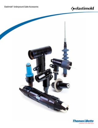
  • 5. Elastimold ® Underground Cable Accessories In this section... Elastimold® Underground Cable Accessories Overview....................................................................................2–3 200-Amp Loadbreak Elbows.......................................................4–7 200-Amp Deadbreak Elbows......................................................8–9 600-Amp Elbow Connectors................................................... 10-21 600-Amp Separable Cable Joints............................................ 22-23 Multi-Point Junctions.............................................................. 24-25 ComboT Integral Separable Connectors.................................. 26-30 Permanent Distribution Cable Joints....................................... 34-35 Shrink-Fit Cable Joints............................................................ 31-33 Distribution Shrink-Fit Terminations........................................ 36-42 Pre-Molded Terminations..............................................................43 Cable Shield Adapters and Jacket Seals................................. 44-45 Equipment Bushings.....................................................................46 Medium-Voltage Cable Accessories Technical Information............................................................. 47-52 Shielded Surge Arresters........................................................ 53-59 Transmission Cable Joints...................................................... 60-63 Transmission Cable Terminations........................................... 64-65 Transmission Cable Accessories Installation Tools........................66 Transmission Cable Accessories Technical Information.................67 L-Kits and Vault Stretcher Kits Ordering Information......................68
  • 6. www.tnb.com United States Tel: 901.252.8000 800.816.7809 Fax: 901.252.1354 Technical Services Tel: 888.862.3289 2 Overview Power& HighVoltage—Elastimold® UndergroundCableAccessories Elastimold® Separable Connectors, Cable Joints, Cable Terminators and other cable accessory products have been designed and tested per applicable portions of IEEE, ANSI and other industry standards including: • IEEE 386™ Standard for Separable Connectors • IEEE 404™ Standard for Cable Joints and Splices • IEEE 48™ Standard for Cable Terminations • IEEE 592™ Standard for Exposed Semiconducting Shields • ANSI C119.4 Standard for Copper and Aluminum Conductor Connectors • AEIC CS8 Standards for XLP and EPR Insulated Cables • ICEA S-94-649-2004 and S-97-682-2000 Standard for Cables Rated 5,000 – 46,000 Volts Cable Joints And Terminations Ratings Refer to the pages listed below for rating information: • PCJ™ Cable Joints, page 32 • SFJ Shrink Fit™ Cable Joints, page 29 • Cable Terminations, page 34 Separable Connector Ratings The following chart shows voltage and current ratings which apply to all Separable Connectors including 200-Amp Loadbreak, 200-Amp Deadbreak and 600 Series Deadbreak products. The next chart shows switching and fault close ratings which only apply to 200-Amp Load-Break Connectors. Application Information: 1. Load-Break connectors are designed and rated for use on grounded WYE systems. For application on ungrounded WYE or delta systems, the next higher voltage class product is recommended. Examples: 5kV ungrounded: use 15kV class products; 15kV ungrounded: use 25kV class products; 25kV ungrounded: use 35kV class products. 2. Products are designed and constructed for all applications including padmount, subsurface, vault, indoor, outdoor, direct sunlight, direct buried and continuously submerged in water. 3. Products are designed and rated for ambient temperatures of -40° C to +65° C. It is recommended that loadbreak connectors be hotstick operated at -20° C to +65° C ambient temperature range and at altitudes not exceeding 6000 feet. Voltage and Current Ratings 15kV CLASS RATINGS 25kV CLASS RATINGS 35kV CLASS RATINGS Operating Voltage Maximum line-to-ground (See Application Info Note 1) 8.3kV 15.2kV 21.1kV BIL Impulse withstand 1.2 x 50 microsecond wave 95kV 125kV 150kV Withstand Voltage AC One Minute DC Fifteen Minute 34kV 53kV 40kV 78kV 50kV 103kV Corona Extinction Level @ 3pC Sensitivity 11kV 19kV 26kV 200-Amp Products Continuous Current: Symmetrical Momentary Current: 600 Series Products Continuous Current Symmetrical Momentary Current: 200 Amp 10kA sym, 10 cycle duration* 600 and 900 Amp 25kA sym, 10 cycle duration* * Designed for 90° C maximum continuous operating temperature. Switching and Fault Close Ratings LOADMAKE/LOADBREAK SWITCHING FAULT CLOSE 15kV CLASS RATINGS • 1ø and 3ø circuits 8.3kV line to ground, 14.4kV max. across open contacts • 10 loadmake/break operations at 200 Amps max. with 70 to 80% lagging power factor 1 fault close operation at 8.3kV or 14.4kV; 10,000 amps RMS sym; 10 cycles (.17 sec.) 1.3 max. asym factor applies to new or used mating parts (up to maximum designated switching operations) 25kV CLASS RATINGS • 1ø and 3ø circuits 15.2kV line to ground, 26.3kV max. across open contacts • 10 loadmake/break operations at 200 Amps max. with 70 to 80% lagging power factor 1 fault close operation at 15.2kV or 26.3kV; 10,000 amps RMS sym; 10 cycles (.17 sec.) 1.3 max. asym factor applies to new or used mating parts (up to maximum designated switching operations.) 35kV CLASS RATINGS • 1ø and 3ø circuits 21.1kV line to ground, 36.6kV max. across open contacts. • 10 loadmake/break operations at 200 Amps max. with 70 to 80% lagging power factor. 1 fault close operation at 21.1kV or 36.6kV; 10,000 amps RMS sym; 10 cycles (.17 sec.) 1.3 max. asym factor applies to new or used mating parts (up to maximum designated switching operations)
  • 7. United States Tel: 901.252.8000 800.816.7809 Fax: 901.252.1354 Technical Services Tel: 888.862.3289www.tnb.com 3 Power HighVoltage—Elastimold® UndergroundCableAccessories Overview IEEE Standard 386 defines the specific interface dimensions that 200 Amp and 600 Series elbows, inserts, junctions, equipment bushings and any mating components must conform to ensure interchangeability. The table below provides information concerning the types of interfaces supplied by Elastimold® for various applications and is useful to ensure proper matching of components. Standard Interfaces for Separable Connectors, Components and Equipment Bushings Note: 1. Elastimold® uses Fig. 7 interface for both 25 and 35kV applications. BUSHING INTERFACE VOLTAGE CLASS INTERFACE DESCRIPTION STANDARD NO. FIGURE NO. 200-AMP DEEPWELL EQUIPMENT BUSHING 15kV, 25kV and 35kV 200-Amp Bushing Well Interface 8.3kV, 15.2kV and, 21.1kV IEEE 386-2001 Fig. 3 200-AMP LOADBREAK INSERT 15kV 200-Amp Loadbreak 8.3kV and 8.3kV/14.4kV IEEE 386-2001 Fig. 5 200-AMP LOADBREAK INSERT 25kV 200-Amp Loadbreak 15.2kV and 15.2kV/26.3kV IEEE 386-2001 Fig. 7, Note 1 200-AMP LOADBREAK INSERT 35kV 200-Amp Loadbreak Interface No. 2 21.1kV and 21.1kV/36.3kV IEEE 386-2001 Fig. 7, Note 1 200-AMP DEADBREAK INSERT 15kV and 25kV 200-Amp Deadbreak 8.3kV and 15.2kV IEEE 386-2001 Fig. 4 600 SERIES EQUIPMENT BUSHING 15kV and 25kV 600-Amp Deadbreak Interface No.1 8.3kV and 15.2kV IEEE 386-2001 Fig.11 600 SERIES EQUIPMENT BUSHING 35kV 600-Amp Deadbreak Interface No.1 21.1kV IEEE 386-2001 Fig.13 A C D E F G B A C D E F G B
  • 8. www.tnb.com United States Tel: 901.252.8000 800.816.7809 Fax: 901.252.1354 Technical Services Tel: 888.862.3289 4 200-Amp Loadbreak Elbows Power HighVoltage—Elastimold® UndergroundCableAccessories CABLE TO EQUIPMENT CONNECTIONS OPERATING ACCESSORIES BUSHING WELL PLUG BUSHING WELL LOADBREAK BUSHING INSERT EXTENDED BUSHING INSERT LOADBREAK FEED-THRU INSERT BOLTED ELBOW W/TAP INSULATED PARKING BUSHING GROUNDING PLUG PARKING STAND FEED THRU See pages 51-57 for surge arrester applications LOADBREAK ELBOW CONNECTOR WITH OR WITHOUT TEST POINT SEE CABLE NOTES SEE CABLE NOTES SEE CABLE NOTES GROUNDING ELBOW REPAIR ELBOW REPLACEMENT ELBOW FUSED ELBOW INSULATED CAP INSULATED CAP WITH GROUND TEST ROD ASSEMBLY TOOL 200-Amp Loadbreak Connectors and Accessories 200-Amp Loadbreak Connectors and Accessories provide a convenient method to connect/disconnect cable and equipment on power distribution systems. Loadbreak elbows include provisions for energized operation using standard hotstick tools, allowing loadmake/ break operation and a visible disconnect. Components can be isolated with insulated caps, plugs and parking bushings. Optional accessories allow system grounding, testing, bypass, surge protection and current limiting fusing. Additional connecting points and taps can be provided by use of junctions or feed-thrus. Ratings Overview See page 2 for complete information, including switching and fault close ratings. Current Ratings 200A Continuous 10kA sym. 10 Cycles Voltage Ratings 15kV Class 8.3kV Phase-to-Ground 14.4kV Phase-to-Phase 95kV BIL 34kV AC Withstand 53kV DC Withstand 11kV Corona Extinction 25kV Class 15.2kV Phase-to-Ground 26.3kV Phase-to-Phase 125kV BIL 40kV AC Withstand 78kV DC Withstand 19kV Corona Extinction 35kV Class 21.1kV Phase-to-Ground 36.6kV Phase-to-Phase 150kV BIL 50kV AC Withstand 103kV DC Withstand 26kV Corona Extinction 200-Amp Loadbreak Separable Connector Components
  • 9. United States Tel: 901.252.8000 800.816.7809 Fax: 901.252.1354 Technical Services Tel: 888.862.3289www.tnb.com 5 Power HighVoltage—Elastimold® UndergroundCableAccessories 200-Amp Loadbreak Elbows ILLUSTRATION (NOT TO SCALE) DESCRIPTION VOLTAGE CLASS CAT. NO. NOTES Grounding Plug (1/0 AWG x 6' Ground Lead) 15kV 25kV 161GP 272GP Grounding Elbow (1/0 AWG x 6' Ground Lead) 15kV 25/35kV 160GLR 370GLR N12 Feed-Thru 15kV 25kV 35kV 35kV 164FT 274FT 371FT 373FT N6, N18 Feed-Thru Vertical 15kV 25kV 35kV 164FTV 274FTV 373FTV Adjustable Bracket 2-Point Feed-Thru 15kV 25kV 35kV 164FT2-AB 274FT2-AB 373FT2-AB N22 N22 N22 Adjustable Bracket 3-Point Feed-Thru 15kV 25kV 35kV 164FT3-AB 274FT3-AB 373FT3-AB N22 N22 N22 Adjustable Bracket 4-Point Feed-Thru 15kV 25kV 35kV 164FT4-AB 274FT4-AB 373FT4-AB N22 N22 N22 Feed-Thru Well 15/25kV K1601WFT Feed-Thru Well Vertical 15/25kV K1601WFTV Insulated Parking Bushing 15kV 25kV 35kV 161SOP 272SOP 372SOP N20 Insulated Parking Bushing 15kV 25kV 164SOP 274SOP N22 N22 Test Rod All 200AT Bushing Well Plug 15/25kV 35kV 276BWP M276BWP Assembly Tool All 370TR N8 ILLUSTRATION (NOT TO SCALE) DESCRIPTION VOLTAGE CLASS CAT. NO. NOTES Elbow Connector 15kV 25kV 35kV 165LR-W5X Use Tables W1 and X1 275LR-W5X Use Tables W16 and X1 375LR-W5X Use Tables W3 and X2 N2, 3, 4, 5 N2, 3, 4, 5 N2, 3, 5 Elbow Connector w/ Test Point 15kV 25kV 35kV 166LR-W5X Use Tables W1 and X1 276LR-W5X Use Tables W16 and X1 376LR-W5X Use Tables W3 and X2 N2, 3, 4, 5, 23 N2, 3, 4, 5, 23 N2, 3, 5, 23 Jacket Seal Elbow Connector 15kV 25kV 165LRJS-W5X Use Tables W1 and X1 275LRJS-W5X Use Tables W16 and X1 N2, 19 N2, 19 Jacket Seal Elbow Connector w/ Test Point 15kV 25kV 166LRJS-W5X Use Tables W1 and X1 276LRJS-W5X Use Tables W16 and X1 N2, 19, 23 N2, 19, 23 Repair Elbow Connector 15kV 25kV 167ELR-W5X Use Tables W5 and X1 273ELR-W5X Use Tables W5 and X1 N5, 10, 18 N5, 10, 18 Repair Elbow Connector w/ Test Point 15kV 25kV 168ELR-W5X Use Tables W5 and X1 274ELR-W5X Use Tables W5 and X1 N5, 10, 18, 23 N5, 10, 18, 23 Replacement Elbow 15kV 25kV 167RLR-W5X Use Tables W4 and X1 273RLR-W5X Use Tables W2 and X1 N5, 11, 13 N5, 11, 13 Replacement Elbow w/ Test Point 15kV 25kV 168RLR-W5X Use Tables W4 and X1 274RLR-W5X Use Tables W2 and X1 N5, 11, 13, 23 N5, 11, 13, 23 Direct Test Elbow Connector 15kV 25kV 167DLR-W5X Use Tables W4 and X1 273DLR-W5X Use Tables W2 and X1 N2, 5, 21 N2, 5, 21 Direct Test Repair Elbow Connector 15kV 25kV 167DELR-W5X Use Tables W5 and X1 273DELR-W5X Use Tables W5 and X1 N5, 10, 18, 21 N5, 10, 18, 21 Direct Test Repair Elbow Connector w/Test Point 15kV 25kV 168DELR-W5X Use Tables W5 and X1 274DELR-W5X Use Tables W5 and X1 N5, 10, 18, 21, 23 N5, 10, 18, 21, 23 Fused Elbow (Full Range Current Limiting) 15kV 25kV 168FLR W0X 274FLR W0X N23 N23 Bolted Elbow w/ Tap 15kV 167LRT-W5X Use Tables W4 and X1 N17 Bushing Insert 15kV 25kV 35kV 35kV 1601A4 2701A4 3701A4 3701A3 N4, 8 N4, 8 N6, 20 20 Extended Bushing Insert 15kV 25kV 1601EA4 2701EA4 N8 N8 Feed-Thru Insert 15kV 25kV 35kV 1602A3R 2702A1 3702A1 N16 N16 N6, 16 Insulated Cap 15kV 160DR N9 Insulated Cap w/ Ground 15kV 15kV 25kV 35kV 160DRG 167DRG 273DRG 375DRG N9 N7, 9 N7, 9 N7, 9 Insulated Cap w/ Ground and Test Point 15kV 25kV 35kV 168DRG 274DRG 376DRG N7 N7 N7 Refer to the W and X tables on page 50 for sizing to cable insulation diameter and conductor size. For cable shield adapters and jacket seals, see page 42. N1. Copper lug for use on COPPER CONDUCTOR ONLY. N2. W5X indicates that the catalog number includes 02500X long bi-metal compression lug as standard. For an all-copper lug, replace W5X with W2X in Table X1 to specify the all-copper 02702X lug. N3. Also available as housing only. Specify: 165BLR-W; 275BLR-W; 375BLR-W; 166BLR-W; 276BLR-W; 376BLR-W. N4. Also available as elbow/insert combination. Specify: 165A4-WX; 275A4-WX; 166A4-WX; 276A4-WX. N5. Also available with 200ECS jacket seal included. Add - “S” suffix to catalog number. N6. Rated for single-phase applications only. N7. Equipped with insulated cuff. N8. Includes internal torquing feature using 200AT Assembly Tool. N9. Also available without probe. Specify “A” suffix - Example: 273DRGA. N10. Repair elbow has extended length contact and elbow housing resulting in a net gain of 31 ⁄4 in length. N11. Replacement elbow has extended-length contact and elbow housing resulting in a net gain of 87 ⁄8 in length. N12. Rated for 25kV thru 35kV applications. N13. Includes long bi-metal contact 00400X. N14. 160CA Cable Size Adapter can only be used with elbow part numbers 165LR/166LR C size only. N16. Fully rotatable for 360° positioning. Includes bail assembly to secure feed-thru insert to bushing well. N17. Includes 02800X bi-metal contact. N18. Includes 02509X long bi-metal contact. N19. Includes built-in jacket seal. Also available as housing only — specify: 165BLRJS-W, 166BLRJS-W, 275BLRJS-W or 276LRJS-W. Also available as elbow/insert combination — specify: 165JSA4-W5X, 166JSA4-W5X, 275JSA4-W5X or 276JSA4-W5X. N20. Includes a black vent ring. N21. Direct Test Connectors, along with a 200TC-X series meter adapter, a properly rated voltage meter and Hot-line Stick provide a means for direct conductor voltage testing. N22. With stainless steel bracket. N23. Test Point Cap catalog number 156-7 N24. Add suffix “-SS” for stainless steel bracket.
  • 10. www.tnb.com United States Tel: 901.252.8000 800.816.7809 Fax: 901.252.1354 Technical Services Tel: 888.862.3289 6 200-Amp Loadbreak Elbows Power HighVoltage—Elastimold® UndergroundCableAccessories 200-Amp Loadbreak Separable Connector Components CABLE TO CABLE CONNECTIONS 4-POINT JUNCTION 3-POINT JUNCTION 2-POINT JUNCTION 2 POINT WELL JUNCTION 3-POINT WELL JUNCTION 4-POINT WELL JUNCTION LOADBREAK BUSHING INSERT LOADBREAK BUSHING INSERT LOADBREAK BUSHING INSERT Ratings Overview See page 2 for complete information, including switching and fault close ratings. Current Ratings 200A Continuous 10kA sym. 10 Cycles Voltage Ratings 15kV Class 8.3kV Phase-to-Ground 14.4kV Phase-to-Phase 95kV BIL 34kV AC Withstand 53kV DC Withstand 11kV Corona Extinction 25kV Class 15.2kV Phase-to-Ground 26.3kV Phase-to-Phase 125kV BIL 40kV AC Withstand 78kV DC Withstand 19kV Corona Extinction 35kV Class 21.1kV Phase-to-Ground 36.6kV Phase-to-Phase 150kV BIL 50kV AC Withstand 103kV DC Withstand 26kV Corona Extinction 200-Amp Loadbreak Connectors and Accessories (continued) See pages 51-57 for surge arrester applications
  • 11. United States Tel: 901.252.8000 800.816.7809 Fax: 901.252.1354 Technical Services Tel: 888.862.3289www.tnb.com 7 Power HighVoltage—Elastimold® UndergroundCableAccessories 200-Amp Loadbreak Elbows ILLUSTRATION (NOT TO SCALE) DESCRIPTION VOLTAGE CLASS CAT. NO. NOTES Contacts: LR Long Bi-Metal ELR Bi-Metal LR Copper LRT Contact RLR Contact All 15/25kV All 15kV 15/25kV Use Table X1 02500X 02509X 02702X 02800X 00400X N1 N2 N3 Elbow Probe 15kV 25kV 35kV 166LRF 274LRF 375LRF Elbow Cable Entrance Insulating Plug All 10EP-W Use Table W6 Cable Size Adapter 15kV 160CA-W Use Table W6 EB-FA Only N4 Direct Voltage Test Meter Adapter for: HD Electric Meters All 200TC-1 N14 Ross Meters 200TC-2 N14 Chance Meters 200TC-4 N14 2-Way Well Junction w/ S.S. Bracket 15/25kV K1601WJ2 N6 2-Way Well Junction w/ “U” Straps 15/25kV K1601WJ2-5 N5, 6, 11 3-Way Well Junction w/ S.S. Bracket 15/25kV K1601WJ3 N6 3-Way Well Junction w/ “U” Straps 15/25kV K1601WJ3-5 N5, 6, 12 4-Way Well Junction w/ S.S. Bracket 15/25kV K1601WJ4 N6 4-Way Well Junction w/ “U” Straps 15/25kV K1601WJ4-5 N5, 6, 13 2-Point Junction with/Stainless Steel Bracket 15kV 25kV 35kV 164J2 274J2 373J2 N7 N7 N7 2-Point Junction w/“U” Straps 15kV 25kV 35kV 164J2-5 274J2-5 373J2-5 N5, 8 N5, 11 N5, 11 3-Point Junction with Stainless Steel Bracket 15kV 25kV 35kV 164J3 274J3 373J3 N7 N7 N7 3-Point Junction w/“U” Straps 15kV 25kV 35kV 164J3-5 274J3-5 373J3-5 N5, 9 N5, 12 N5, 12 4-Point Junction with Stainless Steel Bracket 15kV 25kV 35kV 164J4 274J4 373J4 N7 N7 N7 4-Point Junction w/“U” Straps 15kV 25kV 35kV 164J4-5 274J4-5 373J4-5 N5, 10 N5, 13 N5, 13 N1. Repair elbow has extended-length contact and elbow housing resulting in a net gain of 31 ⁄4 in length. N2. Copper lug for use on COPPER CONDUCTOR ONLY. N3. Replacement elbow has extended-length contact and elbow housing resulting in a net gain of 87 ⁄8 in length. N4. 160CA Cable Size Adapter can only be used with elbow catalog numbers 165LR/166LR C, H or CC size only. N5. Also available as rubber only, without straps. Specify suffix “-4” in place of “-5” in the catalog number. N6. Supplied with replaceable stud. Replacement stud available separately. Specify 1000-150. N7. Hardware packages, consisting of brackets and straps only, may be ­ordered separately by specifying “-6” in the catalog number. Example 164J4-6. N8. Hardware package, consists of “U” straps and back plate only, may be ordered separately by specifying 1601US-J2. N9. Hardware package, consists of “U” straps and back plate only, may be ordered separately by specifying 1601US-J3. N10. Hardware package, consists of “U” straps and back plate only, may be ordered separately by specifying 1601US-J4. N11. Hardware package, consists of “U” straps and back plate only, may be ordered separately by specifying 271-68. N12. Hardware package, consists of “U” straps and back plate only, may be ordered separately by specifying 271-61. N13. Hardware package, consists of “U” straps and back plate only, may be ordered separately by specifying 271-70. N14. For use with Direct Test Connectors. Refer to the W and X tables on page 50 for sizing to cable insulation diameter and conductor size. For cable shield adapters and jacket seals, see page 42.
  • 12. www.tnb.com United States Tel: 901.252.8000 800.816.7809 Fax: 901.252.1354 Technical Services Tel: 888.862.3289 8 200-Amp Deadbreak Elbows Power HighVoltage—Elastimold® UndergroundCableAccessories LOCKING AND REPAIR SPLICE LOCKING “Y” SPLICE FEED THRU PARKING STAND STAND-OFF PLUG INTEGRAL BUSHING GROUNDING PLUG INSULATED PLUG STRAIGHT PLUG IN-LINE JUNCTION TEE SPLICE BUSHING WELL BUSHING INSERT BUSHING WELL PLUG DEADBREAK FEED-THRU INSERT 3-POINT JUNCTION 4-POINT JUNCTION 2-POINT JUNCTION CABLE TO EQUIPMENT OPERATING ACCESSORIES CABLE TO CABLE CONNECTIONS 200-Amp Deadbreak Connectors and Accessories 200-Amp Deadbreak Connectors and Accessories provide a quick- disconnect feature for cable and equipment connections on power distribution systems. All deadbreak connectors must be de-­energized before operating and must be mechanically secured with bails when connected. Components can be isolated with insulated caps, plugs and parking bushings. All deadbreak elbows are equipped with test points as standard. Optional accessories allow system grounding, bypass and lightning surge protection. Additional connecting points and taps can be provided by use of junctions or feed-thrus. Ratings Overview See page 2 for complete information. Current Ratings 200A Continuous 10kA sym. 10 Cycles Voltage Ratings 15kV Class 8.3kV Phase-to-Ground 14.4kV Phase-to-Phase 95kV BIL 34kV AC Withstand 53kV DC Withstand 11kV Corona Extinction 25kV Class 15.2kV Phase-to-Ground 26.3kV Phase-to-Phase 125kV BIL 40kV AC Withstand 78kV DC Withstand 19kV Corona Extinction 200-Amp Deadbreak Separable Connector Components Except for locking splices all 200A deadbreak products must be mechanically secured with a bail when connected See pages 51-57 for surge arresters applications INSULATED CAP STRAIGHT RECEPTACLE ELBOW CONNECTOR
  • 13. United States Tel: 901.252.8000 800.816.7809 Fax: 901.252.1354 Technical Services Tel: 888.862.3289www.tnb.com 9 Power HighVoltage—Elastimold® UndergroundCableAccessories 200-Amp Deadbreak Elbows ILLUSTRATION (NOT TO SCALE) DESCRIPTION VOLTAGE CLASS CAT. NO. NOTES Bail 15/25kV 150TB4 N5 Bail 15/25kV 150TB5 N5 Bail 15/25kV 150TB6 N5 Contacts: Long Bi-Metal Copper 15/25kV 15/25kV 02500X 02702X N7 Elbow Cable Entrance Insulating Plug 15/25kV 10EP-W Use Table W6 N10 Cable Entrance Insulating Plug 15/25kV 152EA-W Use Table W6 N11 Cable Size Adapter 15/25KV 160CA-W Use Table W6 EB-FA Only N14 ILLUSTRATION (NOT TO SCALE) DESCRIPTION VOLTAGE CLASS CAT. NO. NOTES Elbow Connector w/ Test Point 15/25kV 156LR-W5X Use Tables W4 and X1 N1, 2 Direct Test Elbow Connector 15/25kV 156DLR-W5X Use Tables W4 and X1 N1, 2, 22 Bail Assembly for 156LR Elbow 15/25kV 150BA Bushing Insert 15/25kV K1501A1 N3 Feed-Thru Insert 15/25kV K1502A1 N3, 4 Insulated Plug 15/25kV K150DP N3 Insulated Cap 15/25kV K150DR N3 Insulated Parking Bushing 15/25kV K151SOP N3 Grounding Plug 15/25kV 151GP N3 Feed-Thru 15/25kV K1501FT N3, 6 2-Point Junction 15/25kV K1501J2-U8 N3, 6 3-Point Junction 15/25kV K1501J3-U8 N3, 6 4-Point Junction 15/25kV K1501J4-U8 N3, 6 Elbow Probe 15/25kV 156LRF Straight Receptacle 15/25kV K151SR-W0X Use Tables W1 and X1 N3, 12, 13, 17, 18 Straight Plug 15/25kV K151SP-W0X Use Tables W1 and X1 N3, 12, 13, 19 Tee Splice 15/25kV K150T N3 In-Line Junction 15/25kV K150S N3 Locking Splice/ Repair Splice 15/25kV K151LS-W0X Use Tables W1 and X1 N8, 9, 13, 15, 16, 17, 20, 23 Locking “Y” Splice 15/25kV K151LY-W0X Use Tables W1 and X1 N8, 9, 13, 15, 17, 21 Bail 15/25kV 150TB1 N5 Bail 15/25kV 150TB2 N5 Bail 15/25kV 150TB3 N5 N1. Includes bail assembly. N2. W5X indicates that the catalog number includes a 02500X bi-metal compression lug, which is rated for either aluminum or copper conductor, as standard. For an all-copper lug, replace W5X with W2X. Use Table X1 to specify the all-copper 02702X lug. N3. Bails are required but not included. Order separately. Consult factory for bails not listed for a specific application. N4. Fully rotatable for 360° positioning. Includes bail assembly to secure feed-thru insert to bushing well. Elbows bail assemblies are required but not included with the feed-thru insert. N5. Refer to factory for application details. N6. Center-to-center spacing equals 4 inches. N7. Copper lug for copper cable only. N8. To order cable legs for different cable sizes, list each leg size “W” and “X”. Example: K151LY-A1240-A1240-B1220. See Tables W1 and X1 for sizes. N9. To order locking contacts for K151LS and K151LY, order 01401X (Al) or 01402X (Cu) for plug contact. Order 01301X (Al) or 01302X (Cu) for receptacle. See Table X1 for sizes. N10. For use with 156LR elbows. N11. For use with K151SR, K151SP, K151LS, K151LY receptacles, plugs and splices. N12. Also available as housing only. Specify K151BSP-W or K151BSR-W. N13. Also available in EB-FA sizes per Table W6 by using 160CA cable adapter with C size plugs and receptacles. N14. 160CA cable adapter can only be used with C size plugs and receptacles. N15. Bails are not required for locking splices. N16. When used as a repair splice, the assembled length allows 4 for cable­replacement/repair. N17. Straight receptacles are also available with test point. Specify K152SR-W0X catalog number. N18. W0X indicates that the catalog number includes a 01500X universal aluminum compression lug, which is rated for either aluminum or copper, as standard. For an all-copper lug, replace W0X with W2X in Table X1 to specify the all-copper 01502X lug. N19. W0X indicates that the catalog number includes a 01600X universal aluminum compression lug, which is rated for either aluminum or copper, as standard. For an all-copper lug, replace W0X with W2X in Table X1 to specify the all-copper 01602X lug. N20. W0X indicates that the catalog number includes a 01400X universal aluminum compression lug, which is rated for either aluminum or copper, as standard. For an all-copper lug, replace W0X with W2X in Table X1 to specify the all-copper 01402X lug. N21. W0X indicates that the catalog number includes a 01300X universal aluminum compression lug, which is rated for either aluminum or copper, as standard. For an all-copper lug, replace W0X with W2X in Table X1 to specify the all-copper 01302X lug. N22. Direct Test Connectors, along with a 200TC-X series meter adapter, a properly rated voltage meter and Hot-line Stick provides a means for direct conductor voltage testing. See page 7 for meter adapters. N23. Gains approximately 4 of repair length. Refer to the W and X tables on page 50 for sizing to cable insulation diameter and conductor size. For cable shield adapters and jacket seals, see page 42.
  • 14. www.tnb.com United States Tel: 901.252.8000 800.816.7809 Fax: 901.252.1354 Technical Services Tel: 888.862.3289 10 600-Amp Elbow Connectors Power HighVoltage—Elastimold® UndergroundCableAccessories 600 Series deadbreak elbows, straight receptacles, junctions, vault stretchers and accessories are used to connect equipment and cable on primary feeder and network circuits. Designs accommodate large conductors and feature bolted connections and deadfront modular construction for maximum reliability, performance and versatility. De-energized connectors can be quickly and easily connected and disconnected using standard hand tools and equipment in accordance with accepted operating practices. Optional accessories allow visible external separation, bypass, isolation, dead-ending, grounding and testing as well as adding taps, surge arresters and circuit protection. Hotstick-operable and separable joint systems are shown on pages 16–19 and 20–21. Spiking Aid-T When spiking a medium voltage cable near a stacked T-Body cable joint, the Elastimold® Spiking-T is a specially designed product to reduce outage time and cost. Medium voltage cable is spiked as a means to assure the circuit is de-energized where there is no sectionalizing device, direct testing means or provision for grounding. One leg of stacked T-Body cable joint is spiked/cut with a grounded guillotine type cable cutter, near the T-Body intersection. Once spiked and proved de-energized, the cable is re-prepped and a Spiking-T with a lug extender is assembled and reconnected to the stack. If this stack ever needs to be spiked again, the Spiking-T provides a convenient place to spike, no additional cable prep required, just replace the Spiking-T and the lug extender, reduced outage, reduced cost. GAD When your available fault currents exceed 10kA in your underground systems, the Elastimold® GAD may be your answer. The Elastimold® GAD is rated 25kA and installs in the rear interface of a 600 Series elbow connector (T-Body). The GAD is normally covered and insulated with an insulating cap that contains capacitive test and a hot stick operating band. Once the circuit is opened at a disconnecting device, the test point cap is removed with a hot-stick, and then using an appropriate capacitive test point meter the test point is checked for voltage. Then the insulting cap is removed with a hot stick and a high voltage meter is used to confirm the de-energized state before a ground cable is connected. No need to remove basic insulating plug, no need to install temporary grounding adapters, the Elastimold® GAD is there when you need it. Also available in a Ball GAD version. 600 Series Deadbreak Components
  • 15. United States Tel: 901.252.8000 800.816.7809 Fax: 901.252.1354 Technical Services Tel: 888.862.3289www.tnb.com 11 Power HighVoltage—Elastimold® UndergroundCableAccessories 600-Amp Elbow Connectors STRAIGHT RECEPTACLE HOUSING STRAIGHT RECEPTACLE STRAIGHT RECEPTACLE ADAPTER BOLT WASHER COMPRESSION LUG CABLE ADAPTER RETAINING RING † † *†• SEE PAGES 18–19 SEE PAGES 22–23 FOR ADDITIONAL JUNCTIONS SEE PAGES 18–19 HOTSTICK OPERABLE 600 SERIES CONNECTORS - SEE PAGES 16–19 SEE PAGES 16–17 TEST AND GROUND CABLE TO EQUIPMENT ELBOW CONNECTOR 200A TAPS 600 SERIES TAPS CABLE TO CABLE UTILIZING L-KITS SEE PAGES 14–15 CABLE TO CABLE (UTILIZING JUNCTIONS) INTEGRAL BUSHING THREADED STUD BUSHING EXTENDER CONNECTING PLUG 2 PT JUNCTION 3 PT JUNCTION 4 PT JUNCTION OPERATING ACCESSORIES GROUNDING PLUG INSULATED PARKING BUSHING THREADED COMPRESSION LUG STICK-OP LOADBREAK REDUCING TAP PLUG STICK-OP CAM-OP RETAINER SLEEVES CAM-OP LINK CONNECTOR CAM-OP CABLE ADAPTER COMPRESSION LUG VAULT STRETCHER THREADED STUD VAULT STRETCHER CONNECTOR COMPRESSION LUG CABLE ADAPTER THREADED STUD INSULATED CAP WITH TEST POINT BUSHING EXTENDER CABLE ADAPTER COMPRESSION LUG THREADED STUD 600 SERIES ELBOW INSULATED PLUG VOLTAGE DETECTION CAP CONNECTING PLUG 200A DEADBREAK SEE PAGES 8–9 200A LOADBREAK SEE PAGES 4–7 SPANNER WRENCH DEADBREAK REDUCING TAP PLUG REDUCING TAP WELL LOADBREAK ELBOW TAP PLUG CABLE TO CABLE UTILIZING VAULT STRETCHERS SEE PAGES 14–15 See pages 51–57 for surge arrester applications 600 Series Deadbreak Components Voltage Ratings 15/25kV Class (5kV thru 28kV) 16.2kV Phase-to-Ground 28kV Phase-to Phase 140kV BIL 45kV AC Withstand 84kV DC Withstand 21.5kV Corona Extinction 35kV Class 21.1kV Phase-to-Ground 36.6kV Phase-to-Phase 150kV BIL 50kV AC Withstand 103kV DC Withstand 26kV Corona Extinction Note: Elastimold has increased the IEEE Standard Prod­uction and Design Test levels for 25kV Class products to include 27kV and 28kV systems. * Tested at 8.3/14.9kV † Tested at 15.2/26.3kV • Tested at 21.1/36.6kV Ratings Overview See page 2 for complete information. Current Ratings (Prefixes: 650, K650, K651, K655, K656, 750, 755, 756 03700) 600 Amp Continuous 25kA sym.,10 cycles (Prefixes 675, K671, K675, K676, 775, 776 03702) 900 Amp Continuous 25kA sym.,10 cycles Note: 900-amp ratings require copper cable and copper current- carrying components.
  • 16. www.tnb.com United States Tel: 901.252.8000 800.816.7809 Fax: 901.252.1354 Technical Services Tel: 888.862.3289 12 600-Amp Elbow Connectors Power HighVoltage—Elastimold® UndergroundCableAccessories ILLUSTRATION (NOT TO SCALE) DESCRIPTION VOLTAGE CLASS CAT. NO. NOTES 600 Series Elbow (w/ Insul. Plug, Cap, Stud, Lug and Cable Adapter) 15/25kV 35kV K655LR-W0X Use Tables W7 and X6 755LR-W0X Use Tables W9 and X6 N1, 2 N1, 2, 15 600 Series Direct Test Elbow (w/ Insul. Plug, Cap, Stud Lug and Cable Adapter) 15/25kV 35kV K655DLR-W0X Use Tables W7 and X6 755DLR-W0X Use Tables W9 and X6 N1,2,12 N1,2,12,15 600 Series Elbow w/ Test Point (w/ Insul. Plug, Cap, Stud, Lug and Cable Adapter) 15/25kV 35kV K656LR-W0X Use Tables W7 and X6 756LR-W0X Use Tables W9 and X6 N1,2 N1,2,15 600 Series Direct Test Elbow w/Test Point (w/ Insul. Plug, Cap, Stud, Lug and Cable Adapter) 15/25kV 35kV K656DLR-W0X Use Tables W7 and X6 756DLR-W0X Use Tables W9 and X6 N1,2,12 N1,2,12,15 600 Series Elbow w/o Test Point Housing only (w/ Stud) 15/25kV 35kV K655BLR 755BLR N1, 3 N1, 3, 15 600 Series Elbow w/ Test Point Housing only (w/ Stud) 15/25kV 35kV K656BLR 756BLR N1, 3 N1, 3, 15 600 Series Replacement Elbow Housing only w/o Test Point 15/25kV K655BRLR N14 600 Series Replacement Elbow Housing only w/ Test Point 15/25kV K656BRLR N14 600 Series Spiking Elbow (w/ Spiking Contact) 15/25kV K656BSELR 600 Series Extended Elbow (w/ Extended Contact) 15/25kV K656BELR 600 Series Spiking Elbow (w/ Spiking Contact, Insul. Plug, Cap, Stud, Lug and Cable Adapter) 15/25kV K656SELR-W0X N2 600 Series Extended Elbow (w/ Extended Contact, Insul. Plug, Cap, Stud, Lug and Cable Adapter) 15/25kV K656ELR-W0X N2 600 Series Straight Receptacle (w/ Cable Adapter, Lug Retaining Ring) 15/25kV K655SR-W0X Use Tables W7 and X6 N1, 2, 11 600 Series Direct Test Straight Receptacle Elbow 15/25kV K655DSR-W0X Use Tables W7 and X6 N1,2,11,12 600 Series Straight Receptacle Housing (Lug Cable Adapter not included) 15/25kV K655BSR N1,11 Straight Receptacle Adapter 15/25kV K650SRA N1, 4 600 Series Vault Stretcher (Housing only w/ Stud) 15/25kV 35kV K655BVS 755BVS N1, 9 N1, 9 Cable Size Adapter 15/25kV 35kV 655CA-W Use Table W7 755CA-W Use Table W9 Compression Lug All All 03700X Use Table X6 03702X Use Table X6 N5 N6 600 Series Elbow Vault Stretcher Size Sensitive Kit (Cable Adapter Lug) 15/25kV 35kV 655CK-W0X Use Tables W7 and X6 755CK-W0X Use Tables W9 and X6 N2 N2 Adapter Retaining Ring ALL 650ARR-X Use Table X6 600 Series Straight Receptacle Size Sensitive Kit (Cable Adapter, Retaining Ring Lug) 15/25kV 655CK-W0X-ARR Use Tables W7 and X6 N2 K655/656SELR CIRCUITMUSTBEDE-ENERGIZEDDURINGCONNECTINGAND ANDSERIOUSINJUREMAYOCURE.USEAREMOTEGROUNDE ENSURETHATTHECIRCUITISDE-ENERGIZED.FOLLOWYO PROCEDUREBEFORECUTTING. HERE CUT CUT HERE K655/656SELR-WX CIRCUITMUSTBEDE-ENERGIZEDDURINGCONNECTINGAND ANDSERIOUSINJUREMAYOCURE.USEAREMOTEGROUNDE ENSURETHATTHECIRCUITISDE-ENERGIZED.FOLLOWYO PROCEDUREBEFORECUTTING. HERECUT CUTHERE
  • 17. United States Tel: 901.252.8000 800.816.7809 Fax: 901.252.1354 Technical Services Tel: 888.862.3289www.tnb.com 13 Power HighVoltage—Elastimold® UndergroundCableAccessories 600-Amp Elbow Connectors ILLUSTRATION (NOT TO SCALE) DESCRIPTION VOLTAGE CLASS CAT. NO. NOTES Bushing Extender (w/ Stud) 15/25kV 35kV K655BE 755BE N1, 3 N1, 3 Insulated Cap w/ Test Point (w/ Stud) 15/25kV K656DR N3, 7 Insulated Cap w/ Test Point (w/ Stud) Ground 15/25kV K656DRG N3, 7 Insulating Plug (w/Cap) 15/25kV 35kV K650BIP 750BIP N1, 7, 8 N1, 7, 8 Grounding Plug (Ground Lead 2/0 AWG x 30) 15/25kV 35kV 650GP 750GP N1, 7, 8 N1, 7, 8 600 Series Grounding Device 15/25kV K671GAD 600 Series Grounding Device with Ball 15/25kV K671BGAD 600 Series Insulating Cap for Grounding Device 15/25kV K676GADDR 600 Series Insulating Cap for Grounding Device with Ball 15/25kV K676BGADDR Insulated Parking Bushing 15/25kV 35kV K650SOP 750SOP N7, 8 N7, 8 Connecting Plug 15/25kV 35kV K651CP 750CP N1, 7, 8, 10 N1, 7, 8, 10 Deadbreak Reducing Tap Plug 15/25kV K650RTP N1, 7, 8, 9 Reducing Tap Well 15/25kV K650RTW N1, 7, 8, 9 Loadbreak Elbow Tap Plug 15kV 25kV 35kV 650ETP K650ETP 750ETP N1, 7, 8, 10 N1, 7, 8, 10 N1, 7, 8, 10 Vault Stretcher Threaded Stud 15/25kV 35kV 650VSA 750VSA N1 N1 600 Series Elbow Threaded Stud 15/25kV 35kV 650SA 750SA N1 N1 Assembly Tool (Window-OP) All 600ATM Spanner Wrench All 600SW N9 Direct Voltage Test Meter Adapter for: HD Electric Meters All 200TC-1 N12 Ross Meters 200TC-2 N12 Chance Meters 200TC-4 N12 N1. For 900-amp ratings, substitute 675 for 650 and 655; 676 for 656; K671 for K651; K675 for K650 and K655; K676 for K656; 775 for 750 and 755; 776 for 756 and 2X for 0X in the catalog number. The 900-amp rating requires copper current-carrying connector components and copper conductor cable. N2. Add suffix symbol from page 43 to include cable shield grounding kit and/or cable jacket sealing kit. N3. Available without the stud by adding “N” to the catalog number. N4. Straight Receptacle Adapter is used to connect Straight Receptacles K655YBSR and K655YSR-W0X (page 24) to equipment bushings. N5. Aluminum lug for use on aluminum or copper conductors. DO NOT substitute threaded 03600X lug. N6. Copper lug for use on COPPER CONDUCTOR ONLY. Do not substitute threaded 03602X lug. N7. Available with the stud factory-assembled by adding “SP” to the catalog number. 675ETP, K675ETP and 775ETP are available as -SP only. The stud is not field removable. N8. Available with a loose stud by adding suffix “S” to the catalog number. N9. 600SW spanner wrench is recommended for installation of deadbreak reducing tap plugs and reducing tap wells. N10. Use 600ATM Assembly Tool. N11. 600 Series Elbows and Straight Receptacles with IEEE Std. 386 capacitive test points are available by substituting 656 for 655; K656 for K655; K676 for K675; 756 for 755; 676 for 675; K676 for K675 and 776 for 775 in the catalog number. N12. Direct Test Connectors, along with a 200TC-X series meter adapter, a properly rated voltage meter and Hot-line Stick; provides a means for direct conductor voltage testing. N13. With stainless steel bracket. N14. Replacement Elbow includes an I-Adapter, and Straight Receptacle, resulting in a net gain of 20. N15. Available with 200kv BIL adding suffix “-200”. Refer to the W and X tables on page 50 for sizing to cable insulation diameter and conductor size. For cable shield adapters and jacket seals, see page 42. K671GAD Y 176 K D FOR A US E G O K676GADDRK671BGAD K651/671GAD K676BGADDR B Y 176 K D FOR A US E G O ELASTIMOLD R DEADBREAK 600AMP16.2kVL-G K651/671BGAD ELASTIMOLD R DEADBREAK 600AMP16.2kVL-G K671GAD Y 176 K D FOR A US E G O K676GADDRK671BGAD K651/671GAD K676BGADDR B Y 176 K D FOR A US E G O ELASTIMOLD R DEADBREAK 600AMP16.2kVL-G K651/671BGAD ELASTIMOLD R DEADBREAK 600AMP16.2kVL-G K671GAD Y 176 K D FOR A US E G O K676GADDRK671BGAD K651/671GAD K676BGADDR B Y 176 K D FOR A US E G O ELASTIMOLD R DEADBREAK 600AMP16.2kVL-G K651/671BGAD ELASTIMOLD R DEADBREAK 600AMP16.2kVL-G K671GAD Y 176 K D FOR A US E G O K676GADDRK671BGAD K651/671GAD K676BGADDR B Y 176 K D FOR A US E G O ELASTIMOLD R DEADBREAK 600AMP16.2kVL-G K651/671BGAD ELASTIMOLD R DEADBREAK 600AMP16.2kVL-G
  • 18. www.tnb.com United States Tel: 901.252.8000 800.816.7809 Fax: 901.252.1354 Technical Services Tel: 888.862.3289 14 Odering Information for Elastimold® Fuse Housings Power HighVoltage—Elastimold® UndergroundCableAccessories Nominal Fuse Voltage Rating Code 8.3kV 168 15.5kV 274 17.2kV 274 * Small Housing is used with 8.3kV (3–45A) and 15.5kV (6–20A) rated fuses. ** Large Housing is used with 8.3kV (65A and 80A) and 17.2kV (3–45A) rated fuses. NOTE: 1. All dimensions rounded up to the nearest eighth inch. 2. Also available with direct test port. 3. Dimensions with Direct Test Port units are 101⁄4” (260mm) or 105⁄8” (270mm). 4. 168FLR3 uses a large housing with a 15kV, 200A elbow interface. 168FLR1 274FLR1 168FLR3 274FLR3 F L R - Ø Housing Code Small* 1 Large** 3 Fuse Test Port Code Two Direct Test Ports A Two Capacitive Test Points Blank Cable Insulation Diameter (in.) Code 0.575”–0.740” 15–19mm A 0.635”–0.905” 16–23mm B 0.805”–1.060” 20–27mm C 0.890”–1.220” 25–31mm D Conductor Size Size (AWG) Stranded/ Solid/ Connector Compressed Compact Code 6 — 180 — 4 190 4 — 200 — 2 210 2 1 220 1 1/0 230 1/0 2/0 240 2/0 3/0 250 3/0 4/0 260 4/0 — 270 61 ⁄4” (159mm) 105 ⁄8” (270mm) 61 ⁄4” (159mm) 105 ⁄8” (270mm) 91 ⁄4” (235mm) A 105 ⁄8” (270mm) 101 ⁄2” (270mm) Indicates field that must be filled in to complete order. The following diagram shows how to construct a catalog number for Fuse Housings. A = 87 ⁄8” (225mm) A = 91 ⁄4” (235mm) 87 ⁄8” (225mm)
  • 19. United States Tel: 901.252.8000 800.816.7809 Fax: 901.252.1354 Technical Services Tel: 888.862.3289www.tnb.com 15 Power HighVoltage—Elastimold® UndergroundCableAccessories 600-Amp Elbow Connectors 8.3kV (3–45A)/15.5kV (6–20A) Fuse NOTE: All dimensions rounded up to the nearest eighth inch. Voltage Rating Code 8.3kV 083 15.5kV 155 17.2kV 172 Amperage Rating Code 3A 8.3/17.2kV 003 6A 8.3/15.5/17.2kV 006 8A 8.3/15.5/17.2kV 008 10A 8.3/15.5/17.2kV 010 12A 8.3/15.5/17.2kV 012 18A 8.3/15.5/17.2kV 018 20A 8.3/15.5/17.2kV 020 25A 8.3/17.2kV 025 30A 8.3/17.2kV 030 40A 8.3/17.2kV 040 45A 8.3/17.2kV 045 65A 8.3kV 065 80A 8.3kV 080 E F X - E 131 ⁄2” (343mm) 91 ⁄4” (235mm) 21 ⁄4” (54mm) Indicates field that must be filled in to complete order. The following diagram shows how to construct a catalog number for Full-Range Current-Limiting Fuses. 8.3kV (65–80A)/17.2kV (3–45A) Fuse 21 ⁄4” (54mm)
  • 20. www.tnb.com United States Tel: 901.252.8000 800.816.7809 Fax: 901.252.1354 Technical Services Tel: 888.862.3289 16 600-Amp Elbow Connectors Power HighVoltage—Elastimold® UndergroundCableAccessories 600 Series deadbreak elbows, straight receptacles, junctions, vault stretchers and accessories are used to connect equipment and cable on primary feeder and network circuits. Designs accommodate large conductors and feature bolted connections and deadfront modular construction for maximum reliability, performance and versatility. De-energized connectors can be quickly and easily connected and disconnected using standard hand tools and equipment in accordance with accepted operating practices. Optional accessories allow visible external separation, bypass, isolation, dead-ending, grounding and testing as well as adding taps, surge arresters and circuit protection. Hotstick operable and separable joint systems are shown on pages 16–19 and 20–21. Ratings Overview See page H–2 for complete information. Current Ratings (Prefixes: 650, K650, K651,K655, K656, 750, 755, 756 03700) 600 Amp Continuous 25kA sym., 10 cycles (Prefixes 675, K675, K671, K676, 775, 776 03702) 900-Amp Continuous 25kA sym., 10 cycles Note: 900 Amp ratings require copper cable and copper current-carrying components. Voltage Ratings 15/25kV Class (5kV thru 28kV) 16.2kV Phase-to-Ground 28kV Phase-to-Phase 140kV BIL 45kV AC Withstand 84kV DC Withstand 21.5kV Corona Extinction 35kV Class 21.1kV Phase-to-Ground 36.6kV Phase-to-Phase 150kV BIL 50kV AC Withstand 103kV DC Withstand 26kV Corona Extinction Note: Elastimold has increased the IEEE Standard Prod­uction and Design Test levels for 25kV Class products to include 27kV and 28kV systems. * Tested @ 8.3/14.9kV † Tested @ 15.2/26.3kV • Tested @ 21.1/36.6kV 600 Series Deadbreak Components (continued) Separable Connectors 600 Series Deadbreak * † • † † TEST AND GROUND See pages 51–57 for surge arrester applications † † *†• SEE PAGES 18-19 SEE PAGES 18–19 HOTSTICK OPERABLE 600 SERIES CONNECTORS - SEE PAGES 16–19 SEE PAGES 16–17 TEST AND GROUND CABLE TO EQUIPMENT STRAIGHT RECEPTACLE ELBOW CONNECTOR 200A TAPS 600 SERIES TAPS CABLE TO CABLE UTILIZING L-KITS CABLE TO CABLE (UTILIZING JUNCTIONS) INTEGRAL BUSHING THREADED STUD BUSHING EXTENDER CONNECTING PLUG 2-PT JUNCTION 3-PT JUNCTION 4-PT JUNCTION OPERATING ACCESSORIES GROUNDING PLUG INSULATED PARKING BUSHING THREADED COMPRESSION LUG STICK-OP LOADBREAK REDUCING TAP PLUG STICK-OP CAM-OP RETAINER SLEEVES CAM-OP LINK CONNECTOR CAM-OP CABLE ADAPTER COMPRESSION LUG VAULT STRETCHER THREADED STUD VAULT STRETCHER CONNECTOR COMPRESSION LUG CABLE ADAPTER THREADED STUD INSULATED CAP WITH TEST POINT BUSHING EXTENDER CABLE ADAPTER COMPRESSION LUG THREADED STUD 600 SERIES ELBOW INSULATED PLUG VOLTAGE DETECTION CAP CONNECTING PLUG STRAIGHT RECEPTACLE ADAPTER BOLT WASHER STRAIGHT RECEPTACLE HOUSING COMPRESSION LUG CABLE ADAPTER RETAINING RING 200A DEADBREAK SEE PAGES 8–9 200A LOADBREAK SEE PAGES 4–5 SPANNER WRENCH DEADBREAK REDUCING TAP PLUG REDUCING TAP WELL LOADBREAK ELBOW TAP PLUG CABLE TO CABLE UTILIZING VAULT STRETCHERS L-4 L-3 L-2 L-1 VS2 VS3 VS4
  • 21. United States Tel: 901.252.8000 800.816.7809 Fax: 901.252.1354 Technical Services Tel: 888.862.3289www.tnb.com 17 Power HighVoltage—Elastimold® UndergroundCableAccessories 600-Amp Elbow Connectors N1. For 900-amp ratings, substitute 675 for 650 and 655; 676 for 656; K675 for K650 and K655; K676 for K656; 775 for 750 and 755; 776 for 756 and 2X for 0X in the catalog number. The 900-amp rating requires copper current-carrying connector components and copper conductor cable. N2. L-Kits and VS-Kits do not include cable adapters or compression lugs. These items must be ordered separately. N3. 600 Series Elbows and Straight Receptacles with IEEE Std. 386 capacitive test points are available by substituting 656 for 655; K656 for K655; K676 for K675; 756 for 755; 676 for 675; K676 for K675 and 776 for 775 in the catalog number. N4. 600ATM is recommended for installing K651CP and 750CP. N5. Can be used as a repair joint mounting hardware. (Gains 31 ⁄2 of repair length.) N6. Can be used as a reducing joint for different size cables. N7. Rubber junction with stainless steel mounting plate and back plate. Add “-U” for rubber junction with stainless steel mounting plate, back plate and adjustable mounting bracket. Add “-4” for rubber junction only. Add “-5” for rubber junction, stainless steel U-straps and back plate. Add “-6” Hardware package consists of brackets and straps only. N8. Two - six-position multi-point junctions shown on pages 22–23. N9. Replace “L” for “E” when connecting to equipment and one BIP is not required (i.e., K655E2, K655E3, K655VSE3). N10. Add “G” after “L” to replace a BIP with a GAD + GADDR or “GB” for a BGAD+BGADDR (i.e., K655EG2, K655LGB3, K655VSEG3). ILLUSTRATION (NOT TO SCALE) DESCRIPTION VOLTAGE CLASS CAT. NO. NOTES 2-Point Junction 15/25kV K650J2 N1, 7, 8 35kV 750J2 N1, 7, 8 3-Point Junction 15/25kV K650J3 N1, 7, 8 35kV 750J3 N1, 7, 8 4-Point Junction 15/25kV K650J4 N1, 7, 8 35kV 750J4 N1, 7, 8 1-Way 15/25kV K655L1 N1, 2, 3, 9, 10 L-Kit 35kV 755L1 N1, 2, 3 2-Way 15/25kV K655L2-WOX N1,2 ,3, 4, 5, 6, 9, 10 L-Kit 35kV 755L2-WOX N1, 2, 3, 4, 5, 6 2-Way 15/25kV K655VSL2-WOX N1, 2, 3, 9, 10 VS-Kit 35kV 755VSL2-WOX N1, 2, 3 3-Way 15/25kV K655L3-WOX N1, 2, 3, 4, 9, 10 L-Kit 35kV 755L3-WOX N1, 2, 3, 4 3-Way VS Kit 15/25kV 35kV K655VSL3-WOX 755VSL3-WOX N1, 2, 3, 5, 6, 9, 10 N1, 2, 3, 5, 6 4-Way 15/25kV K655L4-WOX N1, 2, 3, 4, 9, 10 L-Kit 35kV 755L4-WOX N1, 2, 3, 4 4-Way 15/25kV K655VSL4-WOX N1, 2, 3, 5, 6, 9, 10 VS-Kit 35kV 755VSL4-WOX N1, 2, 3, 5, 6 Assembly Tool ALL 600ATM Refer to page 68 for L-Kits and Vault Stretcher Kits Ordering Information.
  • 22. www.tnb.com United States Tel: 901.252.8000 800.816.7809 Fax: 901.252.1354 Technical Services Tel: 888.862.3289 18 600-Amp Elbow Connectors Power HighVoltage—Elastimold® UndergroundCableAccessories ELASTIMOLD R ELASTIMOLD R The Elastimold® 600 Series Cam-Op™ deadbreak connector system incorporates provisions for hotstick operation of de-energized primary feeder or network circuits. Configurations allow external visible break, testing, grounding and isolation. Retrofit kits allow upgrading existing equipment. The Cam-Op™ system utilizes pin and socket connectors and can be retrofitted to existing equipment. The Cam-Op™ connector is easily installed or removed by hotstick operation of the cam action disconnect lever. Ratings Overview See page 2 for complete information. Current Ratings 600 900 Amp Continuous 25kA sym., 10 cycles Note: - 900-Amp ratings require copper cable and copper current-carrying components. Continuous Voltage Ratings 15kV Class 8.3kV Phase-to-Ground 14.4kV Phase-to-Phase 95kV BIL 34kV AC Withstand 53kV DC Withstand 11kV Corona Extinction 25kV Class 15.2kV Phase-to-Ground 26.3kV Phase-to-Phase 125kV BIL 40kV AC Withstand 78kV DC Withstand 19kV Corona Extinction 35kV Class 21.1kV Phase-to-Ground 36.6kV Phase-to-Phase 150kV BIL 50kV AC Withstand 103kV DC Withstand 26kV Corona Extinction 600 Series Cam-Op ™ Deadbreak Connector System Cam-Op™ System — 600 Series Deadbreak INSULATED PARKING BUSHING COMPRESSION LUG CABLE ADAPTER COMPRESSION LUG CABLE ADAPTER EQUIPMENT BUSHING EQUIPMENT BUSHING ALIGNMENT BRACKET CAM-OP MOUNTED INSULATED PARKING BUSHING ALIGNMENT BUSING CAM-OP CABLE TO EQUIPMENT SEE CABLE NOTES SEE CABLE NOTES SEE CABLE NOTES CAM-OP 600 SERIES ELBOW RETAINER SLEEVES 600 SERIES ELBOW COMPRESSION LUG CABLE ADAPTER BI-SOP 2-POINT INSULATED BUSHINGS 600 SERIES ELBOW RETAINER SLEEVES BUSHING EXTENDER RETROFIT COMPONENTS FOR EXISITING EQUIPMENT W/O PROVISIONS FOR MOUNTABLE INSULATED BUSHING CAM-OP VISI LINK CABLE TO CABLE CONNECTION INSULATED CAP LOADBREAK ELBOW CONNECTOR ELBOW ARRESTER TEST ROD GROUNDING ELBOW
  • 23. United States Tel: 901.252.8000 800.816.7809 Fax: 901.252.1354 Technical Services Tel: 888.862.3289www.tnb.com 19 Power HighVoltage—Elastimold® UndergroundCableAccessories 600-Amp Elbow Connectors ILLUSTRATION (NOT TO SCALE) DESCRIPTION VOLTAGE CLASS CAT. NO. NOTES Cam-Op Connector Kit 15kV 25kV 35kV 655LINK-C-LR-W0X-B-DRG Use Tables W7 and X6 K655LINK-C-LR-W0X-B-DRG Use Tables W7 and X6 755LINK-C-LR-W0X-B-DRG Use Tables W9 and X6 N1, 2, 8, 10, 11, 12 N1, 2, 8, 10, 11, 12 N1, 2, 8, 10, 11, 12 Mountable Insulated Bushing 25kV 35kV K650LBM-3 750LBM-3 N2 N2 Retrofit Cam-Op Connector Kit 15kV 25kV 35kV 655LINK-C-LR-W0X-A-DRG Use Tables W7 and X6 K655LINK-C-LR-W0X-A-DRG Use Tables W7 and X6 755LINK-C-LR-W0X-A-DRG Use Tables W9 and X6 N4, 8, 10, 11, 12 N4, 8, 10, 11, 12 N4, 8, 10, 11, 12 Insulating Plug 25kV 35kV K650LB 750LB N3 N3 Cam-Op Alignment Bracket 15kV 25kV 35kV 650CAB K650CAB 750CAB — Compression Lug All 03700X Use Table X6 03702X Use Table X6 N5 N6 Cam-Op Size Sensitive Kit (Cable Adapter Lug) 655CK-W0X Use Tables W7 and X6 755CK-W0X Use Tables W9 and X6 N10 N10 Cam-Op Retaining Sleeve All 650RSC N8 Cam-Op Cable Joint Kit 15kV 25kV 35kV 655BI-LINK-C-LR-WOX-DRG Use Tables W7 and X6 K655BI-LINK-C-LR-WOX-DRG Use Tables W7 and X6 755BI-LINK-C-LR-WOX-DRG Use Tables W9 and X6 N7, 8, 10, 11, 12 N7, 8, 10, 11, 12 N7, 8, 10, 11, 12 Cam-Op Loadbreak Reducing Tap Plugs (Visi-Break) 15kV 25kV 35kV 650LK-C-VB K650LK-C-VB 750LK-C-VB — Cam-Op Link 15kV 25kV 35kV 650LK-C K650LK-C 750LK-C — Grounding Elbow (1/0 AWG x 6’ Ground Lead) 15kV 25kV 35kV 160GLR 370GLR 370GLR N 13 N 13 Test Rod All 370TR — N1. Cam-Op connector kit includes: (1) Cam-Op link; (1) elbow housing; (1) cable adapter; (1) 0370 style lug; (1) bushing extender; (2) retainer sleeves; (1) insulated cap; (1) mountable insulated bushing and (1) alignment bracket. N2. Mountable insulated bushing included with Cam-Op connector kit. Requires three threaded studs on equipment faceplate for installation. N3. Use with the Retrofit Cam-Op connector kit. N4. Retrofit Cam-Op connector kit includes: (1) link; (1) elbow housing; (1) cable adapter; (1) 0370 style lug; (1) bushing extender; (2) retainer sleeves; (1) insulated cap; (1) insulating plug; and (1) alignment bracket. N5. Aluminum lug for use on aluminum or copper conductors. DO NOT substitute threaded 03600X lug. N6. Copper lug for use on COPPER CONDUCTOR ONLY. DO NOT substitute 03602X threaded lug. N7. Cam-Op Cable Joint Kit includes: (1) Cam-Op link; (1) Cam-Op BI-SOP; (2) elbow housings; (2) cable adapters; (2) 0370 style lugs; (2) retainer sleeves; (1) insulated cap. N8. 600ATM is recommended for installing Cam-Op retaining sleeves. N9. For 900-amp ratings, substitute 675 for 650 and 655; 676 for 656; K675 for K650 and K655; K676 for K656; 775 for 750 and 755; 776 for 756 and 2X for 0X in the catalog number. The 900- amp rating requires copper current-carrying connector components and copper conductor cable. N10. Add suffix symbol from page 43 to include cable shield grounding kit and/or cable jacket sealing kit. N11. To add elbows or arresters instead of insulating caps, replace the “DRG” with “LR-WX” for elbows (with test point) or “ESA” for elbow arresters. N12. 600 Series Elbows with IEEE 386 capacitive test points are available by substituting 656 for 655; K656 for K655; K676 for K675; 756 for 755; 676 for 675; K676 for K675 and 776 for 775 in the catalog number. N13. Rated for both 25kV and 35kV applications. Refer to the W and X tables on page 50 for sizing to cable insulation diameter and conductor size. For cable shield adapters and jacket seals, see page 42.
  • 24. www.tnb.com United States Tel: 901.252.8000 800.816.7809 Fax: 901.252.1354 Technical Services Tel: 888.862.3289 20 600-Amp Elbow Connectors Power HighVoltage—Elastimold® UndergroundCableAccessories The Elastimold® 600 Series Test and Ground and Stick-Op™ deadbreak connector systems incorporate provisions for hotstick operation of de-energized primary feeder or network circuits. The Test and Ground and Stick-Op™ connectors allow direct testing and grounding with no required cable movement. Test and Ground is ideal for equipment applications which include viewing windows to provide an internal visible break that does not require hotstick removal of the elbows. Stick-Op™ provides an external visible break by hotstick removal of the elbow. Test and Ground and Stick-Op™ connectors are bolted and installed using torque-controlled tools. Ratings Overview See page 2 for complete information. Current Ratings 600 900 Amp Continuous 25kA sym., 10 cycles Note: 900 Amp ratings require copper cable and copper current-carrying components. Continuous Voltage Ratings 15kV Class 8.3kV Phase-to-Ground 14.4kV Phase-to-Phase 95kV BIL 34kV AC Withstand 53kV DC Withstand 11kV Corona Extinction 25kV Class 15.2kV Phase-to-Ground 26.3kV Phase-to-Phase 125kV BIL 40kV AC Withstand 78kV DC Withstand 19kV Corona Extinction 35kV Class 21.1kV Phase-to-Ground 36.6kV Phase-to-Phase 150kV BIL 50kV AC Withstand 103kV DC Withstand 26kV Corona Extinction 600 Series Test and Ground and Stick-Op ™ — Deadbreak Connector Systems Stick-Op™ Test and Ground System — 600 Series Deadbreak See pages 50–56 for surge arrester applications INTEGRAL BUSHING THREADED COMPRESSION LUG STICK-OP OR COMPRESSION LUG TEST AND GROUND CABLE ADAPTER SEE CABLE NOTES 600 SERIES ELBOW TEST AND GROUND ETP ELBOW TAP PLUG STICK-OP LRTP LOADBREAK TAP PLUG INSULATED CAP STAND-OFF PLUG GROUNDING PLUG STICK-OP 600DB/200LB BUSHING ELBOW ADAPTER TEST ROD ASSEMBLY TOOL (TEST AND GROUND) ASSEMBLY TOOL (STICK-OP) GROUNDING ELBOW OPERATING ACCESSORIES
  • 25. United States Tel: 901.252.8000 800.816.7809 Fax: 901.252.1354 Technical Services Tel: 888.862.3289www.tnb.com 21 Power HighVoltage—Elastimold® UndergroundCableAccessories 600-Amp Elbow Connectors N1. Test and Ground Kit includes: insulated cap; Test and Ground reducing tap plug; 600 Series elbow housing; cable adapter; and 0370 style compression lug. N2. Stick-Op Kit includes insulated cap; Stick-Op Loadbreak reducing tap plug; 600 Series Elbow Housing; cable adapter; and threaded 0360 style compression lug. N3. 600AT assembly tool required for operation and/or installation of Stick‑Op. N4. For 900-amp ratings, substitute 675 for 650 and 655; 676 for 656; K675 for K650 and K655; K676 for K656; 775 for 750 and 755; 776 for 756 and 2X for 0X in the catalog number. The 900-amp rating requires copper current-carrying connector components and copper conductor cable. N5. Add suffix symbol from page 45 to include cable shield grounding kit and/or cable jacket sealing kit. N6. Aluminum lug for use on aluminum or copper conductors. DO NOT substitute threaded 03600X lug. N7. Copper lug for use on COPPER CONDUCTOR ONLY. DO NOT substitute 03602X threaded lug. N8. Threaded aluminum lug (Stick-Op only) for use on copper or aluminum conductors. DO NOT substitute unthreaded 03700X lugs. DO NOT use with 675, 676, K675, K676, 775 or 776 catalog numbers. N9. Threaded copper lug (Stick-Op only) for use on copper conductors only. DO NOT substitute unthreaded 03702X lugs. N10. Required to disassemble Stick-Op loadbreak reducing tap plug from the threaded compression lug and 600 Series elbow after the shear-pin is broken during assembly. N11. 600 Series Elbows with IEEE 386 capacitive test points are available by substituting 656 for 655; K656 for K655; K676 for K675; 756 for 755; 676 for 675; K676 for K675 and 776 for 775 in the catalog number. N12. Rated for both 25kV and 35kV applications. N13. 600ATM assembly tool required for Test and Ground assembly. 50–60 ft./lbs. torque wrench required but not included. N14. Replacement Elbow includes: insulated cap; reducing tap plug; 600 series elbow housing; I-Adapter; straight receptacle, resulting in a net gain of 20 in length vs. a standard elbow kit. Compression lugs and cable adapters are ordered separately. N15. Retrofit sleeve to convert 03600X Series lug to a 03700X Series lug (catalog number 650-353). N16. Add “SP” to the part number to include factory-assembled stud. Refer to the W and X tables on page 50 for sizing to cable insulation diameter and conductor size. For cable shield adapters and jacket seals, see page 42. ILLUSTRATION (NOT TO SCALE) DESCRIPTION VOLTAGE CLASS CAT. NO. NOTES Test and Ground Connector Kit 15kV 655ETP-W0X-DRG Use Tables W7 and X6 K655ETP-W0X-DRG Use Tables W7 and X6 755ETP-W0X-DRG Use Tables W9 and X6 N1, 4, 5, 6, 11, 13 25kV 35kV Test and Ground Replacement Connector Kit 15kV 655RETP N4, 5, 6, 11, 13, 14 25kV K655RETP Stick-Op Connector Kit 15kV 655LRTP-W0X-DRG Use Tables W7 and X6 K655LRTP-W0X-DRG Use Tables W7 and X6 755LRTP-W0X-DRG Use Tables W9 and X6 N2, 3, 4, 5, 8, 11 25kV 35kV Stick-Op Replacement Connector Kit 15kV 655RLRTP N3, 4, 5, 8, 11, 14 25kV K655RLRTP Test and Ground Loadbreak Elbow Tap Plug 15kV 25kV 35kV 650ETP K650ETP 750ETP N4, 13, 16 N4, 13, 16 N4, 13, 16 Stick-Op Loadbreak Reducing Tap Plug 15kV 25kV 35kV 650LRTPA3 K650LRTPA2 750LRTPA2 N3, 4 Stick-Op Bushing Adapter 15kV 25kV 35kV 655BEA3 K655BEA2 755BEA2 N3, 4 Compression Lug Test and Ground All 03700X Use Tables X6 03702X Use Tables X6 N6 All N7 Threaded Compression Lug Stick-Op All 03600X Use Tables X6 03602X Use Tables X6 N8, 15 All N9 Test and Ground Size Sensitive Kit (Cable Adapter Lug) 15/25kV 655CK-W0X Use Tables W7 and X6 755CK-W0X Use Tables W9 and X6 N4, 5 35kV N4, 5 Stick-Op Size Sensitive Kit (Cable Adapter Threaded Lug) 15/25kV 655TCK-W0X Use Tables W7 and X6 755TCK-W0X Use Tables W9 and X6 N5 35kV N5 Extraction Tool All 650ET N10 Grounding Elbow (1/0 AWG x 6' Ground Lead) 15kV 25kV 35kV 160GLR 370GLR 370GLR N12 N12 Test Rod All 370TR — Assembly Tool (Stick-Op) All 600AT N3 Assembly Tool (Test and Ground) All 600ATM N13
  • 26. www.tnb.com United States Tel: 901.252.8000 800.816.7809 Fax: 901.252.1354 Technical Services Tel: 888.862.3289 22 Power HighVoltage—Elastimold® UndergroundCableAccessories 600 Series Separable Cable Joints are available in 2-, 3- and 4-way versions and include a capacitive test point as standard. Units are interchangeable, featuring bolted connections. Designs are compact and ideally suited for small vaults and manholes. De-energized joints can be quickly and easily connected and disconnected using standard hand tools and equipment in accordance with accepted operating practices. Bus bars can be changed to add or remove cables from the joint. A Spiking Aid is available on the 2-way (I), 3-way (Y) and the 4-way (H) bus. The Spiking Aid adds a special interface with a replaceable appendage that provides a convenient place to spike the bus to assure that it is de-energized. This also assures that all cables connected to the bus are de-energized. An optional grounding attachment can be threaded onto the special interface for grounding during the outage. This ground also ensures that all connected cables are grounded. When the work is done and the ground removed, a new cap is installed. Optional accessories include insulating and grounding caps and plugs which allow visible external separation, bypass, isolation, dead-ending, grounding and testing. Ratings Overview See page 2 for complete information. Current Ratings (Prefixes: 650, K650, K655, K656 03700) 600 Amp Continuous 25kA sym., 10 cycles Voltage Ratings 15/25kV Class (5kV thru 28kV) 16.2kV Phase-to-Ground 28kV Phase-to-Phase 140kV BIL 45kV AC Withstand 84kV DC Withstand 21.5kV Corona Extinction 35kV 21.1kV Phase-to-Ground 36.6kV Phase-to-Phase 150kV BIL 50kV AC Withstand 103kV DC Withstand 26kV Corona Extinction Note: Elastimold® has increased the IEEE Standard Prod­uction and Design Test levels for 25kV Class products to include 27kV and 28kV systems. 600 Series Separable Cable Joints Separable Cable Joints – 600 Series Deadbreak Note: The separable cable joints shown here use a special “Y” interface that may not be interchangeable with other 600 Series interfaces. OPERATING ACCESSORIES SEPARABLE JOINT (4-WAY) SEPARABLE WYE-JOINT (3-WAY) SEPARABLE STRAIGHT JOINT (2-WAY) A B AC 4-WAY INSULATED BUS BAR W/TEST POINT 3-WAY INSULATED BUS BAR W/TEST POINT 2-WAY INSULATED BUS BAR W/TEST POINT D STRAIGHT RECEPTACLE HOUSING BOLT WASHERS RETAINING RING CABLE ADAPTER COMPRESSION LUG INSULATED CAP WITH BAIL INSULATING PLUG W/TEST POINT CAP GROUNDING CAP GROUNDING PLUG DIMENSION INCHES A 41 ⁄4 B 371 ⁄8 C 81 ⁄8 D 37 ⁄8 600-Amp Separable Cable Joints
  • 27. United States Tel: 901.252.8000 800.816.7809 Fax: 901.252.1354 Technical Services Tel: 888.862.3289www.tnb.com 23 Power HighVoltage—Elastimold® UndergroundCableAccessories N1. Complete Joint Packages consisting of: insulated bus bar, straight receptacle housings, retaining rings, cable size adapters, lugs, bolts and washers. N2. Housing Packages consisting of the following non-size sensitive components of the joint: insulated bus bar, straight receptacle housings, bolts and washers. N3. Insulated bus bar only. N4. Straight Receptacle consisting of: straight receptacle housing, retaining ring, cable adapter, lug, bolt and washers. N5. Straight receptacle housing consisting of: straight receptacle housing, bolt and washers. N6. Recommended for ease of assembly/disassembly of receptacles to Bus. 600YADT-1 is lever drive and 600RRT is screw drive. N7. Aluminum lug for use on aluminum or copper conductors. DO NOT substitute threaded 03600X lug. N8. Add suffix symbol from page 43 to include cable shield grounding kit and/or cable jacket sealing kit. N9. Copper lug for use with COPPER CONDUCTOR ONLY. DO NOT substitute threaded 03602X lug. N10. Available without the bolt and washers by adding “N” to the part number. N11. Direct Test Connectors, along with a 200TC-X series meter adapter, a properly rated voltage meter and Hot-line Stick, provides a means for direct conductor voltage testing. See page 13 for meter adapters. N12. Available with spiking aid option: K656CHSL, K656CYSL and K656IS L and M series. N13. Replaceable Spiking Aid appendage for K656CHSL, K656CYSL and K656IS L and M series. ILLUSTRATION (NOT TO SCALE) DESCRIPTION VOLTAGE CLASS CAT. NO. NOTES Separable Straight Joint Pkg. (2-Way) w/ Test Point 15/25kV 35kV K656I-W0X M656I-W0X Use Tables W7 and X6 N1, 8, 12 Basic Housing Pkg. Straight Joint w/ Test Point 15/25kV 35kV K656I-HP M656I-HP N2, 12 Separable Wye Joint Pkg. (3-Way) w/ Test Point 15/25kV 35kV K656CY-W0X M656CY-W0X Use Tables W7 and X6 N1, 8, 12 Basic Housing Pkg. Wye Joint w/ Test point 15/25kV 35kV K656CY-HP M656CY-HP N2, 12 Separable “H” Joint Pkg. (4-Way) w/ Test Point 15/25kV 35kV K656CW0X M656CW0X Use Tables W7 and X6 N1, 8, 12 Basic Housing Pkg. “H” Joint w/ Test Point 15/25kV 35kV K656CH-HP M656CH-HP N2, 12 2-Way Insulated Bus Bar w/Test Point 15/25kV 35kV K656I-BUS M656I-BUS N3, 12 3-Way Insulated Bus Bar w/Test Point 15/25kV 35kV K656CY-BUS M656CY-BUS N3, 12 4-Way Insulated Bus Bar w/Test Point 15/25kV 35kV K656CH-BUS M656CH-BUS N3, 12 Straight Receptacle 15/25kV 35kV K655YSR-WOX K656YBSR M655YSR-W0X Use Tables W7 and X6 N4, 8 Direct Test Straight Receptacle Elbow 15/25kV 35kV K655YDSR-W0X M655YDSR-W0X Use Tables W7 and X6 N4, 8, 11 Direct Test Straight Receptacle Elbow w/ Test Point 15/25kV 35kV K656YDSR-W0X M656YDSR-W0X Use Tables W7 and X6 N4, 8, 11 Straight Receptacle Housing Only 15/25kV 35kV K655YBSR M655YBSR N5, 10 Insulated Cap w/ Bail 15/25kV 35kV K655YDR M655YDR Bail Only 15/25kV 35kV 650BA 600 Series Spiking Aid Appendage 15/25kV 35kV K650SL N13 Cable Adapter 15/25kV 35kV 655CA-W Use Table W7 Adapter Retaining Ring 15/25kV 35kV 650ARR-X Compression Lug 15/25kV 35kV 03700X 03702X Use Table X6 N7 N9 Grounding Bar for Spiking Aid 15/25kV 35kV K650SLGB Refer to the W and X tables on page 50 for sizing to cable insulation diameter and conductor size. For cable shield adapters and jacket seals, see page 42. ILLUSTRATION (NOT TO SCALE) DESCRIPTION VOLTAGE CLASS CAT. NO. NOTES 600 Series Straight Receptacle Size Sensitive Kit (Cable Adapter, Retaining Ring Lug) 15/25kV 35kV 655CK-W0X-ARR Use Tables W7 and X6 N8 Insulating Plug w/ Test Point Cap 15/25kV 35kV K650YBIP M650YBIP Grounding Plug (4/0 AWG x 6' Ground Lead) 15/25kV 35kV 650YGP Grounding Cap (4/0 AWG x 6' Ground Lead) 15/25kV 35kV 650GYDR Stainless Steel Bolt Washers 15/25kV 35kV 650BAW Assembly/ Disassembly Tool All 600YADT-2 N6 Assembly/ Disassembly Tool All 600RRT-2 N6 CUT 650SL DEADBREAK PRODUCT. CIRCUIT MUST BE DE-ENERGIZE DDURING CONNECTING AND DISCONNECT INGTOAVOID SERIOUS INJURY. USEAREMOTE GROUNDEDD EVICE DESIGNED TOCUT ORPIERCE THESACRIFICIAL BUSHING TOENSURE THAT THECIRCUIT IS DE-ENERGIZE D.FOLLOW YOUR UTILITIES OPERATIONA LPROCEDURE. K650SL DEADBREAK 16.2kVL-G DE-ENERGIZ EBEFORE WORK elastimold R TO WARN ING 600-Amp Separable Cable Joints
  • 28. www.tnb.com United States Tel: 901.252.8000 800.816.7809 Fax: 901.252.1354 Technical Services Tel: 888.862.3289 24 Power HighVoltage—Elastimold® UndergroundCableAccessories Elastimold® multi-point junctions are available in 2-, 3-, 4-, 5- or 6-point configurations with 15, 25/28 or 35kV ratings. Units feature modular design flexibility, allowing selection of any combination of 200-amp deepwell or 600-amp bushing interfaces located on standard 4 or optional 61 ⁄2 centers. The 61 ⁄2 center spacing is especially well suited for Distributed Switchgear applications, including fused elbow, MVI fault interrupter, MVS switch, etc. Designs incorporate lightweight, damage-resistant, EPDM molded rubber construction and corrosion- resistant 304 stainless steel mounting brackets. Junctions are maintenance free, fully shielded, deadfront and submersible. Units are ideally suited for subsurface, padmount, indoor and outdoor vault applications. Elastimold® multi-point junctions provide a convenient method for connecting, looping and tapping of 200- and 600-amp elbows and other accessories at a common location where utilization of space, cable training,flexibility and operability are important. Ratings Overview See page 2 for complete information Current Ratings 600 Amp Continuous 25kA sym., 10 cycles or with 200-amp Bushing Well versions 200 Amp Continuous 10kA sym., 10 cycles Voltage Ratings 15kV Class 8.3kV Phase-to-Ground 95kV BIL 34kV AC Withstand 53kV DC Withstand 11kV Corona Extinction 25/28kV Class 16.2kV Phase-to-Ground 140kV BIL 45kV AC Withstand 84kV DC Withstand 21.5kV Corona Extinction 35kV Class 21.1kV Phase-to-Ground 150kV BIL 50kV AC Withstand 103kV DC Withstand 26kV Corona Extinction J6-622226-25 J6-662266-25-SV Dimensional Information Optional Tilt Mounting Adapter TYPE OF JUNCTION FIGURE 1 FIGURE 2 A B C NUMBER OF MOUNTING HOLES A B C NUMBER OF MOUNTING HOLES J2 15 71 ⁄2 6 6 191 ⁄2 10 81 ⁄4 6 J3 19 111 ⁄2 8 6 26 161 ⁄2 111 ⁄2 6 J4 24 151 ⁄2 10 6 321 ⁄2 23 91 ⁄4 8 J5 27 191 ⁄2 12 6 39 291 ⁄2 12 8 J6 31 231 ⁄2 93 ⁄8 8 451 ⁄2 36 81 ⁄4 10 Molded Multi-Point Junctions Figure 1: Multi–Point Junctions with 4 Interface Spacings. 9 ⁄16 X 1 MOUNTING HOLES A B C 51 ⁄2 63 ⁄4 GROUNDING LUGNAMEPLATE 4 TYP D 51 ⁄4 GROUNDING LUG Figure 2: Multi–Point Junctions with 61 ⁄2 Interface Spacings. 9 ⁄16 X 1 MOUNTING HOLES A B 51 ⁄2 63 ⁄4 C11 ⁄2 NAMEPLATE 61 ⁄2 TYP D 51 ⁄4 11 ⁄2 15° to 60° Adjustable Angle Multi-Point Junctions
  • 29. United States Tel: 901.252.8000 800.816.7809 Fax: 901.252.1354 Technical Services Tel: 888.862.3289www.tnb.com 25 Power HighVoltage—Elastimold® UndergroundCableAccessories Elastimold® multi-point junctions feature modular design flexibility that permits the specifier to determine the positions of the bushing interfaces and bushing well positions. Ordering Information To specify and order Elastimold® Multi-Point Junctions: 1. Use Table 1 to construct a catalog number describing the required junction. Ordering Example A To order a 4-point, 15kV junction with 4 spacings and 600 Series interfaces on the outside ways and 200-amp wells on the inside ways, specify Catalog Number J4-6226-15. Ordering Example B To order a 6-point, 25/28kV junction with 61 ⁄2 spacings and 600 Series interfaces on the ways 1, 3, 4, 6 and 200-amp wells on the ways 2 and 5, specify Catalog Number J6-626626-25-SV. Base Catalog Numbers ILLUSTRATION (NOT TO SCALE) DESCRIPTION VOLTAGE CLASS CAT. NO. NOTES4 SPACING 61 ⁄2 SPACING 2-Point Junction 15kV J2 - __ __ - 15 J2 - __ __ - 15-SV N1, 225/28kV J2 - __ __ - 25 J2 - __ __ - 25-SV 35kV J2 - __ __ - 35 J2 - __ __ - 35-SV 3-Point Junction 15kV J3 - __ __ __ - 15 J3 - __ __ __ - 15-SV N1, 225/28kV J3 - __ __ __ - 25 J3 - __ __ __ - 25-SV 35kV J3 - __ __ __ - 35 J3 - __ __ __ - 35-SV 4-Point Junction 15kV J4 - __ __ __ __ - 15 J4 - __ __ __ __ - 15-SV N1, 225/28kV J4 - __ __ __ __ - 25 J4 - __ __ __ __ - 25-SV 35kV J4 - __ __ __ __ - 35 J4 - __ __ __ __ - 35-SV 5-Point Junction 15kV J5 - __ __ __ __ __ - 15 J5 - __ __ __ __ __ - 15-SV N1, 225/28kV J5 - __ __ __ __ __ - 25 J5 - __ __ __ __ __ - 25-SV 35kV J5 - __ __ __ __ __ - 35 J5 - __ __ __ __ __ - 35-SV 6-Point Junction 15kV J6 - __ __ __ __ __ __ - 15 J6 - __ __ __ __ __ __ - 15-SV N1, 225/28kV J6 - __ __ __ __ __ __ - 25 J6 - __ __ __ __ __ __ - 25-SV 35kV J6 - __ __ __ __ __ __ - 35 J6 - __ __ __ __ __ __ - 35-SV 5-Point Junction 25/28kV J5 - 66666 - 25CU N/A N2, 335kV J5 - 66666 - 35CU 6-Point Junction 25/28kV J6 - 666666 - 25CU N/A N2, 335kV J6 - 666666 - 35CU (J2-26-15 shown) (J3-626-35 shown) (J4-6226-15 shown) (J5-62226-15 shown) (J6-622226-15 shown) (J5-66666-35C shown) (J6-666666-35C shown) Table 1. Catalog Number Construction Multi-Point Junction * When there is a 200-Amp Interface on one side of the junction and a 600 Series interface on the other side, always start with the 200-amp side. J - - - - Number of Points 2 2 Points 3 3 Points 4 4 Points 5 5 Points 6 6 Points Interface Identification * and Positioning 2 200-Amp Deepwell Interface 6 600-Amp Bushing Interface B Blank Position Voltage Class 15 15kV 25 25/28kV 35 35kV Interface Spacing Blank Standard spacing – 4 centers SV Optional 61 ⁄2 centers Options Blank No tilt mounting TMA Tilt Mounting Adapter. Bolts to the bottom of the standard mounting bracket to provide 15, 30, 45 or 60 degree adjustable angle mounting. (Two Tilt Mounting Adapters are required for each installation.) L Left parking stand R Right parking stand N No parking stand N1. The 61 ⁄2 wide spacing is necessary if the junction is to be used to connect with a single-phase MVS Molded Vacuum Switch or MVI Molded Vacuum Interrupter. N2. Also available with a shorter bracket by reducing the number of parking stands; see R, L, N in Options. N3. Copper conductor for 900-amp rating. Use suffix CU at the end of the part number. Multi-Point Junctions
  • 30. www.tnb.com United States Tel: 901.252.8000 800.816.7809 Fax: 901.252.1354 Technical Services Tel: 888.862.3289 26 Power HighVoltage—Elastimold® UndergroundCableAccessories ComboT Integral Separable Connectors ComboT provides the shortest elbow stack height and the most reliable assembly in the industry. The Shortest Stack Height in the Industry — Works In Smaller Cabinets and Installs in Tighter Spaces • Shortest Stack Height — Each combination elbow/ connecting plug reduces stack height 2.67 • Eliminates Blind Assembly — Simple connection system, reduces the chance of cross threading and is easier to line up and install • Fewer Interfaces and Reduced Inventory — Combination elbow/reducing taps, connecting and bushing well plugs • Installs with Your Standard Assembly Tools — Unique conductive component and uses standard 600 or 900 Series stud • Ensures Proper Installation Torque — Internal hex broach • IEEE 386 Color-Coded PBT Interfaces — Red for 15kV reducing tap and blue for 25kV reducing tap; provide better visibility and seating indication, plus reduces sticking • 25kV Reducing Tap with Vents — Prevents partial-vacuum flashover ComboT CETP installed. ComboT CCP installed. ComboT Integral Separable Connectors
  • 31. United States Tel: 901.252.8000 800.816.7809 Fax: 901.252.1354 Technical Services Tel: 888.862.3289www.tnb.com 27 Power HighVoltage—Elastimold® UndergroundCableAccessories Ratings Simple Design, Simple Assembly The 15kV CETP and 15/25kV CCP simple design makes assembly quick and easy, utilizing a standard 5 ⁄8–11 stud that is threaded into the equipment bushing. The hollow bore of the ComboT allows visual validation that the compression lug is positioned properly before the snuffer/bus is inserted and tightened. If preferred, the stud may be first threaded into the snuffer/bus. Again, the hollow bore of the ComboT allows visual validation that the compression lug is correctly positioned before proceeding. This is all accomplished with the same parts in a ComboT kit. There is no need to choose “Male Fastener” or “Female Fastener” when ordering. RATINGS DEADBREAK WITH LOADBREAK REDUCING TAP BASE CATALOG SERIES SERIES 655/656CETP SERIES 600A DEADBREAK 675/676CETP SERIES 900A DEADBREAK K655/K656CETP SERIES 600A DEADBREAK K675/K676CETP SERIES 900A DEADBREAK Voltage Class 15kV 15kV 25kV 25kV Max. Phase-to-Ground Operating Voltage 8.3kV 8.3kV 15.2kV 15.2kV Max. Phase-to-Phase Operating Voltage 14.4kV 14.4kV 26.3kV 26.3kV BIL — Impulse Withstand (1.2 x 50 microsecond wave) 95kV 95kV 125kV 125kV AC — One-Minute Withstand Voltage 34kV 34kV 40kV 40kV DC — Fifteen-Minute Withstand Voltage 53kV 53kV 78kV 78kV Corona Extinction Level @ 3.0 pC Sensitivity 11kV 11kV 19kV 19kV INTERFACE/CONNECTION 600A DB 200A LB 900A DB 200A LB 600A DB 200A LB 900A DB 200A LB Continuous Current 600A 200A 900A 200A 600A 200A 900A 200A Loadmake/Loadbreak Switching Current N/A 200A N/A 200A N/A 200A N/A 200A Symmetrical Momentary Current — 10 Cycle 25kA 10kA 25kA 10kA 25kA 10kA 25kA 10kA Symmetrical One-Time Fault Close Current — 10 Cycle N/A 10kA N/A 10kA N/A 10kA N/A 10kA Symmetrical Momentary Current — 3 Second 10kA 3.5kA 10kA 3.5kA 10kA 3.5kA 10kA 3.5kA RATINGS DEADBREAK WITH CONNECTING PLUG DEADBREAK WITH BUSHING WELL BASE CATALOG SERIES SERIES K655K656 CCP SERIES 600A DEADBREAK K675K676 CCP SERIES 900A DEADBREAK K655K656 CBW SERIES 600A DEADBREAK K675K676 CBW SERIES 900A DEADBREAK Voltage Class 15/25/28kV 15/25/28kV 15/25/28kV 15/25/28kV Max. Phase-to-Ground Operating Voltage 16.2kV 16.2kV 16.2kV 16.2kV Max. Phase-to-Phase Operating Voltage 28.0kV 28.0kV 28.0kV 28.0kV BIL — Impluse Withstand (1.2 x 50 microsecond wave) 140kV 140kV 140kV 140kV AC — One-Minute Withstand Voltage 45kV 45kV 45kV 45kV DC — Fifteen-Minute Withstand Voltage 84kV 84kV 84kV 84kV Corona Extinction Level @ 3.0 pC Sensitivity 21.5kV 21.5kV 21.5kV 21.5kV Continuous Current 600A 900A 600A 900A Symmetrical Momentary Current — 10 Cycle 25kA 25kA 25kA 25kA Symmetrical Momentary Current — 3 Second 10kA 10kA 10kA 10kA CETP ComboT Housing DRG Insulated Cap Lug Cable Adapter 600A Apparatus Bushing 650SA Stud CCP ComboT Housing CCP Bus DRG Insulated Cap CETP Snuffer Tube ComboT Integral Separable Connectors
  • 32. www.tnb.com United States Tel: 901.252.8000 800.816.7809 Fax: 901.252.1354 Technical Services Tel: 888.862.3289 28 Power HighVoltage—Elastimold® UndergroundCableAccessories KV CLASS TEST POINT CONTINUOUS CURRENT, AMPERES CONNECTOR: UNIVERSAL ALUM, COPPER OR BI-METAL BASIC COMBOT ELBOW WITH BUS AND STUD CATALOG NUMBER NOTES KIT NOT TO SCALE COMBOT ELBOW/ REDUCING TAP PLUG 15 No 600 U-AL 655BCETP (No Test Point; Aluminum Shown) 900 CU 675BCETP 1 900 BM 675BCETP 1 Yes 600 U-AL 656BCETP 900 CU 676BCETP 1 900 BM 676BCETP 1 25 No 600 U-AL K655BCETP (Test Point; Aluminum Shown) 900 CU K675BCETP 1 900 BM K675BCETP 1 Yes 600 U-AL K656BCETP 900 CU K676BCETP 1 900 BM K676BCETP 1 COMBOT ELBOW/ CONNECTING PLUG 15/25 No 600 U-AL K655BCCP (No Test Point; Aluminum Shown) 900 CU K675BCCP 1 900 BM K675BCCP 1 Yes 600 U-AL K656BCCP 900 CU K676BCCP 1 900 BM K676BCCP 1 COMBOT ELBOW/ BUSHING WELL 15/25 No 600 U-AL K655BCBW (Test Point; Aluminum Shown) 900 CU K675BCBW 1 900 BM K675BCBW 1 Yes 600 U-AL K656BCBW 900 CU K676BCBW 1 900 BM K676BCBW 1 Notes: 1. 900 Amperes continuous is based on an all - copper system: bushing, stud, tang of the lug, contact of the plug and a cable of equal rating. 2. W and X vary with medium-voltage cable being used, with W based on the insulation diameter and X on the conduct size and construction. See page 28 for specifics. ComboT Integral Separable Connectors
  • 33. United States Tel: 901.252.8000 800.816.7809 Fax: 901.252.1354 Technical Services Tel: 888.862.3289www.tnb.com 29 Power HighVoltage—Elastimold® UndergroundCableAccessories COMBOT ELBOW WITH BUS, STUD, CABLE ADAPTER AND LUG KIT COMBOT ELBOW WITH BUS, STUD, CABLE ADAPTER, LUG AND INSULATED CAP KIT CATALOG NUMBER NOTES KIT NOT TO SCALE CATALOG NUMBER NOTES KIT NOT TO SCALE 655CETPW0X 2 (No Test Point; Aluminum Shown) 655CETPW0XDRG 2 (No Test Point; Aluminum Shown) 675CETPW2X 1, 2 675CETPW2XDRG 1, 2 675CETPW5X 1, 2 675CETPW5XDRG 1, 2 656CETPW0X 2 656CETPW0XDRG 2 676CETPW2X 1, 2 676CETPW2XDRG 1, 2 676CETPW5X 1, 2 676CETPW5XDRG 1, 2 K655CETPW0X 2 (Test Point; Aluminum Shown) K655CETPW0XDRG 2 (Test Point; Aluminum Shown) K675CETPW2X 1, 2 K675CETPW2XDRG 1, 2 K675CETPW5X 1, 2 K675CETPW5XDRG 1, 2 K656CETPW0X 2 K656CETPW0XDRG 2 K676CETPW2X 1, 2 K676CETPW2XDRG 1, 2 K676CETPW5X 1, 2 K676CETPW5XDRG 1, 2 K655CCPW0X 2 (No Test Point; Aluminum Shown) K655CCPW0XDRG 2 (No Test Point; Aluminum Shown) K675CCPW2X 1, 2 K675CCPW2XDRG 1, 2 K675CCPW5X 1, 2 K675CCPW5XDRG 1, 2 K656CCPW0X 2 K656CCPW0XDRG 2 K676CCPW2X 1, 2 K676CCPW2XDRG 1, 2 K676CCPW5X 1, 2 K676CCPW5XDRG 1, 2 K655CBWW0X 2 (Test Point; Aluminum Shown) K655CBWW0XBWP 2 (Test Point; Aluminum Shown) K675CBWW2X 1, 2 K675CBWW2XBWP 1, 2 K675CBWW5X 1, 2 K675CBWW5XBWP 1, 2 K656CBWW0X 2 K656CBWW0XBWP 2 K676CBWW2X 1, 2 K676CBWW2XBWP 1, 2 K676CBWW5X 1, 2 K676CBWW5XBWP 1, 2 Notes: 1. 900 Amperes continuous is based on an all-copper system: bushing, stud, tang of the lug, contact of the plug and a cable of equal rating. 2. W and X vary with medium-voltage cable being used, with W based on the insulation diameter and X on the conduct size and construction. See page 28 for specifics. ComboT Integral Separable Connectors
  • 34. www.tnb.com United States Tel: 901.252.8000 800.816.7809 Fax: 901.252.1354 Technical Services Tel: 888.862.3289 30 Power HighVoltage—Elastimold® UndergroundCableAccessories Ordering Information The following diagram shows how to construct a catalog number for a ComboT. Voltage Indicator 15kV CETP Only (Blank) 25kV CETP Only K 15/25kV K Continuous Current 600 Amp (Base Aluminum) 65 900 Amp (Copper) 67 Capacitive Test Point Indicator No Test Point 5 Includes Test Point 6 Kit Type Basic ComboT Elbow Reducing Tap Plug with Stud BCETP ComboT Elbow Reducing Tap Plug with Stud, Cable Adapter, Lug and Insulated Cap Kit CETP Basic ComboT Connecting Plug with Stud BCCP ComboT Connecting Plug with Stud, Cable Adapter and Lug Kit CCP Basic ComboT Bushing Well with Stud BCBW ComboT Bushing Well with Stud, Cable Adapter and Lug Kit CBW Connector Type Universal Aluminum 0 Copper 2 Copper/Aluminum Bi-Metal 5 Cable Adapter Sizing TABLE W CABLE INSULATION DIA. RANGE INCHES MM SYMBOL FOR WMIN. MAX. MIN. MAX. .640 .820 16.3 20.8 F .760 .950 19.3 24.1 G .850 1.050 21.6 26.7 H .980 1.180 24.9 30.0 J 1.090 1.310 27.7 33.3 K 1.180 1.465 30.0 37.2 L 1.280 1.430 32.5 36.3 LM 1.370 1.630 34.8 41.4 M 1.515 1.780 38.5 45.2 N 1.725 1.935 43.8 49.1 P Insulating Cap None (Blank) with Insulated Cap DRG with Bushing Well Plug BWP Grounding and/or Sealing Kit None (Blank) Shrink-Fit Jacket Seal Kit S Shrink-Fit Jacket Seal Kit with Copper Braid Constant Force Spring SG3 Connector Sizing TABLE X AWG OR KCMIL MM2 X STRANDED/ COMPRESSED SOLID/ COMPACT COMPACT ONLY CODE — 2 25 210 2 1 35 220 1 1/0 50 230 1/0 2/0 — 240 2/0 3/0 70 250 3/0 4/0 95 260 4/0 250 125 270 250 300 — 280 300 350 150 290 350 400 185 300 400 450 240 310 450 500 — 320 500 600 300 330 650 750 400 360 750 900 — 380 900 1000 500 400 1000 — — 410 — 1250 630 420 1250 — — 440 Indicates field that must be filled in to complete order. W X ComboT Integral Separable Connectors
  • 35. United States Tel: 901.252.8000 800.816.7809 Fax: 901.252.1354 Technical Services Tel: 888.862.3289www.tnb.com 31 Power HighVoltage—Elastimold® UndergroundCableAccessories Splice Medium-Voltage Cables Fast — No Ripcords, No Heat! For over 50 years, the Elastimold® brand has been associated with reliable, high- quality, pre-molded power cable splices that are designed to stand the rigors of the toughest utility applications. These products provide a cost-effective method to splice medium voltage cables using a “puson” motion, and allowing cable neutrals to be solidly connected across the body of the splice without the use of any external braids. For those who prefer a more range-taking solution without the use of any physical force to install, the only options available have been cumbersome heat-shrink products that require multiple steps and the use of an open flame that makes achieving uniform cable coverage tedious and time-consuming or braid/jacket combinations that make achieving a solid neutral connection across the splice a challenge. Now there’s a faster and easier way to splice medium-voltage cables — one that combines all of the convenience and flexibility of a pre-molded splice, with the range-taking ease of installation offered in a cold- or heat-shrink product, but without the use of ripcords, heat or excessive force. Introducing, the NEW Elastimold® Shrink-Fit Cable Joints from Thomas Betts! The Shrink-Fit Cable Joints are made of the same molded EPDM elastomer as our other Elastimold® cable accessories. This high-performance material offers more durability than silicone for direct burial. The joints feature a four-piece plastic support core, which is placed over the cable for installation of the splice. The support core is then easily removed with the supplied tool, allowing the elastomer joint to contour over the spliced cable for a uniform seal every time. Each Elastimold® Shrink-Fit Cable Joint covers a wide range of cable sizes, features an insulated, semi-conductive shield and can be used with either a standard aluminum or optional copper compression splice. Optional kits are available for neutral, shielding and jacket restoration. Features SFJ115 Shrink-Fit Cable Joint SFJ415 Shrink-Fit Cable Joint Disposable four-piece plastic support core • Automatic core removal without ripcords or heat required for installation • High-quality molded EPDM elastomer housing withstands the elements in harsh direct-burial, vault, manhole and overhead applications • Four sizes support a wide range of cable and conductor sizes • IEEE 404 rated shrink-fit cable joint Typical Applications • Direct Burial • Handhole/Pullbox • Manhole • Vault • Overhead Shrink-Fit Cable Joints
  • 36. www.tnb.com United States Tel: 901.252.8000 800.816.7809 Fax: 901.252.1354 Technical Services Tel: 888.862.3289 32 Power HighVoltage—Elastimold® UndergroundCableAccessories Dimensions Cable Joint Size D (in.) L (in.) 1 1.85 11 2 2.12 16 3 2.4 18 4 2.6 18 Ratings Voltage Class 15kV 25/28kV 35kV Max. Phase-to-Ground Operating Voltage 8.7kV 14.4kV 20.2kV BIL Impulse Withstand (1.2 x 50µsec. wave) 110kV 150kV 200kV Corona Extinction Level @ 3.0 pC Sensitivity 13kV 22kV 30kV DC Withstand during Installation 56kV 80kV 100kV DC Withstand up to 5 yrs.* — XLPE Insulation 18kV 25kV 31kV DC Withstand up to 5 yrs.* — EPR Insulation 45kV 64kV 80kV AC Withstand at 60 Hz for 60 sec. 35kV 52kV 69kV Continuous Current Equal to that of cable Equal to that of cable Equal to that of cable Short-Term Current Equal to that of cable up to 35kA Equal to that of cable up to 35kA Equal to that of cable up to 35kA *Reference: AEC CS6 and CS8, section L.2. D L Installation Sequence Place Elastimold® Shrink-Fit Joint in position. Install connector. Cut fastening straps. Automatic core detachment begins. Core pushes itself towards the ends of the Shrink-Fit Joint. Core automatically detaches from second end. Last core piece detaches. Crimp grounding wires. Insulation Range Cable Joint Size Min. (in.) Max. (in.) Min. (mm) Max. (mm) 1 0.610 0.860 15.49 21.84 2 0.805 1.060 20.44 26.92 3 0.935 1.355 23.75 34.41 4 1.210 1.920 30.73 48.76 Shrink-Fit Cable Joints
  • 37. United States Tel: 901.252.8000 800.816.7809 Fax: 901.252.1354 Technical Services Tel: 888.862.3289www.tnb.com 33 Power HighVoltage—Elastimold® UndergroundCableAccessories The following diagram shows how to construct a catalog number for an Elastimold ® Shrink-Fit Cable Joint: * Based on the minimum compact AEIC ICEA cable insulation diameters. Note: Each kit contains shrink-fit housing on removable core, splice connector, lubricant, installation instructions and crimp chart. For ordering information on optional neutral, shielding and jacket restoration kits, please contact Thomas Betts Customer Service. S F J Voltage Rating 15 15kV 25 25/28kV 35 35kV Connector Type C Crimp Connector Size X Code Conductor Size (AWG or kcmil) Stranded/ Compressed Solid/ Compact 210 — #2 AWG 220 #2 AWG #1 AWG 230 #1 AWG 1/0 AWG 240 1/0 AWG 2/0 AWG 250 2/0 AWG 3/0 AWG 260 3/0 AWG 4/0 AWG 270 4/0 AWG 250 kcmil 280 250 kcmil 300 kcmil 290 300 kcmil 350 kcmil 300 350 kcmil 400 kcmil 310 400 kcmil 500 kcmil 330 500 kcmil 600 kcmil 360 650 kcmil 750 kcmil 380 750 kcmil 900 kcmil 400 900 kcmil 1000 kcmil 410 1000 kcmil — Indicates field that must be filled in to complete the catalog number. Cable Joint Size Size Code Wall Thickness (mils) Min. Conductor Size* Max. Conductor Size* 15kV 1 175 #2 AWG 3/0 AWG 2 175 4/0 AWG 250 kcmil 3 175 350 kcmil 600 kcmil 4 175 700 kcmil 1000 kcmil 1 220 #2 AWG 1/0 AWG 2 220 2/0 AWG 4/0 AWG 3 220 250 kcmil 500 kcmil 4 220 600 kcmil 1000 kcmil 25/28kV 2 260 #1 AWG 2/0 AWG 3 260 3/0 AWG 350 kcmil 4 260 500 kcmil 1000 kcmil 35kV 3 345 1/0 AWG 4/0 AWG 4 345 250 kcmil 1000 kcmil Conductor 1 Aluminum 2 Copper Shrink-Fit Cable Joints
  • 38. www.tnb.com United States Tel: 901.252.8000 800.816.7809 Fax: 901.252.1354 Technical Services Tel: 888.862.3289 34 Power HighVoltage—Elastimold® UndergroundCableAccessories PCJ™ Power Cable Joints utilize permanently crimped connectors. PCJ housings are fully in­sulated, shielded and sealed for direct-burial, vault, submersible and other severe service applications. Units have been designed and tested per IEEE Standard 404 to ensure system matched performance and ratings equal to the cable to which the splice will be installed. PCJ™ Power Cable Joints are available in two styles: Style 1 uses a single-piece housing that is sized to accommodate a specific range of cable. Style 1 units are ideally suited for straight splicing of the same or similar cable. Style 2 designs incorporate a universal housing with separate cable adapters to allow transition splices of different types and sizes of cable. PCJ ™ Power Cable Joints Electrical Ratings Summary The follow ratings summary is based on IEEE 404 and applies to all Elastimold PCJ Power Cable Joints. Voltage A. 15kV Class (8.7kV Phase-to-Ground) B. 25kV Class (14.4kV Phase-to-Ground) C. 35kV Class (20.2kV Phase-to-Ground) • Impulse Withstand: A = 110kV, B = 150kV, C = 200kV BIL, 1.2 x 50 microsecond wave • Corona Extinction Voltage: A = 13kV, B = 22kV, C = 30kV minimum, 3pC sensitivity • DC Withstand: During installation, A = 56kV, B = 80kV, C = 100kV • DC Withstand: After installation and in service for the first 5 years, A = 18kV, B = 25kV, C = 31kV for XLPE Insulated Cables and A = 45kV, B = 64kV, C = 80kV for EPR Insulated Cables (reference AEIC CS6 and CS8, Section L.2) Current • Continuous rating equal to the rating of the cable • Short-Time rating equal to the rating of the cable up to 35kA Shield Design • Meets IEEE 592 for Exposed Semiconducting Shields on Premolded High Voltage Cable Joints and Separable Insulated Connectors Production tests include 100% tests of the premolded joints to ensure: • Corona Extinction Voltage: A = 13kV, B = 22kV, C = 30kV minimum, 3pC sensitivity • AC Withstand: A = 35kV, B = 52kV, C = 69kV, 60 Hz, 1 minute Design tests on production joints demonstrate compliance with IEEE 404 including: • Corona Extinction Voltage: A = 13.0kV, B = 22.0kV, C = 30.0kV minimum, 3pC sensitivity • AC Withstand: A = 35kV, B = 52kV, C = 69kV, 60 Hz 1 minute • DC Withstand: A = 75kV, B = 105kV, C = 140kV negative polarity, 15 minutes • Impulse Withstand (BIL): A = 110kV, B = 150kV, C = 200kV, 10 positive and 10 negative, 1.2 x 50 microsecond wave, at conductor temperatures of 20° and 130° C, nominal • Short-Time Current: Magnitude equal to cable up to 35kA • Cyclic Aging: 30 days at A = 26kV, B = 43kV, C = 61kV AC continuous, load current for 8 hours per day, providing 130º C conductor temperature; joints then subjected to A = 31kV, B = 50kV, C = 71kV for 5 hours followed by A = 39kV, B = 65kV, C = 91kV for 5 min • Load Cycle: Connectors meet require­ments of ANSI C119.4, Class A and Class 3 ratings Style 1 Style 2 Permanent Distribution Cable Joints
  • 39. United States Tel: 901.252.8000 800.816.7809 Fax: 901.252.1354 Technical Services Tel: 888.862.3289www.tnb.com 35 Power HighVoltage—Elastimold® UndergroundCableAccessories Ordering InformationPCJ Style 1 with single-piece housing PCJ Style 2 with universal housing and separate cable adapters that can be varied with the cable application Dimension A Overall Length Dimension B Outside Dia. N1. Kit includes aluminum compression connector suitable for splicing aluminum conductor to aluminum conductor or aluminum conductor to copper conductor. An all-copper connector is required for copper-to-copper connections. N2. Kit includes copper compression connector suitable for splicing copper conductors to copper conductor only. DO NOT use copper connectors on aluminum conductors. N3. When constructing a catalog number for a transition (two different-size cables) joint, list the larger connector first and the smaller connector second. DESCRIPTION VOLTAGE CLASS CAT. NO. NOTES Power Cable 15kV 15PCJ1W1X N1 Joint 15kV 15PCJ1W2X N2 25kV 25PCJ1W1X N1 Style 1 25kV 25PCJ1W2X N2 35kV 35PCJ1W1X N1 35kV 35PCJ1W2X N2 Power Cable 15kV 15PCJ2W1X N1 Joint 15kV 15PCJ2W2X N2 25kV 25PCJ2W1X N1 Style 2 25kV 25PCJ2W2X N2 35kV 35PCJ2W1X N1 35kV 35PCJ2W2X N2 Dimensional Data STYLE 1 CAT. NO. A B INCHES INCHES 15PCJ1FX 101 ⁄4 13 ⁄4 15PCJ1GX 101 ⁄4 13 ⁄4 25PCJ1GX 143 ⁄8 27 ⁄16 15/25/35PCJ1HX 143 ⁄8 27 ⁄16 15/25/35PCJ1JX 143 ⁄8 27 ⁄16 15/25/35PCJ1KX 143 ⁄8 225 ⁄32 15/25/35PCJ1LX 143 ⁄8 225 ⁄32 15/25PCJ1LMX 143 ⁄8 225 ⁄32 15/25/35PCJ1MX 143 ⁄8 225 ⁄32 15/25/35PCJ1NX 153 ⁄4 33 ⁄16 15/25/35PCJ1PX 153 ⁄4 33 ⁄16 15/25/35PCJ1QX 153 ⁄4 33 ⁄16 STYLE 2 CAT. NO. A B INCHES INCHES 15PCJ2FX 163 ⁄8 225 ⁄32 15/25PCJ2GX 163 ⁄8 225 ⁄32 15/25/35PCJ2HX 163 ⁄8 225 ⁄32 15/25/35PCJ2JX 163 ⁄8 225 ⁄32 15/25/35PCJ2KX 21 33 ⁄4 15/25/35PCJ2LX 21 33 ⁄4 15/25/35PCJ2MX 21 33 ⁄4 15/25/35PCJ2NX 21 33 ⁄4 15/25/35PCJ2PX 21 33 ⁄4 15/25/35PCJ2QX 21 33 ⁄4 Refer to the W and X tables on page 50 for sizing to cable insulation diameter and conductor size. For cable shield adapters and jacket seals, see page 42. P C J W 1 X Style 1 Style 1 2 Style 2 Insulation Diameter W Sizing information and selection Use Table W8 for 15 PCJ Use Table W9 for 25 PCJ Use Table W10 for 35 PCJ Power Cable Joint Conductor Size Code X Sizing information and selection N3 Use Table X7 for 15 PCJ Use Table X7 for 25 PCJ Use Table X7 for 35 PCJ Conductor 1 Aluminum 2 Copper Voltage Class 15 15kV 25 25kV 35 35kV Permanent Distribution Cable Joints
  • 40. www.tnb.com United States Tel: 901.252.8000 800.816.7809 Fax: 901.252.1354 Technical Services Tel: 888.862.3289 36 Power HighVoltage—Elastimold® UndergroundCableAccessories Silicone Polymer Housings The R2T and R2IT terminations are manufactured using an optimized weather-resistant silicone formulation. The housing offers superior cable sealing and voltage withstand characteristics. Elastimold® terminations meet or exceed all requirements of IEEE 48 for Class 1 outdoor or Class 2 indoor terminations. Unit tests include voltage withstand wet and dry, before and after load cycling on units installed on maximum conductor sized cable. Elastimold ® Ranger2 ® Terminations • Silicone polymer housing provides superior memory and weathering characteristics • Shrink-fit housing uses common installation procedures and cable preparation dimensions, and field-removable center core allows for easy installation • Three different shed designs for superior weathering: – Four sheds for 15kV outdoor model – Six sheds for 25/28kV outdoor model – Eight sheds for 35kV outdoor model • Three sizes cover entire cable range from #2 AWG to 1250 kcmil • Units accommodate popular XLP and EPR cable types and various shield constructions • Integral Hi-K Voltage stress-control tube provides uniform voltage grading over the length of the termination and eliminates damaging voltage stress concentrations at the cable insulation shield edge • Thick wall construction securely maintains critical interface pressure for consistent long-term reliability and performance • Pull-down tabs for easy installation of built-in jacket seal — accomodate CN, JCN, Tape, Wire or LC shielded cable construction • Lightweight, compact design installs in restricted spaces and permits application where free hanging is desired • Dark gray molded silicone insulator utilizes specially formulated silicone materials with improved UV stability, track, erosion and weather resistance for enhanced performance under the worst environmental conditions • Optional connectors with copper stem and one-hole or two-hole spade • Optional cable and support bracket with three sizes ranging from .80–2.40 O.D. Kit Contents Every R2T and R2IT comes complete with housing and stress tube preassembled on the core, ready for installation. Easy-to-read installation instructions will take you from cable preparation through installation. All kits include a tube of silicone grease, two plastic gloves and two strips of self- fusing silicone tape. Outdoor kits also include mastic for sealing. Metallic Tape (M) kits include a grounding adapter for Tape Shield, Wire Shield and UniShield cables. LC Shield (L) kitsinclude a higampacity grounding adapter for Longitudinally Corrugated Shield, Tape Shield and Wire over Tape Shield cables. Distribution Shrink-Fit Terminations