

Recomendados
Mais conteúdo relacionado
Mais procurados
Mais procurados (20)
Destaque
Destaque (20)
Semelhante a Networking
Semelhante a Networking (20)
Mais de Swapnil Kapate
Networking
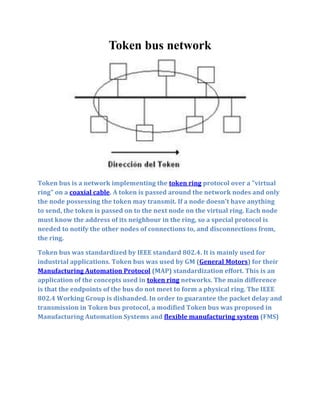
- 1. Token bus network Token bus is a network implementing the token ring protocol over a "virtual ring" on a coaxial cable. A token is passed around the network nodes and only the node possessing the token may transmit. If a node doesn't have anything to send, the token is passed on to the next node on the virtual ring. Each node must know the address of its neighbour in the ring, so a special protocol is needed to notify the other nodes of connections to, and disconnections from, the ring. Token bus was standardized by IEEE standard 802.4. It is mainly used for industrial applications. Token bus was used by GM (General Motors) for their Manufacturing Automation Protocol (MAP) standardization effort. This is an application of the concepts used in token ring networks. The main difference is that the endpoints of the bus do not meet to form a physical ring. The IEEE 802.4 Working Group is disbanded. In order to guarantee the packet delay and transmission in Token bus protocol, a modified Token bus was proposed in Manufacturing Automation Systems and flexible manufacturing system (FMS)
- 2. CSMA/CD
- 3. 1.Short for Carrier Sense Multiple Access / Collision Detection, a set of rules determining how networkdevices respond when two devices attempt to use a data channel simultaneously (called a collision). Standard Ethernet networks use CSMA/CD to physically monitor the traffic on the line at participating stations. If no transmission is taking place at the time, the particular station can transmit. If two stations attempt to transmit simultaneously, this causes a collision, which is detected by all participating stations. After a random time interval, the stations that collided attempt to transmit again. If another collision occurs, the time intervals from which the random waiting time is selected are increased step by step. This is known as exponential back off. CSMA/CD is a type of contention protocol. Networks using the CSMA/CD procedure are simple to implement but do not have deterministic transmission characteristics. The CSMA/CD method is internationally standardized in IEEE 802.3 and ISO 8802.3. 2.Carrier Sense Multiple Access (CSMA) is a probabilisticMedia Access Control (MAC) protocol in which a node verifies the absence of other traffic before transmitting on a shared transmission medium, such as an electrical bus, or a band of the electromagnetic spectrum. "Carrier Sense" describes the fact that a transmitter uses feedback from a receiver that detects a carrier wave before trying to send. That is, it tries to detect the presence of an encoded signal from another station before attempting to transmit. If a carrier is sensed, the station waits for the transmission in progress to finish before initiating its own transmission. "Multiple Access" describes the fact that multiple stations send and receive on the medium. Transmissions by one node are generally received by all other stations using the medium. Carrier sense multiple access with collision avoidance (CSMA/CA), incomputer networking, is a wireless network multiple access method in which: acarrier sensing scheme is used. anode wishing to transmit data has to first listen to the channel for a predetermined amount of time to determine whether or not another node is transmitting on the channel within the wireless range. If the channel is sensed "idle," then the node is permitted to begin the transmission process. If the channel is sensed as "busy," the node defers its transmission for a random period of time. Once the transmission process begins, it is still possible for the actual transmission of application data to not occur.[1][2]
- 4. CSMA/CA is a modification of carrier sense multiple access. Collision avoidance is used to improve CSMA performance by not allowing wireless transmission of a node if another node is transmitting, thus reducing the probability of collision due to the use of a random truncated binary exponential backoff time. Optionally, but almost always implemented, an IEEE 802.11 RTS/CTS exchange can be required to better handle situations such as the hidden node problem in wireless networking.[3] CSMA/CA is a layer 2 access method, not a protocol of the OSI model.
- 5. CSMA/CA (Carrier Sense Multiple Access/Collision Avoidance) is a protocol for carrier transmission in 802.11 networks. Unlike CSMA/CD (Carrier Sense Multiple Access/Collision Detect) which deals with transmissions after a collision has occurred, CSMA/CA acts to prevent collisions before they happen. In CSMA/CA, as soon as a node receives a packet that is to be sent, it checks to be sure the channel is clear (no other node is transmitting at the time). If the channel is clear, then the packet is sent. If the channel is not clear, the node waits for a randomly chosen period of time, and then checks again to see if the channel is clear. This period of time is called the backoff factor, and is counted down by a backoff counter. If the channel is clear when the backoff counter reaches zero, the node transmits the packet. If the channel is not clear when the backoff counter reaches zero, the backoff factor is set again, and the process is repeated.
- 6. Fiber Distributed Data Interface
- 7. definition - FDDI (Fiber Distributed Data Interface) is a set of ANSI and ISO standards for data transmission on fiber optic lines in a local area network (LAN) that can extend in range up to 200 km (124 miles). The FDDI protocol is based on the token ring protocol. In addition to being large geographically, an FDDI local area network can support thousands of users. FDDI is frequently used on the backbone for a wide area network (WAN). An FDDI network contains two token rings, one for possible backup in case the primary ring fails. The primary ring offers up to 100 Mbps capacity. If the secondary ring is not needed for backup, it can also carry data, extending capacity to 200 Mbps. The single ring can extend the maximum distance; a dual ring can extend 100 km (62 miles). FDDI is a product of American National Standards Committee X3-T9 and conforms to the Open Systems Interconnection (OSI) model of functional layering. It can be used to interconnect LANs using other protocols. FDDI-II is a version of FDDI that adds the capability to add circuit-switched service to the network so that voice signals can also be handled. Work is underway to connect FDDI networks to the developing Synchronous Optical Network (SONET). From Wikipedia, the free encyclopedia Jump to: navigation, search Dual-attach FDDI Board
- 8. Fiber Distributed Data Interface (FDDI) provides a 100 Mbit/s optical standard for data transmission in a local area network that can extend in range up to 200 kilometers (124 miles). Although FDDI logical topology is a ring-based token network, it does not use the IEEE 802.5 token ringprotocol as its basis; instead, its protocol is derived from the IEEE 802.4 token bustimed token protocol. In addition to covering large geographical areas, FDDI local area networks can support thousands of users. As a standard underlying medium it uses optical fiber, although it can use copper cable, in which case it may be refer to as CDDI (Copper Distributed Data Interface). FDDI offers both a Dual-Attached Station (DAS), counter-rotating token ring topology and a Single-Attached Station (SAS), token bus passing ring topology. FDDI was considered an attractive campus backbone technology in the early to mid 1990s since existing Ethernet networks only offered 10 Mbit/s transfer speeds and Token Ring networks only offered 4 Mbit/s or 16 Mbit/s speeds. Thus it was the preferred choice of that era for a high-speed backbone, but FDDI has since been effectively obsoleted by fast Ethernet which offered the same 100 Mbit/s speeds, but at a much lower cost and, since 1998, by Gigabit Ethernet due to its speed, and even lower cost, and ubiquity. FDDI, as a product of American National Standards Institute X3T9.5 (now X3T12), conforms to the Open Systems Interconnection (OSI) model of functional layering of LANs using other protocols. FDDI-II, a version of FDDI, adds the capability to add circuit-switched service to the network so that it can also handle voice and video signals. Work has started to connect FDDI networks to the developing Synchronous Optical Network SONET. A FDDI network contains two rings, one as a secondary backup in case the primary ring fails. The primary ring offers up to 100 Mbit/s capacity. When a network has no requirement for the secondary ring to do backup, it can also carry data, extending capacity to 200 Mbit/s. The single ring can extend the maximum distance; a dual ring can extend 100 km (62 miles). FDDI has a larger maximum-frame size (4,352 bytes) than standard 100 Mbit/s Ethernet which only supports a maximum-frame size of 1,500 bytes, allowing better throughput.
- 9. Designers normally construct FDDI rings in the form of a "dual ring of trees" (see network topology). A small number of devices (typically infrastructure devices such as routers and concentrators rather than host computers) connect to both rings - hence the term "dual-attached". Host computers then connect as single-attached devices to the routers or concentrators. The dual ring in its most degenerate form simply collapses into a single device. Typically, a computer-room contains the whole dual ring, although some implementations have deployed FDDI as a Metropolitan area network.
- 10. client–server 1.definition - Client/server describes the relationship between two computer programs in which one program, the client, makes a service request from another program, the server, which fulfills the request. Although the client/server idea can be used by programs within a single computer, it is a more important idea in a network. In a network, the client/server model provides a convenient way to interconnect programs that are distributed efficiently across different locations. Computer transactions using the client/server model are very common. For example, to check your bank account from your computer, a client program in your computer forwards your request to a server program at the bank. That program may in turn forward the request to its own client program that sends a request to a database server at another bank computer to retrieve your account balance. The balance is returned back to the bank data client, which in turn serves it back to the client in your personal computer, which displays the information for you. The client/server model has become one of the central ideas of network computing. Most business applications being written today use the client/server model. So does the Internet's main program, TCP/IP. In marketing, the term has been used to distinguish distributed computing by smaller dispersed computers from the "monolithic" centralized computing of mainframe computers. But this distinction has largely disappeared as mainframes and their applications have also turned to the client/server model and become part of network computing. In the usual client/server model, one server, sometimes called a daemon, is activated and awaits client requests. Typically, multiple client programs share the services of a common server program. Both client programs and server programs are often part of a larger program or application. Relative to the Internet, your Web browser is a client program that requests services (the sending of Web pages or files) from a Web server (which technically is called a Hypertext Transport Protocol or HTTP server) in another computer somewhere on the Internet. Similarly, your computer with TCP/IP installed allows you to make client requests for files from File Transfer Protocol (FTP) servers in other computers on the Internet. Other program relationship models included master/slave, with one program being in charge of all other programs, and peer-to-peer, with either of two programs able to initiate a transaction.
- 11. 2.Theclient–server characteristic describes the relationship of cooperating programs in an application. The server component provides a function or service to one or many clients, which initiate requests for such services. Functions such as email exchange, web access and database access, are built on the client–server model. Users accessing banking services from their computer use a web browser client to send a request to a web server at a bank. That program may in turn forward the request to its own database client program that sends a request to a database server at another bank computer to retrieve the account information. The balance is returned to the bank database client, which in turn serves it back to the web browser client displaying the results to the user. The client–server model has become one of the central ideas of network computing. Many business applications being written today use the client–server model. So do the Internet's main application protocols, such as HTTP, SMTP, Telnet, and DNS. The interaction between client and server is often described using sequence diagrams. Sequence diagrams are standardized in the Unified Modeling Language. Specific types of clients include web browsers, email clients, and online chat clients. Specific types of servers include web servers, ftp servers, application servers, database servers, name servers, mail servers, file servers, print servers, and terminal servers. Most web services are also types of servers. Comparison to peer-to-peer architecture This section requires expansion. In peer-to-peer architectures, each host or instance of the program can simultaneously act as both a client and a server, and each has equivalent responsibilities and status. Both client–server and peer-to-peer architectures are in wide usage today. Details may be found in Comparison of Centralized (Client-Server) and Decentralized (Peer-to-Peer) Networking. [edit]Advantages In most cases, a client–server architecture enables the roles and responsibilities of a computing system to be distributed among several independent computers that are known to each other only through a network. This creates an additional advantage to this architecture: greater ease of maintenance. For example, it is possible to replace, repair, upgrade, or even relocate a server while its clients remain both unaware and unaffected by that change. All data is stored on the servers, which generally have far greater security controls than most clients.[citation needed] Servers can better control access and resources, to guarantee that only those clients with the appropriate permissions may access and change data.
- 12. Since data storage is centralized, updates to that data are far easier to administer in comparison to a P2P paradigm. In the latter, data updates may need to be distributed and applied to each peer in the network, which is both time-consuming and error-prone,[citation needed] as there can be thousands or even millions of peers. Many mature client–server technologies are already available which were designed to ensure security, friendliness of the user interface, and ease of use.[citation needed] It functions with multiple different clients of different capabilities. [edit]Disadvantages As the number of simultaneous client requests to a given server increases, the server can become overloaded.[citation needed] Contrast that to a P2P network, where its aggregated bandwidth actually increases as nodes are added, since the P2P network's overall bandwidth can be roughly computed as the sum of the bandwidths of every node in that network. The client–server paradigm lacks the robustness of a good P2P network.[citation needed] Under client–server, should a critical server fail, clients’ requests cannot be fulfilled. In P2P networks, resources are usually distributed among many nodes. Even if one or more nodes depart and abandon a downloading file, for example, the remaining nodes should still have the data needed to complete the download
- 13. Architecture of P2P systems 1.definition - 1) Peer-to-peer is a communications model in which each party has the same capabilities and either party can initiate a communication session. Other models with which it might be contrasted include the client/server model and the master/slave model. In some cases, peer-to- peer communications is implemented by giving each communication node both server and client capabilities. In recent usage, peer-to-peer has come to describe applications in which users can use the Internet to exchange files with each other directly or through a mediating server. IBM's Advanced Peer-to-Peer Networking (APPN) is an example of a product that supports the peer-to-peer communication model. 2) On the Internet, peer-to-peer (referred to as P2P) is a type of transient Internet network that allows a group of computer users with the same networking program to connect with each other and directly access files from one another's hard drives. Napster and Gnutella are examples of this kind of peer-to-peer software. Major producers of content, including record companies, have shown their concern about what they consider illegal sharing of copyrighted content by suing some P2P users. Meanwhile, corporations are looking at the advantages of using P2P as a way for employees to share files without the expense involved in maintaining a centralized server and as a way for businesses to exchange information with each other directly. How Does Internet P2P Work? The user must first download and execute a peer-to-peer networking program. (Gnutellanet is currently one of the most popular of these decentralized P2P programs because it allows users to exchange all types of files.) After launching the program, the user enters the IP address of another computer belonging to the network. (Typically, the Web page where the user got the download will list several IP addresses as places to begin). Once the computer finds another network member on-line, it will connect to that user's connection (who has gotten their IP address from another user's connection and so on). Users can choose how many member connections to seek at one time and determine which files they wish to share or password protect. 2.Peer-to-peer systems often implement an abstract overlay network, built at Application Layer, on top of the native or physical network topology. Such overlays are used for indexing
- 14. and peer discovery and make the P2P system independent from the physical network topology. Content is typically exchanged directly over the underlying Internet Protocol (IP) network. Anonymous peer-to-peer systems are an exception, and implement extra routing layers to obscure the identity of the source or destination of queries. In structured peer-to-peer networks, peers (and, sometimes, resources) are organized following specific criteria and algorithms, which lead to overlays with specific topologies and properties. They typically use distributed hash table-based (DHT) indexing, such as in the Chord system (MIT).[2] Unstructured peer-to-peer networks do not provide any algorithm for organization or optimization of network connections.[citation needed]. In particular, three models of unstructured architecture are defined. In pure peer-to-peer systems the entire network consists solely of equipotent peers. There is only one routing layer, as there are no preferred nodes with any special infrastructure function. Hybrid peer-to-peer systems allow such infrastructure nodes to exist, often called supernodes.[3] In centralized peer-to-peer systems, a central server is used for indexing functions and to bootstrap the entire system.[citation needed]. Although this has similarities with a structured architecture, the connections between peers are not determined by any algorithm. The first prominent and popular peer-to-peer file sharing system, Napster, was an example of the centralized model. Gnutella and Freenet, on the other hand, are examples of the decentralized model. Kazaa is an example of the hybrid model. P2P networks are typically used for connecting nodes via largely ad hoc connections.[citation needed] Data, including digital formats such as audio files, and real time data such as telephony traffic, is passed using P2P technology. A pure P2P network does not have the notion of clients or servers but only equal peer nodes that simultaneously function as both "clients" and "servers" to the other nodes on the network. This model of network arrangement differs from the client–server model where communication is usually to and from a central server. A typical example of a file transfer that does not use the P2P model is the File Transfer Protocol (FTP) service in which the client and server programs are distinct: the clients initiate the transfer, and the servers satisfy these requests. The P2P overlay network consists of all the participating peers as network nodes. There are links between any two nodes that know each other: i.e. if a participating peer knows the location of another peer in the P2P network, then there is a directed edge from the former node to the latter in the overlay network. Based on how the nodes in the overlay network are linked to each other, we can classify the P2P networks as unstructured or structured. [edit]Structured systems Structured P2P networks employ a globally consistent protocol to ensure that any node can efficiently route a search to some peer that has the desired file, even if the file is extremely rare. Such a guarantee necessitates a more structured pattern of overlay links. By far the most common type of structured P2P network is the distributed hash table (DHT), in which a variant
- 15. of consistent hashing is used to assign ownership of each file to a particular peer, in a way analogous to a traditional hash table's assignment of each key to a particular array slot. [edit]Distributed hash tables Distributed hash tables Distributed hash tables (DHTs) are a class of decentralized distributed systems that provide a lookup service similar to a hash table: (key, value) pairs are stored in the DHT, and any participating node can efficiently retrieve the value associated with a given key. Responsibility for maintaining the mapping from keys to values is distributed among the nodes, in such a way that a change in the set of participants causes a minimal amount of disruption. This allows DHTs to scale to extremely large numbers of nodes and to handle continual node arrivals, departures, and failures. DHTs form an infrastructure that can be used to build peer-to-peer networks. Notable distributed networks that use DHTs include BitTorrent's distributed tracker, the Kad network, the Storm botnet, YaCy, and the Coral Content Distribution Network. Some prominent research projects include the Chord project, the PAST storage utility, the P- Grid, a self-organized and emerging overlay network and the CoopNet content distribution system (see below for external links related to these projects). DHT-based networks have been widely utilized for accomplishing efficient resource discovery[4][5] for grid computing systems, as it aids in resource management and scheduling of applications. Resource discovery activity involve searching for the appropriate resource types that match the user’s application requirements. Recent advances in the domain of decentralized resource discovery have been based on extending the existing DHTs with the capability of multi- dimensional data organization and query routing. Majority of the efforts have looked at embedding spatial database indices such as the Space Filling Curves (SFCs) including the Hilbert curves, Z-curves, k-d tree, MX-CIF Quad tree and R*-tree for managing, routing, and indexing of complex Grid resource query objects over DHT networks. Spatial indices are well suited for handling the complexity of Grid resource queries. Although some spatial indices can have issues as regards to routing load-balance in case of a skewed data set, all the spatial indices are more scalable in terms of the number of hops traversed and messages generated while searching and routing Grid resource queries.