Flowserve Valtek Mark One Control Valve
•
2 gostaram•5,346 visualizações

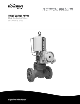
The Valtek Mark One globe control valve offers superior performance in liquid and gaseous services, while also permitting easy, fast and inexpensive maintenance.

Recomendados
Mais conteúdo relacionado
Mais procurados
Mais procurados (20)
Destaque
Destaque (17)
Semelhante a Flowserve Valtek Mark One Control Valve
Semelhante a Flowserve Valtek Mark One Control Valve (20)
Mais de Swanson Flo
Mais de Swanson Flo (17)
Último
Último (20)
Flowserve Valtek Mark One Control Valve
- 1. Experience In Motion TECHNICAL BULLETIN Valtek Control Valves Mark One Control Valves FCD VLENTB0001-03-AQ 10/15
- 2. Valtek Mark One Control Valves FCD VLENTB0001-03-AQ – 10/15 2 Body Assembly The Valtek® Mark One TM globe control valve offers superior performance in liquid and gaseous services, while also permitting easy, fast and inexpensive maintenance. The spring-cylinder actuated Mark One valve provides stiffness and maintains high positioning accuracy, repeatability, controlled high speed, and faithful response. The Mark One valve handles up to 150 psig (10.3 barg) supply air and has the thrust to shut off against much higher fluid pressures. The Mark One valve is designed so the spring, supply air pressure and fluid pressure itself combine to produce exceptionally tight shutoff. A self-aligning seat ring further enhances the shutoff capability of the Mark One valve. The Mark One valve is typically double top-stem guided and completely avoids contact between the plug and seat retainer. Many globe valve maintenance problems can be traced to cage- guiding. The close metal-to-metal contact between the cage and plug often result in galling and sticking. The clamped-in seat and top-entry trim permits easy, quick maintenance. Plus, with the Mark One valve’s high degree of parts interchangeability, fewer inventory parts are required. In addition, the actuator is lighter, smaller and easier to handle than comparable diaphragm actuators. The Valtek Mark One control valve is the industry choice for a simple, reliable, tough globe valve. S O Fail-safe spring Clamped-in Seat Ring: Valve may be disassembled quickly and easily by removing bonnet bolts. High Performance: Positioning accuracy to 0.1% full scale High Thrust Cylinder Actuator: Three standard sizes cover most applications. Each is easily reversible and features exceptional stiffness, repeatability and low hysteresis. Versatility: ANSI Class 600 (PN 100) body used for ANSI Class 150, 300 and 600 (PN 16, 40, 100) ratings through 4-inch (DN 100) Heavy Guiding: Two widely spaced guides on large- diameter stem. Plug does not guide in retainer.
- 3. 3 Valtek Mark One Control Valves FCD VLENTB0001-03-AQ – 10/15 flowserve.com Advantages and Features Advantages Features Design provides lower total lifetime cost High interchangeability between sizes and other Valtek control products Valve design minimizes requirements for stocking spare parts Rugged, heavy-duty parts provide extended life Actuator design allows simple, easy maintenance Versatile Globe, angle, three-way, and jacket styles offer multiple face-to-face standards Trim that does not stick or gall Double-stem guiding located out of flow stream Generous clearance between plughead and seat retainer Eliminates galling associated with cage-guiding Easy, fast and inexpensive Top-entry servicing Clamped-in seat ring Evenly compressed gasket – controlled gasket compression Separable flanges High degree of parts interchangeability Small, lightweight design Leakproof when closed Self-aligning seat ring Assisted shutoff from fluid pressure, cylinder spring, cylinder pressure High-thrust, spring-cylinder actuator Spring fails valve to desired position, pneumatics provide additional force Built for toughest service Corrosion-resistant construction High thrust overcomes high pressures Anti-cavitation and noise-trim options Heavy-duty plug stem Factory Mutual approved as a fuel service valve (0.75 - 3-inch/DN 20 - 80) Compact and easy to install Cylinder actuator smaller than most competitor’s actuators Lower center of gravity than comparable actuators Lighter weight means less pipe stress from static and dynamic loads Separable end flanges allow the valve to be installed in many orientations and compensate for flange misalignment Reliable, predictable service Stiff, high-thrust cylinder actuator Accurate positioning High repeatability Faithful response Controlled, high-speed stroking action
- 4. Valtek Mark One Control Valves FCD VLENTB0001-03-AQ – 10/15 4 Components Figure 2: Mark One Control Valve
- 5. 5 Valtek Mark One Control Valves FCD VLENTB0001-03-AQ – 10/15 flowserve.com Body Styles Figure 3: Globe-style body Globe-style bodies feature smooth, streamlined, constant-area internal passages with no pockets, permitting high capacity with minimum turbulence. They are designed with nearly constant wall thickness, providing lower weight and cost when manufactured in expensive stainless or alloy steels. Figure 5: Angle-style Body Except for the body and 1.5-inch (DN 40) seat ring, the angle-style Mark One valve is completely interchangeable with the globe style – all other valve parts remain the same. For additional body protection, a venturi seat ring, extending to the outlet flange, is available. Figure 4: Three-way Body Three-way bodies are used for either combining or diverting services. Due to Flowserve’s excellent parts interchangeability, a standard globe valve easily converts to three-way service with the addition of a three-way adaptor, upper seat ring, two gaskets, three-way plug and longer bonnet flange studs. Figure 6: Steam-jacketed Body The steam-jacketed Mark One valve uses a standard globe style body with oversized, blind flanges for a full jacket or standard flanges for a partial jacket. The jacket is rated for 150 psig (10.3 barg) and is equipped with a 0.75-inch NPT supply and drain connection.
- 6. Valtek Mark One Control Valves FCD VLENTB0001-03-AQ – 10/15 6 End Connections, Flanges and Bolting Mark One body facings come standard as raised face for either separable and integral flanges. To achieve better sealing with mating piping, the flange face is machined with spiral grooved serration. Other optional facings include smooth face, flat face, ring-joint, large and small tongue, and large and small groove. Separable End Flanges Interchangeable separable flanges are standard for valve bodies 0.5- through 4-inch (DN 15 -100) in ANSI Class 150, 300 and 600 (PN 16, 40, 100). With separable end flanges, an ANSI Class 600 (PN 100) body can be adapted for ANSI Class 150, 300 or 600 (PN 16, 40, 100) service by simply changing the end flanges. Separable flanges are usually furnished in carbon steel for maximum cost savings, although stainless steel can be specified if needed. Bonnet Flange The bonnet flange incorporates the same separable design as the end flanges and is normally manufactured in carbon steel; however, it can be specified in stainless steel when required. Bonnet Flange Bolting All sizes use studs and nuts that are furnished in 304 and 316 stainless steel, suitable for -423° to 1500° F (-253° to 816° C). These temperature limits are for maximum pressure permitted by ANSI B16.34, latest edition. Table 1: End Connections End Connection Valve Size Rating Class ANSI/ISA Face-to-Face Standard inches DN ANSI PN Separable Flange 0.5-4 15-100 150-600 16-100 S75.20 Integral Flange- Steel and Alloys 0.5-48 15-1200 150 16 S75.03 0.5-48 15-1200 300-600 40-100 0.5-24 15-600 900-2500 160-400 S75.16 Screwed (NPT) 0.5-2 15-50 150-600 16-100 S75.12 0.5-2 15-50 N/A 160-400 Socketweld 0.5-4 15-50 150-600 16-100 0.5-4 15-50 900-2500 160-400 Buttweld 0.5-4 15-100 150-600 16-100 S75.156-36 150-900 150-600 16-100 0.5-24 15-600 900-2500 160-400 Figure 7: Separable End and Bonnet Flanges Figure 8: End Flanges Bonnet Flange End Flange ANSI Class 150 (PN16) Bonnet Flange Bolting Body ANSI Class 600 (PN 100) ANSI Class 300 (PN 40) ANSI Class 600 (PN 100)
- 7. 7 Valtek Mark One Control Valves FCD VLENTB0001-03-AQ – 10/15 flowserve.com Gaskets and Clamps The Mark One valve is designed with the bonnet and seat ring gaskets fully retained. Since the bonnet bottoms metal-to-metal in the body, the bonnet gasket compression is determined by the depth of the gasket step on the bonnet, which is machined to provide the required gasket compression. When the bonnet is fully installed, force is transmitted through the seat retainer to secure the seat ring in position. The body, seat retainer and seat ring are all machined to close tolerances to provide the proper gasket compression. Unlike the bonnet, the seat ring does not always bottom in the body, allowing this small clearance to compensate for manufacturing tolerances and thermal expansion. Figure 9: Body Gaskets Table 2: Gasket Specifications Type Gasket Material Maximum Gasket Temp Minimum Gasket Temp 0 F 0 C 0 F 0 C Standard Gaskets Flat PTFE 350 177 -200 -130 Spiral Wound 316 S.S./Graphite 15002 8162 -320 -196 Alternate Gaskets Flat KEL-F 350 177 -3201 -1961 Flat FEP 400 204 -320 -196 Spiral Wound3 316 S.S./ Thermiculite® 1500 816 -20 -30 Metal O-Ring Inconel X-750 1500 816 -201 -301 1 Lower temperature available upon request. 2 Limited to 8000 F (4270 C) for oxidizing service. 3 Alloy spiral windings available upon request Yoke Clamps The actuator is typically attached to the Mark One body assembly with two precision-cast, stainless steel yoke clamps. In some cases, however, the actuator is bolted directly to the bonnet. Each clamp has an inclined plane surface which, when bolted together, securely fastens the actuator yoke to the bonnet. Unlike conventional threaded clamps, the clamp design permits easy removal even under extremely corrosive conditions. Associated bolts and locknuts are supplied in plated carbon steel, although stainless steel is also available when required. Figure 10: Yoke Clamp Bonnet Gasket Seat Ring Gasket Yoke Clamp
- 8. Valtek Mark One Control Valves FCD VLENTB0001-03-AQ – 10/15 8 Bonnet Types Figure 11: Mark One Bonnet Types Standard Bonnet The Mark One bonnet is usually constructed of the same material as the body and handles temperatures from -20° to 750° F (-30° to 400° C). See Table 4 on page 9 for packing limitations. Extended Bonnet The extended bonnet protects the packing from excessive heat or cold, which may inhibit valve performance. The bonnet is constructed of carbon steel for temperatures from -20° to 800° F (-30° to 427° C) and of 304 or 316 stainless steel for -150° to 1500° F (-100° to 816° C). Cold Box Extended Bonnet The cold box extended bonnet permits stagnated, moderate temperature gas to form in the bonnet, which protects the packing from the service fluid. Typically manufactured from 304 or 316 stainless steel, it handles temperatures down to -423° F (-253° C). Standard construction consists of stainless steel bonnet flange and bolting. Guardian II Formed Metal Bellows Seal Bonnet The Guardian II formed metal bellows seal can be used whenever service fluid leakage to atmosphere needs to be reduced to an absolute minimum. The standard metal bellows seal is rated for operation in processes ranging in temperature from -320° F to 1100° F (-196° to 593° C) and pressures to 1100 psig (75.9 barg). The flexible metal bellows is typically constructed of Inconel 625 and is also available in Hastelloy C-22. The Guardian II bellows seal allows for outside pressure to minimize bellows squirm, prolonging bellows life. Guardian Metal Bellows Seal Bonnet The Guardian metal bellows seal provides protection against unwanted packing leakage to atmosphere in processes involving caustic liquids or gases. The compact, lightweight design of the Guardian bellows assembly makes it ideal for services less than 650° F (343° C) and 310 psig (21.4 barg). The precision-formed bellows is avail- able in Inconel or Hastelloy C materials. NOTE: Bellows seals are designed for special service conditions and not to valve’s design class; therefore, complete and accurate service conditions must be specified. Standard Bonnet Cold Box Extended BonnetExtended Bonnet
- 9. 9 Valtek Mark One Control Valves FCD VLENTB0001-03-AQ – 10/15 flowserve.com Packing and Guiding Packing Box Standard Valtek packing boxes are deeper than most conventional types, providing the following advantages: 1. The spacing between the wiper set and the main upper packing set prevents contamination of the upper packing. The upper set is positioned far enough away from the wiper set to avoid contact with any part of the plug stem that has been exposed to the flowing medium. The wiper set is designed to minimize the amount of fluid on the plug stem. 2. Bonnets are designed to permit a wide variety of packing configurations, including a double set of packing, without changing bonnets. 3. Two widely spaced stem guides, when used with the Mark One’s large plug stem diameter, provide exceptional guiding. The upper stem guide also acts as a packing follower; the lower guide is situated close to the plug head for additional guiding support, ensuring accurate alignment of plug and seat ring. 4. Graphite-lined stainless steel guides provide superior guiding over wide temperature ranges and completely eliminate guide/stem galling. A variety of guides are available for various applications, including solid brass, Alloy 6 and glass-filled PTFE-lined stainless steel. Table 3: Guides Standard Materials Max. Temp. Min. Temp. Maximum Pressure Graphite- lined SS*** 15000 F 8160 C -3200 F -1960 C 1400 psig / 96.6 barg up to 2-in / DN 50 1000 psig / 69.0 barg 3-4 in / DN 80-100 850 psig / 58.6 barg 6 in DN 150 & up Glass filled 300° F 148.9° C -325° F -198.3° C 1400 psig / 96.5 barg @ 60°F / 15.5°C Solid Bronze 5000 F 2600 C -4230 F -2530 C Same as body Solid Alloy 6 15000 F 8160 C -4230 F -2530 C Same as body Table 4: Packing Bonnet Type Packing Material Service Fluid Temperature Limitation Standard** Bonnet PTFE, PTFE/AFP and Glass-filled PTFE 5000 F 5000 F 2600 C 2600 C Graphite/AFP 7500 F 4000 C Graphite/AFP, Inconel wire 7500 F* 4000 C* Graphite*** 7500 F* 4000 C* Extended** Bonnet PTFE, PTFE/AFP and Glass-filled PTFE 6000 F 3160 C Graphite/AFP 12000 F 6500 C Graphite/AFP, Inconel wire 12000 F 6500 C Graphite*** 15000 F 8160 C Cryogenic Extended Length** 15, 18-inch (38, 46 cm) PTFE -3200 F -1960 C 24, 27-inch (38, 46 cm) PTFE -4230 F -2530 C * Temperatures assume environmental temperature is less than 90° F (32° C); 8–12-inch (DN 200-300) ANSI Class 150-600 (PN 160-400) and 3–12-inch (DN 80-300) ANSI Class 900-2500 (PN 160-400) handles temperatures to 850° F (454° C). ** ANSI B16.34 specifies acceptable pressure temperature limits for pres- sure retaining materials. Consult the factory for additional information. *** Do not use graphite above 800° F (427° C) in oxidizing service such as air or oxygen. The use of graphite packing may require oversize actuators or heavier springs due to added friction. Lower Guide Wiper Packing Set Upper Packing Seat Upper Guide
- 10. Valtek Mark One Control Valves FCD VLENTB0001-03-AQ – 10/15 10 Flow Characteristics, Trim Types Equal Percentage Equal percentage is the characteristic most commonly used in process control. The change in flow per unit of valve stroke is directly proportional to the flow occurring just before the change is made. While the flow characteristic of the valve may be equal percentage, most control loops produce an installed characteristic, which approaches linear when the overall system pressure drop is large relative to that across the valve. Quick-open Quick-open plugs are used for on-off service and are primarily designed to produce maximum flow quickly. Linear Linear inherent characteristic produces equal changes in flow per unit of valve stroke regardless of plug position. Linear plugs are used on those systems where the valve pressure drop is a major portion of the total system pressure drop. Figure 13: Flow Characteristics Figure 14: Typical Trim Types Trim Types Three trim types are available. Standard full-area trim provides maximum CV. Reduced trim is available in a wide variety of sizes when lower CV values and large bodies are required. Integral trim uses a special seat machined into the body and an oversized plug to provide additional CV beyond the capabilities of full-area trim. Mark One valves can be converted from one trim type to another since all seat rings and plugs with a given size and pressure class are completely interchangeable. Integral trim is available by removing the seat ring and by changing the plug. TYPICAL INSTALLED CHARACTERIS TIC INHERENT CHARACTERISTIC 100 50 0 50 100 % Valve Stroke %Flow%Flow%Flow 100 50 0 50 100 100 50 0 50 100 TYPICALINS TALLED CHARACTERISTIC INHERENT CHARACTERISTIC INHERENT CHARACTERISTIC % Valve Stroke % Valve Stroke Equal Percentage Quick-open Linear Full Area IntegralReduced
- 11. 11 Valtek Mark One Control Valves FCD VLENTB0001-03-AQ – 10/15 flowserve.com Standard Trim, Pressure-balanced Trim Figure 15: Standard Trim Figure 16: Pressure-balanced Trim Mark One valve trim is designed to avoid the difficulties associated with screwed-in seats and cage-guiding. The seat ring is clamped into the body by the bonnet and seat retainer; thus, removal of the seat is easy even under extremely corrosive conditions. Unlike cage-guided trims that easily gall and stick, Mark One plugs are double-stem guided, avoiding contact between the seat retainer and plug. Because no contact is made with the plug, the retainer can be constructed of stainless steel rather than costly hard materials. The flow characteristic is determined by the plug contour, rather than by the opening in the retainer. Low-noise seat designs have been developed for better noise control in standard Mark One valves. Metal Seats Metal seated valves handle Class IV shutoff (ANSI B16.104, 1976 – FCI 70-2). This class calls for maximum permissible seat leakage of 0.01 percent of rated valve capacity. All Valtek control valves are seat-leak tested after assembly and are substantially lower in leakage than called for by this class. This exceptional seat tightness is obtained by aligning the seat ring with the plug during assembly. Additional seat tightness using metal seats is available as an option. In high pressure drop applications, pressure-balanced trim is used to reduce the thrust necessary to stroke the plug by reducing the trim off-balance area. Because the pressure- balanced plug fits closely to the retainer, this trim should only be used in generally clean services. Flow direction is under-the-plug for fail-closed and over- the- plug for fail-open. The seal area less the stem area is designed to be slightly larger than the seat area; therefore, the plug is off-balanced to close for flow under the seat and off-balanced to open for flow over the seat. Soft Seats The Mark One soft seat is used in applications requiring ANSI Class VI ‘bubble-tight’ shutoff. Its design consists of an elas- tomer sandwiched between two metal pieces. The assembled soft seat is interchangeable with the hard seat for a given size and pressure rating. Inserts are often constructed of PTFE; therefore, maximum temperature should be below 300° F (150° C) at 290 psig (20 barg). For temperatures below -85° F (-65° C), PTFE soft seats can be used in high-pressure applications. Figure 17: Typical Soft Seat Configuration Table 5: Standard Seal Temperature Ranges PTFE Sleeve -3200 F (-1960 C) @ full rating or 3000 F (1500 C) @ 150 psig (10.3 barg) Rene 41 8000 to 16000 F 4270 to 8710 C Spring-energized PTFE -3650 to 5750 F -2210 to 3020 C Viton -400 to 4370 F -400 to 2250 C Stem Guide Pressure- balanced Sleeve Sleeve Gasket Plug Plug Vent Plug Seals BonnetBonnet Plug Seat Ring Seat Retainer Insert Retainer Insert Soft Seat Ring
- 12. Valtek Mark One Control Valves FCD VLENTB0001-03-AQ – 10/15 12 Trim Materials, Data Standard plug and seat ring material is 316 stainless steel, except special alloy bodies where trims are funished in the same material as the body. A wide variety of services are successfully handled by stainless steel trim parts. Nevertheless, a general rule is for temperatures above 600º F / 316º C. Alloy 6 is stocked for many valve trim parts. This material offers a good combination of relative hardness and corrosion resistance. Special alloys, such as Alloy 20, Hastelloy C and Monel, are also available. Table 6: Material Harness Ratings Trim Material Hardness Rockwell C Corrosion Resistance* 316 S.S. 8 Excellent Alloy 6 44 Good to Excellent 416 S.S. 40 Fair 440C S.S. 56 Fair 17-4 PH 40 Excellent Colmonoy 45-50 Fair to Good Tungsten Carbide 72 Good on Bases Poor on Acids *General rule only. Check specific application Table 7: Standard Unbalanced Valve / Actuator Data Valve Size Rating Class Full Area Trim Size Seat Area Stem Diameter Stem Area Std. Act. Size* Stroke inch DN ANSI PN inch cm in2 cm2 in2 cm2 in2 cm2 inch cm 0.5 15 150-600 16-100 0.50 1.3 0.20 1.3 0.56 1.43 0.25 1.60 25 0.75 1.9 0.75 20 150-2500 16-400 0.72 1.8 0.41 2.6 0.56 1.43 0.25 1.60 25 0.75 1.9 1 25 150-600 900-1500 2500 16-100 160-250 400 0.81 0.81 0.72 2.1 2.1 1.8 0.52 0.52 0.41 3.3 3.3 2.6 0.56 0.56 0.56 1.43 1.43 1.43 0.25 0.25 0.25 1.60 1.60 1.6 25 25 25 0.75 0.75 0.75 1.9 1.9 1.9 1.5 40 150-600 900-1500 2500 16-100 160-250 400 1.25 1.25 1.00 3.2 3.2 2.5 1.20 1.20 0.79 7.9 7.9 5.1 0.88 0.88 0.88 2.22 2.22 2.22 0.60 0.60 0.60 3.88 3.88 3.88 25 50 50 1.00 1.00 0.75 2.5 2.5 1.9 2 50 150-600 900-1500 2500 16-100 160-250 400 1.62 1.62 1.25 4.1 4.1 3.2 2.07 2.07 1.23 13.4 13.4 7.9 0.88 0.88 0.88 2.22 2.22 2.22 0.60 0.60 0.60 3.88 3.88 3.88 25 50 50 1.50 1.50 1.00 3.8 3.8 2.5 3 80 150-600 900-1500 2500 16-100 160-250 400 2.62 2.62 2.00 6.7 6.7 5.1 5.41 5.41 3.14 34.9 34.9 20.3 1.13 1.50 1.13 2.86 3.81 2.86 0.99 1.77 0.99 6.39 11.40 6.39 50 100 100 2.00 2.00 1.50 5.1 5.1 3.8 4 100 150-600 900-1500 2500 16-100 160-250 400 3.50 3.50 2.62 8.9 8.9 6.7 9.62 9.62 5.41 62.1 62.1 34.9 1.13 1.50 1.50 2.86 3.81 3.81 0.99 1.77 1.77 6.39 11.40 11.40 50 100 100 2.50 2.50 2.00 6.4 6.4 5.1 6 150 150 300-1500 2500 16 40-250 400 5.00 5.00 4.00 12.7 12.7 10.2 19.63 19.63 12.57 126.7 126.7 81.1 1.13 2.00 2.00 2.86 5.08 5.08 0.99 3.14 3.14 6.39 20.30 20.30 50 100 100 3.00 3.00 3.00 7.6 7.6 7.6 8 200 150 300-600 900-1500 2500 16 40-100 160-250 400 6.25 6.25 6.25 5.00 15.9 15.9 15.9 12.7 30.68 30.68 30.68 19.63 197.9 197.9 197.9 126.7 1.50 2.00 2.50 2.50 3.81 5.08 6.35 6.35 1.77 3.14 4.91 4.91 11.40 20.30 31.70 31.70 100 100 100 100 4.00 4.00 4.00 3.00 10.2 10.2 10.2 7.6 10 250 150 300-600 900-1500 2500 16 40-100 160-250 400 8.75 8.75 8.00 6.25 22.2 22.2 20.3 15.9 60.13 60.13 50.27 30.68 388.0 388.0 324.3 197.9 2.00 2.50 3.00 3.00 5.08 6.35 7.62 7.62 3.14 4.91 7.07 7.07 20.30 31.70 45.60 45.60 100 100 100 100 4.00 4.00 4.00 4.00 10.2 10.2 10.2 10.2 12 300 150 300-600 900-2500 16 40-100 160-400 9.50 9.50 8.00 24.1 24.1 20.3 70.88 70.88 50.27 457.3 457.3 324.3 2.00 3.00 3.00 5.08 7.62 7.62 3.14 7.07 7.07 20.30 45.60 45.60 100 100 100 4.00 4.00 4.00 10.2 10.2 10.2 14 350 150 300-600 16 40-100 11.00 11.00 27.9 27.9 95.03 95.03 613.1 613.1 3.00 3.00 7.62 7.62 7.07 7.07 45.60 45.60 100 100 4.00 4.00 10.2 10.2 * Minimum standards actuator size. Oversized actuators may be required for large pressure drops.
- 13. 13 Valtek Mark One Control Valves FCD VLENTB0001-03-AQ – 10/15 flowserve.com Trim Data, Hard Facing Table 8: Standard Pressure-balanced Valve/Actuator Data Valve Size Rating Class Full Area Trim Size* Seat Area Stem Center Diameter Stem Area Sleeve Area Off-balance Area Std. Actuator Size StrokeFlow-under To Close Flow-over to Open in. DN ANSI PN in. cm in2 cm2 in cm in2 cm2 in2 cm2 in2 cm2 in2 cm2 in. mm. 2 50 600 1500 2500 100 250 400 1.62 1.62 1.25 4.1 4.1 3.2 2.07 2.07 1.23 14.4 14.4 7.9 0.562 0.562 0.562 3.63 3.63 3.63 0.25 0.25 0.25 3.63 3.63 3.63 2.58 2.41 1.55 16.6 15.5 10.0 0.26 0.09 0.07 1.7 0.6 0.5 0.51 0.34 0.32 3.3 2.2 2.1 25 50 50 1 1 1 3 3 3 3 80 600 1500 2500 100 250 400 2.62 2.62 2.00 6.7 6.7 5.0 5.41 5.41 3.14 34.9 34.9 20.3 0.875 0.875 0.875 5.65 5.65 5.65 0.60 0.60 0.60 3.88 3.88 3.88 6.77 6.49 3.86 43.7 41.9 24.9 0.76 0.48 0.12 4.9 3.1 0.8 1.36 1.08 0.72 8.8 7.0 4.6 50 100 100 1.5 2 1.5 4 5 4 4 100 600 1500 2500 100 250 400 3.50 3.50 2.62 9.0 9.0 6.7 9.62 9.62 5.41 62.0 62.0 34.9 0.875 1.125 1.125 5.65 7.26 7.26 0.60 0.99 0.99 3.88 6.41 6.41 11.41 11.41 6.77 73.6 73.6 43.7 1.19 0.80 0.37 7.7 5.2 2.4 1.79 1.79 1.36 11.5 11.5 8.8 50 100 100 2 2 2 5 5 5 6 150 150 600 1500 2500 16 100 250 400 5.00 5.00 5.00 4.00 13.0 13.0 13.0 10.0 19.63 19.63 19.63 12.57 126.7 126.7 126.7 81.1 1.125 1.5 1.5 1.5 7.26 9.70 9.70 9.70 0.99 1.77 1.77 1.77 6.41 11.40 11.40 11.40 22.69 23.76 22.69 15.03 146.4 153.3 146.4 97.0 2.06 2.36 1.29 0.69 13.3 15.2 8.3 4.4 3.06 4.13 3.06 2.46 19.7 26.6 19.7 15.9 50 100 100 100 2.5 2.5 2.5 2.5 6 6 6 6 8 200 600 1500 2500 100 250 400 6.25 6.25 5.00 15.9 15.9 13.0 30.68 30.68 19.63 197.9 197.9 126.7 1.5 2.0 2.0 9.70 13.00 13.00 1.77 3.14 3.14 11.40 20.30 20.30 35.78 35.78 23.76 230.9 230.9 153.3 3.33 1.96 0.99 21.5 12.6 6.4 5.10 5.10 4.13 32.9 32.9 26.6 100 100 100 3 4 3 19 26 19 10 250 600 1500 2500 100 250 400 8.00 8.00 6.25 20.0 20.0 15.9 50.27 50.27 30.68 324.3 324.3 197.9 2.0 2.5 2.5 13.00 16.00 16.00 3.14 4.91 4.91 20.30 31.70 31.70 58.36 58.36 37.12 376.5 376.5 239.5 4.95 3.18 1.53 31.9 20.5 9.9 8.09 8.09 6.44 52.2 52.2 41.6 100 100 100 3 4 4 19 26 26 12 300 600 1500 2500 100 250 400 9.50 9.50 8.00 24.0 24.0 20.0 70.88 70.88 50.27 457.3 457.3 324.3 2.5 2.5 2.5 16.00 16.00 16.00 4.91 4.91 4.91 31.70 31.70 31.70 82.52 79.53 56.75 532.4 513.1 366.2 6.73 3.74 1.57 43.4 24.1 10.1 11.64 8.65 6.48 75.1 55.8 41.8 100 100 100 4 4 4 26 26 26 14 350 150 600 1500 16 100 250 11.00 11.00 11.00 28 28.0 28.0 95.03 95.03 95.03 613.1 613.1 613.1 2.5 3.0 3.0 16.00 19.00 19.00 4.91 7.07 7.07 31.70 45.60 45.60 108.43 106.05 103.87 699.6 684.2 670.2 8.49 3.95 1.77 54.8 25.5 11.4 13.40 11.02 8.84 86.5 71.1 57.0 100 100 100 8 8 8 52 52 52 16 400 600 1500 100 250 12.75 12.75 32.4 32.4 127.68 127.68 823.8 823.8 3.0 3.0 19.00 19.00 7.07 7.07 45.60 45.60 148.49 140.61 958.1 907.2 13.74 5.86 88.7 37.8 20.81 12.93 134.3 83.4 100 100 8 8 52 52 * This data does not apply to ChannelStream or MegaStream trim. ** Minimum standard actuator size. Oversized actuators may be required for large pressure drops. Figure 18: Hard Facing Variations - Plug Figure 19: Hard Facing Variations - Seat CV Data Use Performance! valve sizing software for CV data according to trim characteristic, body rating, and flow direction. Seat Surface Full Contour Full ContourLower Guide Area Lower Guide Seat Surface Full Bore
- 14. Valtek Mark One Control Valves FCD VLENTB0001-03-AQ – 10/15 14 Standard Materials of Construction, Estimated Shipping Weights Table 9: Body Materials Sizes 0.5-48 inch (DN 15-1200); Class 150 - 600 (PN 16-100) 0.5-24 inch (DN 15-600); Class 900-2500 (PN 160-400) 0.5-12 inch (DN15-300) Class 4500 (PN 700) Forms Globe, angle, three-way ANSI Ratings Class 150, 300, 600, 900, 1500, 2500 (PN 16, 40, 100, 160, 250, 400) Materials Carbon steel, stainless steel, Monel, nickel, chrome-moly, Titanium, Alloy 20, bronze, Hastelloy B, Hastelloy C, other castable materials End Connections Separable flange: 0.5-4 inch (DN 15-100); Class 150-600 (PN 16-100) Integral flange; all sizes NPT: 0.5-2 inch (DN 15-50) Socketweld: 0.5-4 inch (DN 15-100) Grayloc: all sizes Separable End Flange Carbon steel, 316 stainless steel; other material as required Table 10: Bonnet Materials Types Standard, standard extension, special length extension, bellows seal, cryogenic Flange Separable Materials Bonnet: same as body Bellows: stainless steel, other materials as required Bellows Housing: carbon steel, 316 stainless steel, other materials as required Bonnet flange: carbon steel, 316 stainless steel, other materials as required Name plate Valves are equipped with stainless steel name plates. An example is illustrated below. Table 11: Estimated Shipping Weights Globe, Flanged Valves with Cylinder Actuators and Positioners Weight in Pounds (Kilograms) Add for Extd. Bonnet Size Cl 150 PN 16 Cl 300 PN 40 Cl 600 PN 100 Cl 900 PN 160 Cl 1500 PN 250 Cl 2500 PN 400inch DN 0.5-0.75 15-20 40 18 40 18 40 18 5 2 1 25 50 23 50 23 50 23 100 45 120 54 150 68 5 2 1.5 40 65 30 65 30 65 30 170 77 180 82 210 95 5 2 2 50 75 34 75 34 75 34 200 91 220 100 300 136 5 2 3 80 160 73 170 77 180 82 400 182 430 195 500 227 15 7 4 100 240 109 250 114 265 120 590 268 610 277 940 427 20 9 6 150 360 163 570 259 600 272 1000 454 1170 531 1400 636 40 18 8 200 590 268 790 359 830 377 1100 499 1320 599 1740 790 65 30 10 250 1050 477 1405 638 1600 726 2050 931 2200 999 2600 1180 90 41 Part Identification Nearly every part on a Valtek control valve has an identification number, along with material code number. For example, on the plug stem flats, the trim number and flow characteristic of the plug are identified. Table 12: Oversize Actuator Weights (lbs/kgs) Original Size Oversize Add 25 50 30/14 50 100 90/41 100 200 125/57 S/N ________________ MARK _____ SIZE _____ CLASS _________ T/N _________ Cv _________ CHAR _________ AIR TO ______________ SIGNAL _________________ BODY _______________ TRIM ___________________ TAG ____________________________________________________ P.O. ____________________________________________________ 55211 Flowserve Corporation
- 15. 15 Valtek Mark One Control Valves FCD VLENTB0001-03-AQ – 10/15 flowserve.com Standard Materials of Construction Table 13: Packing Configurations Standard, Twin seal, Vacuum seal Materials PTFE V-ring, PTFE/AFP*, AFP/Inconel wire, glass-filled PTFE V-ring, braided PTFE, graphite, other materials as required. Lubrication (optional) Lubricator with integral isolation valve Lubricator with additional isolation valve Table 14: Trim Characteristics Equal percentage, linear, quick-open Materials 316 stainless steel Alloy 20 304 stainless steel Nickel 347 stainless steel Titanium 416 stainless steel Monel Hastelloy B 17-4 PH Hastelloy 440C Hard Facings Materials: Alloy 6, No. 5 Colmonoy Types: seat surface, full contour, full bore, lower stem guide area. Soft Seat PTFE, FEP, KEL-F, polyurethane, PEEK Pressure- balanced Sizes: 2-inch (DN 50) and larger, Seal types: elastomer, metal Table 15: Guides Type Double-top stem Materials Glass-filled PTFE, graphite, Alloy 6, bronze, other materials as required Table 16: Gaskets Types Spiral wound: 304 or 316 stainless steel/non- asbestos filler, PTFE, graphite Flat: PTFE, soft metal Metal O-ring: Inconel X750/silver plated Table 17: Actuators Types Double-acting cylinder with positive fail-safe spring action Manual handwheel Electro-hydraulic Electro-mechanical Sizes Cylinder: 25, 50, 100 (standard); 200, 300, 400, 500, 600 (optional) Manual Handwheel: 9, 12, 18, 24 inch (23, 20, 46, 61 cm) diameter Auxiliary Side mounted: continuously connected Top mounted: continuously connected, push- only, limit stops Materials Cylinder: anodized aluminum Piston: anodized aluminum Actuator stem: 416 stainless steel Yoke: ductile iron O-rings: nitrile Action Air-to-open, air-to-close (field reversible) Max. Working Pressure 150 psig (10.3 barg) (Refer to IOM 2 for pres- sure limitations. Table 18: Positioner Types Digital, pneumatic, electro-pneumatic Input Signals Digital: 4-20 mA, HART/FF communication Pneumatic: 3-15, 3-9, 9-15, 6-30 psig (0-1, 0-0.6, 0.6-1, 0.4-2.1 barg) and split ranges Electro-pneumatic: 4-20, 10-50 mA Supply Pressure 40-150 psig (2.8-10.3 barg) (no supply regulator required) Standard Materials Aluminum, stainless steel, nitrile, nickel- plated brass Adjustments Stroke range, zero, balance pressure Action Air-to-open, air-to-close (field reversible) *Asbestos Free Packing (AFP)
- 16. Valtek Mark One Control Valves FCD VLENTB0001-03-AQ – 10/15 16 Dimensions Table 19: Globe Body Dimensions - ASME Class 150, 300 and 600 (inches/mm) Body Size A B H Clearance Above Actuator Required for Disassembly ISA 75.08.07 (S75.20) * ISA 75.08.01 (S75.03) ** Class 150-600; PN 16-100 Class 150; PN 16 Class 300; PN 40 Class 600; PN 100 Standard Bonnet Extended Bonnet NPS DN in. mm in. mm in. mm in. mm in. mm in. mm in. mm in. mm 0.5 15 8.51 2161 7.3 184 7.5 191 8.0 203 1.5 38 3.8 97 8.3 212 2.5 64 0.75 20 8.51 2161 7.3 184 7.6 194 8.1 206 1.5 38 3.8 97 8.3 212 2.5 64 1 25 8.5 216 7.3 184 7.8 197 8.3 210 1.8 44 3.8 97 8.3 212 2.5 64 1.5 40 9.5 241 8.8 222 9.3 235 9.9 251 2.3 59 5.2 132 9.7 246 4.0 102 2 50 11.5 292 10.0 254 10.5 267 11.3 286 2.3 57 5.4 138 9.9 252 4.5 114 3 80 14.0 356 11.8 298 12.5 318 13.3 337 3.4 86 6.8 172 12.3 312 5.8 147 4 100 17.0 432 13.9 353 14.5 368 15.5 394 5.2 133 8.4 214 13.9 354 7.5 190 6 150 17.8 451 5.5 139 10.1 256 15.6 395 10.0 254 6 150 18.6 473 20.0 508 5.8 146 12.3 311 17.8 451 10.0 254 8 200 21.4 543 7.1 180 12.5 318 18.0 457 10.9 277 8 200 22.4 568 24.0 610 7.5 190 14.4 365 19.9 505 11.4 290 10 250 26.5 673 8.4 214 14.1 359 19.6 498 11.9 302 10 250 27.9 708 29.6 752 8.9 227 14.1 359 20.6 524 12.1 308 12 300 29.0 737 9.6 243 14.1 359 19.6 498 12.6 320 12 300 30.5 775 32.3 819 16.3 413 22.8 578 12.6 320 * Separable Flange **Integral Flange 1 Valtek Standard Table 20: Globe Body Dimensions - ASME Class 900, 1500 and 2500 (inches/mm) Body Size A B H Clearance Above Actuator Required for Disassembly ISA 75.08.06 (S75.16 LONG) * Standard Bonnet Exteneded Bonnet Class 900 Class 1500 Class 2500 Class 900 & 1500 Class 2500 Class 900 & 1500 Class 2500 Class 900 & 1500 Class 2500 NPS DN in. mm in. mm in. mm in. mm in. mm in. mm in. mm in. mm in. mm in. mm in. mm 0.5-1 15-25 11.5 292 11.5 292 12.5 318 1.8 46 1.8 46 5.6 124 6.8 173 10.1 257 11.3 287 3.6 91 3.6 91 1.5 40 13.1 333 13.1 333 15.0 381 2.7 69 2.4 61 8.7 221 8.7 221 13.2 335 13.2 335 5.6 142 5.6 142 2 50 14.8 375 14.8 375 16.3 413 2.8 71 3 76 8.7 221 8.7 221 13.2 335 13.2 335 6.1 155 6.1 155 3 80 17.4 441 18.1 460 26.0 660 4.2 107 3.7 94 11.4 290 12.9 328 18.4 467 19.9 506 8.4 213 8.3 211 4 100 20.1 511 20.9 530 29.0 737 4.4 112 5.4 137 12.4 315 14.6 371 19.4 493 21.6 549 9.7 246 10.7 272 6 150 28.1 714 30.3 768 34.0 864 7.2 183 7.3 185 19.4 493 17.4 442 26.4 671 27.3 693 12.2 310 13.6 345 8 200 36.0 914 38.3 972 40.3 1022 9.4 239 10.3 262 18.6 472 24.3 617 24.2 615 31.3 795 16.7 424 17.8 452 10 250 39.0 991 42.0 1067 54.01 13721 11.2 285 10 254 21.9 556 26 660 28.9 734 33 838 18.3 465 19.5 495 12 300 44.5 1130 48.0 1219 62.01 15751 14 356 12.9 328 26.6 676 28 711 33.6 853 35 889 19.4 493 20.5 521 14 350 49.5 1257 49.5 1257 630 31.8 808 20.5 521 * Integral Flange 1 Valtek Standard H A B MATCH LINE H MATCH LINE A
- 17. 17 Valtek Mark One Control Valves FCD VLENTB0001-03-AQ – 10/15 flowserve.com Dimensions Table 21: Globe Cold Box Extended Bonnet (inches/mm)* Body Size Body Rating H inch DN ANSI Class PN Standard Cold Box Extension 0.5-1 15-20 150-600 16-100 15.0 381 24.0 610 27.0 686 1.5 40 150-600 16-100 15.0 381 24.0 610 27.0 686 2 50 150-600 16-100 15.3 387 24.3 616 27.3 692 3 80 150-600 16-100 18.0 457 24.0 610 27.0 686 4 100 150-600 16-100 18.0 457 24.0 610 27.0 686 6 150 150 16 18.0 457 24.0 610 27.0 686 Table 22: Angle Body (inches/mm) Body Size Body Rating A H Clearance Required for Disassembly inch DN ANSI Class PN Standard Bonnet Extended Bonnet 0.5-1 15-25 150-600 16-100 4.3 108 3.1 78 7.6 192 2.5 64 1.5 40 150-600 16-100 4.8 121 3.6 92 8.1 206 4.0 102 2 50 150-600 16-100 5.8 146 3.9 100 8.2 214 4.5 114 3 80 150-600 16-100 7.0 178 4.9 124 10.4 264 5.8 147 4 100 150-600 16-100 8.8 222 6.2 156 11.7 295 7.5 190 6 150 150 16 8.9 226 7.1 180 12.6 320 10.0 254 300-600 40-100 11.0 279 9.5 241 15.0 381 10.0 254 8 200 150 16 13.0 330 9.0 229 14.5 368 13.8 349 300-600 40-100 13.0 330 10.8 275 16.3 414 13.8 349 0.5-1 15-25 900-1500 160-250 5.5 140 4.7 119 9.2 234 3.6 90 2500 400 6.0 152 5.8 147 10.3 262 3.6 90 1.5 40 900-1500 160-250 6.5 165 6.5 165 11.0 279 5.6 142 2500 400 7.5 191 7.0 178 11.5 292 5.6 142 2 50 900-1500 160-250 7.3 185 7.1 180 11.6 295 6.1 155 2500 400 8.9 226 7.9 201 12.4 315 6.1 155 3 80 900-1500 160-250 9.3 236 9.8 249 16.8 427 8.4 213 2500 400 13.0 330 11.2 284 18.2 462 8.3 211 4 100 900-1500 160-250 12.5 318 11.1 282 18.1 460 9.7 246 2500 400 14.5 368 12.6 320 19.6 498 10.7 272 6 150 900-1500 160-250 13.9 353 13.3 338 20.3 516 12.2 310 2500 400 17.0 432 16.1 409 23.1 537 13.6 345 8 200 900-1500 160-250 16.4 417 14.5 368 21.5 547 16.7 424 2500 400 20.1 511 20.8 528 27.8 706 17.8 452 10 250 900-1500 160-250 19.5 495 15.6 396 22.6 574 18.3 465 2500 400 25.0 635 21.1 536 28.1 714 16.3 414 *For all other body styles consult factory H MATCH LINE H A MATCH LINE A
- 18. Valtek Mark One Control Valves FCD VLENTB0001-03-AQ – 10/15 18 Dimensions Table 23: Three-way Body (inches/mm) Body Size A B C D H Clearance Required for Disassembly Sep. Flange Class* 150-600 PN 16-150 Integral Flange* Standard Bonnet Extended Bonnetin DN Class 150 PN 16 Class 300 PN 40 Class 600 PN 100 0.5-0.75 15-20 8.5 216 7.3 184 7.6 194 8.1 206 1.5 38 3.4 87 4.3 108 6.7 170 11.2 284 3.4 86 1 25 8.5 216 7.3 184 7.8 197 8.3 210 1.8 44 3.4 87 4.3 108 6.7 170 11.2 284 3.4 86 1.5 40 9.5 241 8.8 222 9.3 235 9.9 251 2.3 59 5.4 137 4.8 121 9.1 230 13.4 341 5.0 127 2 50 11.5 292 10.0 254 10.5 267 11.3 286 2.3 59 5.6 143 5.8 146 9.3 236 13.7 347 5.5 140 3 80 14.0 356 11.8 298 12.5 318 13.3 337 3.4 86 7.6 194 7.0 178 13.0 329 18.5 470 7.1 181 4 100 17.0 432 13.9 353 14.5 368 15.5 394 5.2 133 9.9 251 8.5 216 16.7 423 22.1 562 9.4 240 6 150 17.8 451 5.5 139 14.0 356 8.9 226 21.6 548 26.6 675 11.6 294 6 150 18.6 473 20.0 508 5.8 146 16.0 406 10.0 254 25.8 654 31.3 794 11.6 294 8 200 21.4 543 7.0 179 15.0 381 10.7 272 23.9 608 29.4 748 12.2 310 8 200 22.4 568 24.0 610 7.5 191 18.3 464 12.0 305 30.2 767 35.7 907 12.2 310 * ANSI/ISA B16.10, latest edition ** Per ANSI/ISA S75.03, latest edition C D B MATCH LINE H A
- 19. 19 Valtek Mark One Control Valves FCD VLENTB0001-03-AQ – 10/15 flowserve.com Applications (Right) A liquid nitrogen loading facility in Australia uses two Mark One valves for its emergency fire water system. (Left) Mark One valves used to operate a PSA skid. This 8-inch back-pressure control valve operates in a liquid hydrocarbon plant with a 580 psi/40 bar upstream pressure This cryogenic Mark One is used for aerospace testing as an O2 vent. A 4-inch Mark One with side-mounted handwheel operates a boiler feedwater system at a pulp plant. This 2-inch Guardian II operates in a chemical plant.
- 20. flowserve.com To find your local Flowserve representative: For more information about Flowserve Corporation, visit www.flowserve.com or call USA 1 800 225 6989 Flowserve Corporation has established industry leadership in the design and manufacture of its products. When properly selected, this Flowserve product is designed to perform its intended function safely during its useful life. However, the purchaser or user of Flowserve products should be aware that Flowserve products might be used in numerous applications under a wide variety of industrial service conditions. Although Flowserve can (and often does) provide general guidelines, it cannot provide specific data and warnings for all possible applications. The purchaser/user must therefore assume the ultimate responsibility for the proper sizing and selection, installation, operation, and maintenance of Flowserve products. The purchaser/user should read and understand the Installation Operation Maintenance (IOM) instructions included with the product, and train its employees and contractors in the safe use of Flowserve products in connection with the specific application. While the information and specifications contained in this literature are believed to be accurate, they are supplied for informative purposes only and should not be considered certified or as a guarantee of satisfactory results by reliance thereon. Nothing contained herein is to be construed as a warranty or guarantee, express or implied, regarding any matter with respect to this product. Because Flowserve is continually improving and upgrading its product design, the specifications, dimensions and information contained herein are subject to change without notice. Should any question arise concerning these provisions, the purchaser/user should contact Flowserve Corporation at any one of its worldwide operations or offices. © 2015 Flowserve Corporation, Irving, Texas, USA. Flowserve is a registered trademark of Flowserve Corporation. FCD VLENTB0001-03-AQ Printed in USA. October 2015 USA Flowserve Flow Control Division 1350 N. Mt. Springs Parkway Springville, UT 84663 USA Phone: +1 801 489 8611 Fax: +1 801 489 3719 Austria Flowserve Control Valves GmbH Kasernengasse 6 9500 Villach Austria Phone: 43 (0) 4242 41 181 0 Fax: 43 (0) 4242 41181 50 France Flowserve France S.A.S. BP 60 63307 Thiers Cedex France Phone: 33 4738 04266 Fax: 33 4738 01424 India Flowserve India Controls Pvt Ltd. Plot # 4, 1A, Road #8 EPIP Whitefield Bangalore, Karnataka, 560066 India Phone: 91 80 40146200 Fax: 91 80 28410286 China Flowserve Fluid Motion and Control (Suzhou) Co., Ltd. No. 35, Baiyu Road Suzhou Industrial Park, Suzhou Jiangsu Province, P.R. 215021 China Phone: 86 512 6288 8790 Fax: 86 512 6288 8736 Singapore Flowserve Pte. Ltd. 12 Tuas Avenue 20 Republic of Singapore 638824 Phone: 65 6879 8900 Fax: 65 6862 4940 Saudi Arabia Flowserve Abahsain Flow Control Co., Ltd. Makkah Road, Phase 4 Plot 10 & 12, 2nd Industrial City Damman, Kingdom of Saudi Arabia Phone: +966 3 857 3150 ext. 243 Fax: +966 3 857 4243